Pioneer KEH P4500R djvu
PIONEER
The Art of Entertainment
KEH-P4500R/X1M/EW

MULTI-CD CONTROL HIGH POWER CASSETTE PLAYER WITH RDS TUNER


NOTĘ:
# See the separate manuał CX-631(CRT1640) for the cassette mechanism description.
# The cassette mechanism assy employed in this model is one of X-2L series
# This service manuał does not describe the CD test modę.
For the operations in the CD test modę, refer to the CD player's Service Manuał.
1. SAFETY INFORMATION............................................2
2. EXPLODED VIEWS AND PARTS LIST.......................3
3. SCHEMATIC DIAGRAM...........................................12
4. PCB CONNECTION DIAGRAM................................30
5. ELECTRICAL PARTS LIST........................................42
6. ADJUSTMENT..........................................................52
7. GENERAL INFORMATION.......................................56
7.1 PARTS.................................................................56
7.1.1 IC................................................................56
7.1.2 DISPLAY....................................................61
7.2 DISASSEMBLY...................................................64
7.3 BŁOCK DIAGRAM..............................................66
PIONEER ELECTRONIC CORPORATION 4-1, Meg uro 1-Chome, Meguro-ku, Tokyo 153, Japan PIONEER ELECTRONICS SERVICE INC. P.O.Box 1760, Long Beach, CA 90801-1760 U.S.A.
PIONEER ELECTRONIC [EUROPE] N.V. Haven 1087 Keetberglaan 1, 9120 Melsele, Belgium
PIONEER ELECTRONICS ASIACENTRE PTE.LTD. 501 Orchard Road, #10-00, Lane Crawford Place, Singapore 0923
K-FEU SEPT. 1997 Printed in Belgium
© PIONEER ELECTRONIC CORPORATION 1997
3. SCHEMATIC DIAGRAM
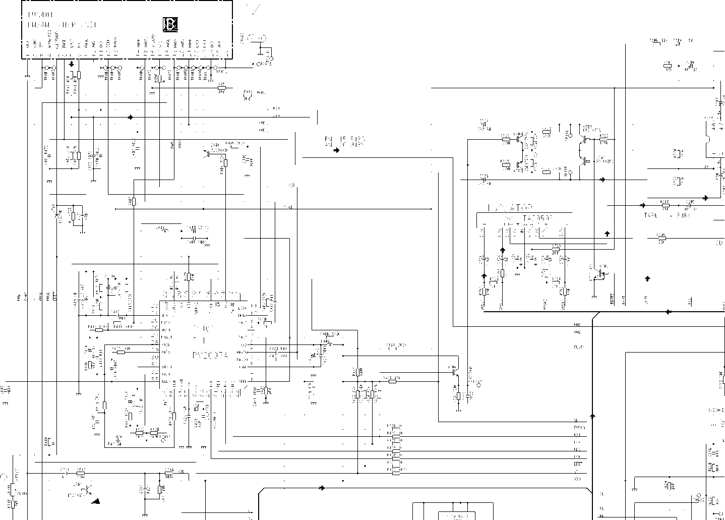
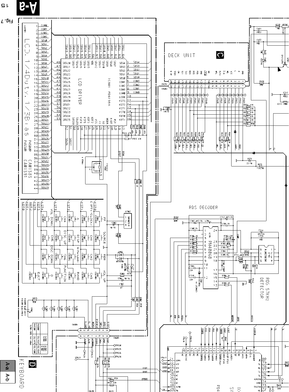
3.1 OVERALL CONNECTION DIAGRAM(GUIDE PAGE) (KEH-P4500R/X1M/EW, P4530R/X1M/EW)
Notę: When ordering service parts, be surę to refer to “EXPLODED VIEWS AND PARTS LIST” or “ELECTRICAL PARTS
LIST”.
|
Large size | |||
|
SCH diagram | |||


1 2

m TUNER AMR UNIT

Fig. 6

A-a A-b
□ISl7cd(łdaE:Sl7cd(łdaaSl7cd-H3>l
□ISl7cd(łdaE:Sl7cd(łdaaSl7cd-H3>l
1 e

A-a A-b

□ISl7cd(łdaE:Sl7cd(łdaaSl7cd-H3>l

\RD UNIT
|
-n- |
Symbol indi |
cat es a |
res i |
'Stor. | |||||
|
No di ffer er |
it i at i on |
i s n |
-ad e b et\ |
ve e n |
ch i |
presistors and |
De |
;cimał points for resistor | |
|
d i s cr et e r e |
■s i st or s . |
ar |
id capacitor f ixed values | ||||||
|
1 T |
Symb o 1 in di |
cat es a |
c apacit or. |
ar |
• e expressed as | ||||
|
No di ff er er |
it i at i on |
i s n |
*ad e b et \ |
veen |
ch i |
p cap acit or s and |
2 |
. 2—>2 R 2 | |
|
discrete capaci tors |
0 |
.022^R022 | |||||||
|
Th e |
A mar k f oun d |
on some |
com |
pon en t p |
ar t s |
i n |
di cates | ||
|
t h e |
importance |
of t h e s. |
af e t |
y f act or |
• o f |
t h e |
part. | ||
|
Th er |
' ef or e, when |
r ep 1aci i |
ag. |
be surę |
to l |
j se |
parts o f | ||
|
i der |
11ica 1 des i g |
nat i on. | |||||||
cp
A-a A-b
□ISl7cd(łdaE:Sl7cd(łdaaSl7cd-H3>l
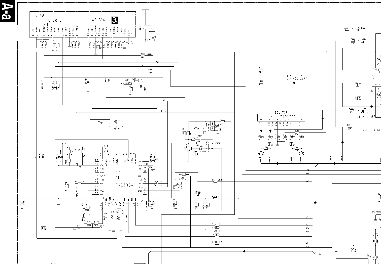
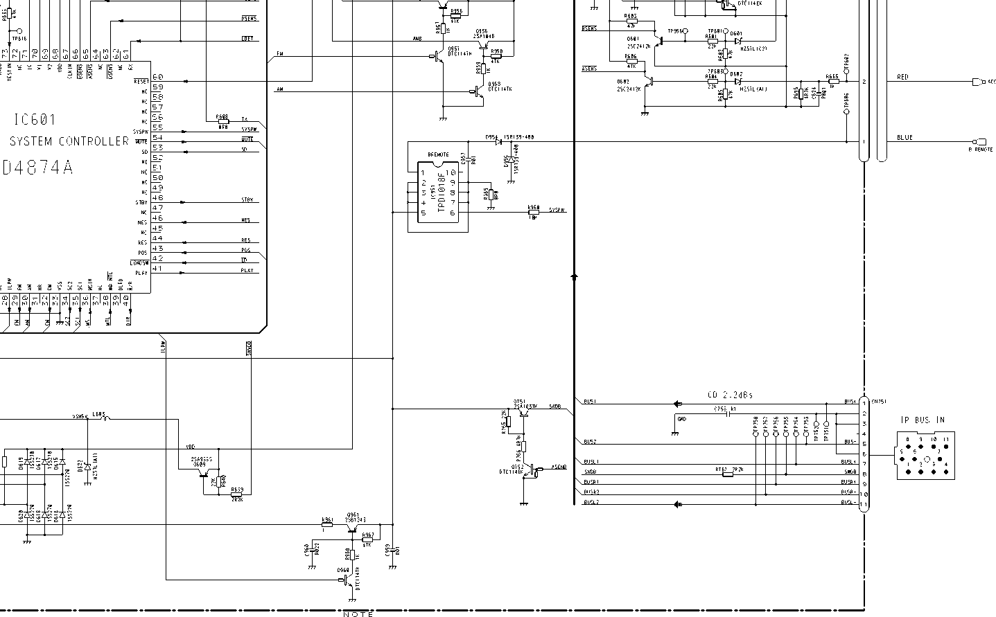
3.2 OVERALL CONNECTION DIAGRAM(GUIDE PAGE) (KEH-4510R/X1M/EE)
|
\ | |||
|
Large size | |||
|
SCH diagram | |||


Fig. 9
□
A d
A-b
FM —12 d 8 S AM -22d8S
□ISl7cd(łdaE:Sl7cd(łdaaSl7cd-H3>l


A-a
A-b
o
□ISl7cd(łdaE:Sl7cd(łdaaSl7cd-H3>l
ss

A-a A-b
i H TUNER AMR UNIT

□ISl7cd(łdaE:Sl7cd(łdaaSl7cd-H3>l

es
h i- Syrnb ol i nd i C3t es a resistor.
No di fferenti ati on is madę between chip resi stors and discrete resistors.
ID UNIT
|
Hl- |
Symb o 1 in d i |
cat es |
a capacitor. | ||
|
No differer |
11 i a t i o |
n is madę between |
ch i |
p cap acit or s | |
|
discrete ce |
>pac i to |
r s . | |||
|
Th e |
Ama~k found |
on soi |
ne component parts |
i n |
dicat es |
|
t h e |
importance |
of t h e |
s af e ty f ac t or of |
the |
part. |
|
Th er |
■ ef o- e, wh en |
r ep 1 3' |
oing, be surę to i |
ise |
parts o f |
|
i der |
11ica 1 des i g |
nat i on |
Decimal points for resistor and capacitor fixed values are expressed as 2.2^2R2 0.022^R022
A-a A-b
□ISl7cd(łdaE:Sl7cd(łdaaSl7cd-H3>l
3.3 FM/AM TUNER UNIT(KEH-P4500R/X1M/EW, P4530R/X1M/EW)
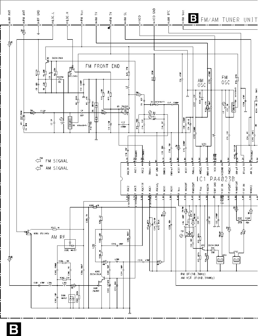

UNIT
Q
C5
O.
2
O
O

Fig. 12
3.4 TUNER UNIT(KEH-P4510/X1M/EE)

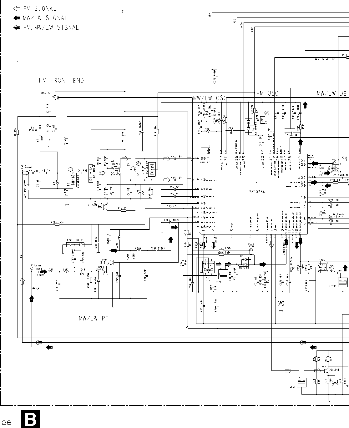
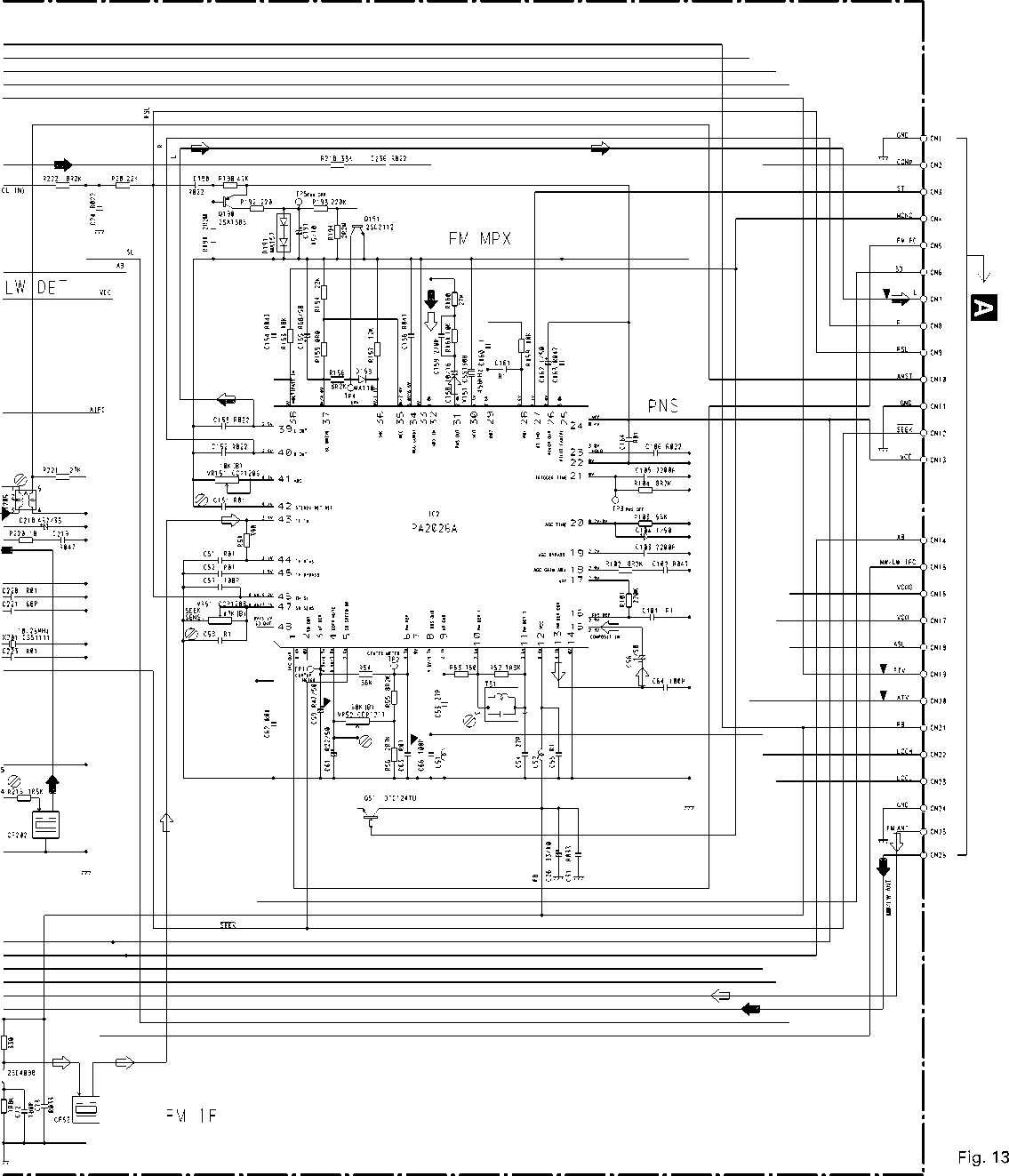

—8 . 24dB5 (300nnV) ±1 dB

Ul CN ^ |>- CQ
UJ O O O I0-1
Z Ul Ul |l— ^
|cn co
LOAD GND [Pwr) POS RES
Fig. 14
23
4. PCB CONNECTION DIAGRAM
NOTĘ FOR PCB DIAGRAMS
1. The parts mounted on this PCB include all necessary parts for several destination.
For further information for respective destinations, be surę to check with the schematic diagram.
2. Viewpoint of PCB diagrams
IC, Q
ADJ
Connector Capacitor

0951
0952 IC751
0953
Q604
IC301
0407
0956
0955
0606
0961
Q203 0205
0204
0708 0609 IC604 0707 0302
CORD ASSY
VR701

|il CN901
,,, N
f *
(f3p<D
Qi
-+ 9-
•*S
666666B666
99999^9,988
•*§
•*K «Wtg
©
i
|
:£r |
J............1 |
|
O |
o |
|
O |
1 |
|
©* | |
|
O | |
|
;!=3 |
El □
n
M
tn
tf)
O
m
>
Sl7cd(łdaE:Sl7cd(łdaaSl7cd-H3>l
Wyszukiwarka
Podobne podstrony:
keh p5015 djvu ServiceManuał KEH-P5015/X1M/ES ORDER NO.CRT2583 MULTI-CD CONTROL HIGH POWER CASSETTE
DEH 2000R djvu ServiceManuał DEH-2000R/X1N/EW ORDER NO. CRT2312 HIGH POWER CD PLAYER WITH RDS TUNER
DEH 2130R djvu SerniceManuał DEH-2130R/X1M/EW ORDER NO. CRT2434 HIGH POWER CD PLAYER WITH RDS
deh p2550 djvu sound. vision. sou! Service Manuał DEH-P2550/XM/ES ORDER NO. CRT2983 MULTI-CD CONTROL
S20C 409120813070 & The Art of Exquisite Felted KnitsGiną Wilde Forcword by Yoshiko Twa m o to W
125x125 zen logo zeńcart the art of e-commeree get the Magie of Zen Cart ...ifyou have to think yoj
image001 The Słotę of the Art of Science Fiction NowEdited by Roger Elwood and Robert Siłverberg A c
Art Newspaper, The Art of Record Production journal Art on Paper Art on the linę Art on View : the N
S20C 409120813070 & The Art of Exquisite Felted KnitsGiną Wilde Forcword by Yoshiko Twa m o to W
logo żencart the art of e-commerce
50 (335) The art of decorating items with rolled-up strips of coloured paper goes back to the fiftee
więcej podobnych podstron