Dibujo2
44
1


Building Modelcard Planes
Card modeling in Eastern Europę remained popular long after it went out of style in the West and design development continued. In the last few years a number of private companies have appeared, the poiiticaJ limitations on subjects have been lifted and the quality of the paper and printing have improved to the point that a good supply of top-notch models are now reliably available.
Building paper models is not difficult - it is just different from other forms of modeling and has its own methods. These are advanced models and a knowledge of the basie construction techniques is assumed by the publisher. Therefore we offer some hints to supplement the diagrams and abbreviated directions offered.
The tool necdcd are the usual for all paper modeling: a pair of scissors and a hobby knife with a number 11 blade for cutting out the parts,adull knife for scoring thefold lines,aruler forstraightscoring and cutting, perhaps a pair of tweezers for handling smali parts and a thickened whitecraftglue, 'Tacky" typebest, forgluing the model together. Water based felt pens are good for touching up the edges of the paper to match the color of the parts.
Additional materiał needed, not furnished in thesc books, is: thin but stiff notepad-backing-type cardboard, about 1 mm. thick for backing the intenor fonner parts, thin acetate, 3 mil to 5 mil, for the canopies, 18 gauge floral wire for landing gear and other parts, a few round toothpicks and some grey thread for antenna.
The fold lines are not generally marked as such but are usualiy obvious. Score them with a duli knife for good, sharp bends.
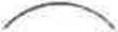
The fuselage construction for these models is one of three types. Which type can be seen from the interior fuselage diagram.

C 2 formers and no strip per cylinder

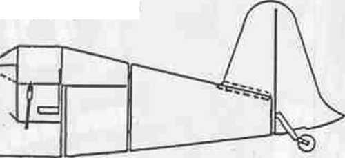
All start by rounding the part over the edge of a table. Then:
For A. Connect the part into a cylinder by gluing the long tab under the other long edge. Glue one-half of the connecting strip, up to its middle linę, inside one end of the cylinder. Then glue the former one-half way into the strip, that is, at the end of the cylinder. When the cylinders are to be connected, the open end of one cylinder is pushed over the pro-truding half of its neighboi^s strip, the align-mentchecked and glued there.
For B. Make the cylinder and install the former flush in one end. Connect the cylinders by matching up and butt gluing the open end of one cylinder directly to the former end of its neighbor.
ForC. Make cylinder 1 and install formers flush in both ends.
Then the nearest former from the ajoining cylinder is glued on the end of the first cylinder while the furthest former goes fludh in the far end of the ajoining cylinder. The open end of thisncxt cylinder fits over the flange madę by the former glued onto the first cylinder. Continue this as long as the diagram shows the double formers.
Some planes employ a mixture of the above.
Most wings employ method C , but herc the outer pancls are madę separatcly and then glued to the inner panels at the formers.
The formers, spars, ribs, wheel dises, parts printed on thin paper and other parts as stipulated in the directions are glued, best with a glue stick, to solid thin cardboard, not morę than 1 mm.thick. Then they are cut out precisely.
Proceed in numerical order.
The canopies are madę by cutting out the glass are as, leaving only the frame.s with some area around them. Glue the frames on a piece of acetate carefuliy with very thin lines oftacky glue and when dry cut out the outline of the frame precisely. Then form and glue together and in its place.
The wheels are mado by gluing the wheel dises on top of each other with the black dises on the outsides. Sometimes there is only one disc with the number of dupiicates to be madę. When the glued wheel is dry, carve and then sand the tread round and then blacken it with a felt pen. Drill a hole thru the center for the wire axcl.
The wire parts are generally, but not always, wholly or partially covered with paper parts. In some cases round toothpicks can be substituted for wire parts. The wire diagrams are fuli scalę so the wire can be bent right on the diagrams.
Following these hints along with the diagrams and directions given in the books, and, working with care and paticnce, the results will be truły amazing.


SHLTS • PLANES » CAES • CASTLES ind MORĘ Papłk Modkls Lvtł*natxonai.
S910 S.W. Uonnle Br*e Drłve, He»vcrton. Oregoo 97008
I» li I

H
Wyszukiwarka
Podobne podstrony:
F3F 1pmi instr A4 Building Modelcard Planes Card modeling in Eastern Europę remained popular long af
Mąkinia, J., Wells, S.A., Zima, P. (2005). Temperaturę modeling in activated sludge Systems: a case
Zał. nr 4 do ZW 64/2012 FACULTY OF ELECTRONICS SUBJECT CARD Name in Polish Miernictwo 2 Name in
Zał. nr 4 do ZW 64/2012 FACULTY OF ELECTRONICS SUBJECT CARD Name in Polish Grafika
Zał. nr 3 do ZW FACULTY OF ELECTRONICS SUBJECT CARD Name in Polish: Podstawy
Zał. nr 4 do ZW 64/2012 FACULTY ELECTRONICS SUBJECT CARD Name in Polish Podstawy automatyki i
Zał. nr 4 do ZW 64/2012 FACULTY ELECTRONICS SUBJECT CARD Name in Polish Podstawy przetwarzania
Zał. nr 4 do ZW 64/2012 FACULTY OF ELECTRONICS SUBJECT CARD Name in Polish Miernictwo 1 Name in En
Zał. nr 4 do ZW 64/2012FACULTY OF FUNDAMENTAL PROBLEMS OF TECHNOLOGY SUBJECT CARD Name in Polish ELE
Zał. nr 4 do ZW 64/2012 FACULTY W-4 / DEPARTMENT.................. SUBJECT CARD Name in Polish ... T
Zał. nr 4 do ZW 64/2012 FACULTY W-4 / DEPARTMENT.................. SUBJECT CARD Name in Polish ... T
więcej podobnych podstron