8495020580
J MELSOFT MR Configurator2 New project : Project View File Machinę Analyzer(Z)
ID8HII.I O. i|fflfe|g>
• Project
O X
ł X
Parameter Safety Positioning-data Monitor Diagnosis Test Modę Adjustment Tools Window Help
sg »fcSJfaitg tn
*
0 Q New project
System Setting 5“ Unit Conversion B 0a,Axisl:MR-J4-B (-RJ) Standard [li Parameter
Servo Assistant
Test Run
1 2 3
1. System Check
Checks the system configuration and wiring.
System Con
Check the system configuration.
\S* System Configuration
I/O Monitor
Check the input wiring.
| 1/*11/O Monitor
Check the output wiring.
Iz* DO Forced Output
< Return
Next >
Parameter Setting
|
JOG Modę |
Alarm Occurrence Data |
Machinę Diagnosis |
Alarm Display |
Positioning Modę |
Tuning |
One-touch Tuning |
Test Modę Informatory^ Machinę Anaiyzer X |
<1 > ^r
•(■]Axisl v 4-]]Read §aVerify ^jjcontinuous Write ^Parameter Monitor YFilter Vib. Supp. Ctrl.
Basic setting
Write
Update Project
• [¥| Axisl
STĘPI Gain adjustment modę selection(PA08 ATU)
0 Auto tuning modę 1 Auto. est. of Id. inertia moment ratio -> STEP3 Response level setting
O Auto tuning modę 2 STEP2 Load inertia moment ratio setting -> STEP3 Response level setting
O 2 gain adj. modę 1 (Interpolation) Auto. est. of Id. inertia moment ratio -> STEP3 Response level setting/Model loop gain setting
O 2 gain adj. modę 2 STEP2 Load inertia moment ratio setting -> STEP3 Response level setting/Model loop gain setting
O Manuał modę STEP2 Load inertia moment ratio setting -> STEP3 Gain parameter setting
STEP2 Load inertia moment ratio setting Load inertia moment ratio (PB06 GD2)
STEP 3 Response level setting

Auto tuning response i (1-W) (PA09 RSP)
OFilter auto.
O
times (0,00-300,00)
STEP3 Gain parameter setting Model loop gain (PB07 PG1)
Position loop gain (PB08 PG2)
Speed loop gain (PB09 VG2)
Speed integral comp. (PB 10 VIC)
Overshoot amount
1,5
5,0
23
250,0 Z
rad/s (1,0-2000 rad/s (1,0-2000 rad/s (20-65535 ms (0,1-1000,0)
Adjustment result = (■) Axis 1 v 4-jRead 0Open p|SaveAs Acquisition time 10.06.2017 11:32:20
Adjustment result ||
Friction estimation Yibration estimation Total move distance
Adjustment resu Jsettling
Oversho
Machinę charact
Load ine
Motor speed
Accel./decel. time constant
Move distance (Encoder pulse unit)
|
3000 jfj |
r/min |
Repeat pattern |
|
(1-6900) | ||
|
1 ^ |
ms |
Dwell time |
|
(0-50000) | ||
|
43943040 |
pulse |
Operation count |
Fwd. rot. (CCW)->Rev. rot. (CW)
cnine Anaiyzer
Setting Display Resn. pt.
Detailed Setting ||lnitialization |
0 Stimulus condition
|
Direction |
Horizontal axis _________________________1 |
|
Torque cmd. |
50 % |
|
Permissible stro |
10 rotations |
0 Axis
Target axis Axisl;
Friction trouble prediction
The friction trouble prediction function cannot be used in connecting servo amplifier.
Set the detailed pa
Tuning ofovershoc Friction estimation
a Parameter
-20
(0,1-50,0)
999
times
• p^Open Import P|SaveAs |^Save Image ^History Management |q Parameter Display | Select History 1 Previous (J)Next | |g^Overwrite IjSaeen Copy Scalę Optimization J^Gray Display |łf Cursor
I ► Start |
100
30
30
| 40
20
0

10,0
4,5kHz
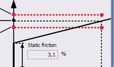
The coulomb friction (induding gravity factor, etc.) and viscous friction coeffióent of a bali screw or a are estimated after operating an arbitrary operation pattern.
Friction torgue
Upper threshold Estimation value Lower threshold
Rated speed
r/min
4,1
%
%
%

|
-f- 1 1 |
Static friction |
j |
L |
Rated speed | ||
|
Alarm... o3 □ |
■ |
— |
% |
3000 | ||
r/min
330
130
'o' 0
41
"O
<11
i ■m
-330
-540

iii
Ready
[Station 00] MR-J4-B (-RJ) Standard Servo amplifier connection: USB
NUM
Wyszukiwarka
Podobne podstrony:
New ProjectatosO - ATOS Professional V8 File Edit View Acquisrtion Construct Inspection-
OuickTime Player 7 File Edit View Window Help E3 0 <S> V * <D ^ ■«» 56% New Project- P New
Bfigs19 FirstDialog - Microsoft Developer Studio File Edit View insert Project Build Jools Window He
file New Project & Open Project... Ctrl+N Ctrl+O Add Project... Remove Project O Save Project
file New Project & Open Project... Ctrl+N Ctrl+O Add Project... Remove Project O Save Project
nic mini m Dev-C++ 4.9.9*2 File Edit Searrh Vtew Project i New Open Project, or file.,. .Ctfl+O
12fg0004 Microsoft Visual Basic - Projectl [design] File Edit View insert Bun lools Ądd-lns Help Dft
12fg0005 Microsoft Visual Basic - Projectl [design]File Edit View insert FUin Jools Ądd-lns
12fg0016 Microsoft Visual Basic - Projectl [design] File Edit View insert FUin Jools Ądd-lns Help
12fg0028 _Microsoft Visual Basic - Project! [design] File Edit View insert Bun lools Ądd-lns Help Ad
select target O X [New ProjectSelect a Target Select the platform and configurattons you wlsh to dep
wgc2 iMicrosoft Project - WyposażenieMieszkaniaWStanieSurowym File Edit View Insert Format lools Pro
x3 razy X2 M FluidSIM-P File Edit Execute Library Insert Didactics Project View Options Window ?
E EnvisioneerTrial Version - [Projectl - Model] File Edit View Insert Tools Settings Window
więcej podobnych podstron