3784502366
Zeszyty Naukowe AMW — Scientific Journal of PNA

Rys. 4. Przekrój turbiny wysokiego ciśnienia silnika LM 2500 z dokumentacji okrętowej
Fig. 4. The cross-section ofthe LM 2500 engine high pressure turbinę taken from the ship's documentation

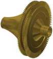
Rys. 5. Turbina wysokiego ciśnienia silnika LM 2500 zamodelowana w programie CAD
Fig. 5. The LM 2500 engine high pressure engine modeled in the CAD program
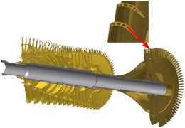
Oba stopnie turbiny wysokiego ciśnienia składają się z drążonych łopatek, które są chłodzone poprzez „kanały" wewnę-trze. Z uwagi na ich największą w całym modelu odległość od osi obrotu zostały one uwzględnione w budowie. Widok przekroju modelu wytwornicy spalin z powiększonymi łopatkami TWC został pokazany na rysunku 6.
Both stages in the high pressure turbinę are composed of hollowed blades, which are cooled by internal 'channels'. They were included in the model because they had the largest distance from the axis of rotation in the whole model. The view of the model cross-section of the com-bustion gas generator with enlarged blades TWC is shown in figurę 6.
2014(LV)

Rys. 6. Przekrój wytwornicy spalin silnika LM 2500 ze zbliżeniem szczegółu na drążenia łopatek turbiny sprężarki
Fig. 6. The cross-section of the combustion gas generator in the LM 2500 engine with a close-up detail focusing on the hollows in the compressor turbinę
13
Wyszukiwarka
Podobne podstrony:
Zeszyty Naukowe AMW — Scientific Journal of PNA Rys. 3. Symulacja stref działania stacji referencyjn
Zeszyty Naukowe AMW — Scientific Journal of PNA Zeszyty Naukowe AMW — Scientific Journal of PNA ■5T
Zeszyty Naukowe AMW — Scientific Journal of PNA 4. Podobną analizę należy przeprowadzić dla kilku st
Zeszyty Naukowe AMW — Scientific Journal of PNA aparatury sieci stacji referencyjnych. Należy pamięt
Zeszyty Naukowe AMW — Scientific Journal of PNA interesujących referatów [5, 7, 12, 26, 27] dotycząc
Zeszyty Naukowe AMW — Scientific Journal of PNA Z punktu widzenia formalnego koncepcję budowy w Pols
Zeszyty Naukowe AMW — Scientific Journal of PNA Ekspertyza miała wyłącznie charakter teoretyczny.
Zeszyty Naukowe AMW — Scientific Journal of PNA Z badań przeprowadzonych przez ICAO (International C
Zeszyty Naukowe AMW — Scientific Journal of PNA technicznej silnika LM 2500 oraz wy- technical docum
Zeszyty Naukowe AMW — Scientific Journal of PNA Tabela 4. Parametry modeli 3D przed i po optymalizac
Zeszyty Naukowe AMW — Scientific Journal of PNA po ich zakończeniu obydwa tory pomiarowe zostały
Zeszyty Naukowe AMW — Scientific Journal of PNA Zeszyty Naukowe AMW — Scientific Journal of
Zeszyty Naukowe AMW — Scientific Journal of PNA Turbina napędowa jest sześciostopniową turbiną osiow
Zeszyty Naukowe AMW — Scientific Journal of PNA Tabela 2. Długości łopatek wirnikowych oraz promieni
ZESZYTY NAUKOWE AKADEMII MARYNARKI WOJENNEJ SCIENTIFIC JOURNAL OF POLISH N AVAL AC AD EMY 2014 (LV)
2012, 8 (4), 297-310^ LogForum > Scientific Journal of Logistics < http://www.logforum.net p-I
Scientific Journals of the Maritime University of 2015,44 (116), 5 ISSN 1733-8670 (Printed) ISS
RADA NAUKOWA „STUDIA I MATERIAŁY TOWARZYSTWA NAUKOWEGO NIERUCHOMOŚCI" Scientific Council of the
więcej podobnych podstron