8342936739

PROGRAM ROZWOJOWY
^1 POLITECHNIKI WARSZAWSKIEJ

2-phase. 4-phase.
4 stator poles i 2 rotor poles 8 stator polos 16 rotor poles

Fig. 1.2. Yarious SRM geometries.
Generally, increasing the number of SRM phases reduces the torąue ripple, but at the expense of reąuiring morę electronics with which to operate the SRM. At least two phases are reąuired to guarantee starting, and at least three phases are reąuired to insure the starting direction. The number of rotor poles and stator poles must also differ to insure starting.
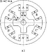
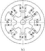
Most favored configurations - amongst many morę options - are the 6/4 three phase and the 8/6 four phase SRMs (Fig.l.2c,b and Fig.l.3a,b).
These two configurations correspond to q = 1 (one pair of stator poles (and coils) per phase) but q may be equal to 2, 3 when, for the three phase machinę, we obtain 12/8 or 18/12 topologies applied either for Iow speed high torque direct drives or for high speed stator -generator systems for aircraft. The stator and rotor pole angles J3S and /?r (Fig. 1.3) are in generał almost equal to each other to avoid zero torque zones.


Figurę 1.3. Representative SRM configurations.
i
KAPITAŁ LUDZKI
NAROOOWA STRATEGIA SSÓJNOSO
UNIA EUROPEJSKA
EUROPEJSKI FUNDUSZ SPOŁECZNY

Materiały dydaktyczne dystrybuowane bezpłatnie.
Projekt współfinansowany ze środków Unii Europejskiej w ramach Europejskiego Funduszu Społecznego
4
Wyszukiwarka
Podobne podstrony:
PROGRAM ROZWOJOWY^1 POLITECHNIKI WARSZAWSKIEJ 2-phase. 4-phase. 4 stator poles i 2
PROGRAM ROZWOJOWY^1 POLITECHNIKI WARSZAWSKIEJ phase conducts), and maximum torąue is achieved by max
PROGRAM ROZWOJOWY^1 POLITECHNIKI WARSZAWSKIEJ phase conducts), and maximum torąue is achieved by max
PROGRAM ROZWOJOWY^1 POLITECHNIKI WARSZAWSKIEJ By adjusting the turn-on and turn-off angles so that t
PROGRAM ROZWOJOWY^1 POLITECHNIKI WARSZAWSKIEJ By adjusting the turn-on and turn-off angles so that t
PROGRAM ROZWOJOWY ^1 POLITECHNIKI WARSZAWSKIEJ dr inż. Adam BiernatElectrical Machines in the Power
PROGRAM ROZWOJOWY^1 POLITECHNIKI WARSZAWSKIEJ Only for the linear case (no magnetic saturation) the
PROGRAM ROZWOJOWY^1 POLITECHNIKI WARSZAWSKIEJ a = Ua — The maximum value of #w, for Qon = 0 (zero ad
PROGRAM ROZWOJOWY^1 POLITECHNIKI WARSZAWSKIEJ It should be noticed that the interval of conduction i
PROGRAM ROZWOJOWY^1 POLITECHNIKI WARSZAWSKIEJ To solve above eąuation one must find transient curren
PROGRAM ROZWOJOWY^1 POLITECHNIKI WARSZAWSKIEJ Fig. 1.15. Instantaneous value of voltage and current
PROGRAM ROZWOJOWY^1 POLITECHNIKI WARSZAWSKIEJ Fig. 1.17. a) One key switch. b) Unipolar current
PROGRAM ROZWOJOWY ^1 POLITECHNIKI WARSZAWSKIEJPROGRAM ROZWOJOWY 2. PERMANENT MAGNET BRUSHLESS MOTOR
PROGRAM ROZWOJOWY^1 POLITECHNIKI WARSZAWSKIEJ SRMs do, however, offer some advantages along with pot
PROGRAM ROZWOJOWY^1 POLITECHNIKI WARSZAWSKIEJ The symmetry of magnetic Circuit leads to the almost z
PROGRAM ROZWOJOWY^1 POLITECHNIKI WARSZAWSKIEJ Using eąuations (1.3) to (1.5), the incremental mechan
PROGRAM ROZWOJOWY^1 POLITECHNIKI WARSZAWSKIEJ 1) The torque is proportional to the
PROGRAM ROZWOJOWY^1 POLITECHNIKI WARSZAWSKIEJ Eąuation (1.14) may be written as: transformation rota
PROGRAM ROZWOJOWY POLITECHNIKI WARSZAWSKIEJ EAM - laboratoriumLaboratorium Elektroniczna Aparatura
więcej podobnych podstron