7412533623
Tube-Transistor “Carrier Switch”
By DAVE STONE
/Use power linę for remołe conłrol wiłh łhis easy-ło-build and easy-ło-align carrier-current łransmiłłer and receiver.
CARRIKR reccivcr and transmittcr systcms are “old hat" in the field of elect ronić remote-control de-vices. They are a time-tested means of using the power lines to carry a trans-mitted low-power. low-frequency radio signal to operate a remotely located re-ceiver relay unit. The receiver relay set can operate other electronic equip-ment, turn on motors, lights. open garage doors and. in generał, conłrol many other types of appliances which need to be turned on or ofT.
Today’s miniaturę components lend themsehes readily to the construction of compact transmitters and sensitive receivers for carrier-control work. This transmitter-receiver combination is un-complicated, easy to construct and align. and is very reliable for operation over moderate distances. It uses standard components and best of all. it calls for easily obtained TV replacement width coils for the tuned circuits so coil winding is unnecessary. The fre-quency can be varied from approxi-mately 60 to 80 kc. and the Iow power output of the transmitter precludes in-terfering radiation from the power linę.
Circuit
The transmitter uses a 6AQ5 in an electron-coupled oscillator Circuit, as shown in Fig. 2. This Circuit arrange-ment is very stable and tends to keep power-line yariations from loading and affecting the oscillator freąucncy. Lx with C, forms the tuned tank Circuit for the oscillator section. with feed-back obtained from the cathode winding into the grid Circuit. The piąte tank Circuit. La-Ca, tunes to the same frequency established by the grid tank and couples the signal out to the power linę via L»'s secondary. Cs blocks the a.c. linę from being short-circuited through the secondary winding and RFC i keeps the r.f. output from being shunted by the power transformers primary winding. This insures that all the output is sent into the linę.
The transmitter power supply is compact, consisting of a smali power transformer, selenium rectifier, and miniaturę elect rolytics. The trans-mitted signal is simply turned on and off with the “Carrier On-OfT” switch S, which applies “B + ” to the 6AQ5*s screen grid and piąte. R, is the filter resistance and R- provides bleeder ac-tion by serving as a constant load to the power supply when the “B-f” is disconnected in the "Carrier Off" po-sition.
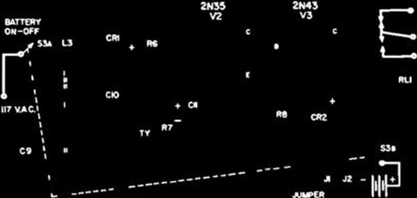
The transmitted signal enters the receiser (Fig. 1) through the tuned Circuit La-Ci- and is detected by the 1N34A germanium diodę. The amount of rectified signal applied to the base of the 2N35 n-p-w transistor is con-trolled by the “Sensitivity" potenti-ometer. The two transistors are con-nected as a d.c. amplifier Circuit and the resulting amplified current in the collector of the 2N43 p-n-p transistor operates the 8000-ohm sensitive relay. The 1N69 germanium diodę in the emitter of the second transistor pro-

81
Ri—1000 ohm. V2 »*•
Rj—10*000 ohm linttr laper carbon poi R*—4700 ohm, l/2 w. rei.
Ci—.01 m/-. 600 V. dii€ capecUor Ci*—}00 600 y. diic Cćpacitor
Cir-~f ^ minisiure eltc. capaeitor CRr—lN)4A ltrmenium diodę CRr—lN69 germanium diodę
Alt/—S.p.d.l. 8000-ohm temiliye relay (Sigma 8000 CDS or equi*aleni) ii. Jr—Pin ieck Br—9-12 v. baitery Sr—D.p.d.l. loggie swileh
Vi-fn.p.n" iramiitor (2Nif)
Vs—“p~n.p" iramiitor (2N4i)
Fig. 1. Circuit oi the transistorized carrier-current receieer. ►
Front views oi the complete carrier-current unit with the transmitter at left and the receirer at the right in this photograph.
ELECTRONICS WORLD
64
4 «
Wyszukiwarka
Podobne podstrony:
Małgorzata MieszekMałgorzata Mieszek, “Carmen nuptiale” by Jan Bielski as an example ofJesuit writin
3 f7909d9181 NOTICE This manuał was written by the Yamaha Motor Company primarily for use by Yamaha
mk2 p30 Order by Do not use No. PKICK SPARKS PART No. DESCKIITION Ol PAKI JCT
mk2 p14 er by ARES I>o not use No. PART No. DESCRIPTION OF
mk2 p15 Order by Do not use No. PRICE SPARES PART No. DBSCRIPTION Ol- PART perśot KACU No. L
mk2 p28 Order by Do not use No. PRICE SPAKKS PAKT No. DKSCKIPTION OF PAKI
mk2 p29 Order by Do not use SI*ARES PART No. No. 5716 37
mk2 p33 Order by Do not use No. PRICE SPARES PART No.
credits pcx GOES TO SCHOOL T. prograM by...........Dave Krohne artwork by...........Stephen Beat*
img166 (3) 22 22 CN: Use a light blue for D, black for F, and gray for H. (1) Do n
key0005 3. Use of English For questk>ns 31-40, read the text bełow and think of the word which be
show inter Press RETURN to get started! Switch>enable Switch#show interfaces FastEthernetO/1 is d
New Forms Taschen 055 by the Spanish engineer Santiago Calatrava for the Lyon-Satolas station, where
exam0005 3. Use of English For quesb or»s 31-40, read the text betów and think of the word wtiich be
Certificate Use thls award for your European Skills Passport ^geuropass An initative of the European
Movios Gcnre Sort by CaptainAmtfKo: T_ TheAfiunngSpider... Dtargcnt Nojti Nc«J for SpecdTHE WOLF OF
Transient Stability AnalysLs ofthe IEEE 9-Hus Electric Power SystemAbstract It k widel> accepted
24 Paweł Mąkosa all pupils in Poland will be able to use free e- coursebooks for 14 school subjects.
więcej podobnych podstron