Self-diagnosis of Motronic system
Reading measured value block: Display Groups 01 to 10
Display Group 01 - Basic function:
Notes on display zone 2:
l
◆
The maximum engine load drops by about 10 % for every 1000 m above sea level.
l
◆
The maximum engine load also drops by about 10 % when the outside temperature is very high.
l
◆
At full throttle the values will be at least:
approx. 7.0 ms at 4000 rpm
approx. 6.5 ms at 6000 rpm
Test table, Display Group 01
Test table, Display Group 01
Test table, Display Group 01
Note on display zone 3:
l
◆
When the accelerator is fully depressed the display will show a value of between 75 and 95<°.
Display Group 02 - Basic function:
Read measured value block 1
⇒
◂
Indicated on display
620...860
rpm
1.0....2.5
ms
0...5 <°
9...15 °
BTDC
Ignition timing
Throttle valve angle
Engine load (injection period per crankshaft revolution)
Idling speed shown in steps of 40 rpm
Four-wheel drive: 620...740 rpm
Front-wheel drive: 740...860 rpm
Display zone
Readout on V.A.G 1551
Cause of fault
Fault remedy
1
less than 620 rpm
or
less than 740 rpm
- Throttle valve control part -J338 sticking or
defective
- Test throttle valve control part -J338 => Page
24-81
more than 740 rpm
or
more than 860 rpm
- Idling speed switch -F60 not closed (defective)
- Interrogate fault memory
=> Page
01-7
- Large quantity of unmetered air (idling speed
stabilisation cannot compensate)
- Rectify leak (unmetered air)
- Throttle valve control part -J338 sticking or
defective
- Test throttle valve control part -J338 => Page
24-81
Display zone
Readout on V.A.G 1551
Cause of fault
Fault remedy
2
less than 1.0
- Values of less than 1.0 can only occur when
driving on overrun
more than 2.5
- Rough idling (engine not running on all cylinders)
- Injector or spark plugs defective
- Air mass meter -G70 defective
- Interrogate fault memory
=> Page
01-7
- Throttle valve control part -J338 defective
- Test throttle valve control part -J338 => Page
24-81
- Electrical consumers on
- Switch off consumers
- Steering wheel on full lock
- Return steering wheel to centre
- Drive position engaged (automatic gearbox)
- Move selector lever to P or N
Display zone
Readout on V.A.G 1551
Cause of fault
Fault remedy
3
less than 0 <°
- Not possible
more than 5 <°
- Adaption of throttle valve control part -J338 not
performed
- Perform adaption of throttle valve control part -
J338
=> Page
01-7
- Throttle valve potentiometer in throttle valve
control part -J338 defective or incorrectly set
- Test throttle valve control part -J338 => Page
24-81
- Accelerator cable setting
- Adjust accelerator cable
- Throttle valve sticking
- Rectify fault
Read measured value block 2
⇒
◂
Indicated on display
620...860
rpm
1.0...2.5
ms
1.0...4.0
ms
3.0...5.0
g/s
Intake air mass
Injection period per engine cycle
Engine load - see Display Group 01
Idling speed shown in steps of 40 rpm
Four-wheel drive: 620...740 rpm
Front-wheel drive: 740...860 rpm
Strona 1 z 7
Test table, Display Group 02
Test table, Display Group 02
Note on Display Group 02:
l
◆
Display zone 2 shows the injection period corresponding to the intake air mass and the engine load when idling. The value is a calculated (i.e.
theoretical) value which for technical reasons only relates to a single crankshaft revolution. The engine load when idling is the load created by the internal
friction which the engine has to overcome and the power required to drive the ancillaries. The intake air mass is shown in display zone 4.
l
◆
Display zone 3 shows the injection period for a complete engine cycle, i.e. two crankshaft revolutions.
l
◆
However, the value shown in display zone 3 is a corrected value corresponding to the actual injection period. It will not be double the value shown in
display zone 2. The correction takes into account factors such as the following:
- Lambda mixture control
- Fuel intake from the activated charcoal filter
- Air density, air temperature
- Voltage of electrical system (faster or slower opening of injectors)
l
◆
For example, if the engine takes in unmetered air, only the calculated value in display zone 2 (injection period per crankshaft revolution) should change.
The lambda mixture control will ensure that the actual injection period per complete engine cycle remains at the specified value.
Notes continued:
Note on display zone 4:
l
◆
The value displayed is the air mass as measured by the air mass meter.
l
◆
If the emergency running mode is engaged as a result of a fault in the throttle valve control part, the engine will run without idling speed stabilisation at
a higher idling speed which is determined by the emergency running slot (between about 1100 and 1300 rpm). The air flow rate will be between about 4.5
and 5.5 g/s.
l
◆
If the engine control unit detects a fault in the air mass meter, the substitute value from the throttle valve potentiometer will be displayed in grammes per
second (g/s).
DIsplay Group 03 - Basic function:
Note on display zone 3:
When a fault relating to the coolant temperature sender -G62 is stored in the fault memory, the engine control unit will use the intake air temperature as a
substitute value when the engine is started. The temperature will then rise according to a model curve which is pre-programmed in the control unit. After a
specific time it will assume a fixed substitute value for a normal engine operating temperature. This fixed substitute value also depends on the intake air
temperature.
Note on display zone 4:
It is not possible to give specified values as the display readout is heavily affected by the ambient temperature.
Test table, Display Group 03
Display zone
Readout on V.A.G 1551
Cause of fault
Fault remedy
1
- See Display Group 01, display zone 1 => Page
01-
98
2
- See Display Group 01, display zone 2 => Page
01-
98
Display zone
Readout on V.A.G 1551
Cause of fault
Fault remedy
3
less than 1.0
- Large quantity of fuel from activated charcoal
filter system (ACF)
- Test solenoid valve for activated charcoal filter
=>Page
24-77
- Wrong type of injectors fitted (delivery rate too
high)
- Check injection quantity
=> Page
24-42
more than 4.0
- Increased engine load (electrical consumers on, air
conditioner on, drive position engaged or power
steering on full lock)
- Remove load
4
less than 3.0
- Large quantity of unmetered air between intake
manifold and air mass meter
- Rectify leak (unmetered air)
more than 5.0
- Drive position engaged (automatic gearbox)
- Move selector lever to P or N
- Increased engine load due to ancillaries
- Remove load (e.g. air conditioner, power
steering)
Read measured value block 3
⇒
◂
Indicated on display
620...860
rpm
10..14.5
V
80..105
°C
...
°C
Intake air temperature
Coolant temperature
Battery voltage
Idling speed shown in steps of 40 rpm
Four-wheel drive: 620...740 rpm
Front-wheel drive: 740...860 rpm
Strona 2 z 7
Test table, Display Group 03
Display Group 04 - Idling speed stabilisation:
Test table, Display Group 04
Note on display zone 1:
When the accelerator is fully depressed the display will show a value of between about 75 and 95<°.
Note on display zones 2 and 3:
l
◆
The display shows how far the learning process has caused the idling speed stabilisation to drift away from the mean level that was originally set at the
factory. With a new engine this will be a positive value (because of the higher friction); in an engine that has already been run in it will be a negative value.
A value of -70 g/s combined with an excessively low value in Display Group 5, display zone 3, indicates the presence of unmetered air.
l
◆
The value displayed is calculated on the basis of information from the throttle valve potentiometer. It is not measured by the air mass meter.
l
◆
On vehicles with manual gearbox, display zone 3 will always show a value of 0.
Note on display zone 4:
The following operating states are shown:
l
◆
Idling
l
◆
Part throttle
l
◆
Full throttle
l
◆
Overrun
l
◆
Enrichment (full-throttle enrichment)
Display Group 05 - Idling speed stabilisation (idling):
Display zone
Readout on V.A.G 1551
Cause of fault
Fault remedy
1
- See Display Group 01, display zone 1 => Page
01-
98
2
less than 10 V
- Alternator defective, battery charge very low
- Test voltage and charge battery
- Heavy demand on electrical system shortly after
starting due to high charging current and ancillaries
- Increase revs for a few minutes and switch off
ancillaries
- Contact resistance in power supply or earth
connection for engine control unit
- Test power supply to engine control unit =>
Page
28-25
- Current drain when ignition is switched off
- Eliminate current drain
more than 14.5 V
- Voltage regulator in alternator defective
- Test voltage and if necessary fit a new regulator
- Excess voltage from assisted start or rapid
charging
- Interrogate fault memory
=>Page
01-7
Display zone
Readout on V.A.G 1551
Cause of fault
Fault remedy
3
less than 80°C
- Engine too cold
- Take vehicle for test drive
- Coolant temperature sender or wiring to engine
control unit
- Test coolant temperature sender
-G62 =>Page
28-22
more than 105°C
- Radiator dirty
- Clean radiator
- Radiator fan not working
- Check operation
- Thermostat defective
- Test thermostat
- Coolant temperature sender or wiring to engine
control unit
- Test coolant temperature sender
-G62 => Page
28-22
4
constant 25.5°C
- Fault recognised in intake air temperature sender -
G42
- Interrogate fault memory
=>Page
01-7
- Intake air temperature sender -G42
- Test -G42
=>Page
28-12
Read measured value block 4
⇒
◂
Indicated on display
0....5
<°
-0.7...+0.7
g/s
-0.7...+0.7
g/s
Idling
Operating state (idling, part/full throttle, enrichment, overrun)
Idling speed air mass, learned value (manual gearbox in neutral; automatic gearbox with selector lever in
position P or N)
Idling speed air mass, learned value (automatic gearbox with drive position engaged)
Throttle valve angle
Display zone
Readout on V.A.G 1551
Cause of fault
Fault remedy
2
less than -0.7 g/s
- Unmetered air downstream of throttle valve
- Rectify leak (unmetered air)
more than +0.7 g/s
- Increased load due to ancillaries
- Switch off air conditioner and electrical
consumers
- Constriction or foreign bodies
- in intake tract
- Eliminate constriction or foreign bodies
Read measured value block 5
⇒
◂
Indicated on display
620...860
rpm
xxxx
rpm
-10...+10
%
3.0...5.0
g/s
Air mass
Idling speed control
Strona 3 z 7
Note on display zone 2:
The specified engine speed from engine control unit (calculated in control unit ) is displayed.
Note on display zone 3:
l
◆
The change in air mass during idling is shown as a percentage. As soon as the change has been compensated for by the idling speed stabilisation learning
process, the mean value is restored. The amount of deviation from the mean value depends on the extent of the load change (e.g. as a result of switching
electrical consumers on or off).
Notes continued:
l
◆
The air mass requirement varies with changing load conditions during idling, even though the engine speed remains the same.
l
◆
The learning process proceeds in small stages each time the idling speed switch closes. If the deviation is large, several stages are required. In such cases
the accelerator must be blipped at intervals of approx. 20 seconds. Each blip activates a further stage in the learning process.
l
◆
The amount by which the learned value has "drifted away" is then shown in Display Group 04, display zone 2. The values from the idling speed control
remain outside the tolerance if the learned values in Display Group 04, display zone 2, have reached the limits of adjustment (stop values).
l
◆
Stop values: -1.70 and +1.70 g/s
Display Group 06 - Idling speed stabilisation:
Test table, Display Group 06
Note on display zone 3:
l
◆
The readout should fluctuate around 0. If the display shows a constant 0, this means that the lambda mixture control has switched from closed-loop
control to open-loop control because of a fault in the lambda control function. Interrogate the fault memory => Page
01-7
.
l
◆
Lambda control operating status: check Display Group 21, display zone 4=>Page
01-135
.
Display Group 07 - Lambda learned values:
Notes on all display zones:
Low values indicate that the mixture is too rich and that the lambda control is leaning it down.
l
◆
High values indicate that the mixture is too lean and that the lambda control is enriching it.
l
◆
If the power supply to the control unit is interrupted, all the learned values will be reset.
l
◆
(add) = additive; the fault (e.g. unmetered air) becomes less noticeable as the engine speed increases. With additive learned values the injection period is
adjusted by a fixed amount which is not dependent on the basic injection period.
Engine speed (specified) shown in steps of 10 rpm
Four-wheel drive: 720 rpm
Front-wheel drive with automatic gearbox, selector lever in P or N: 800 rpm
Front-wheel drive with automatic gearbox, drive position engaged: 770 rpm
Front-wheel drive with manual gearbox: 800 rpm
Engine speed (actual) shown in steps of 10 rpm
Display: max. 2550 rpm in steps of 10 rpm
Four-wheel drive: 620...740 rpm
Front-wheel drive: 740...860 rpm
Read measured value block 6
⇒
◂
Indicated on display
620...860
rpm
-10...+10
%
-10...+10
%
-10...+10
%
Lambda control, Bank 2
Lambda control, Bank 1
Idling speed air mass, control value (idling speed control) - see Display Group 05
Engine speed (actual) shown in steps of 10 rpm
Display: max. 2550 rpm in steps of 10 rpm
Four-wheel drive: 620...740 rpm
Front-wheel drive: 740...860 rpm
Display zone
Readout on V.A.G 1551
Cause of fault
Fault remedy
3/4
Outside tolerance
range
- Negative value = mixture too rich.
- Result: lambda control leans out the mixture
- Positive value (+ sign not shown)
- = mixture too lean. Result: lambda control
enriches the mixture
- Wait 30 seconds until display has settled
- Unmetered air
- Rectify leak (unmetered air)
- Injector defective
- Check injection quantity
=> Page
24-42
- Lambda learned value at limit of adjustment
- Check lambda learned values
- see Display Group 07
Read measured value block 7
⇒
◂
Indicated on display
-10...+10
%
-10...+10
%
-10...+10
%
-10...+10
%
Lambda learned value for Bank 2 at idling speed (additive)
Lambda learned value for Bank 1 at idling speed (additive)
Lambda learned value for Bank 2 at part throttle (multiplicative)
Lambda learned value for Bank 1 at part throttle (multiplicative)
Strona 4 z 7
l
◆
(mul) = multiplicative; the fault (e.g. defective injector) becomes more noticeable as the engine speed increases. A multiplicative learned value is a
percentage factor by which the injection period is adjusted. This adjustment is dependent on the basic injection period.
Notes continued:
l
◆
If the fault reader shows differences of more than 15 % between the lambda learned values for cylinder banks 1 and 2, the following faults are possible:
- Spark plug defective
- Injector defective (leaking or blocked)
-Lambda probe defective or dirty
-Unmetered air on one side
- Basic mechanical setting (valve timing) of engine incorrect
Test table, Display Group 07
Test table, Display Group 07
Display Group 08 - Lambda learned values
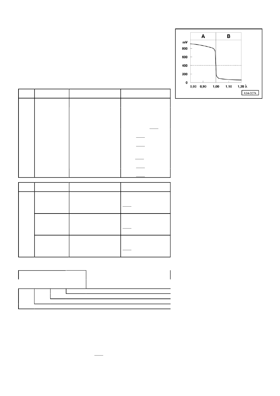
Display Group 09 - Lambda probe voltage:
Notes on display zones 1 and 2:
l
◆
The voltage signal "rich mixture (low level of residual oxygen)" is about 0.7...1.1 V.
l
◆
The voltage signal "lean mixture (high level of residual oxygen)" is about 0.0...0.3 V.
l
◆
The transition from "rich" to "lean" (λ = 1.0) is accompanied by a voltage jump from between 0.7 and 1.1 V to between 0.0 and 0.3 V, and vice versa.
Notes continued:
l
◆
Due to the steep voltage jumps the Lambda control cannot maintain the ideal mixture composition of λ = 1.0. The control fluctuates constantly between
conditions "slightly too lean" and "slightly too rich".
Display zone
Readout on V.A.G 1551
Cause of fault
Fault remedy
1/2/3/4
Low lambda
learned values
- Low lambda learned values at idling speed and
normal lambda learned values at part throttle; oil
may be diluted with petrol
- Disappears after motorway run or oil change
Display Group 09, display zones 1 and 2 => Page
01-119
- Injector leaking
- Test injector =>Page
24-38
- Fuel pressure too high
- Check fuel pressure
=> Page
24-32
- Solenoid valve 1 for activated charcoal filter -N80
constantly open
- Test -N80 => Page
24-76
- Air mass meter -G70 defective
- Test -G70 => Page
24-51
- Lambda probe heating defective or lambda probe
dirty
- Check lambda probe heating
=> Page
24-71
Display zone
Readout on V.A.G 1551
Cause of fault
Fault remedy
1/2/3/4
High lambda
learned values
- High lambda learned values for idling and lower
lambda learned values for part throttle; possibility
of unmetered air around intake manifold
- Rectify faults
Display Group 09, display zones 1 and 2 => Page
01-119
- Injector blocked
- Check injection quantity
=>Page
24-42
- High values in display zones 2 and 3; air mass
meter -G70 defective
- Test -G70 =>Page
24-51
- Fuel pressure too low
- Check fuel pressure =>Page
24-32
- Unmetered air between -G70 and throttle valve
- Rectify fault
- Unmetered air at manifold gasket
- Lambda probe heating defective or lambda probe
dirty
- Check lambda probe heating
=>Page
24-71
Read measured value block 08
⇒
◂
Indicated on display
620...860
rpm
1.00...3.00
ms
-10...+10
%
-10...+10
%
Lambda learned value for Bank 2 at idling speed (additive)
- see Display Group 07
Lambda learned value for Bank 1 at idling speed (additive)
- see Display Group 07
Injection period per engine cycle - see Display Group 02
Idling speed shown in steps of 10
Display: max. 2550 rpm in steps of 10
Four-wheel drive: 620...740 rpm
Front-wheel drive: 740...860 rpm
Read measured value block 9
⇒
◂
Indicated on display
0.00...1.00
V
0.00...1.00
V
0....99 %
0.6....1.1
Lambda correction factor with active fuel tank breather system
- see Display Group 10
Duty cycle of ACF solenoid valve 1 - see Display Group 10
Lambda probe voltage, Bank 2
Lambda probe voltage, Bank 1
Strona 5 z 7
l
◆
The displayed value must temporarily drop below 0.3 V and exceed 0.6 V. Displayed values of below 0.45 V indicate a lean mixture, and values of
above 0.45 V indicate a rich mixture.
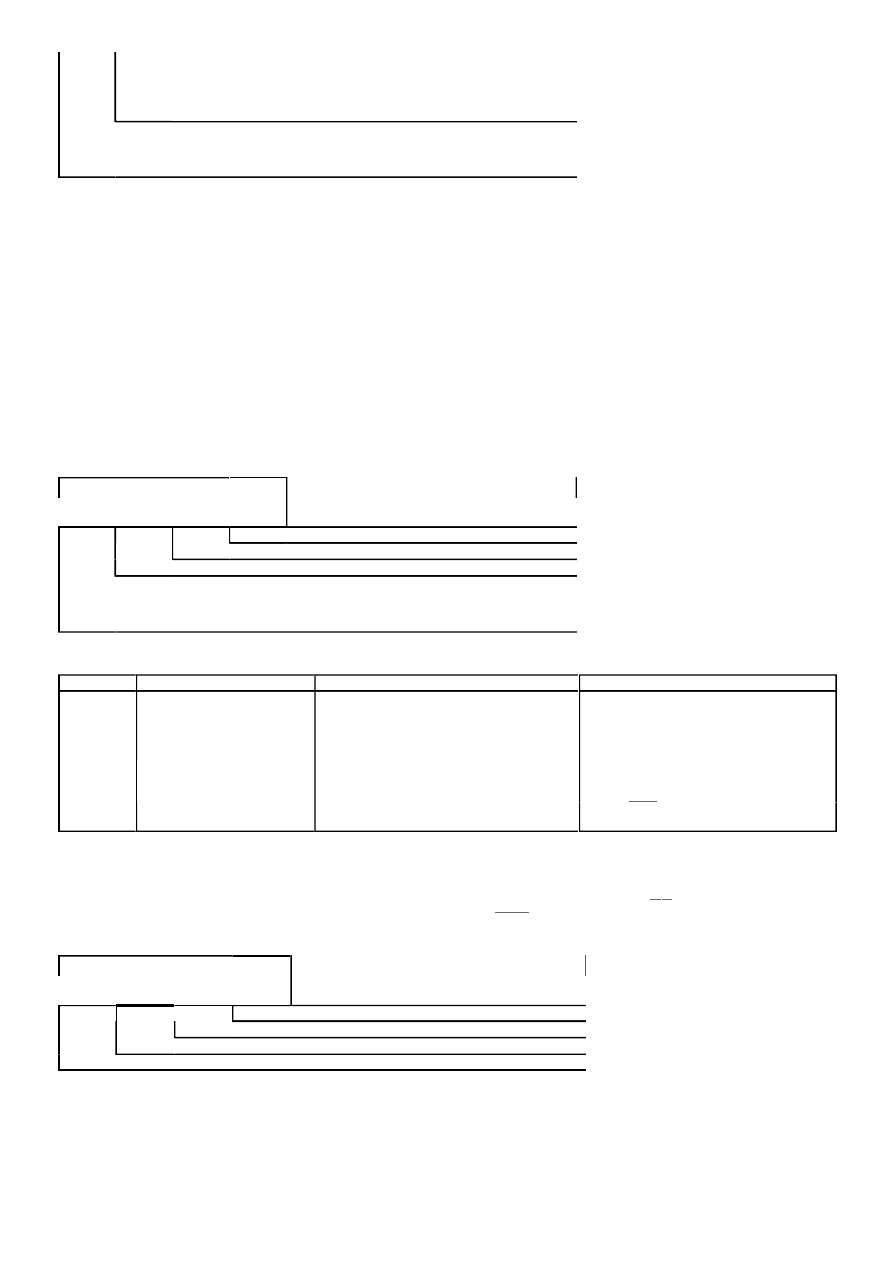
→ Lambda prove voltage Uλ in mV
A: High Lambda probe voltage
l
◆
Rich mixture (excess of fuel or shortage of air)
l
◆
Higher CO value
B: Low Lambda probe voltage
l
◆
Lean mixture (shortage of fuel or excess air)
l
◆
Lower CO value
Test table, Display Group 09
Display Group 10 - Fuel tank breather system:
Notes on Display Group 10:
l
◆
The engine control unit controls ACF solenoid valve 1 (-N80) as necessary to regulate the
amount of fuel vapour that is fed to the engine from the activated charcoal filter. If the
activated charcoal filter is relatively full and solenoid valve 1 is being kept closed (low duty
cycle) in order to maintain the specified purging rate, the lambda control will react by
adjusting the lambda correction factor. If in the meantime more fuel vapour has entered the
ACF system from the fuel tank and the adjustment is not enough, the control unit will
calculate a higher fill level.
l
◆
Testing fuel tank breather system=>Page
24-76
Notes continued:
Notes on display zone 1:
Display
zone
Readout on V.A.G
1551
Cause of fault
Fault remedy
1/2
Display constant
- Large quantity of unmetered
air
- Rectify fault
(between 0.0 and
0.3 V
- Spark plug defective
- Check spark plug
or
- Fuel system pressure too low
or too high
- Check fuel pressure
regulator and holding
pressure => Page
24-32
between 0.7 and 1.1
V)
- Injector defective
- Test injectors
=> Page
24-38
- Coolant temperature sender -
G62
- Interrogate fault memory
=> Page
28-22
- Solenoid valve 1 for
activated charcoal filter -N80
- Perform final control
diagnosis
=>Page
24-76
- Lambda probe heating not
working
- Check lambda probe heating
=> Page
24-71
- Lambda probe defective or
dirty
- Interrogate fault memory
=> Page
24-67
Display
zone
Readout on V.A.G
1551
Cause of fault
Fault remedy
1/2
Constant 1.105 V
- Short circuit to positive in:
- - Lambda probe
- - Signal wire
- - Earth wire
- - Engine control unit
- Test lambda probe => Page
24-67
Constant value
between 0.400 and
0.500 V
- Open circuit in:
- - Lambda probe -G39
- - Signal wire
- - Earth wire
- - Engine control unit
- Test lambda probe => Page
24-67
Constant 0.000 V
- Short circuit to earth in:
- - Lambda probe -G39
- - Signal wire
- - Earth wire
- - Engine control unit
- Test lambda probe => Page
24-67
Read measured value block
10
⇒
◂
Indicated on display
0...99
%
0.6...1.1 -5...+95 0.50...1.50
Purging rate of fuel tank breather system
Fill level of activated charcoal filter
Lambda correction factor with active fuel tank breather system
Duty cycle of solenoid valve 1 for activated charcoal filter -N80
Strona 6 z 7

l
◆
When the lambda control cuts in, ACF solenoid valve 1 (-N80) is opened for a period of
about 220 to 900 seconds (fuel tank breather system on) followed by an inactive period of
about 1 minute (fuel tank breather system off). During the 70 seconds or so of non-activity the
lambda control learns the engine operating conditions without the influence of the fuel vapour
from the activated charcoal filter.
l
◆
A duty cycle of 0 % means that ACF solenoid valve 1 is closed. A duty cycle of 99 %
means that it is fully open.
l
◆
When the engine is idling it can only use a certain quantity of fuel vapour from the
activated charcoal filter system. The degree to which ACF solenoid valve 1 is opened at idling
speed is therefore limited. At part throttle and full throttle the duty cycle can increase to as
much as 99 %.
l
◆
The influence of the activated charcoal filter system can be determined by comparing the
the values shown on the fault reader display in "Basic setting" mode (solenoid valve 1 closed)
with those shown in "Read measured value block" mode (solenoid valve 1 open for between
about 220 and 900 seconds and closed for about 70 seconds).
l
◆
By pressing the keys 4 and 8 on the V.A.G 1551 (or V.A.G 1552) it is possible to switch
back and forth between function 04 ("Basic setting") and function 08 ("Read measured value
block").
Notes continued:
Notes on display zone 2:
l
◆
If the activated charcoal filter system is supplying a very rich mixture, this must be leaned
down by the lambda control. The display value for leaning down can be anything up to 0.6,
which would indicate that the lambda control has to reduce the injection quantity by 40 %.
l
◆
A display value of 1.0 (lambda control at neutral level, i.e. no correction factor) indicates
either that the activated charcoal system is supplying an ideal mixture (i.e. no enrichment or
leaning down necessary) or that ACF solenoid valve 1 is closed (=>display zone 1).
l
◆
A display value of between 1.01 and 1.10 indicates that the mixture being supplied by the
activated charcoal filter system is too lean. This means that the lambda control has to enrich it.
Notes on display zone 3:
l
◆
A display value of -5 indicates that there is no fuel vapour in the activated charcoal filter.
l
◆
A display value of +95 indicates that the activated charcoal filter is completely full of fuel
vapour.
Notes on display zone 4:
l
◆
The display shows the percentage of the overall intake volume which is being supplied by
the ACF system.
l
◆
A display value of 0.50 indicates that nothing is being supplied by the ACF system
(solenoid valve 1 closed).
l
◆
A display value of 1.50 indicates that 30 % of the intake air mass is being supplied by the
ACF system.
Strona 7 z 7
Wyszukiwarka
Podobne podstrony:
Opis grup silnika 2 8 ACK 2
Opis Grup Silnika Silniki ABZ AEW AKG AKJ AHC AKH
Opis Grup Silnika Silniki AGA AJG ALF ALW
opis kodów silnika 2,5 V6 opel
Opis wtyczki silnika E28 M535i
Opis wtyczki silnika E30 325i 1986
Opisy Grup Silników VAG EN
Opis silnikow krokowych id 3370 Nieznany
silnik Y22XE opis
ch-ka szybkościowa regulatorowa ZS opis, SiMR, Laboratorium Silników spalinowych
Opis poszczególnych grup metodycznych
Opis metodyki poszczeglnych grup wiekowych, ===HARCERSTWO===, metoda harcerska i system wychowawczy
Opis poszczególnych grup metodycznych
więcej podobnych podstron