Fias Co Farm
www.fiascofarm.com
Copyright© - 2011 Molly Nolte
Page 1 of 6
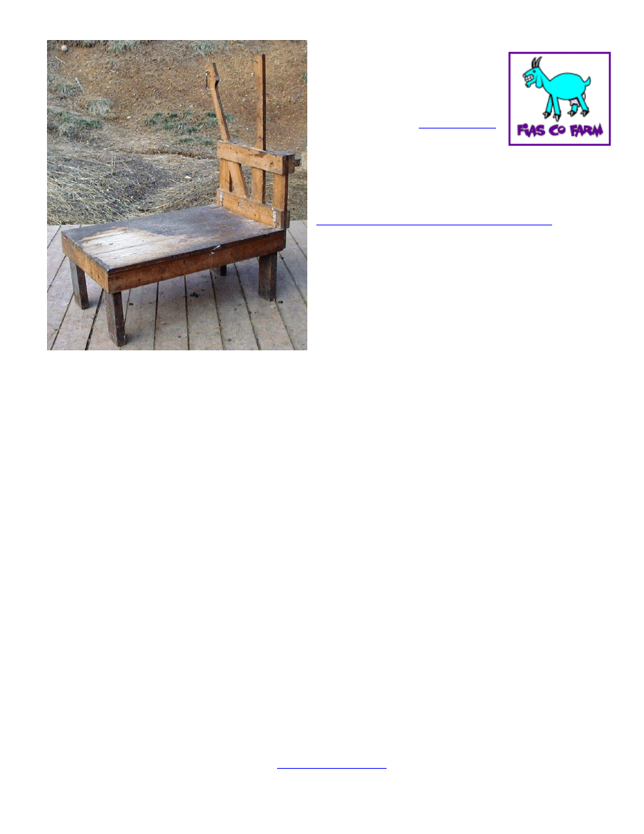
Milk Stand / Goat
Stand Plans
Brought to you by
Copyright© - 2011 Molly Nolte
If you construct this stand, please make a
donation to the Fias Co Farm web site to help
support all the free information it provides.
http://fiascofarm.com/contact.htm#support
Or send a donation check to:
Molly Nolte
4659 Seneca Drive
Okemos, MI 48864
Tools needed:
Saw
Jig Saw
Phillips Screwdriver
Tape Measure
Hammer
Square
Sand Paper/Sander
Drill with bits:
1/8”,
3/32”, 5/32”, 11/32”, 11/16
Hints:
Note that lumber is not actually the size it is called. For example, a 2X4 is not
really 2 inches by 4 inches.
Read and understand the entire step before actually doing it.
Predrill holes before screwing
using the 1/8” bit.
When attaching the wood together with your screws, make sure not to hit any
screws or tacking nails that you have already driven in from the other side.
Material list:
Lumber
(note: we do not use pressure treated lumber)
1” x 8” x 10’
parts A
Cut into three 36
“ pieces
(2)
1” x 4” x 6’
parts B & F Cut into four 36
“ pieces
1” x 4” x 8’
parts C & E
Cut into two 20 1/2 “ pieces & two 18 ½” pieces
1” x 4” x 8’
parts G & H
Cut into four 21 ½” pieces & two 4 ½” pieces
2” x 2” x 6’
parts J
Cut into three 20 ½” pieces
2” x 4” x 6’
parts D
Cut into four - 14
” pieces*
*Parts D are the legs and their length may be adjusted, longer or shorter, if desired.
The legs may be made from pressure treated wood if you wish.
Fias Co Farm
www.fiascofarm.com
Copyright© - 2011 Molly Nolte
Page 2 of 6
Material list continued:
Box
2” Exterior “deck” screws
(4) 3” Exterior “deck” screws
A couple dozen 1 1/2
” Exterior “deck” screws
(2)
3” Corner Brace with screws (also called corner brackets)
(1)
¼” x #20 x 2 ½ slotted round head machine screw
(1) ¼” wing nut
(1) ¼” x #20 hex nut
(2) ¼” flat washers
(1) 4” hook and eye latch with extra eye
Handful
of 1” finish nails (for tacking)
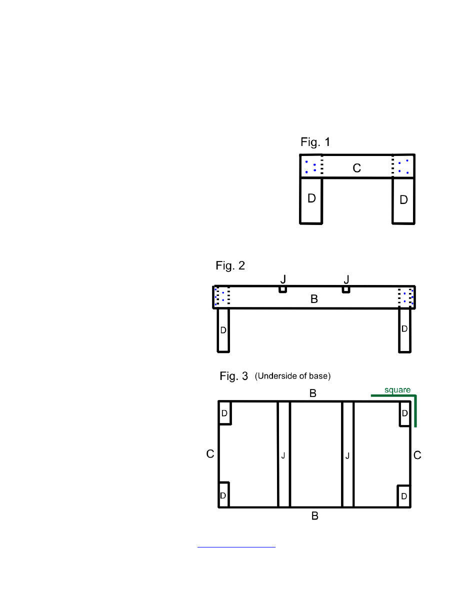
Constructing the Base:
1. Lay 2
legs (2” x 4” x 12”)
part (D) (Fig. 1) down with
one 20 1/2 “ end piece (C)
across the top, flush with
the top ends. Secure with
2” screws. Repeat process
for opposite end.
2. A
ttach both sides (B) 1” x
4” x 36” (Fig. 2) with 2”
screws.
3. Attach braces (J
), 2” x 2”
x 20” to the 1” x 4” sides
(parts B) (see Fig. 2 & 3)
flush with the top of parts
(B)
and 12” apart using
2” screws through parts
(B) into parts (J).
4. Check base for square
(Fig. 3). Adjust if
necessary.
Fias Co Farm
www.fiascofarm.com
Copyright© - 2011 Molly Nolte
Page 3 of 6
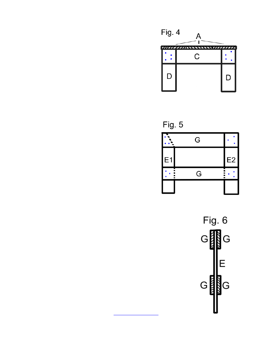
5. Screw three
1” x 8” x 36” pieces (A) to base
(Fig. 4) . Keep square as you go. Screw
around edges and to the braces using the 1
½” screws.
6. Sand all edges and round off corners.
Constructing the Head Gate:
1.
Cut one 18 ½” piece (E1) as follows:
From one corner, measure over and mark
the width at the top at 3”. From the same
corner, measure down the l
ength 5 ½” and
mark. Draw a line from the first mark to the
second and cut. See Fig. 5 left side part
E1 has a black dotted line indicating this
angle cut.
2.
Lay out the two 18 ½” pieces (E1 & E2) and place two 21 ½”
pieces
(G) across, with top flush and bottom 4” from ends of
part (E) (Fig. 5).
Use 1” finish nails to tack structure in place
without going through the other side. Turn over and put two
more 21 ½” pieces (G) into place in the same manner. In
effect “sandwiching” the (E) parts.
See Fig. 6
– This is what it should look like.
Secure with
2” screws from both sides - Indicated by blue
dots is Fig. 5. NOTE: Use an opposite triangle pattern on
the reverse side so you do not hit the screws coming from
the other side.
Fias Co Farm
www.fiascofarm.com
Copyright© - 2011 Molly Nolte
Page 4 of 6
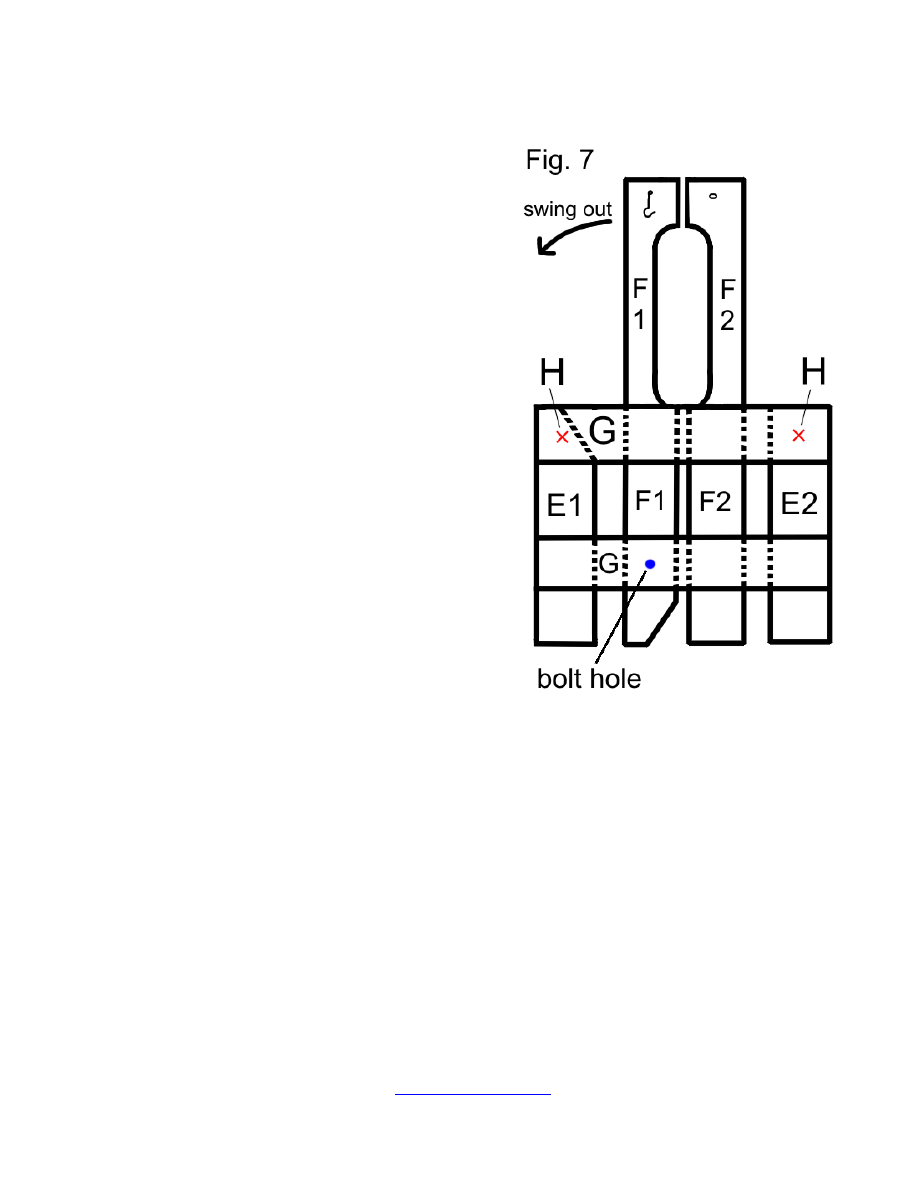
3.
Cutting the “Head hole”: (Refer to Fig.
7.) Cut a notch in two of the
1” x 4” x
36” (F1 & F2) beginning 4” from the top
and down 13 ½” from the first cut with a
depth of 1 ½”. Cut entrance and exit in
a curve that will not bind your jigsaw
4. Cut the bottom of (F1) as follows:
From the inside corner (same side as
the head hole- see Fig. 7
), measure 3”
across width and mark. From the same
corner measure up the length
4 ½” and
mark. Draw a line from mark to mark
and cut. This piece (F1) is the movable
portion of the head gate. Sand well so
no splinters are present and parts
move easily.
5. Insert and slide the part (F2) (not cut at
an angle on the bottom) between parts
(G). Place
½” from center on (G) and
4” below bottom part (G). Secure with
2” screws.
6. Slide part (F1) into the head catch (see
fig. 7). Make sure it has been sanded
enough to allow free movement within the head gate. L
ine up part (F1) 1” from
part (F2) already installed.
7.
Drill a hole with a 11/32” bit through the lower part (G), (Fig. 7), part (F1) that
moves, and part (G) on opposite side.
Use a 13/16” bit to enlarge the hole on
both sides on both sides no more than ¼” deep. This allows ¼” x 20 x 2 ½”
slotted round sc
rew with ¼” x 20 hex nut to be recessed. Install the bolt: place
o
ne ¼” washer on the 2 ½” slotted round crew, place screw though bolt hole,
place another washer on the screw and then the hex nut. Tighten.
8.
Attach 1” x 4” x 4 ½” (H) to upper part (G) (Fig. 7) at the “X” marks that will face
away from the base of the stand. Predrill holes to keep these parts from splitting
and attach
with 2” screws.
Fias Co Farm
www.fiascofarm.com
Copyright© - 2011 Molly Nolte
Page 5 of 6
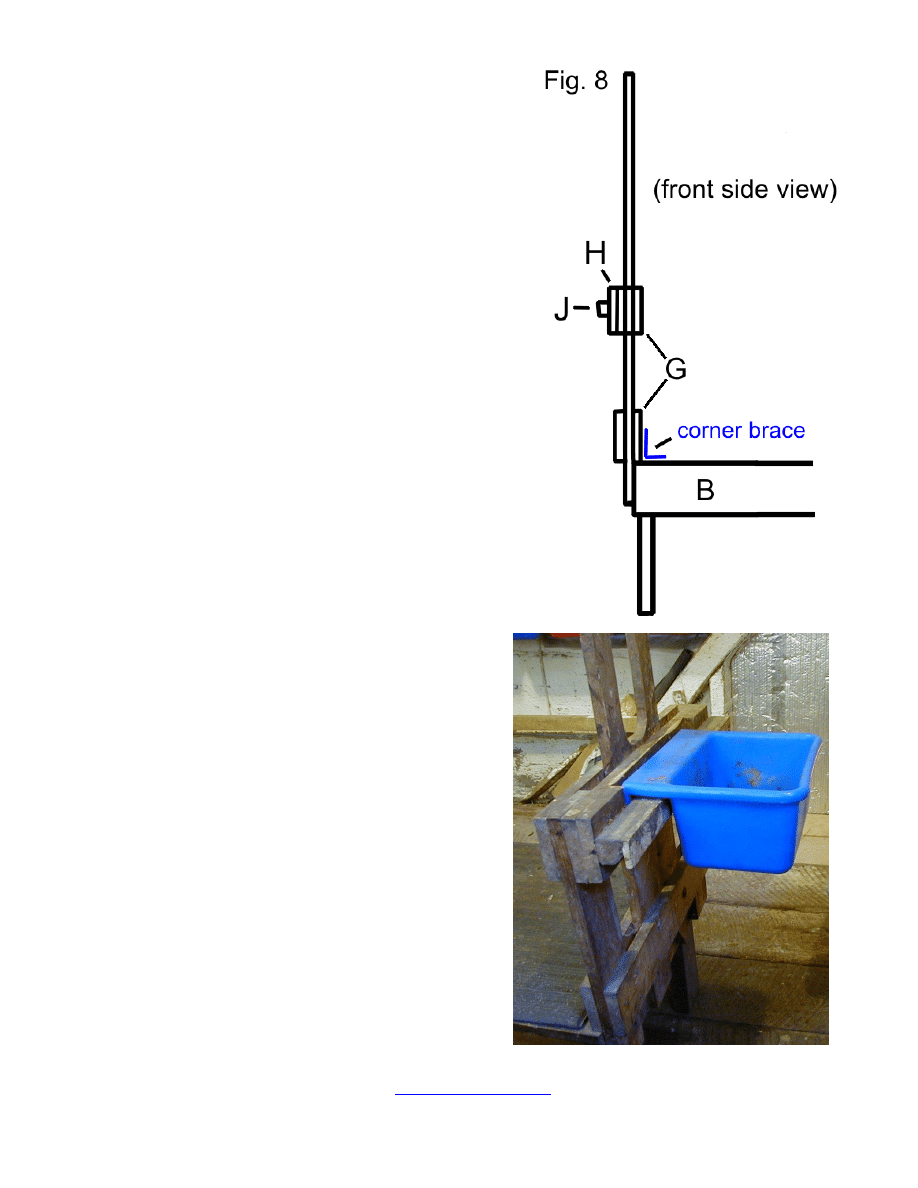
9. Attach parts (J
), 2” x 2” x 20 ½”, to parts
(H) (Fig. 8). Center and attach using two
3” deck screws on each end. This will
hold the removable feeder. See photo
below.
Note: We found that eventually we needed to
add a thin furring strip to (J) so the feeders we
used would fit a little more snuggly. You can
adjust later to suit your needs.
10. Sand all edges and round off corners
Attach Head Gate to Base:
Refer back to Fig. 4. Enlist the aid of a
helper.
1. Hold the head gate with the feeder
holder facing away from the base, so
that the bottom of part (G) rests on the
base surface (A).
2. Attach assembled head gate onto
base using 2” screws though parts
(E1, E2 & F2). DO NOT put screws
through (F1).
Fias Co Farm
www.fiascofarm.com
Copyright© - 2011 Molly Nolte
Page 6 of 6
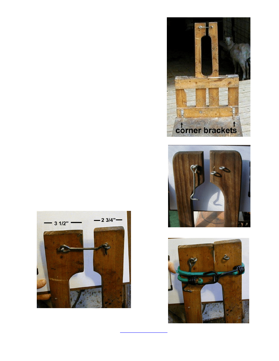
3. Attach the Corner Braces to the head gate
and base by as shown in photo .
Install Head Gate Closure:
Attach
4” hook and eye latch to head gate side
facing toward the base. Normally, the closed
position allows the tops of the head gate (F) to
touch. Additional eyes can be installed for thicker
necked animals (like bucks and wethers). See
photos.
Adjusting to suit your needs:
We removed some of the wood from one (F) piece
so that it would close even tighter to accommodate
younger kids (two months old). In this case, when
using the stand for kids, the gate is secured closed
by wrapping a bungee cord around it.
Wyszukiwarka
Podobne podstrony:
Shelf Television Stand Plans
Stand Display Pedestal Plans
Audyt wewnetrzny (SGHowy) Stand Nieznany (2)
Garret Water Carburator Plans For Water Powered Vehicles
DIY Mortis Dreadmought Plans & Templates
Complete Circuit diagram and plans
arkusz ang stand pr cz2 A
lumber cut off stand
Stand.V.8 kom, Wycena gruntów
Ser Gouda, 1---Eksporty-all, 1---Eksporty---, 4---towary-PL+world, PL-towary-all, 3---milk-products,
bassinet and stand
Jacques Derrida Taking A Stand For Algeria
Ser Edamski, 1---Eksporty-all, 1---Eksporty---, 4---towary-PL+world, PL-towary-all, 3---milk-product
Camel milk czyli co mleko wielbłąda robi dobrego dla mojej skóry
stand
Make Your Resume Stand out From the Pack
ang PR stand cz1 rozw
Milk and Milk Products
więcej podobnych podstron