Front
REMOVAL
1.
REMOVE FRONT
WHEEL
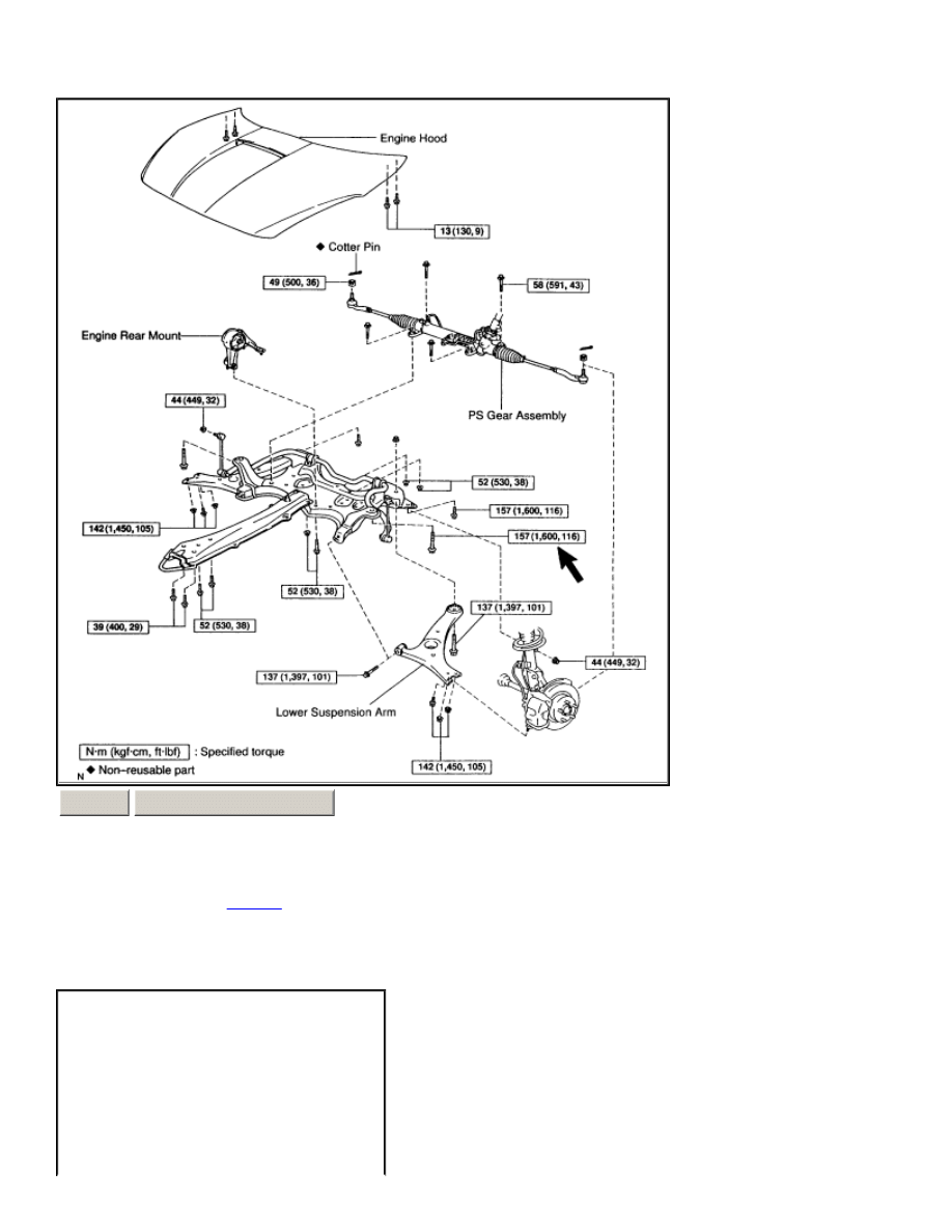
Torque: 103 Nm (1,050 kgf.cm, 76 ft. lbs.)
2.
M/T or A/T RH side: REMOVE LOWER SUSPENSION ARM
a.
Remove the engine under cover.
ZOOM
SIZED FOR PRINT
Page 1 of 5
b.
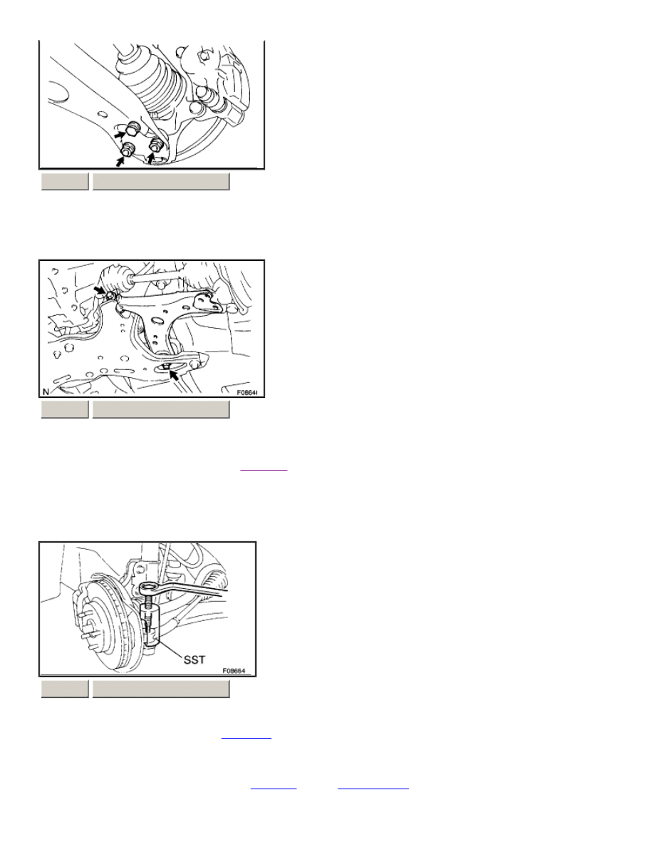
Remove the bolt and 2 nuts, and disconnect the lower suspension arm from the lower ball joint. Torque: 142 Nm (1,450
kgf.cm, 105 ft. lbs.)
c.
Remove the 2 bolts, nut and lower suspension arm. Torque: 137 Nm (1,397 kgf.cm, 101 ft. lbs.) HINT: At the time of
installation, after stabilizing the
suspension
, torque the bolts.
3.
A/T LH side: REMOVE LOWER SUSPENSION ARM
a.
Remove the engine under covers.
b.
Disconnect the RH and LH
tie rod ends
.
1.
Remove the cotter pin and nut. Torque: 49 Nm (500 kgf.cm, 36 ft. lbs.) HINT: At the time of installation, if
the holes for a new cotter pin are not aligned, tighten the nut further up to 60°.
2.
Using SST, disconnect the
tie rod end
from the
steering knuckle
. SST 09610-20012
3.
Employ the same manner described above to the other side.
ZOOM
SIZED FOR PRINT
ZOOM
SIZED FOR PRINT
ZOOM
SIZED FOR PRINT
Page 2 of 5
c.
Disconnect the RH and LH stabilizer bar links.
1.
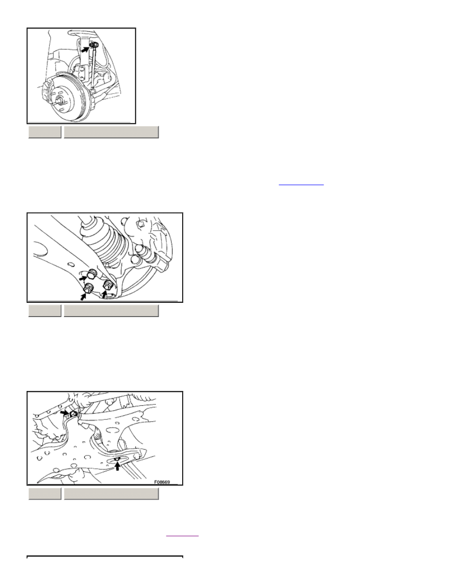
Remove the nut and disconnect the stabilizer bar link from the
shock absorber
. Torque: 44 Nm (449 kgf.cm, 32
ft. lbs.) HINT: If the ball joint turns together with the nut, use a hexagon (5 mm) wrench to hold the stud.
2.
Employ the same manner described above to the other side.
d.
Disconnect the RH and LH lower suspension arms from the lower ball joints.
1.
Remove the bolt and 2 nuts, and disconnect the lower suspension arm from the lower ball joint. Torque: 142
Nm (1,450 kgf.cm, 105 ft. lbs.)
2.
Employ the same manner described above to the other side.
e.
Loosen the lower suspension arm set bolts. Torque: 137 Nm (1,397 kgf.cm, 101 ft. lbs.) HINT: At the time of
installation, after stabilizing the
suspension
, torque the bolts.
f.
Remove the engine hood.
ZOOM
SIZED FOR PRINT
ZOOM
SIZED FOR PRINT
ZOOM
SIZED FOR PRINT
Page 3 of 5
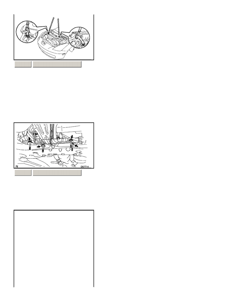
g.
Attach the engine sling device to the engine hangers.
1.
Disconnect the 2 PCV hoses.
2.
Install the No. 1 and No. 2 engine hangers in the correct direction. Parts No.: (1ZZ-FE engine) No. 1 engine
hanger: 12281-22021 No. 2 engine hanger: 12281 -15040 or 12281-15050 Bolt: 91512 -B1016 Parts No. :(2ZZ-
GE engine) No. 1 engine hanger: 12281-88600 No. 2 engine hanger: 12282-88600 Bolt: 91512 -61020 Torque:
38 Nm (387 kgf.cm, 28 ft. lbs.)
3.
Attach the engine chain hoist to the engine hangers. CAUTION: Do not attempt to hang the engine by hooking
the chain to any other part.
h.
Disconnect the PS gear assembly from the suspension member.
1.
Remove the 4 set bolts. Torque: 58 Nm (591 kgf.cm, 43 ft. lbs.)
2.
Tie the PS gear assembly to suspend it securely.
ZOOM
SIZED FOR PRINT
ZOOM
SIZED FOR PRINT
Page 4 of 5
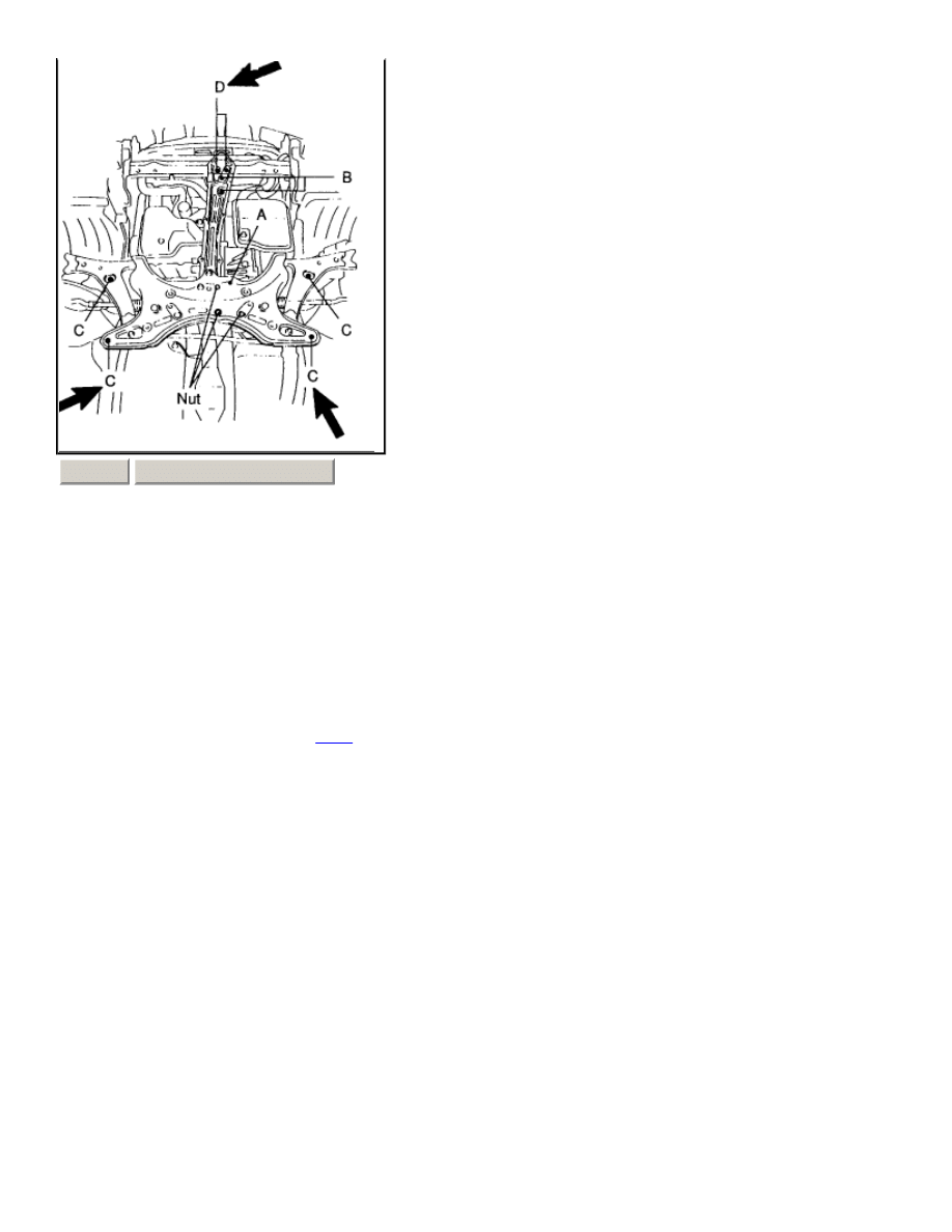
i.
Remove the bolt A and 3 nuts, and disconnect the engine rear mount. Torque: 52 Nm (530 kgf.cm, 38 ft. lbs.) Remove
the 2 bolts (B) and disconnect the engine front mount. Torque: 52 Nm (530 kgf.cm, 38 ft. lbs.)
k.
Using a transmission jack, support the suspension member.
l.
Remove the 6 bolts (C and D) and lower the suspension member. Torque: Bolt C: 157 Nm (1,600 kgf.cm, 116 ft. lbs.) Bolt D:
39 Nm (400 kgf.cm, 29 ft. lbs.)
m.
Remove the 2 bolts, nut and lower suspension arm.
INSTALLATION
Installation is in the reverse order of removal.
HINT: After installation, check the front
wheel
alignment.
ZOOM
SIZED FOR PRINT
Page 5 of 5
Wyszukiwarka
Podobne podstrony:
ARTICLE SUSPENSION LOWER CONTROL ARM REAR SERVICE
ARTICLE SUSPENSION UPPER CONTROL ARM REAR SERVICE
ARTICLE SUSPENSION STABILIZER BAR FRONT SERVICE
ARTICLE SUSPENSION STRUT FRONT REPLACE INSTALL
ARTICLE SUSPENSION STRUT FRONT DISASSEMBLE REASSEMBLE
ARTICLE SUSPENSION STABILIZER BAR REAR SERVICE
ARTICLE SUSPENSION STRUT FRONT REPLACE INSTALL
ARTICLE SUSPENSION STRUT REAR DISASSEMBLE REASSEMBLE
ARTICLE SUSPENSION STRUT REAR REPLACE INSTALL
Implementation of an Active Suspension, Preview Controller for Improved Ride Comfort
więcej podobnych podstron