1F – 152 ENGINE CONTROLS
DAEWOO M-150 BL2
MAA1F180
DIAGNOSTIC TROUBLE CODE (DTC) – P0336 58X CRANKSHAFT POSITION
SENSOR NO PLAUSIBLE SIGNAL
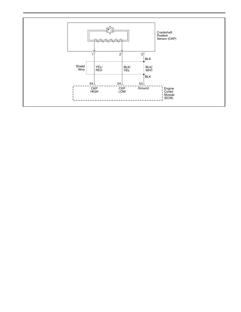
Circuit Description
The 58X reference signal is produced by the crankshaft
position (CKP) sensor. During one crankshaft revolu-
tion, 58 crankshaft pulses will be produced. The engine
control module(ECM) uses the 58X reference signal to
calculate engine rpm and CKP. The ECM constantly
monitors the number of pulses on the 58X reference cir-
cuit and compares them to the number of camshaft posi-
tion (CKP) signal pulses being received. If the ECM
receive and incorrect number of pulses on the 58X refer-
ence circuit, DTC P0336 will set.
Conditions for Setting the DTC
D
This DTC can be stored in “key-on” status.
D
Detected number of teeth is differs by 3 or higher.
Action Taken When the DTC Sets
D
The Malfunction Indicator Lamp (MIL) will illuminate.
D
The ECM will record operating conditions at the time
the diagnostic fails. This information will be stored in
the Freeze Frame and Failure Records buffers.
D
A history DTC is stored.
Conditions for Clearing the MIL/DTC
D
The MIL will turn off after four consecutive ignition
cycles in which the diagnostic runs without a fault.
D
A history DTC will clear after 40 consecutive warm-up
cycles without a fault.
D
DTC(s) can be cleared by using the scan tool.
D
Disconnecting the ECM battery feed for more than 10
seconds.
DIAGNOSTIC AIDS
An intermittent may be caused by a poor connection,
rubbed-through wire insulation or a wire broken inside
the insulation. Check for :
Poor connection – inspect the ECM harness and con-
nectors for improper mating, broken locks, improperly
formed or damaged terminals, and poor terminal-to-wire
connection.
Damaged harness – inspect the wiring harness for dam-
age. If the harness appears to be OK, disconnect the
ECM, turn the ignition ON and observe a voltmeter con-
nected to the 58X reference circuit at the ECM harness
connector while moving the connectors and the wiring
harness related to the ECM. A change in voltage will in-
dicate the location of the fault.
Review the failure records vehicle mileage since the
diagnostic test failed may help determine how often the
condition that caused the DTC to be set occurs. This
may assist in diagnosing the condition.

ENGINE CONTROLS 1F – 153
DAEWOO M-150 BL2
DTC P0336 – 58X Crankshaft Position Sensor No Plausible Signal
Step
Action
Value(s)
Yes
No
1
Perform an Euro On-Board Diagnostic (EOBD)
System Check.
Is the system check complete?
–
Go to Step 2
Go to
“On-Board
Diagnostic
System Check”
2
Attempt to start the engine.
Does the engine start?
–
Go to Step 3
Refer to
“Engine
Cranks But
Will Not Run”
3
1. Review and record Failure Records information.
2. Clear the DTC P0336.
3. Start the engine and idle for 1 minute.
4. Observe the diagnostic trouble codes (DTCs).
Is the DTC P0336 set?
–
Go to Step 4
Go to
“Diagnostic
Aids”
4
1. Disconnect the engine control module(ECM) and
the crankshaft position (CKP) sensor.
2. Check for an open or a low voltage in the CKP
sensor connector and the ECM harness
connector.
Is the problem found?
–
Go to Step 5
Go to Step 6
5
Repair the open or low voltage in the 58X reference
circuit between the CKP sensor connector and the
ECM harness connector.
Is the repair complete?
–
Go to Step 11
–
6
1. Reconnect the ECM and CKP sensor.
2. Connect a digital voltmeter (DVM) to measure
voltage on the 58X reference circuit, terminal 54
at the ECM connector.
3. Observe the voltage while cranking the engine.
Is the voltage near the specified value?
2.5V
Go to Step 9
Go to Step 7
7
Check the connection at the CKP sensor and
replace the terminals if necessary.
Do any terminals require replacement?
–
Go to Step 11
Go to Step 8
8
Replace the CKP sensor.
Is the replacement complete?
–
Go to Step 11
–
9
Check the connections at the ECM and replace the
terminals if necessary.
Do any terminal require replacement?
–
Go to Step 11
Go to Step 10
10
Replace the ECM.
Is the replacement complete?
–
Go to Step 11
–
11
1. Using the scan tool, clear the DTCs.
2. Start the engine and idle at normal operating
temperature.
3. Operate the vehicle within the conditions for
setting this DTC as specified in the supporting
text.
Does the scan tool indicate that this diagnostic run
and passed?
–
Go to Step 12
Go to Step 2
12
Check if any additional DTCs are set.
Are any DTCs displaced that have not been
diagnosed?
–
Go to
Applicable DTC
table
System OK

1F – 154 ENGINE CONTROLS
DAEWOO M-150 BL2
MAA1F180
DIAGNOSTIC TROUBLE CODE (DTC) – P0337 58X CRANKSHAFT POSITION
SENSOR NO SIGNAL
Circuit Description
The 58X reference signal is produced by the crankshaft
position (CKP) sensor. During one crankshaft revolu-
tion, 58 crankshaft pulses will be produced. The engine
control module(ECM) uses the 58X reference signal to
calculate engine rpm and CKP. The ECM constantly
monitors the number of pulses on the 58X reference cir-
cuit and compares them to the number of camshaft posi-
tion (CKP) signal pulses being received. If the ECM
receive and incorrect number of pulses on the 58X refer-
ence circuit, DTC P0337 will set.
Conditions for Setting the DTC
D
This DTC can be stored in “key-on” status.
D
No crankshaft teeth detected.
Action Taken When the DTC Sets
D
The Malfunction Indicator Lamp (MIL) will illuminate.
D
The ECM will record operating conditions at the time
the diagnostic fails. This information will be stored in
the Freeze Frame and Failure Records buffers.
D
A history DTC is stored.
Conditions for Clearing the MIL/DTC
D
The MIL will turn off after four consecutive ignition
cycles in which the diagnostic runs without a fault.
D
A history DTC will clear after 40 consecutive warm-up
cycles without a fault.
D
DTC(s) can be cleared by using the scan tool.
DIAGNOSTIC AIDS
An intermittent may be caused by a poor connection,
rubbed-through wire insulation or a wire broken inside
the insulation. Check for :
Poor connection – inspect the ECM harness and con-
nectors for improper mating, broken locks, improperly
formed or damaged terminals, and poor terminal-to-wire
connection.
Damaged harness – inspect the wiring harness for dam-
age. If the harness appears to be OK, disconnect the
ECM, turn the ignition ON and observe a voltmeter con-
nected to the 58X reference circuit at the ECM harness
connector while moving the connectors and the wiring
harness related to the ECM. A change in voltage will in-
dicate the location of the fault.
Review the failure records vehicle mileage since the
diagnostic test failed may help determine how often the
condition that caused the DTC to be set occurs. This
may assist in diagnosing the condition.

ENGINE CONTROLS 1F – 155
DAEWOO M-150 BL2
DTC P0337 – 58X Crankshaft Position Sensor No Signal
Step
Action
Value(s)
Yes
No
1
Perform an Euro On-Board Diagnostic (EOBD)
System Check.
Is the system check complete?
–
Go to Step 2
Go to
“On-Board
Diagnostic
System Check”
2
Attempt to start the engine.
Does the engine start?
–
Go to Step 3
Refer to
“Engine
Cranks But
Will Not Run”
3
1. Review and record Failure Records information.
2. Clear the DTC P0337.
3. Start the engine and idle for 1 minute.
4. Observe the diagnostic trouble codes (DTCs).
Is the DTC P0337 set?
–
Go to Step 4
Go to
“Diagnostic
Aids”
4
1. Disconnect the engine control module(ECM) and
the crankshaft position (CKP) sensor.
2. Check for an open or a low voltage in the CKP
sensor connector and the ECM harness
connector.
Is the problem found?
–
Go to Step 5
Go to Step 6
5
Repair the open or low voltage in the 58X reference
circuit between the CKP sensor connector and the
ECM harness connector.
Is the repair complete?
–
Go to Step 11
–
6
1. Reconnect the ECM and CKP sensor.
2. Connect a digital voltmeter (DVM) to measure
voltage on the 58X reference circuit, terminal 54
at the ECM connector.
3. Observe the voltage while cranking the engine.
Is the voltage near the specified value?
2.5V
Go to Step 9
Go to Step 7
7
Check the connection at the CKP sensor and
replace the terminals if necessary.
Do any terminals require replacement?
–
Go to Step 11
Go to Step 8
8
Replace the CKP sensor.
Is the replacement complete?
–
Go to Step 11
–
9
Check the connections at the ECM and replace the
terminals if necessary.
Do any terminal require replacement?
–
Go to Step 11
Go to Step 10
10
Replace the ECM.
Is the replacement complete?
–
Go to Step 11
–
11
1. Using the scan tool, clear the DTCs.
2. Start the engine and idle at normal operating
temperature.
3. Operate the vehicle within the conditions for
setting this DTC as specified in the supporting
text.
Does the scan tool indicate that this diagnostic run
and passed?
–
Go to Step 12
Go to Step 2
12
Check if any additional DTCs are set.
Are any DTCs displaced that have not been
diagnosed?
–
Go to
Applicable DTC
table
System OK
1F – 156 ENGINE CONTROLS
DAEWOO M-150 BL2
MAA1F190
DIAGNOSTIC TROUBLE CODE (DTC) – P0341 CAMSHAFT POSITION SENSOR
RATIONALITY
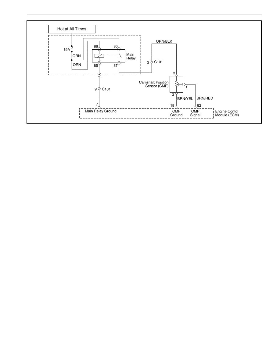
Circuit Description
The Camshaft Position Sensor is used to detect Cam-
shaft position and to have correlation with Crankshaft
position so that the ECM can determine which cylinder is
ready to be fueled by the injector. The polarity of cam-
shaft sensor signal must be changed only once per
crankshaft position.
Conditions for Setting the DTC
D
Engine is running.
D
No traction of CMP signal between teeth 18 and 82
but change in polarity.
Action Taken When the DTC Sets
D
The Malfunction Indicator Lamp (MIL) will illuminate.
D
The ECM will record operating conditions at the time
the diagnostic fails. This information will be stored in
the Freeze Frame and Failure Records buffers.
D
A history DTC is stored.
Conditions for Clearing the MIL/DTC
D
The MIL will turn off after four consecutive ignition
cycles in which the diagnostic runs without a fault.
D
A history DTC will clear after 40 consecutive warm-up
cycles without a fault.
D
DTC(s) can be cleared by using the scan tool.
Diagnostic Aids
Check and correct any abnormal engine noise before
using the diagnostic table.
Any circuitry that is suspected as causing engine noise
complaint should be thoroughly checked for the follow-
ing conditions :
D
Backed-out terminals.
D
Improper mating.
D
Broken locks.
D
Improperly formed.
D
Damaged terminals.
D
Poor terminal-to-wire connections.
D
Physical damage to the wiring harness.

ENGINE CONTROLS 1F – 157
DAEWOO M-150 BL2
DTC P0341 – Camshaft Position Sensor Rationality
Step
Action
Value(s)
Yes
No
1
Perform an Euro On-Board Diagnostic (EOBD)
System Check.
Is the system check complete?
–
Go to Step 2
Go to
“On-Board
Diagnostic
System Check”
2
1. Turn the ignition switch to LOCK.
2. Disconnect the CMP sensor connector.
3. Check for a faulty connector or terminals.
Is the problem found?
–
Go to Step 4
Go to Step 3
3
1. Turn the ignition switch to ON.
2. Disconnect the ECM connector.
3. Inspect the ECM pins and connector for bent or
damaged terminals.
4. Check the wire between the CMP sensor terminal
1 and ECM connector 82 for an open or short to
ground or short to battery voltage while related
connectors and wiring harness.
5. Check the wires between the CMP sensor
terminal 2 and ECM connector 18 for an open
while moving related connectors and wiring
harness.
Is the problem found?
–
Go to Step 4
Go to Step 5
4
1. Turn the ignition switch to LOCK.
2. Repair or replace the wire or the connector.
3. Clear any DTCs from the ECM.
4. Run the engine.
5. Perform the diagnostic system check.
Is the repair complete?
–
System OK
–
5
1. Turn the ignition switch to LOCK.
2. Replace the CMP sensor.
3. Clear any DTCs from the ECM.
4. Run the engine.
5. Perform the diagnostic system check.
Does DTC P0341 reset?
–
System OK
Go to Step 6
6
1. Replace the ECM.
2. Run the engine.
3. Perform the Diagnostic system check.
Is the replacement complete?
–
Go to Step 7
–
7
1. Using the scan tool, clear the DTCs.
2. Start the engine and idle at normal operating
temperature.
3. Operate the vehicle within the conditions for
setting this DTC as specified in the supporting
text.
Does the scan tool indicate that this diagnostic run
and passed?
–
Go to Step 8
–
8
Check if any additional DTCs are set.
Are any DTCs displayed that have not been
diagnosed?
–
Go to
Applicable DTC
table
System OK

1F – 158 ENGINE CONTROLS
DAEWOO M-150 BL2
MAA1F190
DIAGNOSTIC TROUBLE CODE (DTC) – P0342 CAMSHAFT POSITION SENSOR
NO SIGNAL
Circuit Description
The Camshaft Position Sensor is used to detect Cam-
shaft position and to have correlation with Crankshaft
position so that the ECM can determine which cylinder is
ready to be fueled by the injector. The polarity of cam-
shaft sensor signal must be changed only once per
crankshaft position.
Conditions for Setting the DTC
D
Engine is running.
D
No traction of CMP signal between teeth 18 and 82
but change in polarity.
Action Taken When the DTC Sets
D
The Malfunction Indicator Lamp (MIL) will illuminate.
D
The ECM will record operating conditions at the time
the diagnostic fails. This information will be stored in
the Freeze Frame and Failure Records buffers.
D
A history DTC is stored.
Conditions for Clearing the MIL/DTC
D
The MIL will turn off after four consecutive ignition
cycles in which the diagnostic runs without a fault.
D
A history DTC will clear after 40 consecutive warm-up
cycles without a fault.
D
DTC(s) can be cleared by using the scan tool.
DIAGNOSTIC AIDS
Check and correct any abnormal engine noise before
using the diagnostic table.
Any circuitry that is suspected as causing engine noise
complaint should be thoroughly checked for the follow-
ing conditions :
D
Backed-out terminals.
D
Improper mating.
D
Broken locks.
D
Improperly formed.
D
Damaged terminals.
D
Poor terminal-to-wire connections.
D
Physical damage to the wiring harness.

ENGINE CONTROLS 1F – 159
DAEWOO M-150 BL2
DTC P0342 – Camshaft Position Sensor No Signal
Step
Action
Value(s)
Yes
No
1
Perform an Euro On-Board Diagnostic (EOBD)
System Check.
Is the system check complete?
–
Go to Step 2
Go to
“On-Board
Diagnostic
System Check”
2
1. Turn the ignition switch to LOCK.
2. Disconnect the CMP sensor connector.
3. Check for a faulty connector or termin1als.
Is the problem found?
–
Go to Step 4
Go to Step 3
3
1. Turn the Turn the ignition switch to ON.
2. Disconnect the ECM connector.
3. Inspect the ECM pins and connector for bent or
damaged terminals.
4. Check the wire between the CMP sensor terminal
1 and ECM connector 82 for an open or short to
ground or short to battery voltage while related
connectors and wiring harness.
5. Check the wires between the CMP sensor
terminal 2 and ECM connector 18 for an open
while moving related connectors and wiring
harness.
Is the problem found?
–
Go to Step 4
Go to Step 5
4
1. Turn the ignition switch to LOCK.
2. Repair or replace the wire or the connector.
3. Clear any DTCs from the ECM.
4. Run the engine.
5. Perform the diagnostic system check.
Is the repair complete?
–
System OK
–
5
1. Turn the ignition switch to LOCK.
2. Replace the CMP sensor.
3. Clear any DTCs from the ECM.
4. Run the engine.
5. Perform the diagnostic system check.
Does DTC P0342 reset?
–
System OK
Go to Step 6
6
1. Replace the ECM.
2. Run the engine.
3. Perform the Diagnostic system check.
Is the replacement complete?
–
Go to Step 7
–
7
1. Using the scan tool, clear the DTCs.
2. Start the engine and idle at normal operating
temperature.
3. Operate the vehicle within the conditions for
setting this DTC as specified in the supporting
text.
Does the scan tool indicate that this diagnostic run
and passed?
–
Go to Step 8
–
8
Check if any additional DTCs are set.
Are any DTCs displayed that have not been
diagnosed?
–
Go to
Applicable DTC
table
System OK

1F – 160 ENGINE CONTROLS
DAEWOO M-150 BL2
MAA1F200
DIAGNOSTIC TROUBLE CODE (DTC) – P0351 IGNITION SIGNAL COIL A FAULT
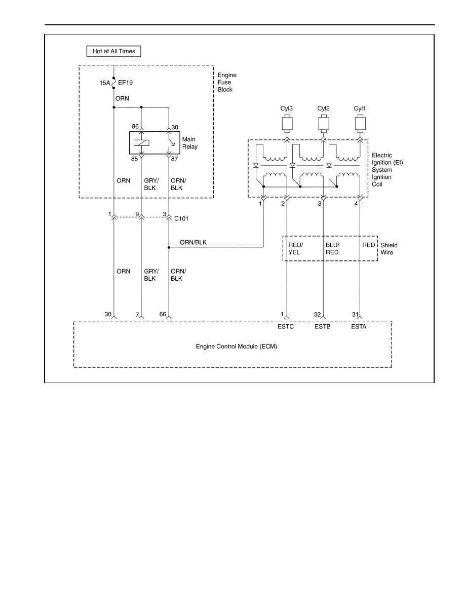
Circuit Description
The engine control module (ECM) provides a ground for
the electronic spark timing 1 circuit. When the ECM re-
moves the ground path of the ignition primary coil, the
magnetic field produced by the coil collapses. The col-
lapsing magnetic field produces a voltage in the secon-
dary coil which fires the spark plug. The circuit between
the ECM and the electronic ignition system is monitored
for an open circuit, short to voltage, and low voltage.
When the ECM detects a problem in the spark timing 1
circuit, it will set DTC P0351.
Conditions for Setting the DTC
D
This DTC can be stored in “key-on” status.
D
Time of fault fall occurrence is greater than time of the
DIS fall occurrence.
D
Must receive more than 40 failure within 80 test
cycles.
Action Taken When the DTC Sets
D
The Malfunction Indicator Lamp (MIL) will illuminate.
D
The ECM will record operating conditions at the time
the diagnostic fails. This information will be stored in
the Freeze Frame and Failure Records buffers.
D
A history DTC is stored.
Conditions for Clearing the MIL/DTC
D
The MIL will turn off after four consecutive ignition
cycles in which the diagnostic runs without a fault.
D
A history DTC will clear after 40 consecutive warm-up
cycles without a fault.

ENGINE CONTROLS 1F – 161
DAEWOO M-150 BL2
D
DTC(s) can be cleared by using the scan tool.
D
Disconnecting the ECM battery feed for more than 10
seconds.
DIAGNOSTIC AIDS
Check and correct any abnormal engine noise before
using the diagnostic table.
Any circuitry that is suspected as causing engine noise
complaint should be thoroughly checked for the follow-
ing conditions :
D
Backed-out terminals.
D
Improper mating.
D
Broken locks.
D
Improperly formed.
D
Damaged terminals.
D
Poor terminal-to-wire connections.
D
Physical damage to the wiring harness.
DTC P0351 – Ignition Signal Coil A Fault
Step
Action
Value(s)
Yes
No
1
Perform an Euro On-Board Diagnostic (EOBD)
System Check.
Is the system check complete?
–
Go to Step 2
Go to
“On-Board
Diagnostic
System Check”
2
Check for a faulty connection or a damaged terminal
1 at the ignition coil.
Is a problem found?
–
Go to Step 8
Go to Step 3
3
Check for a faulty connection or a damaged terminal
31 at the engine control module(ECM) connector.
Is the problem found?
–
Go to Step 8
Go to Step 4
4
1. Turn the ignition switch to LOCK.
2. Disconnect the ECM.
3. Check the ignition control circuit for a short to
ground.
Is the problem found?
–
Go to Step 8
Go to Step 5
5
Check the ignition control circuit for a short to
battery voltage.
Is the problem found?
–
Go to Step 8
Go to Step 6
6
Check for an open in the ignition control.
Is the problem found?
–
Go to Step 8
Go to Step 7
7
Replace the ECM.
Is the replacement complete?
–
Go to Step 8
–
8
1. Using the scan tool, clear the Diagnostic Trouble
Codes(DTCs).
D
Start the engine and Idle at normal operating
temperature.
D
Operate the vehicle within the conditions for
setting this DTC as specified in the supporting
text.
Does the scan tool indicate that this diagnostic ran
and passed?
–
Go to Step 9
–
9
Check if any additional DTCs are set.
Are any DTCs displayed that have not been
diagnosed?
–
Go to
Applicable DTC
table
System OK

1F – 162 ENGINE CONTROLS
DAEWOO M-150 BL2
MAA1F200
DIAGNOSTIC TROUBLE CODE (DTC) – P0352 IGNITION SIGNAL COIL B FAULT
Circuit Description
The engine control module (ECM) provides a ground for
the electronic spark timing 3 circuit. When the ECM re-
moves the ground path of the ignition primary coil, the
magnetic field produced by the coil collapses. The col-
lapsing magnetic field produces a voltage in the secon-
dary coil, which fires the spark plug. The circuit between
the ECM and the electronic ignition system is monitored
for an open circuit, short to voltage, and low voltage.
When the ECM detects a problem in the spark timing 3
circuit, it will set DTC P0352.
Conditions for Setting the DTC
D
This DTC can be stored in “key-on” status.
D
Time of fault fall occurrence is greater than time of the
DIS fall occurrence.
D
Must receive more than 40 failure within 80 test
cycles.
Action Taken When The DTCs Sets
D
The Malfunction Indicator Lamp (MIL) will illuminate.
D
The ECM will record operating conditions at the time
the diagnostic fails. This information will be stored in
the Freeze Frame and failure records buffers.
D
A history DTC is stored.
D
The ECM will default to 6 degree timing.
Conditions for Clearing the MIL/DTC
D
The MIL will turn off after four consecutive ignition
cycles in which the diagnostic runs without a fault.

ENGINE CONTROLS 1F – 163
DAEWOO M-150 BL2
D
A history DTC will clear after 40 consecutive warm up
cycles without a fault.
D
Using the scan tool can clear DTC(s).
D
Disconnecting the ECM battery feed for 10 seconds.
DIAGNOSTIC AIDS
Check and correct any abnormal engine noise before
using the diagnostic table.
Any circuitry that is suspected as causing engine noise
complaint should be thoroughly checked for the follow-
ing conditions :
D
Backed-out terminals.
D
Improper mating.
D
Broken locks.
D
Improperly formed.
D
Damaged terminals.
D
Poor terminal-to-wire connections.
D
Physical damage to the wiring harness.
DTC P0352 – Ignition Signal Coil B Fault
Step
Action
Value(s)
Yes
No
1
Perform an Euro On-Board Diagnostic (EOBD)
System Check.
Is the system check complete?
–
Go to Step 2
Go to
“On-Board
Diagnostic
System Check”
2
Check for a faulty connection or a damaged terminal
3 at the ignition coil.
Is a problem found?
–
Go to Step 8
Go to Step 3
3
Check for a faulty connection or a damaged terminal
32 at the engine control module(ECM) connector.
Is the problem found?
–
Go to Step 8
Go to Step 4
4
1. Turn the ignition switch to LOCK.
2. Disconnect the ECM.
3. Check the ignition control circuit for a short to
ground
Is the problem found?
–
Go to Step 8
Go to Step 5
5
Check the ignition control circuit for a short to
battery voltage.
Is the problem found?
–
Go to Step 8
Go to Step 6
6
Check for an open in the ignition control.
Is the problem found?
–
Go to Step 8
Go to Step 7
7
Replace the ECM.
Is the replacement complete?
–
Go to Step 8
–
8
1. Using the scan tool, clear the Diagnostic Trouble
Codes(DTCs).
D
Start the engine and Idle at normal operating
temperature.
D
Operate the vehicle within the conditions for
setting this DTC as specified in the supporting
text.
Does the scan tool indicate that this diagnostic ran
and passed?
–
Go to Step 9
–
9
Check if any additional DTCs are set.
Are any DTCs displayed that have not been
diagnosed?
–
Go to
Applicable DTC
table
System OK
1F – 164 ENGINE CONTROLS
DAEWOO M-150 BL2
MAA1F200
DIAGNOSTIC TROUBLE CODE (DTC) – P0353 IGNITION SIGNAL COIL C FAULT
Circuit Description
The engine control module (ECM) provides a ground for
the electronic spark timing 3 circuit. When the ECM re-
moves the ground path of the ignition primary coil, the
magnetic field produced by the coil collapses. The col-
lapsing magnetic field produces a voltage in the secon-
dary coil, which fires the spark plug. The circuit between
the ECM and the electronic ignition system is monitored
for an open circuit, short to voltage, and low voltage.
When the ECM detects a problem in the spark timing 3
circuit, it will set DTC P0352.
Conditions for Setting the DTC
D
This DTC can be stored in “key-on” status.
D
Time of fault fall occurrence is greater than time of the
DIS fall occurrence.
D
Must receive more than 40 failure within 80 test
cycles.
Action Taken When The DTCs Sets
D
The Malfunction Indicator Lamp (MIL) will illuminate.
D
The ECM will record operating conditions at the time
the diagnostic fails. This information will be stored in
the Freeze Frame and failure records buffers.
D
A history DTC is stored.
D
The ECM will default to 6 degree timing.
Conditions for Clearing the MIL/DTC
D
The MIL will turn off after four consecutive ignition
cycles in which the diagnostic runs without a fault.

ENGINE CONTROLS 1F – 165
DAEWOO M-150 BL2
D
A history DTC will clear after 40 consecutive warm up
cycles without a fault.
D
Using the scan tool can clear DTC(s).
D
Disconnecting the ECM battery feed for 10 seconds.
DIAGNOSTIC AIDS
Check and correct any abnormal engine noise before
using the diagnostic table.
Any circuitry that is suspected as causing engine noise
complaint should be thoroughly checked for the follow-
ing conditions :
D
Backed-out terminals.
D
Improper mating.
D
Broken locks.
D
Improperly formed.
D
Damaged terminals.
D
Poor terminal-to-wire connections.
D
Physical damage to the wiring harness.
DTC P0353 – Ignition Signal Coil C Fault
Step
Action
Value(s)
Yes
No
1
Perform an Euro On-Board Diagnostic (EOBD)
System Check.
Is the system check complete?
–
Go to Step 2
Go to
“On-Board
Diagnostic
System Check”
2
Check for a faulty connection or a damaged terminal
3 at the ignition coil.
Is a problem found?
–
Go to Step 8
Go to Step 3
3
Check for a faulty connection or a damaged terminal
32 at the engine control module(ECM) connector.
Is the problem found?
–
Go to Step 8
Go to Step 4
4
1. Turn the ignition switch to LOCK.
2. Disconnect the ECM.
3. Check the ignition control circuit for a short to
ground
Is the problem found?
–
Go to Step 8
Go to Step 5
5
Check the ignition control circuit for a short to
battery voltage.
Is the problem found?
–
Go to Step 8
Go to Step 6
6
Check for an open in the ignition control.
Is the problem found?
–
Go to Step 8
Go to Step 7
7
Replace the ECM.
Is the replacement complete?
–
Go to Step 8
–
8
1. Using the scan tool, clear the Diagnostic Trouble
Codes(DTCs).
D
Start the engine and Idle at normal operating
temperature.
D
Operate the vehicle within the conditions for
setting this DTC as specified in the supporting
text.
Does the scan tool indicate that this diagnostic ran
and passed?
–
Go to Step 9
–
9
Check if any additional DTCs are set.
Are any DTCs displayed that have not been
diagnosed?
–
Go to
Applicable DTC
table
System OK
1F – 166 ENGINE CONTROLS
DAEWOO M-150 BL2
MAA1F210
DIAGNOSTIC TROUBLE CODE (DTC) – P1382 ROUGH ROAD DATA INVALID
(NON ABS)
Circuit Description
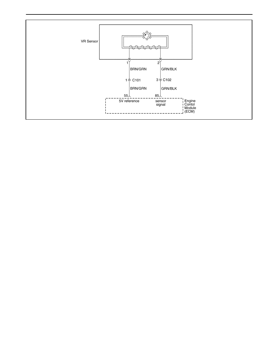
The VR sensor is used to detecting the road situation.
By sensing difference of wheel rotation duration caused
by bumps or potholes in the road, the Engine Control
Module (ECM) can determine if the changes in crank-
shaft speed are due to engine misfire or are driveline in-
duced. If the VR sensor detects a rough road condition,
the ECM misfire detection diagnostic will be de-acti-
vated.
The VR sensor is located in front–right wheel.
Conditions for Setting the DTC
D
Vehicle speed is higher than 10km/h(6.21mph).
D
No Vehicle Speed Sensor error not set.
D
VR sensor output signal is higher than 0.26.
D
VR sensor output signal is not change for 30seconds.
Action Taken When The DTCs Sets
D
The Malfunction Indicator Lamp (MIL) will not illumi-
nate.
D
The ECM will store conditions which were present
when the DTC was set as Failure Records data only.
D
This information will not be stored in the Freeze
Frame data.
Conditions for Clearing the MIL/DTC
D
A history DTC will clear after 40 consecutive warm-up
cycles without a fault.
D
DTC(s) can be cleared by using the scan tool.
D
Disconnecting the ECM battery feed for more than 10
seconds.

ENGINE CONTROLS 1F – 167
DAEWOO M-150 BL2
DTC P1382 – Rough Road Data Invalid (NON ABS)
Step
Action
Value(s)
Yes
No
1
Perform an Euro On-Board Diagnostic (EOBD)
System Check.
Was the check performed?
–
Go to Step 2
Go to
“On-Board
Diagnostic
System Check”
2
1. Turn the ignition ON, with engine OFF.
2. Install a scan tool to the Data Link Connector
(DLC).
3. Review and record the scan tool Failure Records
data.
4. Operate the vehicle within Failure Records
conditions as noted.
5. Using the scan tool, monitor specific Diagnostic
Trouble Code (DTC) info for DTC P1382.
Does the scan tool indicate that DTC P1382 failed?
–
Go to Step 4
Go to Step 3
3
1. Check for the following conditions and repair as
needed:
2. VR sensor seal missing or damaged.
3. VR sensor mounting flanges cracked, missing, or
incorrectly installed.
Is the repair complete?
–
Go to Step 14
Go to
“Diagnostic
Aids”
4
1. Turn the ignition OFF.
2. Disconnect the VR sensor electrical connector.
3. Turn the ignition ON, with the engine OFF.
4. Observe the VR sensor value displayed on the
scan tool.
Is the VR sensor value near the specified value?
0V
Go to Step 5
Go to Step 12
5
1. Jumper the 5 volt reference circuit, terminal 1 and
the VR sensor signal circuit, terminal 2 together at
the VR sensor harness connector.
2. Observe the VR sensor value displayed on the
scan tool.
Is the VR sensor value near the specified value?
4.95V
Go to Step 6
Go to Step 7
6
1. Turn the ignition OFF.
2. Disconnect the Engine Control Module (ECM) and
check the sensor ground circuit for high
resistance, an open between the ECM and the
wheel speed sensor, or for a poor connection at
the terminal 85 of the ECM and repair as needed.
Is the repair complete?
–
Go to Step 14
Go to Step 10
7
Check the 5 volt reference circuit for high resistance,
an open between the ECM and the VR sensor, or a
poor connection at the terminal 55 of the ECM and
repair as needed.
Is the repair complete?
–
Go to Step 14
Go to Step 8
8
1 Turn the ignition OFF.
2. Disconnect the ECM and check the VR sensor
signal circuit for high resistance, an open, a low
voltage, or a short to the sensor ground circuit
and repair as needed.
Is the repair complete?
–
Go to Step 14
Go to Step 9

1F – 168 ENGINE CONTROLS
DAEWOO M-150 BL2
DTC P1382 – Rough Road Data Invalid (NON ABS) (Cont’d)
Step
Action
Value(s)
Yes
No
9
Check the VR sensor signal circuit for a poor
connection at the ECM and repair as needed.
Is the repair complete?
–
Go to Step 14
Go to Step 13
10
Check for a poor connection at terminal 2 of the VR
sensor and repair as needed.
Is the repair complete?
–
Go to Step 14
Go to Step 11
11
Replace the VR sensor.
Is the repair complete?
–
Go to Step 14
–
12
1. Turn the ignition OFF.
2. Disconnect the ECM.
3. Turn the ignition ON.
4. Check the VR sensor signal circuit for a short to
battery voltage or a short to the 5 volt reference
circuit and repair as needed.
Is the repair complete?
–
Go to Step 14
Go to Step 13
13
1. Turn the ignition OFF.
2. Replace the ECM.
Is the repair complete?
–
Go to Step 14
–
14
1. Using the scan tool, clear the DTCs.
2. Start the engine and idle at normal operating
temperature.
3. Operate the vehicle within the conditions for
setting this DTC as specified in the supporting
text.
Does the scan tool indicate that this diagnostic ran
and passed?
–
Go to Step 15
Go to Step 2
15
Check if any additional DTCs are set.
Are any DTCs displayed that have not been
diagnosed?
–
Go to
Applicable DTC
table
System OK

ENGINE CONTROLS 1F – 169
DAEWOO M-150 BL2
BLANK

1F – 170 ENGINE CONTROLS
DAEWOO M-150 BL2
MAA1F220
DIAGNOSTIC TROUBLE CODE (DTC) – P1382 ROUGH ROAD DATA INVALID
(ABS)
Circuit Description
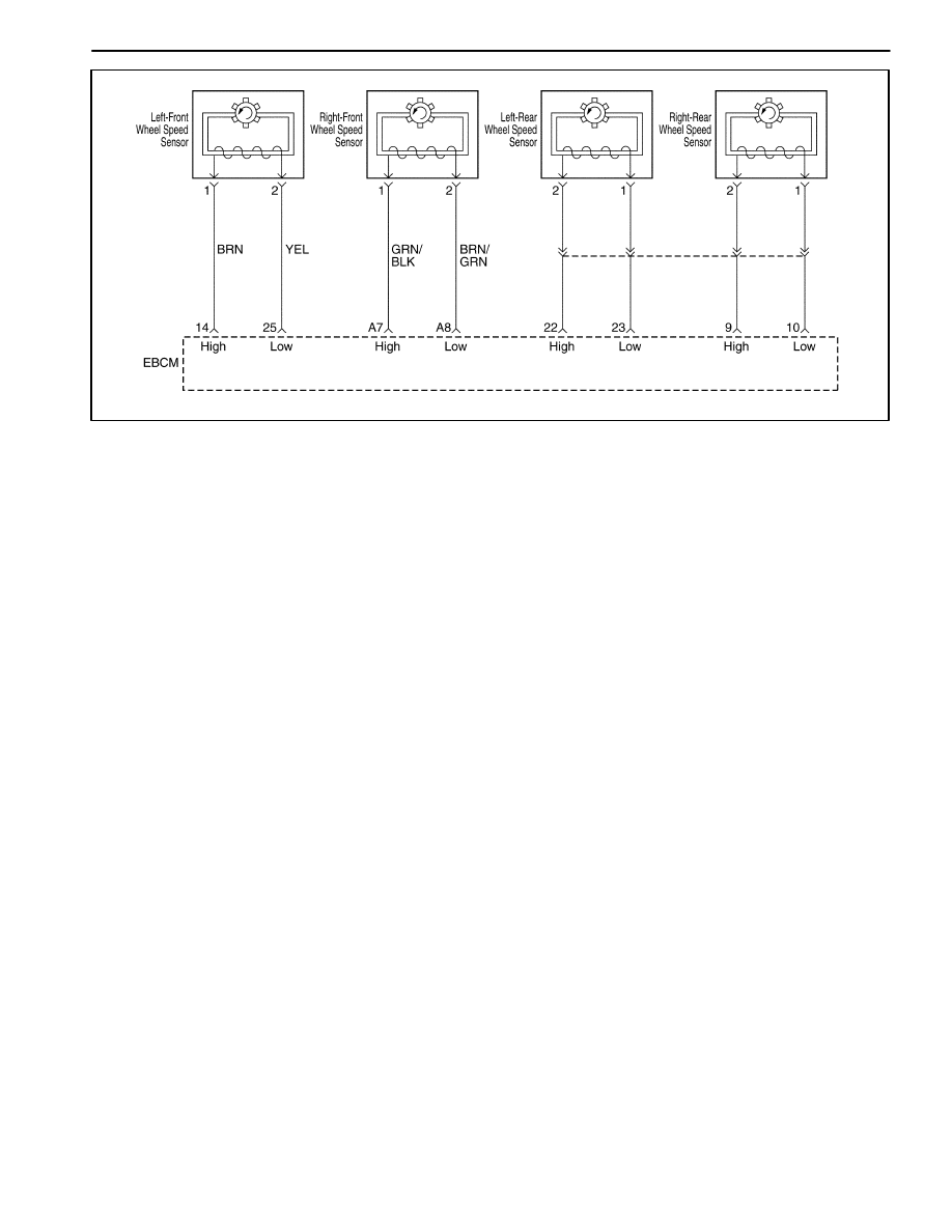
The wheel speed sensor is used to detecting the road
situation.
As the wheel is rotated, the wheel speed sensor pro-
duces an AC voltage that increase with wheel speed.
The EBCM uses the frequency of the AC signal to calcu-
late wheel speed. The wheel speed sensor is connected
to EBCM by a “twisted pair” of wires. Twisting reduces
noise susceptibility than may cause a DTC to se.If the
wheel speed sensor detects a rough road condition, the
ECM misfire detection diagnostic will be de-activated.
Conditions for Setting the DTC
D
Vehicle speed is higher than 10km/h(6.21mph).
D
No Vehicle Speed Sensor error not set.
D
VR sensor output signal is higher than 0.26.
D
VR sensor output signal is not change for 30seconds.
Action Taken When the DTC Sets
D
The Malfunction Indicator Lamp (MIL) will not illumi-
nate.
D
The ECM will store conditions which were present
when the DTC was set as Failure Records data only.
D
This information will not be stored in the Freeze
Frame data.
Conditions for Clearing the MIL/DTC
D
A history DTC will clear after 40 consecutive warm-up
cycles without a fault.
D
DTC(s) can be cleared by using the scan tool.
D
Disconnecting the ECM battery feed for more than 10
seconds.

ENGINE CONTROLS 1F – 171
DAEWOO M-150 BL2
DTC P1382 – Rough Road Data Invalid (ABS)
Step
Action
Value(s)
Yes
No
1
Perform an Euro On-Board Diagnostic (EOBD)
System Check.
Was the check performed?
–
Go to Step 2
Go to
“On-Board
Diagnostic
System Check”
2
1. Turn the ignition On, with engine OFF.
2. Install a scan tool to the Data Link Connector
(DLC).
3. Review and record the scan tool Failure Records
data.
4. Operate the vehicle within Failure Records
conditions as noted.
5. Using the scan tool, monitor specific Diagnostic
Trouble Code (DTC) info for DTC P1382.
Does the scan tool indicate that DTC P1382 failed?
–
Go to Step 4
Go to Step 3
3
1. Check for the following conditions and repair as
needed:
2. Wheel speed sensor seal missing or damaged.
3. Wheel speed sensor mounting flanges cracked,
missing, or incorrectly installed.
Is the repair complete?
–
Go to Step 14
Go to
“Diagnostic
Aids”
4
1. Turn the ignition OFF.
2. Disconnect the defected Wheel speed sensor
electrical connector.
3. Turn the ignition ON, with the engine OFF.
4. Observe the wheel speed sensor value displayed
on the scan tool.
Is the Wheel speed sensor value near the specified
value?
0V
Go to Step 5
Go to Step 12
5
1. Jumper the 5 volt reference circuit, the Wheel
speed sensor signal circuit, together at the
defected wheel speed sensor harness connector.
2. Observe the defected Wheel speed sensor value
displayed on the scan tool.
Is the wheel speed sensor value near the specified
value?
4.95V
Go to Step 6
Go to Step 7
6
1. Turn the ignition OFF.
2. Disconnect the Engine Control Module (ECM) and
check the sensor ground circuit for high
resistance, an open between the ECM and the
Wheel speed sensor, or for a poor connection of
the ECM and repair as needed.
Is the repair complete?
–
Go to Step 14
Go to Step 10
7
Check the 5 volt reference circuit for high resistance,
an open between the ECM and the wheel speed
sensor, or a poor connection of the ECM and repair
as needed.
Is the repair complete?
–
Go to Step 14
Go to Step 8
8
1. Turn the ignition OFF.
2. Disconnect the ECM and check the wheel speed
sensor signal circuit for high resistance, an open,
a low voltage, or a short to the sensor ground
circuit and repair as needed.
Is the repair complete?
–
Go to Step 14
Go to Step 9

1F – 172 ENGINE CONTROLS
DAEWOO M-150 BL2
DTC P1382 – Rough Road Data Invalid (ABS) (Cont’d)
Step
Action
Value(s)
Yes
No
9
Check the wheel speed sensor signal circuit for a
poor connection at the ECM and repair as needed.
Is the repair complete?
–
Go to Step 14
Go to Step 13
10
Check for a poor connection at terminal 3 of the
wheel speed sensor and repair as needed.
Is the repair complete?
–
Go to Step 14
Go to Step 11
11
Replace the wheel speed sensor.
Is the repair complete?
–
Go to Step 14
–
12
1. Turn the ignition OFF.
2. Disconnect the ECM.
3. Turn the ignition ON.
4. Check the wheel speed sensor signal circuit for a
short to voltage or a short to the 5 volt reference
circuit and repair as needed.
Is the repair complete?
–
Go to Step 14
Go to Step 13
13
1. Turn the ignition OFF.
2. Replace the ECM.
Is the repair complete?
–
Go to Step 14
–
14
1. Using the scan tool, clear the DTCs.
2. Start the engine and idle at normal operating
temperature.
3. Operate the vehicle within the conditions for
setting this DTC as specified in the supporting
text.
Does the scan tool indicate that this diagnostic ran
and passed?
–
Go to Step 15
Go to Step 2
15
Check if any additional DTCs are set.
Are any DTCs displayed that have not been
diagnosed?
–
Go to
Applicable DTC
table
System OK

ENGINE CONTROLS 1F – 173
DAEWOO M-150 BL2
BLANK

1F – 174 ENGINE CONTROLS
DAEWOO M-150 BL2
MAA1F210
DIAGNOSTIC TROUBLE CODE (DTC) – P1385 ROUGH ROAD SENSOR CIRCUIT
FAULT (NON ABS)
Circuit Description
The VR sensor is used to detecting the road situation.
By sensing difference of wheel rotation duration caused
by bumps or potholes in the road, the Engine Control
Module (ECM) can determine if the changes in crank-
shaft speed are due to engine misfire or are driveline in-
duced. If the VR sensor detects a rough road condition,
the ECM misfire detection diagnostic will be de-acti-
vated.
Conditions for Setting the DTC
D
Vehicle speed is higher than 10km/h(6.21mph).
D
No Vehicle Speed Sensor error not set.
D
VR sensor output signal is higher than 0.26.
D
VR sensor output signal is not change for 30 sec-
onds.
Action Taken When The DTCs Sets
D
The Malfunction Indicator Lamp (MIL) will not illumi-
nate.
D
The ECM will store conditions which were present
when the DTC was set as Failure Records data only.
D
This information will not be stored in the Freeze
Frame data.
Conditions for Clearing the MIL/DTC
D
A history DTC will clear after 40 consecutive warm-up
cycles without a fault.
D
DTC(s) can be cleared by using the scan tool.
D
Disconnecting the ECM battery feed for more than 10
seconds.

ENGINE CONTROLS 1F – 175
DAEWOO M-150 BL2
DTC P1385 – Rough Road Sensor Circuit Fault (NON ABS)
Step
Action
Value(s)
Yes
No
1
Perform an Euro On-Board Diagnostic (EOBD)
System Check.
Was the check performed?
–
Go to Step 2
Go to
“On-Board
Diagnostic
System Check”
2
1. Turn the ignition ON, with engine OFF.
2. Install a scan tool to the Data Link Connector
(DLC).
3. Review and record the scan tool Failure Records
data.
4. Operate the vehicle within Failure Records
conditions as noted.
5. Using the scan tool, monitor specific Diagnostic
Trouble Code (DTC) info for DTC P1382.
Does the scan tool indicate that DTC P1382 failed?
–
Go to Step 4
Go to Step 3
3
1. Check for the following conditions and repair as
needed:
2. VR sensor seal missing or damaged.
3. VR sensor mounting flanges cracked, missing, or
incorrectly installed.
Is the repair complete?
–
Go to Step 14
Go to
“Diagnostic
Aids”
4
1. Turn the ignition OFF.
2. Disconnect the VR sensor electrical connector.
3. Turn the ignition ON, with the engine OFF.
4. Observe the VR sensor value displayed on the
scan tool.
Is the VR sensor value near the specified value?
0V
Go to Step 5
Go to Step 12
5
1. Jumper the 5 volt reference circuit, terminal 1 and
the VR sensor signal circuit, terminal 2 together at
the VR sensor harness connector.
2. Observe the VR sensor value displayed on the
scan tool.
Is the VR sensor value near the specified value?
4.95V
Go to Step 6
Go to Step 7
6
1. Turn the ignition OFF.
2. Disconnect the Engine Control Module (ECM) and
check the sensor ground circuit for high
resistance, an open between the ECM and the
VR sensor, or for a poor connection at the
terminal 85 of the ECM and repair as needed.
Is the repair complete?
–
Go to Step 14
Go to Step 10
7
Check the 5 volt reference circuit for high resistance,
an open between the ECM and the VR sensor, or a
poor connection at the terminal 85 of the ECM and
repair as needed.
Is the repair complete?
–
Go to Step 14
Go to Step 8
8
1 Turn the ignition OFF.
2. Disconnect the ECM and check the VR sensor
signal circuit for high resistance, an open, a low
voltage, or a short to the sensor ground circuit
and repair as needed.
Is the repair complete?
–
Go to Step 14
Go to Step 9

1F – 176 ENGINE CONTROLS
DAEWOO M-150 BL2
DTC P1385 – Rough Road Sensor Circuit Fault (NON ABS) (Cont’d)
Step
Action
Value(s)
Yes
No
9
Check the VR sensor signal circuit for a poor
connection at the ECM and repair as needed.
Is the repair complete?
–
Go to Step 14
Go to Step 13
10
Check for a poor connection at terminal 2 of the VR
sensor and repair as needed.
Is the repair complete?
–
Go to Step 14
Go to Step 11
11
Replace the VR sensor.
Is the repair complete?
–
Go to Step 14
–
12
1. Turn the ignition OFF.
2. Disconnect the ECM.
3. Turn the ignition ON.
4. Check the VR sensor signal circuit for a short to
battery voltage or a short to the 5 volt reference
circuit and repair as needed.
Is the repair complete?
–
Go to Step 14
Go to Step 13
13
1. Turn the ignition OFF.
2. Replace the ECM.
Is the repair complete?
–
Go to Step 14
–
14
1. Using the scan tool, clear the DTCs.
2. Start the engine and idle at normal operating
temperature.
3. Operate the vehicle within the conditions for
setting this DTC as specified in the supporting
text.
Does the scan tool indicate that this diagnostic ran
and passed?
–
Go to Step 15
Go to Step 2
15
Check if any additional DTCs are set.
Are any DTCs displayed that have not been
diagnosed?
–
Go to
Applicable DTC
table
System OK

ENGINE CONTROLS 1F – 177
DAEWOO M-150 BL2
BLANK
1F – 178 ENGINE CONTROLS
DAEWOO M-150 BL2
MAA1F220
DIAGNOSTIC TROUBLE CODE (DTC) – P1385 ROUGH ROAD SENSOR CIRCUIT
FAULT (ABS)
Circuit Description
The wheel speed sensor is used to detecting the road
situation.
As the wheel is rotated, the wheel speed sensor pro-
duces an AC voltage that increase with wheel speed.
The EBCM uses the frequency of the AC signal to calcu-
late wheel speed. The wheel speed sensor is connected
to EBCM by a “twisted pair” of wires. Twisting reduces
noise susceptibility than may cause a DTC to se.If the
wheel speed sensor detects a rough road condition, the
ECM misfire detection diagnostic will be de-activated.
Conditions for Setting the DTC
D
Vehicle speed is higher than 10km/h(6.21mph).
D
No Vehicle Speed Sensor error not set.
D
VR sensor output signal is higher than 0.26.
D
VR sensor output signal is not change for 30seconds.
Action Taken When The DTCs Sets
D
The Malfunction Indicator Lamp (MIL) will not illumi-
nate.
D
The ECM will store conditions which were present
when the DTC was set as Failure Records data only.
D
This information will not be stored in the Freeze
Frame data.
Conditions for Clearing the MIL/DTC
D
A history DTC will clear after 40 consecutive warm-up
cycles without a fault.
D
DTC(s) can be cleared by using the scan tool.
D
Disconnecting the ECM battery feed for more than 10
seconds.

ENGINE CONTROLS 1F – 179
DAEWOO M-150 BL2
DTC P1385 – Rough Road Sensor Circuit Fault (ABS)
Step
Action
Value(s)
Yes
No
1
Perform an Euro On-Board Diagnostic (EOBD)
System Check.
Was the check performed?
–
Go to Step 2
Go to
“On-Board
Diagnostic
System Check”
2
1. Turn the ignition ON, with engine OFF.
2. Install a scan tool to the Data Link Connector
(DLC).
3. Review and record the scan tool Failure Records
data.
4. Operate the vehicle within Failure Records
conditions as noted.
5. Using the scan tool, monitor specific Diagnostic
Trouble Code (DTC) info for DTC P1385.
Does the scan tool indicate that DTC P1385 failed?
–
Go to Step 4
Go to Step 3
3
1. Check for the following conditions and repair as
needed:
2. Wheel speed sensor seal missing or damaged.
3. Wheel speed sensor mounting flanges cracked,
missing, or incorrectly installed.
Is the repair complete?
–
Go to Step 14
Go to
“Diagnostic
Aids”
4
1. Turn the ignition OFF.
2. Disconnect the defected Wheel speed sensor
electrical connector.
3. Turn the ignition ON, with the engine OFF.
4. Observe the Wheel speed sensor value displayed
on the scan tool.
Is the Wheel speed sensor value near the specified
value?
0V
Go to Step 5
Go to Step 12
5
1. Jumper the 5 volt reference circuit, the Wheel
speed sensor signal circuit, together at the
defected Wheel speed sensor harness connector.
2. Observe the defected Wheel speed sensor value
displayed on the scan tool.
Is the VR sensor value near the specified value?
4.95V
Go to Step 6
Go to Step 7
6
1. Turn the ignition OFF.
2. Disconnect the Engine Control Module (ECM) and
check the sensor ground circuit for high
resistance, an open between the ECM and the
Wheel speed sensor, or for a poor connection of
the ECM and repair as needed.
Is the repair complete?
–
Go to Step 14
Go to Step 10
7
Check the 5 volt reference circuit for high resistance,
an open between the ECM and the Wheel speed
sensor, or a poor connection of the ECM and repair
as needed.
Is the repair complete?
–
Go to Step 14
Go to Step 8
8
1. Turn the ignition OFF.
2. Disconnect the ECM and check the Wheel speed
sensor signal circuit for high resistance, an open,
a low voltage, or a short to the sensor ground
circuit and repair as needed.
Is the repair complete?
–
Go to Step 14
Go to Step 9

1F – 180 ENGINE CONTROLS
DAEWOO M-150 BL2
DTC P1385 – Rough Road Sensor Circuit Fault (ABS) (Cont’d)
Step
Action
Value(s)
Yes
No
9
Check the Wheel speed sensor signal circuit for a
poor connection at the ECM and repair as needed.
Is the repair complete?
–
Go to Step 14
Go to Step 13
10
Check for a poor connection at terminal 3 of the
Wheel speed sensor and repair as needed.
Is the repair complete?
–
Go to Step 14
Go to Step 11
11
Replace the Wheel speed sensor.
Is the repair complete?
–
Go to Step 14
–
12
1. Turn the ignition OFF.
2. Disconnect the ECM.
3. Turn the ignition ON.
4. Check the Wheel speed sensor signal circuit for a
short to voltage or a short to the 5 volt reference
circuit and repair as needed.
Is the repair complete?
–
Go to Step 14
Go to Step 13
13
1. Turn the ignition OFF.
2. Replace the ECM.
Is the repair complete?
–
Go to Step 14
–
14
1. Using the scan tool, clear the DTCs.
2. Start the engine and idle at normal operating
temperature.
3. Operate the vehicle within the conditions for
setting this DTC as specified in the supporting
text.
Does the scan tool indicate that this diagnostic ran
and passed?
–
Go to Step 15
Go to Step 2
15
Check if any additional DTCs are set.
Are any DTCs displayed that have not been
diagnosed?
–
Go to
Applicable DTC
table
System OK

ENGINE CONTROLS 1F – 181
DAEWOO M-150 BL2
BLANK

1F – 182 ENGINE CONTROLS
DAEWOO M-150 BL2
MAA1F230
DIAGNOSTIC TROUBLE CODE (DTC) – P0400 ELECTRIC EXHAUST GAS
RECIRCULATION OUT OF LIMIT
Circuit Description
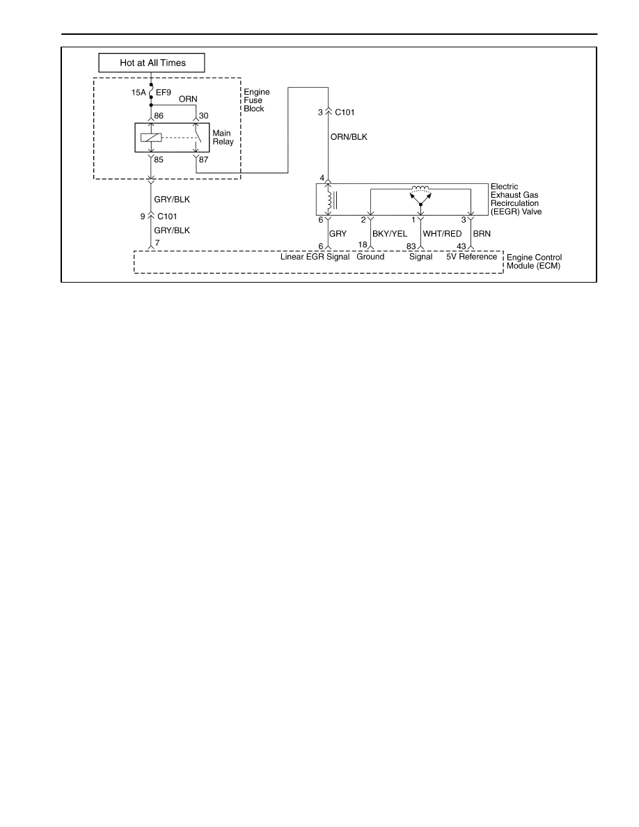
An Electric Exhaust Gas Re-circulation (EEGR) system
is used to lower oxides of nitrogen (NOX) emission lev-
els caused by high combustion temperatures. It a ac-
complishes this by feeding small amounts of exhaust
gases back into the combustion chamber. When the air/
fuel mixture is diluted with the exhaust gases, combus-
tion temperatures are reduced.
A EEGR valve is used on this system. The linear EEGR
valve is designed to accurately supply exhaust gases to
the engine without the use of intake manifold vacuum.
The valve controls exhaust flow going into the intake
manifold from the exhaust manifold fhrough an orifice
with a engine control module(ECM) controlled pintle.
The ECM controls the pintle position using inputs from
the Throttle Position (TP) and the Manifold Absolute
Pressure (MAP) sensor. The ECM then commands the
EEGR valve to operate when necessary by controlling
an ignition signal through the ECM. This can be moni-
tored on a scan tool as the Desired EEGR position.
The ECM monitors the results of its command through a
feedback signal. By sending a 5 volt reference and a
ground to the EEGR valve, a voltage signal representing
the EEGR valve pintle position is sent to the ECM. This
feedback signal can also be monitored on a scan tool
and is the actual position of the EEGR pintle. The actual
EEGR position should always be near the commanded
or Desired EEGR position.
ThisDiagnostic Trouble Code(DTC) will detect an open
or short circuit.
Conditions for Setting the DTC
D
Engine Coolant Temperature(ECT) is higher than
80
°
C(176
°
F).
D
Intake Air Temperature(IAT) is higher than 15
°
C
(59
°
F).
D
Manifold Absolute Pressure is greater than 75kPA.
D
The EEGR is higher than 3%.
D
Mass Air Flow is between 92 ~157mg/tdc.
D
Engine Speed Is Between 2,500~2,900rpm.
D
DTCs P0107, P0108, P0112, P0113, P0117, P0118,
P0122, P0123, P0131, P0300, P0335, P0336,
P0341, P0342, P1671, P1672, P1673 are NOT SET.
Action Taken When the DTC Sets
D
The Malfunction Indicator Lamp (MIL) will illuminate.
D
The ECM will record operating conditions at the time
the diagnostic fails. This information will be stored in
the Freeze Frame and Failure Records buffers.
D
A history DTC is stored.
Conditions for Clearing the MIL/DTC
D
The MIL will turn off after four consecutive ignition
cycles in which the diagnostic runs without a fault.
D
A history DTC will clear after 40 consecutive warm-up
cycles without a fault.
D
DTC(s) can be cleared by using the scan tool.

ENGINE CONTROLS 1F – 183
DAEWOO M-150 BL2
DTC P0400 – Electric Exhaust Gas Recirculation Out of Limit
Step
Action
Value(s)
Yes
No
1
Perform an Euro On-Board Diagnostic (EOBD)
System Check.
Is the system check complete?
–
Go to Step 2
Go to
“On-Board
Diagnostic
System Check”
2
1. Turn the ignition switch to with the engine OFF.
2. Install the scan tool.
3. Command the electric exhaust gas recirculation
(EEGR) valve to the specified values.
Does the Actual EEGR Position follow the desired
EEGR position?
25%, 50%,
75%, 100%
Go to Step 19
Go to Step 3
3
1. Turn the ignition switch to ON.
2. Disconnect the EEGR valve electrical connector.
3. With a test light connected to B+, probe the
ground circuit to the EEGR valve.
Does the test light illuminate?
–
Go to Step 4
Go to Step 5
4
1. Connect the test light to ground.
2. Probe the EEGR control circuit at terminal 1 to
the EEGR valve.
3. Command the EEGR valve to the specified
values using a scan tool.
After the command is raised, does the test light glow
brighter, flash or maintain a steady glow?
25%, 50%,
75%, 100%
Go to Step 6
Go to Step 7
5
Repair the open or poor connection in the EEGR
ground circuit.
Is the repair complete?
–
Go to Step 19
–
6
With a test light still connected to ground, probe the
signal circuit at terminal 1.
Does the test light illuminate?
–
Go to Step 8
Go to Step 9
7
With a test light still connected to ground, again
probe the signal circuit without commanding the
EEGR valve with the scan tool.
Does the test light illuminate?
–
Go to Step 10
Go to Step 11
8
Check the signal circuit for a short to voltage and
repair as necessary.
Is a repair necessary?
–
Go to Step 19
Go to Step 12
9
With a digital voltmeter (DVM) connected to ground,
probe the 5V reference circuit at terminal 3.
Is the voltage measured near the specified value?
5V
Go to Step 13
Go to Step 14
10
Check the control circuit for a short to battery
voltage and repair as necessary.
Is a repair necessary?
–
Go to Step 19
Go to Step 12
11
Connect the test light to B+ and again probe the
control circuit at terminal 4.
Does the test light illuminate?
–
Go to Step 15
Go to Step 16
12
Replace the engine control module (ECM).
Is the replacement complete?
–
Go to Step 19
–
13
Check the EEGR ground circuit for a poor
connection or proper terminal tension at the ECM
and repair as necessary.
Is a repair necessary?
–
Go to Step 19
Go to Step 17

1F – 184 ENGINE CONTROLS
DAEWOO M-150 BL2
DTC P0400 – Electric Exhaust Gas Recirculation Out of Limit (Cont’d)
Step
Action
Value(s)
Yes
No
14
Check the 5V reference circuit for a shortage to
vattery voltage and repair as necessary.
Is a repair necessary?
–
Go to Step 19
Go to Step 12
15
Check the control circuit for a shortage to ground
and repair as necessary.
Is a repair necessary?
–
Go to Step 19
Go to Step 12
16
Check the control circuit for an open or poor
connection at the EEGR valve electrical connector
and repair as necessary.
Is a repair necessary?
–
Go to Step 19
Go to Step 18
17
Replace the EEGR valve.
Is the replacement complete?
–
Go to Step 19
–
18
Check the ECM electrical connector for a poor
connection and repair as necessary.
Is a repair necessary?
–
Go to Step 19
Go to Step 12
19
1. Using the scan tool, clear the Diagnostic Trouble
Codes (DTCs).
2. Start the engine and idle at normal operating
temperature.
3. Operate the vehicle within the conditions for
setting the DTC as specifiec in the supporting
text.
Does the scan tool indicate that this diagnostic ran
and passed?
–
Go to Step 20
Go to Step 2
20
Check if any additional DTCs are set.
Are any DTCs displayed that have not been
diagnosed?
–
Go to
Applicable DTC
table
System OK

ENGINE CONTROLS 1F – 185
DAEWOO M-150 BL2
BLANK
1F – 186 ENGINE CONTROLS
DAEWOO M-150 BL2
MAA1F230
DIAGNOSTIC TROUBLE CODE (DTC) – P1402 ELECTRIC EXHAUST GAS
RECIRCULATION BLOCKED
Circuit Description
An Electric Exhaust Gas Re-circulation (EEGR) system
is used to lower oxides of nitrogen (NOX) emission lev-
els caused by high combustion temperatures. It a ac-
complishes this by feeding small amounts of exhaust
gases back into the combustion chamber. When the air/
fuel mixture is diluted with the exhaust gases, combus-
tion temperatures are reduced.
A EEGR valve is used on this system. The linear EEGR
valve is designed to accurately supply exhaust gases to
the engine without the use of intake manifold vacuum.
The valve controls exhaust flow going into the intake
manifold from the exhaust manifold fhrough an orifice
with a engine control module(ECM) controlled pintle.
The ECM controls the pintle position using inputs from
the Throttle Position (TP) and the Manifold Absolute
Pressure (MAP) sensor. The ECM then commands the
EEGR valve to operate when necessary by controlling
an ignition signal through the ECM. This can be moni-
tored on a scan tool as the Desired EEGR position.
The ECM monitors the results of its command through a
feedback signal. By sending a 5 volt reference and a
ground to the EEGR valve, a voltage signal representing
the EEGR valve pintle position is sent to the ECM. This
feedback signal can also be monitored on a scan tool
and is the actual position of the EEGR pintle. The actual
EEGR position should always be near the commanded
or Desired EEGR position.
ThisDiagnostic Trouble Code(DTC) will detect an open
or short circuit.
Conditions for Setting the DTC
D
Engine Coolant Temperature(ECT) is greater than
80
°
C(176
°
F).
D
Intake Air Temperature(IAT) is greater than 15
°
C
(59
°
F).
D
Manifold Absolute Pressure is greater than 75kPA.
D
The EEGR differential rate is less than 3%.
D
Mass Air Flow is between 92 ~157mg/tdc.
D
Engine Speed Is Between 2,500~2,900rpm.
D
DTCs P0107, P0108, P0112, P0113, P0117, P0118,
P0122, P0123, P0131, P0300, P0335, P0336,
P0341, P0342, P1671, P1672, P1673 are NOT SET.
D
EEGR is disabled.
Action Taken When the DTC Sets
D
The Malfunction Indicator Lamp (MIL) will illuminate.
D
The ECM will record operating conditions at the time
the diagnostic fails. This information will be stored in
the Freeze Frame and Failure Records buffers.
D
A history DTC is stored.
Conditions for Clearing the MIL/DTC
D
The MIL will turn off after four consecutive ignition
cycles in which the diagnostic runs without a fault.
D
A history DTC will clear after 40 consecutive warm-up
cycles without a fault.
D
DTC(s) can be cleared by using the scan tool.
Diagnostic Aids
Due to moisture associated with exhaust systems, the
EEGR valve may freeze and stick in cold weather at
times. After the vehicle is brought into a warm shop for
repairs, the valve warms and the problem disappears.
By watching the Actual EEGR and desired EEGR posi-
tions on a cold vehicle with a scan tool, the fault can be

ENGINE CONTROLS 1F – 187
DAEWOO M-150 BL2
easily verified. Check the Freeze Frame data to deter-
mine if the DTC set when the vehicle was cold by view-
ing the Engine Coolant Temperature (ECT).
DTC P1402 – Electric Exhaust Gas Recirculation Blocked
Step
Action
Value(s)
Yes
No
1
Perform an Euro On-Board Diagnostic (EOBD)
System Check.
Is the system check complete?
–
Go to Step 2
Go to
“On-Board
Diagnostic
System Check”
2
1. Start the engine and allow the engine to idle.
2. Install the scan tool.
3. Command the electric exhaust gas recirculation
(EEGR) valve to the specified values.
Does the engine stall or attempt to stall?
50%
Go to Step 5
Go to Step 3
3
1. Turn the ignition switch to LOCK.
2. Remove the EEGR valve assembly.
3. Inspect the EEGR valve, passages and pipe for a
restriction or damage and repair as necessary.
Is a repair necessary?
–
Go to Step 5
Go to Step 4
4
Replace the EEGR valve.
Is the replacement complete?
–
Go to Step 5
–
5
1. Start the engine.
2. Disconnect the battery for the specified time.
3. Drive the vehicle to the specified value.
4. Release the throttle and allow the vehicle to
decelerate to the specified value.
Is the EEGR Decel Filter Values less than the
specified value?
10 secnds
60mph
(97km/h)
20mph
(32km/h)
0mph
Go to Step 3
Go to Step 6
6
1. Using the scan tool, clear the Diagnostic Trouble
Codes (DTCs).
2. Start the engine and idle at normal operating
temperature.
3. Operate the vehicle within the conditions for
setting the DTC as specifiec in the supporting
text.
Does the scan tool indicate that this diagnostic ran
and passed?
–
Go to Step 7
Go to Step 2

1F – 188 ENGINE CONTROLS
DAEWOO M-150 BL2
MAA1F230
DIAGNOSTIC TROUBLE CODE (DTC) – P1403 ELECTRIC EXHAUST GAS
RECIRCULATION VALVE FAILURE
Circuit Description
An Electric Exhaust Gas Re-circulation (EEGR) system
is used to lower oxides of nitrogen (NOX) emission lev-
els caused by high combustion temperatures. It a ac-
complishes this by feeding small amounts of exhaust
gases back into the combustion chamber. When the air/
fuel mixture is diluted with the exhaust gases, combus-
tion temperatures are reduced.
A linear EEGR valve is used on this system. The linear
EEGR valve is designed to accurately supply exhaust
gases to the engine without the use of intake manifold
vacuum. The valve controls exhaust flow going into the
intake manifold from the exhaust manifold fhrough an
orifice with a engine control module(ECM) controlled
pintle. The ECM controls the pintle position using inputs
from the Throttle Position (TP) and the Manifold Abso-
lute Pressure (MAP) sensor. The ECM then commands
the EEGR valve to operate when necessary by control-
ling an ignition signal through the ECM. This can be
monitored on a scan tool as the Desired EEGR position.
The ECM monitors the results of its command through a
feedback signal. By sending a 5 volt reference and a
ground to the EEGR valve, a voltage signal representing
the EEGR valve pintle position is sent to the ECM. This
feedback signal can also be monitored on a scan tool
and is the actual position of the EEGR pintle. The actual
EEGR position should always be near the commanded
or Desired EEGR position.
ThisDiagnostic Trouble Code(DTC) will detect an open
or short circuit.
Conditions for Setting THE DTC
D
Engine Coolant Temperature(ECT) is greater than
80
°
C(176
°
F).
D
Intake Air Temperature(IAT) is greater than 15
°
C
(59
°
F).
D
Manifold Absolute Pressure is greater than 75kPA.
D
The open EEGR value is higher than 3%.
D
Mass Air Flow is between 92 ~157mg/tdc.
D
Engine Speed Is Between 2,500~2,900rpm.
D
EEGR potentiometer voltage is less than 0.4V.
D
EEGR potentiometer voltage is higher than 1.75V or
integral term of EEGR controller blocked in high or
low limit.
D
DTCs P0107, P0108, P0112, P0113, P0117, P0118,
P0122, P0123, P0131, P0300, P0335, P0336,
P0341, P0342, P1671, P1672, P1673 are NOT SET.
Action Taken When the DTC Sets
D
The Malfunction Indicator Lamp (MIL) will illuminate.
D
The ECM will record operating conditions at the time
the diagnostic fails. This information will be stored in
the Freeze Frame and Failure Records buffers.
D
A history DTC is stored.
Conditions for Clearing the MIL/DTC
D
The MIL will turn off after four consecutive ignition
cycles in which the diagnostic runs without a fault.
D
A history DTC will clear after 40 consecutive warm-up
cycles without a fault.
D
DTC(s) can be cleared by using the scan tool.
Diagnostic Aids
Due to moisture associated with exhaust systems, the
EEGR valve may freeze and stick in cold weather at
times. After the vehicle is brought into a warm shop for

ENGINE CONTROLS 1F – 189
DAEWOO M-150 BL2
repairs, the valve warms and the problem disappears.
By watching the Actual EEGR and desired EEGR posi-
tions on a cold vehicle with a scan tool, the fault can be
easily verified. Check the Freeze Frame data to deter-
mine if the DTC set when the vehicle was cold by view-
ing the Engine Coolant Temperature (ECT).
DTC P1403 – Electric Exhaust Gas Recirculation Valve Failure
Step
Action
Value(s)
Yes
No
1
Perform an Euro On-Board Diagnostic (EOBD)
System Check.
Is the system check complete?
–
Go to Step 2
Go to
“On-Board
Diagnostic
System Check”
2
1. Turn the ignition switch to with the engine OFF.
2. Install the scan tool.
3. Command the electric exhaust gas recirculation
(EEGR) valve to the specified values.
Does the Actual EEGR Position follow the desired
EEGR position?
25%, 50%,
75%, 100%
Go to Step 19
Go to Step 3
3
1. Turn the ignition switch to ON.
2. Disconnect the EEGR valve electrical connector.
3. With a test light connected to B+, probe the
ground circuit to the EEGR valve.
Does the test light illuminate?
–
Go to Step 4
Go to Step 5
4
1. Connect the test light to ground.
2. Probe the EEGR control circuit at terminal 1 to
the EEGR valve.
3. Command the EEGR valve to the specified
values using a scan tool.
After the command is raised, does the test light glow
brighter, flash or maintain a steady glow?
25%, 50%,
75%, 100%
Go to Step 6
Go to Step 7
5
Repair the open or poor connection in the EEGR
ground circuit.
Is the repair complete?
–
Go to Step 19
–
6
With a test light still connected to ground, probe the
signal circuit at terminal 1.
Does the test light illuminate?
–
Go to Step 8
Go to Step 9
7
With a test light still connected to ground, again
probe the signal circuit without commanding the
EEGR valve with the scan tool.
Does the test light illuminate?
–
Go to Step 10
Go to Step 11
8
Check the signal circuit for a short to voltage and
repair as necessary.
Is a repair necessary?
–
Go to Step 19
Go to Step 12
9
With a digital voltmeter (DVM) connected to ground,
probe the 5V reference circuit at terminal 3.
Is the voltage measured near the specified value?
5V
Go to Step 13
Go to Step 14
10
Check the control circuit for a short to battery
voltage and repair as necessary.
Is a repair necessary?
–
Go to Step 19
Go to Step 12
11
Connect the test light to B+ and again probe the
control circuit at terminal 4.
Does the test light illuminate?
–
Go to Step 15
Go to Step 16
12
Replace the engine control module (ECM).
Is the replacement complete?
–
Go to Step 19
–

1F – 190 ENGINE CONTROLS
DAEWOO M-150 BL2
DTC P1403 – Electric Exhaust Gas Recirculation Valve Failure (Cont’d)
Step
Action
Value(s)
Yes
No
13
Check the EEGR ground circuit for a poor
connection or proper terminal tension at the ECM
and repair as necessary.
Is a repair necessary?
–
Go to Step 19
Go to Step 17
14
Check the 5V reference circuit for a shortage to
battery voltage and repair as necessary.
Is a repair necessary?
–
Go to Step 19
Go to Step 12
15
Check the control circuit for a shortage to ground
and repair as necessary.
Is a repair necessary?
–
Go to Step 19
Go to Step 12
16
Check the control circuit for an open or poor
connection at the EEGR valve electrical connector
and repair as necessary.
Is a repair necessary?
–
Go to Step 19
Go to Step 18
17
Replace the EEGR valve.
Is the replacement complete?
–
Go to Step 19
–
18
Check the ECM electrical connector for a poor
connection and repair as necessary.
Is a repair necessary?
–
Go to Step 19
Go to Step 12
19
1. Using the scan tool, clear the Diagnostic Trouble
Codes (DTCs).
2. Start the engine and idle at normal operating
temperature.
3. Operate the vehicle within the conditions for
setting the DTC as specifiec in the supporting
text.
Does the scan tool indicate that this diagnostic ran
and passed?
–
Go to Step 20
Go to Step 2
20
Check if any additional DTCs are set.
Are any DTCs displayed that have not been
diagnosed?
–
Go to
Applicable DTC
table
System OK

ENGINE CONTROLS 1F – 191
DAEWOO M-150 BL2
BLANK

1F – 192 ENGINE CONTROLS
DAEWOO M-150 BL2
MAA1F230
DIAGNOSTIC TROUBLE CODE (DTC) – P0404 ELECTRIC EXHAUST GAS
RECIRCULATION OPENED
Circuit Description
An Electric Exhaust Gas Re-circulation (EEGR) system
is used to lower oxides of nitrogen (NOX) emission lev-
els caused by high combustion temperatures. It a ac-
complishes this by feeding small amounts of exhaust
gases back into the combustion chamber. When the air/
fuel mixture is diluted with the exhaust gases, combus-
tion temperatures are reduced.
A linear EEGR valve is used on this system. The linear
EEGR valve is designed to accurately supply exhaust
gases to the engine without the use of intake manifold
vacuum. The valve controls exhaust flow going into the
intake manifold from the exhaust manifold fhrough an
orifice with a engine control module(ECM) controlled
pintle. The ECM controls the pintle position using inputs
from the Throttle Position (TP) and the Manifold Abso-
lute Pressure (MAP) sensor. The ECM then commands
the EEGR valve to operate when necessary by control-
ling an ignition signal through the ECM. This can be
monitored on a scan tool as the Desired EEGR position.
The ECM monitors the results of its command through a
feedback signal. By sending a 5 volt reference and a
ground to the EEGR valve, a voltage signal representing
the EEGR valve pintle position is sent to the ECM. This
feedback signal can also be monitored on a scan tool
and is the actual position of the EEGR pintle. The actual
EEGR position should always be near the commanded
or Desired EEGR position.
ThisDiagnostic Trouble Code(DTC) will detect an open
or short circuit.
Conditions for Setting THE DTC
D
EEGR circuit low voltage.
Action Taken When the DTC Sets
D
The Malfunction Indicator Lamp (MIL) will illuminate.
D
The ECM will record operating conditions at the time
the diagnostic fails. This information will be stored in
the Freeze Frame and Failure Records buffers.
D
A history DTC is stored.
D
EEGR is disabled.
Conditions for Clearing the MIL/DTC
D
The MIL will turn off after four consecutive ignition
cycles in which the diagnostic runs without a fault.
D
A history DTC will clear after 40 consecutive warm-up
cycles without a fault.
D
DTC(s) can be cleared by using the scan tool.
Diagnostic Aids
Due to moisture associated with exhaust systems, the
EEGR valve may freeze and stick in cold weather at
times. After the vehicle is brought into a warm shop for
repairs, the valve warms and the problem disappears.
By watching the Actual EEGR and desired EEGR posi-
tions on a cold vehicle with a scan tool, the fault can be
easily verified. Check the Freeze Frame data to deter-
mine if the DTC set when the vehicle was cold by view-
ing the Engine Coolant Temperature (ECT).

ENGINE CONTROLS 1F – 193
DAEWOO M-150 BL2
DTC P0404 – Electric Exhaust Gas Recirculation Opened
Step
Action
Value(s)
Yes
No
1
Perform an Euro On-Board Diagnostic (EOBD)
System Check.
Is the system check complete?
–
Go to Step 2
Go to
“On-Board
Diagnostic
System Check”
2
1. Turn the ignition switch to with the engine OFF.
2. Install the scan tool.
3. Command the electric exhaust gas recirculation
(EEGR) valve to the specified values.
Does the Actual EEGR Position follow the desired
EEGR position?
25%, 50%,
75%, 100%
Go to Step 19
Go to Step 3
3
1. Turn the ignition switch to ON.
2. Disconnect the EEGR valve electrical connector.
3. With a test light connected to B+, probe the
ground circuit to the EEGR valve.
Does the test light illuminate?
–
Go to Step 4
Go to Step 5
4
1. Connect the test light to ground.
2. Probe the EEGR control circuit at terminal 1 to
the EEGR valve.
3. Command the EEGR valve to the specified
values using a scan tool.
After the command is raised, does the test light glow
brighter, flash or maintain a steady glow?
25%, 50%,
75%, 100%
Go to Step 6
Go to Step 7
5
Repair the open or poor connection in the EEGR
ground circuit.
Is the repair complete?
–
Go to Step 19
–
6
With a test light still connected to ground, probe the
signal circuit at terminal 1.
Does the test light illuminate?
–
Go to Step 8
Go to Step 9
7
With a test light still connected to ground, again
probe the signal circuit without commanding the
EEGR valve with the scan tool.
Does the test light illuminate?
–
Go to Step 10
Go to Step 11
8
Check the signal circuit for a short to voltage and
repair as necessary.
Is a repair necessary?
–
Go to Step 19
Go to Step 12
9
With a digital voltmeter (DVM) connected to ground,
probe the 5V reference circuit at terminal 3.
Is the voltage measured near the specified value?
5V
Go to Step 13
Go to Step 14
10
Check the control circuit for a short to battery
voltage and repair as necessary.
Is a repair necessary?
–
Go to Step 19
Go to Step 12
11
Connect the test light to B+ and again probe the
control circuit at terminal 4.
Does the test light illuminate?
–
Go to Step 15
Go to Step 16
12
Replace the engine control module (ECM).
Is the replacement complete?
–
Go to Step 19
–
13
Check the EEGR ground circuit for a poor
connection or proper terminal tension at the ECM
and repair as necessary.
Is a repair necessary?
–
Go to Step 19
Go to Step 17

1F – 194 ENGINE CONTROLS
DAEWOO M-150 BL2
DTC P0404 – Electric Exhaust Gas Recirculation Opened (Cont’d)
Step
Action
Value(s)
Yes
No
14
Check the 5V reference circuit for a shortage to
battery voltage and repair as necessary.
Is a repair necessary?
–
Go to Step 19
Go to Step 12
15
Check the control circuit for a shortage to ground
and repair as necessary.
Is a repair necessary?
–
Go to Step 19
Go to Step 12
16
Check the control circuit for an open or poor
connection at the EEGR valve electrical connector
and repair as necessary.
Is a repair necessary?
–
Go to Step 19
Go to Step 18
17
Replace the EEGR valve.
Is the replacement complete?
–
Go to Step 19
–
18
Check the ECM electrical connector for a poor
connection and repair as necessary.
Is a repair necessary?
–
Go to Step 19
Go to Step 12
19
1. Using the scan tool, clear the Diagnostic Trouble
Codes (DTCs).
2. Start the engine and idle at normal operating
temperature.
3. Operate the vehicle within the conditions for
setting the DTC as specifiec in the supporting
text.
Does the scan tool indicate that this diagnostic ran
and passed?
–
Go to Step 20
Go to Step 2
20
Check if any additional DTCs are set.
Are any DTCs displayed that have not been
diagnosed?
–
Go to
Applicable DTC
table
System OK

ENGINE CONTROLS 1F – 195
DAEWOO M-150 BL2
BLANK

1F – 196 ENGINE CONTROLS
DAEWOO M-150 BL2
MAA1F230
DIAGNOSTIC TROUBLE CODE (DTC) – P1404 ELECTRIC EXHAUST GAS
RECIRCULATION CLOSED
Circuit Description
An Electric Exhaust Gas Re-circulation (EEGR) system
is used to lower oxides of nitrogen (NOX) emission lev-
els caused by high combustion temperatures. It a ac-
complishes this by feeding small amounts of exhaust
gases back into the combustion chamber. When the air/
fuel mixture is diluted with the exhaust gases, combus-
tion temperatures are reduced.
A linear EEGR valve is used on this system. The linear
EEGR valve is designed to accurately supply exhaust
gases to the engine without the use of intake manifold
vacuum. The valve controls exhaust flow going into the
intake manifold from the exhaust manifold fhrough an
orifice with a engine control module(ECM) controlled
pintle. The ECM controls the pintle position using inputs
from the Throttle Position (TP) and the Manifold Abso-
lute Pressure (MAP) sensor. The ECM then commands
the EEGR valve to operate when necessary by control-
ling an ignition signal through the ECM. This can be
monitored on a scan tool as the Desired EEGR position.
The ECM monitors the results of its command through a
feedback signal. By sending a 5 volt reference and a
ground to the EEGR valve, a voltage signal representing
the EEGR valve pintle position is sent to the ECM. This
feedback signal can also be monitored on a scan tool
and is the actual position of the EEGR pintle. The actual
EEGR position should always be near the commanded
or Desired EEGR position.
ThisDiagnostic Trouble Code(DTC) will detect an open
or short circuit.
Conditions for Setting THE DTC
D
EEGR circuit high voltage.
Action Taken When The DTCs Sets
D
The Malfunction Indicator Lamp (MIL) will illuminate.
D
The ECM will record operating conditions at the time
the diagnostic fails. This information will be stored in
the Freeze Frame and Failure Records buffers.
D
A history DTC is stored.
D
EEGR is disabled.
Conditions for Clearing the MIL/DTC
D
The MIL will turn off after four consecutive ignition
cycles in which the diagnostic runs without a fault.
D
A history DTC will clear after 40 consecutive warm-up
cycles without a fault.
D
DTC(s) can be cleared by using the scan tool.
D
Disconnecting the ECM battery feed for more than 10
seconds.
Diagnostic Aids
Due to moisture associated with exhaust systems, the
EEGR valve may freeze and stick in cold weather at
times. After the vehicle is brought into a warm shop for
repairs, the valve warms and the problem disappears.
By watching the Actual EEGR and desired EEGR posi-
tions on a cold vehicle with a scan tool, the fault can be
easily verified. Check the Freeze Frame data to deter-
mine if the DTC set when the vehicle was cold by view-
ing the Engine Coolant Temperature (ECT).

ENGINE CONTROLS 1F – 197
DAEWOO M-150 BL2
DTC P1404 – Electric Exhaust Gas Recirculation Opend
Step
Action
Value(s)
Yes
No
1
Perform an Euro On-Board Diagnostic (EOBD)
System Check.
Is the system check complete?
–
Go to Step 2
Go to
“On-Board
Diagnostic
System Check”
2
1. Turn the ignition switch to with the engine OFF.
2. Install the scan tool.
3. Command the electric exhaust gas recirculation
(EEGR) valve to the specified values.
Does the Actual EEGR Position follow the desired
EEGR position?
25%, 50%,
75%, 100%
Go to Step 19
Go to Step 3
3
1. Turn the ignition switch to ON with the engine
OFF.
2. Disconnect the EEGR valve electrical connector.
3. With a digital voltmeter (DVM) connected to
ground, probe the 5volt reference circuit at
terminal 2 to the EEGR valve.
Does the DVM read near the specified value?
5V
Go to Step 4
Go to Step 5
4
Jumper the 5 volt reference circuit to the signal
circuit at terminals 2 and 3.
Does the actual EEGR position display the specified
value ?
100%
Go to Step 6
Go to Step 7
5
1. Connect the test light to B+.
2. Probe the 5 volt reference circuit to the EEGR
valve.
Does the test light illuminate?
–
Go to Step 6
Go to Step 7
6
Check the 5 volt reference and signal circuit for a
poor connection or proper terminal tension and
repair as necessary.
Is a repair necessary?
–
Go to Step 12
Go to Step 7
7
1. Connect the test light to B+.
2. Probe the signal circuit at terminal 1 to the EEGR
valve.
Does the test light illuminate?
–
Go to Step 8
Go to Step 9
8
Check for a high voltage in the EEGR valve 5 volt
reference circuit and repair as necessary.
Is a repair necessary?
–
Go to Step 12
Go to Step 9
9
Replace the EEGR valve.
Is a replacement complete?
–
Go to Step 12
–
10
Check for a high voltage in the EEGR valve signal
circuit and repair as necessary
Is a repair necessary?
–
Go to Step 12
Go to Step 11
11
Replace the engine control module(ECM).
Is a replacement complete?
–
Go to Step 12
–
12
1. Using the scan tool, clear the Diagnostic Trouble
Codes (DTCs).
2. Start the engine and idle at normal operating
temperature.
3. Operate the vehicle within the conditions for
setting the DTC as specifiec in the supporting
text.
Does the scan tool indicate that this diagnostic ran
and passed?
–
Go to Step 13
Go to Step 2

1F – 198 ENGINE CONTROLS
DAEWOO M-150 BL2
DTC P1404 – Electric Exhaust Gas Recirculation Opend (Cont’d)
Step
Action
Value(s)
Yes
No
13
Check if any additional DTCs are set.
Are any DTCs displayed that have not been
diagnosed?
–
Go to
Applicable DTC
table
System OK

ENGINE CONTROLS 1F – 199
DAEWOO M-150 BL2
BLANK

1F – 200 ENGINE CONTROLS
DAEWOO M-150 BL2
MAA1F230
DIAGNOSTIC TROUBLE CODE (DTC) – P0405 EEGR PINTLE POSITION
SENSOR LOW VOLTAGE
Circuit Description
An Electric Exhaust Gas Re-circulation (EEGR) system
is used to lower oxides of nitrogen (NOX) emission lev-
els caused by high combustion temperatures. It a ac-
complishes this by feeding small amounts of exhaust
gases back into the combustion chamber. When the air/
fuel mixture is diluted with the exhaust gases, combus-
tion temperatures are reduced.
A linear EEGR valve is used on this system. The linear
EEGR valve is designed to accurately supply exhaust
gases to the engine without the use of intake manifold
vacuum. The valve controls exhaust flow going into the
intake manifold from the exhaust manifold fhrough an
orifice with a engine control module(ECM) controlled
pintle. The ECM controls the pintle position using inputs
from the Throttle Position (TP) and the Manifold Abso-
lute Pressure (MAP) sensor. The ECM then commands
the EEGR valve to operate when necessary by control-
ling an ignition signal through the ECM. This can be
monitored on a scan tool as the Desired EEGR position.
The ECM monitors the results of its command through a
feedback signal. By sending a 5 volt reference and a
ground to the EEGR valve, a voltage signal representing
the EEGR valve pintle position is sent to the ECM. This
feedback signal can also be monitored on a scan tool
and is the actual position of the EEGR pintle. The actual
EEGR position should always be near the commanded
or Desired EEGR position.
ThisDiagnostic Trouble Code(DTC) will detect an open
or short circuit.
Conditions for Setting THE DTC
D
EEGR voltage is less than 0.01V.
D
EEGR potentiometer circuit low voltage.
Action Taken When The DTCs Sets
D
The Malfunction Indicator Lamp (MIL) will illuminate.
D
The ECM will record operating conditions at the time
the diagnostic fails. This information will be stored in
the Freeze Frame and Failure Records buffers.
D
A history DTC is stored.
D
EEGR is disabled.
Conditions for Clearing the MIL/DTC
D
The MIL will turn off after four consecutive ignition
cycles in which the diagnostic runs without a fault.
D
A history DTC will clear after 40 consecutive warm-up
cycles without a fault.
D
DTC(s) can be cleared by using the scan tool.
D
Disconnecting the ECM battery feed for more than 10
seconds.
Diagnostic Aids
Due to moisture associated with exhaust systems, the
EEGR valve may freeze and stick in cold weather at
times. After the vehicle is brought into a warm shop for
repairs, the valve warms and the problem disappears.
By watching the Actual EEGR and desired EEGR posi-
tions on a cold vehicle with a scan tool, the fault can be
easily verified. Check the Freeze Frame data to deter-
mine if the DTC set when the vehicle was cold by view-
ing the Engine Coolant Temperature (ECT).

ENGINE CONTROLS 1F – 201
DAEWOO M-150 BL2
DTC P0405 – EEGR Pintle Position Sensor Low Voltage
Step
Action
Value(s)
Yes
No
1
Perform an Euro On-Board Diagnostic (EOBD)
System Check.
Is the system check complete?
–
Go to Step 2
Go to
“On-Board
Diagnostic
System Check”
2
1. Turn the ignition switch to with the engine OFF.
2. Install the scan tool.
3. Command the electric exhaust gas recirculation
(EEGR) valve to the specified values.
Does the Actual EEGR Position follow the desired
EEGR position?
25%, 50%,
75%, 100%
Go to Step 19
Go to Step 3
3
1. Turn the ignition switch to ON with the engine
OFF.
2. Disconnect the EEGR valve electrical connector.
3. With a digital voltmeter (DVM) connected to
ground, probe the 5volt reference circuit at
terminal 3 to the EEGR valve.
Does the DVM read near the specified value?
–0.01V
Go to Step 4
Go to Step 5
4
Jumper the 5 volt reference circuit to the signal
circuit at terminals 2 and 3.
Does the actual EEGR position display the specified
value ?
100%
Go to Step 6
Go to Step 7
5
1. Connect the test light to B+.
2. Probe the 5 volt reference circuit to the EEGR
valve.
Does the test light illuminate?
–
Go to Step 6
Go to Step 7
6
Check the 5 volt reference and signal circuit for a
poor connection or proper terminal tension and
repair as necessary.
Is a repair necessary?
–
Go to Step 12
Go to Step 7
7
1. Connect the test light to B+.
2. Probe the signal circuit at terminal 2 to the EEGR
valve.
Does the test light illuminate?
–
Go to Step 8
Go to Step 9
8
Check for a low voltage in the EEGR valve 5 volt
reference circuit and repair as necessary.
Is a repair necessary?
–
Go to Step 12
Go to Step 9
9
Replace the EEGR valve
Is a replacement complete?
–
Go to Step 12
–
10
Check for a low voltage in the EEGR valve signal
circuit and repair as necessary
Is a repair necessary?
–
Go to Step 12
Go to Step 11
11
Replace the engine control module(ECM).
Is a replacement complete?
–
Go to Step 12
–
12
1. Using the scan tool, clear the Diagnostic Trouble
Codes (DTCs).
2. Start the engine and idle at normal operating
temperature.
3. Operate the vehicle within the conditions for
setting the DTC as specifiec in the supporting
text.
Does the scan tool indicate that this diagnostic ran
and passed?
–
Go to Step 13
Go to Step 2

1F – 202 ENGINE CONTROLS
DAEWOO M-150 BL2
DTC P0405 – EEGR Pintle Position Sensor Low Voltage (Cont’d)
Step
Action
Value(s)
Yes
No
13
Check if any additional DTCs are set.
Are any DTCs displayed that have not been
diagnosed?
–
Go to
Applicable DTC
table
System OK

ENGINE CONTROLS 1F – 203
DAEWOO M-150 BL2
BLANK

1F – 204 ENGINE CONTROLS
DAEWOO M-150 BL2
MAA1F230
DIAGNOSTIC TROUBLE CODE (DTC) – P0406 EEGR PINTLE POSITION
SENSOR HIGH VOLTAGE
Circuit Description
An Electric Exhaust Gas Re-circulation (EEGR) system
is used to lower oxides of nitrogen (NOX) emission lev-
els caused by high combustion temperatures. It a ac-
complishes this by feeding small amounts of exhaust
gases back into the combustion chamber. When the air/
fuel mixture is diluted with the exhaust gases, combus-
tion temperatures are reduced.
A linear EEGR valve is used on this system. The linear
EEGR valve is designed to accurately supply exhaust
gases to the engine without the use of intake manifold
vacuum. The valve controls exhaust flow going into the
intake manifold from the exhaust manifold fhrough an
orifice with a engine control module(ECM) controlled
pintle. The ECM controls the pintle position using inputs
from the Throttle Position (TP) and the Manifold Abso-
lute Pressure (MAP) sensor. The ECM then commands
the EEGR valve to operate when necessary by control-
ling an ignition signal through the ECM. This can be
monitored on a scan tool as the Desired EEGR position.
The ECM monitors the results of its command through a
feedback signal. By sending a 5 volt reference and a
ground to the EEGR valve, a voltage signal representing
the EEGR valve pintle position is sent to the ECM. This
feedback signal can also be monitored on a scan tool
and is the actual position of the EEGR pintle. The actual
EEGR position should always be near the commanded
or Desired EEGR position.
This Diagnostic Trouble Code(DTC) will detect an open
or short circuit.
Conditions for Setting THE DTC
D
EEGR voltage is higher than 4.99V.
D
EEGR potentiometer circuit high voltage.
Action Taken When The DTCs Sets
D
The Malfunction Indicator Lamp (MIL) will illuminate.
D
The ECM will record operating conditions at the time
the diagnostic fails. This information will be stored in
the Freeze Frame and Failure Records buffers.
D
A history DTC is stored.
D
EEGR is disabled.
Conditions for Clearing the MIL/DTC
D
The MIL will turn off after four consecutive ignition
cycles in which the diagnostic runs without a fault.
D
A history DTC will clear after 40 consecutive warm-up
cycles without a fault.
D
DTC(s) can be cleared by using the scan tool.
Diagnostic Aids
Due to moisture associated with exhaust systems, the
EEGR valve may freeze and stick in cold weather at
times. After the vehicle is brought into a warm shop for
repairs, the valve warms and the problem disappears.
By watching the Actual EEGR and desired EEGR posi-
tions on a cold vehicle with a scan tool, the fault can be
easily verified. Check the Freeze Frame data to deter-
mine if the DTC set when the vehicle was cold by view-
ing the Engine Coolant Temperature (ECT).

ENGINE CONTROLS 1F – 205
DAEWOO M-150 BL2
DTC P0406 – EEGR Pintle Position Sensor High Voltage
Step
Action
Value(s)
Yes
No
1
Perform an Euro On-Board Diagnostic (EOBD)
System Check.
Is the system check complete?
–
Go to Step 2
Go to
“On-Board
Diagnostic
System Check”
2
1. Turn the ignition switch to with the engine OFF.
2. Install the scan tool.
3. Command the electric exhaust gas recirculation
(EEGR) valve to the specified values.
Does the Actual EEGR Position follow the desired
EEGR position?
25%, 50%,
75%, 100%
Go to Step 19
Go to Step 3
3
1. Turn the ignition switch to ON with the engine
OFF.
2. Disconnect the EEGR valve electrical connector.
3. With a digital voltmeter (DVM) connected to
ground, probe the 5volt reference circuit at
terminal 3 to the EEGR valve.
Does the DVM read near the specified value?
More than 5V
Go to Step 4
Go to Step 5
4
Jumper the 5 volt reference circuit to the signal
circuit at terminals 2 and 3.
Does the actual EEGR position display the specified
value ?
100%
Go to Step 6
Go to Step 7
5
1. Connect the test light to B+.
2. Probe the 5 volt reference circuit to the EEGR
valve.
Does the test light illuminate?
–
Go to Step 6
Go to Step 7
6
Check the 5 volt reference and signal circuit for a
poor connection or proper terminal tension and
repair as necessary.
Is a repair necessary?
–
Go to Step 12
Go to Step 7
7
1. Connect the test light to B+.
2. Probe the signal circuit at terminal 2 to the EEGR
valve.
Does the test light illuminate?
–
Go to Step 8
Go to Step 9
8
Check for a high voltage in the EEGR valve 5 volt
reference circuit and repair as necessary.
Is a repair necessary?
–
Go to Step 12
Go to Step 9
9
Replace the EEGR valve
Is a replacement complete?
–
Go to Step 12
–
10
Check for a high voltage in the EEGR valve signal
circuit and repair as necessary
Is a repair necessary?
–
Go to Step 12
Go to Step 11
11
Replace the engine control module(ECM).
Is a replacement complete?
–
Go to Step 12
–
12
1. Using the scan tool, clear the Diagnostic Trouble
Codes (DTCs).
2. Start the engine and idle at normal operating
temperature.
3. Operate the vehicle within the conditions for
setting the DTC as specifiec in the supporting
text.
Does the scan tool indicate that this diagnostic ran
and passed?
–
Go to Step 13
Go to Step 2

1F – 206 ENGINE CONTROLS
DAEWOO M-150 BL2
DTC P0406 – EEGR Pintle Position Sensor High Voltage (Cont’d)
Step
Action
Value(s)
Yes
No
13
Check if any additional DTCs are set.
Are any DTCs displayed that have not been
diagnosed?
–
Go to
Applicable DTC
table
System OK

ENGINE CONTROLS 1F – 207
DAEWOO M-150 BL2
BLANK

1F – 208 ENGINE CONTROLS
DAEWOO M-150 BL2
DIAGNOSTIC TROUBLE CODE (DTC) – P0420 CATALYST LOW EFFICIENCY
Circuit Description
In order to control exhaust emissions of Hydrocarbons
(HC), Carbon Monoxide (CO) and Nitrogen Oxide
(NOx), a Three-Way Catalytic Converter (TWC) is used.
The catalyst within the converter promotes a chemical
reaction which oxidizes the HC and CO present in the
exhaust gas, converting them into harmless water vapor
and carbon dioxide, it also reduces NOx, converting it
into nitrogen. The catalytic converter also has the ability
to store oxygen. The Engine Control Module (ECM) has
the capability to monitor this process using a Heated
Oxygen Sensor (HO2S) located in the exhaust stream
past the TWC. The HO2S produces an output signal
which indicates the oxygen storage capacity of the cata-
lyst; this in turn indicates the catalyst’s ability to convert
exhaust emissions effectively. The ECM monitors the
catalyst efficiency by first allowing the catalyst to heat
up, waiting for a stabilization period while the engine is
idling, and then adding and removing fuel while monitor-
ing the reaction of the HO2S. When the catalyst is func-
tioning properly, the HO2S response to the extra fuel is
slow compared to the Oxygen Sensor (O2S). When the
HO2S response is close to that of the O2S, the Oxygen
storage capability or efficiency of the catalyst is consid-
ered to be bad, and the Malfunction Indicator Lamp
(MIL) will illuminate.
Conditions for Setting the DTC
D
Oxygen Sensor Capacity test condition:
D
Closed loop stoichiometry.
D
Engine is running more than 300 seconds.
D
Airflow is between 25~50kg/h.
D
Engine Coolant Temperature (ECT) is more than
70
°
C(176
°
F) .
D
Engine speed between 2,400rpm and 3,000rpm.
D
Vehicle speed is between 64km/h(28.6mph) and
80km/h(49.7mph).
Note: Test is aborted for this idle if:
D
Change in engine speed is greater than 80 rpm.
D
A/C status changed.
D
Cooling fan status changed.
D
Insufficient air/fuel shift.
D
DTC(s) P0106, P0107, P0108, P0117, P0118,
P0122, P0123, P0125, P0131, P0132, P0133,
P1133, P0134, P1134, P0137, P0138, P0140,
P0141, P1167, P1171, P0171, P0172, P0201,
P0202, P0203, P0204, P0300, P0336, P0337,
P0341, P0342, P0351, P0352, P0402, P0404,
P0405, P0406, P0506, P0507, and P0562 are NOT
SET.
Action Taken When the DTC Sets
D
The Malfunction Indicator Lamp (MIL) will illuminate.
D
The ECM will record operating conditions at the time
the diagnostic fails. This information will be stored in
the Freeze Frame and Failure Records buffers.
D
A history DTC is stored.
Conditions for Clearing the MIL/DTC
D
The MIL will turn off after four consecutive ignition
cycles in which the diagnostic runs without a fault.
D
A history DTC will clear after 40 consecutive warm-up
cycles without a fault.
D
DTC(s) can be cleared by using the scan tool.
Diagnostic Aids
The catalyst test may abort due to a change in the en-
gine load. Do not change the engine load (i.e. A/C, cool-
ant fan, heater motor) while a catalyst test is in progress.
An intermittent problem may be caused by a poor con-
nection, rubbed-through wire insulation, or a wire that is
broken inside the insulation.
Any circuitry, that is suspected as causing the intermit-
tent complaint, should be thoroughly checked for the fol-
lowing conditions:
D
Backed-out terminals
D
Improper mating
D
Broken locks
D
Improperly formed
D
Damaged terminals
D
Poor terminal-to-wire connection.

ENGINE CONTROLS 1F – 209
DAEWOO M-150 BL2
DTC P0420 – Catalyst Low Efficiency
Step
Action
Value(s)
Yes
No
1
Perform an Euro On-Board Diagnostic (EOBD)
System Check.
Was the check performed?
–
Go to Step 2
Go to
“On-Board
Diagnostic
System Check”
2
1. Install a scan tool to the Data link Connector
(DLC).
2. Turn the ignition ON.
Are any component Diagnostic Trouble Codes
(DTCs) set?
–
Go to
Applicable DTC
table
Go to Step 3
3
1. Visually/physically check the following:
2. Exhaust system for a leak.
3. Heated Oxygen Sensor (HO2S).
Is a problem found?
–
Go to Step 4
Go to Step 5
4
Repair the exhaust system as needed.
Is the repair complete?
–
Go to Step 6
–
5
Replace the Three Way Catalytic Converter (TWC).
Is the repair complete?
–
Go to Step 6
–
6
1. Using the scan tool, clear the Diagnostic Trouble
Codes (DTCs).
2. Start the engine and idle at normal operating
temperature.
3. Operate the vehicle within the Conditions for
setting this DTC as specified in the supporting
text.
Does the scan tool indicate that this diagnostic has
run and passed?
–
Go to Step 7
Go to Step 2
7
Check if any additional DTCs are set.
Are any DTCs displayed that have not been
diagnosed?
–
Go to
Applicable DTC
table
System OK

1F – 210 ENGINE CONTROLS
DAEWOO M-150 BL2
MAA1F240
DIAGNOSTIC TROUBLE CODE (DTC) – P0444 EVAP PURGE CONTROL
CIRCUIT NO SIGNAL
Circuit Description
The evaporative emission (EVAP) system includes the
following components :
D
Fuel tank.
D
EVAP vent solenoid.
D
Fuel pipes and hoses.
D
Fuel vapor lines.
D
Fuel cap.
D
EVAP canister.
D
Purge lines.
D
EVAP canister purge valve.
D
EVAP service port.
The evaporative emission system is checked by apply-
ing vacuum to the EVAP system and monitoring for a
vacuum decay. The engine control module(ECM) moni-
tors the vacuum level through the fuel tank pressure
sensor signal. At the appropriate time, the EVAP canis-
ter purge valve and the EVAP vent solenoid are turned
on, allowing the engine to draw a small vacuum on the
entire EVAP system. After the desired vacuum level has
been achieved, the EVAP canister purge valve is turned
OFF, sealing the system. If a sufficient vacuum level
cannot be achieved, a large leak is indicated. This can
be caused by the following conditions :
Missing or faulty fuel cap.
Disconnected or faulty fuel tank pressure sensor.
Disconnected, damaged, pinched, or blocked EVAP
purge line.
Disconnected or faulty EVAP canister purge valve.
Disconnected or faulty EVAP vent solenoid.
Open ignition feed circuit to the EVAP vent or purge so-
lenoid.
Damaged EVAP canister.
Leaking fuel sensor assembly O-ring.
Leaking fuel tank or fuel filler beck.
Any of the above conditions can set DTC P0444.
The test is failed if the tank vacuum is less than 10 in
H20 for 15 seconds and the manifold vacuum integral is
greater than 49512 (proportional to purge mass from the
tank).
Conditions for Setting the DTC
D
Intake Air Temperature(IAT) is between 4
°
C and
34
°
C(39
°
F and 93
°
F).at engine start up.
D
Engine Coolant Temperature(ECT) is between 4
°
C
and 34
°
C(39
°
F and 93
°
F).at engine start up.
D
Barometric pressure (BARO) is greater than 68kPA.
D
IAT is not more than 8
°
C(46
°
F) greater than the ECT
at start up.
D
Fuel level is between 10% and 90%.
D
The throttle position (TP) sensor is less than or equal
to 100%.
D
No fuel slosh, and the change in fuel level percent is
21 counts on 0.125 sec.
D
Manifold vacuum is greater than or equal to 10kPA.
D
Fuel level or change in tank pressure is less than or
equal to 24.9 in H2O.
D
System voltage is between 11V and 16V.

ENGINE CONTROLS 1F – 211
DAEWOO M-150 BL2
D
The EVAP system in unable to achieve or maintain
vacuum during the diagnostic test. The amount of
decay will vary within the fuel level.
Action Taken When The DTCs Sets
D
The Malfunction Indicator Lamp (MIL) will illuminate.
D
The ECM will record operating conditions at the time
the diagnostic fails. This information will be stored in
the Freeze Frame and Failure Records buffers.
D
A history DTC is stored.
Conditions for Clearing the MIL/DTC
D
The MIL will turn off after four consecutive ignition
cycles in which the diagnostic runs without a fault.
D
A history DTC will clear after 40 consecutive warm-up
cycles without a fault.
D
DTC(s) can be cleared by using the scan tool.
Diagnostic Aids
Although this DTC is considered a type. A diagnostic, it
acts like a type B diagnostic under certain conditions.
Whenever this diagnostic reports the system has
passed, or if the battery is disconnected, the diagnostic
must fail twice before setting a DTC. The initial failure is
not reported to the diagnostic executive or displayed on
a scan tool. A passing system always reports to the
diagnostic executive immediately.
Check for the following conditions :
D
Missing or damaged fuel cap.
D
Missing or damaged O-rings at fuel vapor and EVAP
purge line canister fittings.
D
Cracked or punctured EVAP canister.
D
Damaged source vacuum line, EVAP purge line,
EVAP vent hose or fuel tank vapor line.
D
Poor connection at the ECM. Inspect the harness
connectors for the following conditions.
D
Backed-out terminals.
D
Improper mating.
D
Broken locks.
D
Improperly formed.
D
Damaged terminals.
D
Poor terminal-to-wire connection.
D
Damaged harness. Inspect the wiring harness to the
EVAP vent solenoid, EVAP canister purge valve, and
the fuel tank pressure sensor for an intermittent open
or short circuit.
D
Kinked, pinched or plugged vacuum source, EVAP
purge, or fuel tank vapor line. Verify that the lines are
not restricted.

1F – 212 ENGINE CONTROLS
DAEWOO M-150 BL2
DTC P0444 – EVAP Purge Control Circuit No Signal
Step
Action
Value(s)
Yes
No
1
Perform an Euro On-Board Diagnostic (EOBD)
System Check.
Is the system check complete?
–
Go to Step 2
Go to
“On-Board
Diagnostic
System Check”
2
1. Disconnect the evaporative emission (EVAP)
canister purge valve connector.
2. Connect a test light between the EVAP canister
purge valve connector terminal 2 and battery
positive.
Is the test light ON?
–
Go to Step 3
Go to Step 5
3
1. Disconnect the ECM connector.
2. Connect a test light between the ECM connector
terminal 66 and ground.
Is the test light ON?
–
Go to Step 4
Go to Step 6
4
1. Repair the line break in the wire between the
EVAP canister purge valve connector 1 and the
ECM connector terminal 66.
2. Clear any Diagnostic Trouble Codes (DTCs) from
the ECM.
3. Perform the diagnostic system check.
Is the repair complete?
–
System OK
–
5
1. Repair the line break in the wire between the
EVAP canister purge valve connector 2 and the
main relay connector terminal 87.
2. Clear any Diagnostic Trouble Codes (DTCs) from
the ECM.
3. Perform the diagnostic system check.
Is the repair complete?
–
System OK
–
6
1. Replace the ECM.
2. Perform the diagnostic system check.
Is the repair complete?
–
Go to Step 7
–
7
1. Using the scan tool, clear the Diagnostic Trouble
Codes (DTCs).
2. Start the engine and idle at normal operating
temperature.
3. Operate the vehicle within the conditions for
setting the DTC as specifiec in the supporting
text.
Does the scan tool indicate that this diagnostic ran
and passed?
–
Go to Step 7
Go to Step 2
8
Check if any additional DTCs are set.
Are any DTCs displayed that have not been
diagnosed?
–
Go to
Applicable DTC
table
System OK

ENGINE CONTROLS 1F – 213
DAEWOO M-150 BL2
BLANK
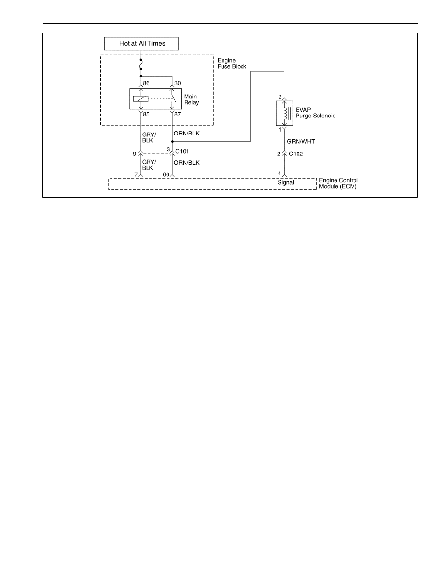
1F – 214 ENGINE CONTROLS
DAEWOO M-150 BL2
MAA1F240
DIAGNOSTIC TROUBLE CODE (DTC) – P0445 EVAP PURGE CONTROL
CIRCUIT FAULT
Circuit Description
The evaporative emission (EVAP) system includes the
following components :
D
Fuel tank.
D
EVAP vent solenoid.
D
Fuel tank pressure sensor.
D
Fuel pipes and hoses.
D
Fuel vapor lines.
D
Fuel cap.
D
EVAP canister.
D
Purge lines.
D
EVAP canister purge valve.
D
EVAP service port.
The evaporative emission system is checked by apply-
ing vacuum to the EVAP system and monitoring for a
vacuum decay. The engine control module(ECM) moni-
tors the vacuum level through the fuel tank pressure
sensor signal. At the appropriate time, the EVAP canis-
ter purge valve and the EVAP vent solenoid are turned
on, allowing the engine to draw a small vacuum on the
entire EVAP system. After the desired vacuum level has
been achieved, the EVAP canister purge valve is turned
OFF, sealing the system. If a sufficient vacuum level
cannot be achieved, a large leak is indicated. This can
be caused by the following conditions :
Missing or faulty fuel cap.
Disconnected or faulty fuel tank pressure sensor.
Disconnected, damaged, pinched, or blocked EVAP
purge line.
Disconnected or faulty EVAP canister purge valve.
Disconnected or faulty EVAP vent solenoid.
Open ignition feed circuit to the EVAP vent or purge so-
lenoid.
Damaged EVAP canister.
Leaking fuel sensor assembly O-ring.
Leaking fuel tank or fuel filler beck.
Any of the above conditions can set DTC P0445.
The test is failed if the tank vacuum is less than 10 in
H20 for 15 seconds and the manifold vacuum integral is
greater than 49512 (proportional to purge mass from the
tank).
Conditions for Setting the DTC
D
Intake Air Temperature(IAT) is between 4
°
C and
34
°
C(39
°
F and 93
°
F).at engine start up.
D
Engine Coolant Temperature(ECT) is between 4
°
C
and 34
°
C(39
°
F and 93
°
F).at engine start up.
D
Barometric pressure (BARO) is greater than 68kPA.
D
IAT is not more than 8
°
C(46
°
F) greater than the ECT
at start up.
D
Fuel level is between 10% and 90%.
D
The throttle position (TP) sensor is less than or equal
to 100%.
D
No fuel slosh, and the change in fuel level percent is
21 counts on 0.125 sec.
D
Manifold vacuum is greater than or equal to 10kPA.
D
Fuel level or change in tank pressure is less than or
equal to 24.9 in H2O.
D
System voltage is between 11V and 16V.

ENGINE CONTROLS 1F – 215
DAEWOO M-150 BL2
D
The EVAP system in unable to achieve or maintain
vacuum during the diagnostic test. The amount of
decay will vary within the fuel level.
Action Taken When the DTC Sets
D
The Malfunction Indicator Lamp (MIL) will illuminate.
D
The ECM will record operating conditions at the time
the diagnostic fails. This information will be stored in
the Freeze Frame and Failure Records buffers.
D
A history DTC is stored.
D
Coolant fan turns ON.
Conditions for Clearing the MIL/DTC
D
The MIL will turn off after four consecutive ignition
cycles in which the diagnostic runs without a fault.
D
A history DTC will clear after 40 consecutive warm-up
cycles without a fault.
D
DTC(s) can be cleared by using the scan tool.
Diagnostic Aids
Although this DTC is considered a type. A diagnostic, it
acts like a type B diagnostic under certain conditions.
Whenever this diagnostic reports the system has
passed, or if the battery is disconnected, the diagnostic
must fail twice before setting a DTC. The initial failure is
not reported to the diagnostic executive or displayed on
a scan tool. A passing system always reports to the
diagnostic executive immediately.
Check for the following conditions :
Missing or damaged fuel cap.
Missing or damaged O-rings at fuel vapor and EVAP
purge line canister fittings.
Cracked or punctured EVAP canister.
Damaged source vacuum line, EVAP purge line, EVAP
vent hose or fuel tank vapor line.
Poor connection at the ECM. Inspect the harness con-
nectors for the following conditions.
D
Backed-out terminals.
D
Improper mating.
D
Broken locks.
D
Improperly formed.
D
Damaged terminals.
D
Poor terminal-to-wire connection.
D
Damaged harness. Inspect the wiring harness to the
EVAP vent solenoid, EVAP canister purge valve, and
the fuel tank pressure sensor for an intermittent open
or short circuit.
D
Kinked, pinched or plugged vacuum source, EVAP
purge, or fuel tank vapor line. Verify that the lines are
not restricted.
DTC P0445 – EVAP Purge Control Circuit Fault
Step
Action
Value(s)
Yes
No
1
Perform an Euro On-Board Diagnostic (EOBD)
System Check.
Is the system check complete?
–
Go to Step 2
Go to
“On-Board
Diagnostic
System Check”
2
1. Disconnect the evaporative emission (EVAP)
canister purge valve connector.
2. Measure the resistance of the EVAP canister
purge valve connector.
Does the resistance measure near within the value
specified?
30
Ω
Go to Step 3
Go to Step 9
3
Connect a test light between EVAP canister purge
valve connector terminal 2 and ground.
Is the test light ON?
–
Go to Step 4
Go to Step 6
4
1. Disconnect the ECM connector.
2. Connect a test light between the ECM connector
terminal 66 and ground.
Is the test light ON?
–
Go to Step 5
Go to Step 7

1F – 216 ENGINE CONTROLS
DAEWOO M-150 BL2
DTC P0445 – EVAP Purge Control Circuit Fault (Cont’d)
Step
Action
Value(s)
Yes
No
5
1. Repair the high voltage or ground in the wire
between the EVAP canister purge valve
connector terminal 1 and the ECM connector
terminal 66.
2. Clear any Diagnostic Trouble Codes (DTCs) from
the ECM.
3. Perform the diagnostic system check.
Is the repair complete?
–
System OK
–
6
1. Disconnect the EVAP canister purge valve
connector.
2. Connect a test light between the EVAP canister
purge valve connector terminal 2 and battery.
Is the test light ON?
–
Go to Step 7
Go to Step 9
7
1. Disconnect the ECM connector.
2. Connect a test light between the ECM connector
terminal 65 and ground.
Is the test light ON?
–
Go to Step 8
Go to Step 10
8
1. Repair the low voltage in the wire between the
EVAP canister purge valve connector terminal 1
and the ECM connector terminal 66.
2. Clear any Diagnostic Trouble Codes (DTCs) from
the ECM.
3. Perform the diagnostic system check.
Is the repair complete?
–
System OK
–
9
1. Replace the EVAP canister purge valve.
2. Clear any Diagnostic Trouble Codes (DTCs) from
the ECM.
3. Perform the diagnostic system check.
Is the repair complete?
–
Go to Step 10
–
10
1. Using the scan tool, clear the Diagnostic Trouble
Codes (DTCs).
2. Start the engine and idle at normal operating
temperature.
3. Operate the vehicle within the conditions for
setting the DTC as specifiec in the supporting
text.
Does the scan tool indicate that this diagnostic ran
and passed?
–
Go to Step 11
Go to Step 2
11
Check if any additional DTCs are set.
Are any DTCs displayed that have not been
diagnosed?
–
Go to
Applicable DTC
table
System OK

ENGINE CONTROLS 1F – 217
DAEWOO M-150 BL2
BLANK
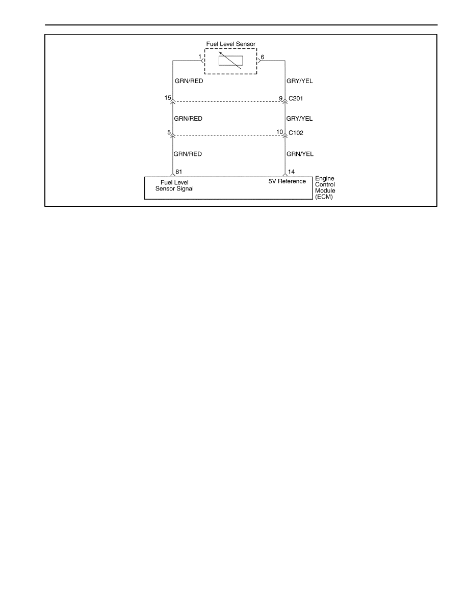
1F – 218 ENGINE CONTROLS
DAEWOO M-150 BL2
MAA1F250
DIAGNOSTIC TROUBLE CODE (DTC) – P0462 FUEL LEVEL SENSOR LOW
VOLTAGE
Circuit Description
The engine control module(ECM) uses the fuel level in-
put from the Fuel Level Sensor to calculate expected va-
por pressures within the fuel system. Vapor pressure
vary as the fuel level changes. Vapor pressure is critical
in determining if the evaporative emission (EVAP) sys-
tem is operating properly. Fuel Level is also used to de-
termine if the Fuel level is too high or too low to be able
to accurately detect EVAP system faults. This Diagnos-
tic Trouble Code(DTC) detects a stuck fuel level sender.
Conditions for Setting the DTC
D
Fuel Level Sensor voltage is less than 0.05V.
D
Fuel Level Sensor circuit low voltage.
Action Taken When The DTCs Sets
D
The Malfunction Indicator Lamp (MIL) will not illumi-
nate.
D
The ECM will store conditions which were present
when the DTC was set as Failure Records data only.
D
This information will not be stored in the Freeze
Frame data.
Conditions for Clearing the MIL/DTC
D
A history DTC will clear after 40 consecutive warm-up
cycles without a fault.
D
DTC(s) can be cleared by using the scan tool.
Diagnostic Aids
Inspect harness connectors for backed-out terminal, im-
proper mating, broken locks, improperly formed or dam-
aged terminals, and poor terminal-to-wire connection.
Inspect the wiring harness for damage.
A stuck Fuel Level Sensor may cause the DTC to set. If
DTC P0463 cannot be duplicated, the information in-
cluded in the Freeze Frame data can be useful in deter-
mining vehicle operating conditions when the DTC was
first set.
Resistance check for the Fuel Level Sensor.
Empty = 100 ohms or over.
Half full = about 32.5 ohms.
Full = 10 ohms or less.

ENGINE CONTROLS 1F – 219
DAEWOO M-150 BL2
DTC P0462 – Fuel Level Sensor Low Voltage
Step
Action
Value(s)
Yes
No
1
Perform an Euro On-Board Diagnostic (EOBD)
System Check.
Is the system check complete?
–
Go to Step 2
Go to
“On-Board
Diagnostic
System Check”
2
1. Turn the ignition switch to ON.
2. Install a scan tool.
3. Operate the vehicle within Freeze Frame
conditions as noted.
Is the Diagnostic Trouble Code (DTC) P0462 set?
–
Go to Step 3
Go to
“Diagnostic
Aids”
3
1. Disconnect the fuel sender electircal connector
from the fuel pump.
2. Using a digital voltmeter (DVM), measure the
voltage in the signal circuit at terminal 1.
Is the voltage within the specified value?
0.2–4.8V
Go to Step 4
Go to Step 6
4
Check for a proper ground connection at the fuel
tank and repair as necessary.
Is a repair necessary?
–
Go to Step 11
Go to Step 5
5
1. Remove the fuel sender from the fuel tank.
2. Reconnect the fuel sender electrical connector.
3. Monitor the Fuel Level Sensor parameter on the
scan tool while moving the Fuel Level Sensor
float from the empty position to the full position.
4. Repeat the procedure several times.
Does the Fuel Level Sensor value on the scan tool
increase and then decrease steadily when the float
is moved?
–
Go to
“Diagnostic
Aids”
Go to Step 8
6
Check for an open or short to ground in the Fuel
Level Sensor circuit and repair as necessary.
Is the repair necessary?
–
Go to Step 11
Go to Step 9
7
Repair the open or short to ground in the Fuel Level
Sensor circuit between the Fuel Level Sensor
harness connector and the Fuel Level Sensor.
Is the repair complete?
–
Go to Step 11
–
8
Replace the fuel sender assembly.
Is the replacement complete?
–
Go to Step 11
–
9
1. Connect the fuel sender electrical connector.
2. Disconnect the engine control module(ECM)
connector.
3. Using a digital voltmeter (DVM) measure the
voltage in the signal circuit, at terminal 81.
Does the DVM read within the specified value?
0.2–4.8V
Go to Step 10
Go to
section 9E,
Instrumenta-
tion/Driver
Information
10
Replace the ECM.
Is the repair complete?
–
Go to Step 11
–
11
1. Using the scan tool, clear the Diagnostic Trouble
Codes (DTCs).
2. Start the engine and idle at normal operating
temperature.
3. Operate the vehicle within the conditions for
setting the DTC as specifiec in the supporting
text.
Does the scan tool indicate that this diagnostic ran
and passed?
–
Go to Step 12
Go to Step 2

1F – 220 ENGINE CONTROLS
DAEWOO M-150 BL2
DTC P0462 – Fuel Level Sensor Low Voltage (Cont’d)
Step
Action
Value(s)
Yes
No
12
Check if any additional DTCs are set.
Are any DTCs displayed that have not been
diagnosed?
–
Go to
Applicable DTC
table
System OK

ENGINE CONTROLS 1F – 221
DAEWOO M-150 BL2
BLANK

1F – 222 ENGINE CONTROLS
DAEWOO M-150 BL2
MAA1F250
DIAGNOSTIC TROUBLE CODE (DTC) – P0463 FUEL LEVEL SENSOR HIGH
VOLTAGE
Circuit Description
The engine control module(ECM) uses the fuel level in-
put from the Fuel Level Sensor to calculate expected va-
por pressures within the fuel system. Vapor pressure
vary as the fuel level changes. Vapor pressure is critical
in determining if the evaporative emission (EVAP) sys-
tem is operating properly. Fuel Level is also used to de-
termine if the Fuel level is too high or too low to be able
to accurately detect EVAP system faults. This Diagnos-
tic Trouble Code(DTC) detects a stuck fuel level sender.
Conditions for Setting the DTC
D
Fuel Level Sensor voltage is higher than 4.9V.
D
Fuel Level Sensor circuit high voltage.
Action Taken When the DTC Sets
D
The Malfunction Indicator Lamp (MIL) will not illumi-
nate.
D
The ECM will store conditions which were present
when the DTC was set as Failure Records data only.
D
This information will not be stored in the Freeze
Frame data.
Conditions for Clearing the MIL/DTC
D
A history DTC will clear after 40 consecutive warm-up
cycles without a fault.
D
DTC(s) can be cleared by using the scan tool.
Diagnostic Aids
Inspect harness connectors for backed-out terminal, im-
proper mating, broken locks, improperly formed or dam-
aged terminals, and poor terminal-to-wire connection.
Inspect the wiring harness for damage.
A stuck Fuel Level Sensor may cause the DTC to set. If
DTC P0463 cannot be duplicated, the information in-
cluded in the Freeze Frame data can be useful in deter-
mining vehicle operating conditions when the DTC was
first set.
Resistance check for the Fuel Level Sensor.
Empty = 100 ohms or over.
Half full = about 32.5 ohms.
Full = 10 ohms or less.

ENGINE CONTROLS 1F – 223
DAEWOO M-150 BL2
DTC P0463 – Fuel Level Sensor High Voltage
Step
Action
Value(s)
Yes
No
1
Perform an Euro On-Board Diagnostic (EOBD)
System Check.
Is the system check complete?
–
Go to Step 2
Go to
“On-Board
Diagnostic
System Check”
2
1. Turn the ignition switch to ON.
2. Install a scan tool.
3. Operate the vehicle within Freeze Frame
conditions as noted.
Is the Diagnostic Trouble Code (DTC) P0463 set?
–
Go to Step 3
Go to
“Diagnostic
Aids”
3
1. Disconnect the fuel sender electrical connector
from the fuel pump.
2. Using a digital voltmeter (DVM), measure the
voltage in the signal circuit at terminal 1.
Is the voltage within the specified value?
0.2–4.9V
Go to Step 4
Go to Step 6
4
Check for a proper ground connection at the fuel
tank and repair as necessary.
Is a repair necessary?
–
Go to Step 11
Go to Step 5
5
1. Remove the fuel sender from the fuel tank.
2. Reconnect the fuel pump electrical connector.
3. Monitor the Fuel Level Sensor parameter on the
scan tool while moving the Fuel Level Sensor
float from the empty position to the full position.
4. Repeat the procedure several times.
Does the Fuel Level Sensor value on the scan tool
increase and then decrease steadily when the float
is moved?
–
Go to
“Diagnostic
Aids”
Go to Step 8
6
Check for an open or short to battery voltage in the
Fuel Level Sensor circuit and repair as necessary.
Is the repair necessary?
–
Go to Step 11
Go to Step 9
7
Repair the open or short to battery voltage in the
Fuel Level Sensor circuit between the Fuel Level
Sensor harness connector and the Fuel Level
Sensor.
Is the repair complete?
–
Go to Step 11
–
8
Replace the fuel sender assembly.
Is the replacement complete?
–
Go to Step 11
–
9
1. Connect the fuel pump electrical connector.
2. Disconnect the engine control module(ECM)
connector.
3. Using a digital voltmeter (DVM) measure the
voltage in the signal circuit, at terminal 81.
Does the DVM read within the specified value?
0.2–4.9V
Go to Step 10
Go to
section 9E,
Instrumenta-
tion/Driver
Information
10
Replace the ECM.
Is the repair complete?
–
Go to Step 11
–
11
1. Using the scan tool, clear the Diagnostic Trouble
Codes (DTCs).
2. Start the engine and idle at normal operating
temperature.
3. Operate the vehicle within the conditions for
setting the DTC as specifiec in the supporting
text.
Does the scan tool indicate that this diagnostic ran
and passed?
–
Go to Step 12
Go to Step 2

1F – 224 ENGINE CONTROLS
DAEWOO M-150 BL2
DTC P0463 – Fuel Level Sensor High Voltage (Cont’d)
Step
Action
Value(s)
Yes
No
12
Check if any additional DTCs are set.
Are any DTCs displayed that have not been
diagnosed?
–
Go to
Applicable DTC
table
System OK

ENGINE CONTROLS 1F – 225
DAEWOO M-150 BL2
BLANK

1F – 226 ENGINE CONTROLS
DAEWOO M-150 BL2
MAA1F090
DIAGNOSTIC TROUBLE CODE (DTC) – P0480 LOW SPEED COOLING FAN
RELAY CIRCUIT FAULT (WITHOUT A/C)
Circuit Description
Ignition voltage is supplied directly to the cooling fan
relay coil. The engine control module(ECM) controls the
relay by grounding the control circuit via an internal
switch called a driver. The primary function of the driver
is supply the ground for the component being controlled.
Each driver has a fault line which is monitored by the
ECM. When the ECM is commanding a component ON,
the voltage of the control circuit should be low (near
0volts). When the ECM is commanding the control cir-
cuit to a component OFF, the voltage potential of the cir-
cuit should be high(near battery voltage). If the fault
detection circuit senses a voltage other than what is ex-
pected, the fault line status will change causing the DTC
to set.
The relay is used to control the high current flow to the
cooling fan motors. This allows the ECM driver to only
have to handle the relatively low current used by the
relay.
Conditions for Setting the DTC
D
Diagnostic Trouble Codes (DTCs) P0117, P0118 not
set.
D
Ignition ON.
D
Ignition voltage is greater than 10 volts.
D
Engine run time is greater than 5 seconds.
Action Taken When the DTC Sets
D
The Malfunction Indicator Lamp (MIL) will not illumi-
nate.
D
The ECM will store conditions which were present
when the DTC was set as Failure Records data only.
D
This information will not be stored in the Freeze
Frame data.
Conditions for Clearing the MIL/DTC
D
A history DTC will clear after 40 consecutive warm-up
cycles without a fault.
D
DTC(s) can be cleared by using the scan tool.
Diagnostic Aids
Using Freeze Frame and/or failure records data may aid
in locating an intermittent condition. If the DTC cannot
be duplicated, the information included in the Freeze
Frame and/or failure records data can be useful in deter-
mining how many miles since the DTC set. The fail
counter and Pass Counter can also be used to deter-
mine how many ignition cycles the diagnostics reported

ENGINE CONTROLS 1F – 227
DAEWOO M-150 BL2
a Freeze Frame conditions (rpm, load, vehicle speed,
temperature, etc.) that .are noted. This will isolate when
the DTC failed.
DTC P0480 – Low Speed Cooling Fan Relay Circuit Fault (WITHOUT A/C)
Step
Action
Value(s)
Yes
No
1
Perform an Euro On-Board Diagnostic (EOBD)
System Check.
Is the system check complete?
–
Go to Step 2
Go to
“On-Board
Diagnostic
System Check”
2
1. Turn the ignition switch to ON with the engine
OFF.
2. Install a scan tool.
3. Command the relay ON and OFF.
Does the relay turn ON and OFF when
commanded?
–
Go to Step 3
Go to Step 5
3
1. Turn the ignition switch to LOCK.
2. Disconnect the engine control module (ECM)
connector.
3. Turn the ignition switch to ON.
4. Using a digital voltmeter(DVM), measure the
current in low speed relay control circuit, at
terminal 39 to ground for 2 minutes.
Does the amperage measure less than the specified
value?
0.75 amps
Go to
“Diagnostic
Aids”
Go to Step 4
4
1. Turn the ignition switch to LOCK.
2. Disconnect the relay.
3. Using a DVM, measure the resistance between
terminals 87 and 39 in the relay control circuit in
the ECM harness connector to ground.
Does the DVM display infinite resistance?
–
Go to Step 12
Go to Step 10
5
1. Turn the ignition switch to LOCK.
2. Disconnect the relay.
3. Connect a test light between the relay coil
terminals 30 and 87 in the relay harness
connector.
4. Turn the Turn the ignition switch to ON.
5. Using the scan tool, command the relay ON and
OFF.
Does the test light turn ON and OFF with each
commanded?
–
Go to Step 8
Go to Step 6
6
With the test light connected to ground, probe the
ignition feed circuit in the relay harness connector.
Does the test light illuminate?
–
Go to Step 7
Go to Step 11
7
1. Turn the ignition switch to LOCK.
2. Reconnect the relay.
3. Disconnect the ECM connector containing the
relay control circuit.
4. Turn the Turn the ignition switch to ON.
5. With a fused jumper wire connected to ground,
probe the relay control circuit at terminal 39 in the
ECM harness connector.
Does the relay operate?
–
Go to Step 9
Go to Step 10
8
Check the connections at the relay.
Is a problem found and corrected?
–
Go to Step 14
Go to Step 12

1F – 228 ENGINE CONTROLS
DAEWOO M-150 BL2
DTC P0480 – Low Speed Cooling Fan Relay Circuit Fault (WITHOUT A/C) (Cont’d)
Step
Action
Value(s)
Yes
No
9
Check the connection at the ECM.
Is a problem found and corrected?
–
Go to Step 11
Go to Step 13
10
Repair the faulty relay control circuit.
Is the repair complete?
–
Go to Step 14
–
11
Repair the faulty relay ignition feed circuit.
Is the repair complete?
–
Go to Step 14
–
12
Replace the relay.
Is the replacement complete?
–
Go to Step 14
–
13
Replace the ECM.
Is the replacement complete?
–
Go to Step 14
–
14
1. Using the scan tool, clear the Diagnostic Trouble
Codes (DTCs).
2. Start the engine and idle at normal operating
temperature.
3. Operate the vehicle within the conditions for
setting the DTC as specifiec in the supporting
text.
Does the scan tool indicate that this diagnostic ran
and passed?
–
Go to Step 15
Go to Step 2
15
Check if any additional DTCs are set.
Are any DTCs displayed that have not been
diagnosed?
–
Go to
Applicable DTC
table
System OK

ENGINE CONTROLS 1F – 229
DAEWOO M-150 BL2
BLANK

1F – 230 ENGINE CONTROLS
DAEWOO M-150 BL2
MAA1F270
DIAGNOSTIC TROUBLE CODE (DTC) – P0480 LOW SPEED COOLING FAN
RELAY CIRCUIT FAULT (WITH A/C)
Circuit Description
Ignition voltage is supplied directly to the cooling fan
relay coil. The engine control module(ECM) controls the
relay by grounding the control circuit via an internal
switch called a driver. The primary function of the driver
is supply the ground for the component being controlled.
Each driver has a fault line which is monitored by the
ECM. When the ECM is commanding a component ON,
the voltage of the control circuit should be low (near
0volts). When the ECM is commanding the control cir-
cuit to a component OFF, the voltage potential of the cir-
cuit should be high(near battery voltage). If the fault
detection circuit senses a voltage other than what is ex-
pected, the fault line status will change causing the DTC
to set.
The relay is used to control the high current flow to the
cooling fan motors. This allows the ECM driver to only
have to handle the relatively low current used by the
relay.
Conditions for Setting the DTC
D
Diagnostic Trouble Codes (DTCs) P0117, P0118 not
set.
D
Ignition ON.
D
Ignition voltage is greater than 10 volts.
D
Engine run time is greater than 5 seconds.
Action Taken When The DTCs Sets
D
The Malfunction Indicator Lamp (MIL) will not illumi-
nate.
D
The ECM will store conditions which were present
when the DTC was set as Failure Records data only.
D
This information will not be stored in the Freeze
Frame data.
Conditions for Clearing the MIL/DTC
D
A history DTC will clear after 40 consecutive warm-up
cycles without a fault.
D
DTC(s) can be cleared by using the scan tool.
Diagnostic Aids
Using Freeze Frame and/or failure records data may aid
in locating an intermittent condition. If the DTC cannot
be duplicated, the information included in the Freeze
Frame and/or failure records data can be useful in deter-
mining how many miles since the DTC set. The fail
counter and Pass Counter can also be used to deter-
mine how many ignition cycles the diagnostics reported

ENGINE CONTROLS 1F – 231
DAEWOO M-150 BL2
a Freeze Frame conditions (rpm, load, vehicle speed,
temperature, etc.) that .are noted. This will isolate when
the DTC failed.
DTC P0480 – Low Speed Cooling Fan Relay Circuit Fault (with A/C)
Step
Action
Value(s)
Yes
No
1
Perform an Euro On-Board Diagnostic (EOBD)
System Check.
Is the system check complete?
–
Go to Step 2
Go to
“On-Board
Diagnostic
System Check”
2
1. Turn the ignition switch to ON with the engine
OFF.
2. Install a scan tool.
3. Command the relay ON and OFF.
Does the relay turn ON and OFF when
commanded?
–
Go to Step 3
Go to Step 5
3
1. Turn the ignition switch to LOCK.
2. Disconnect the engine control module (ECM)
connector.
3. Turn the ignition switch to ON.
4. Using a digital voltmeter(DVM), measure the
current in low speed relay control circuit, at
terminal 10 to ground for 2 minutes.
Does the amperage measure less than the specified
value?
0.75 amps
Go to
“Diagnostic
Aids”
Go to Step 4
4
1. Turn the ignition switch to LOCK.
2. Disconnect the relay.
3. Using a DVM, measure the resistance between
terminals 85 and 5 in the relay control circuit in
the ECM harness connector to ground.
Does the DVM display infinite resistance?
–
Go to Step 12
Go to Step 10
5
1. Turn the ignition switch to LOCK.
2. Disconnect the relay.
3. Connect a test light between the relay coil
terminals 86 and 85 in the relay harness
connector.
4. Turn the Turn the ignition switch to ON.
5. Using the scan tool, command the relay ON and
OFF.
Does the test light turn ON and OFF with each
commanded?
–
Go to Step 8
Go to Step 6
6
With the test light connected to ground, probe the
ignition feed circuit in the relay harness connector.
Does the test light illuminate?
–
Go to Step 7
Go to Step 11
7
1. Turn the ignition switch to LOCK.
2. Reconnect the relay.
3. Disconnect the ECM connector containing the
relay control circuit.
4. Turn the Turn the ignition switch to ON.
5. With a fused jumper wire connected to ground,
probe the relay control circuit at terminal 5 in the
ECM harness connector.
Does the relay operate?
–
Go to Step 9
Go to Step 10
8
Check the connections at the relay.
Is a problem found and corrected?
–
Go to Step 14
Go to Step 12

1F – 232 ENGINE CONTROLS
DAEWOO M-150 BL2
DTC P0480 – Low Speed Cooling Fan Relay Circuit Fault (with A/C) (Cont’d)
Step
Action
Value(s)
Yes
No
9
Check the connection at the ECM.
Is a problem found and corrected?
–
Go to Step 11
Go to Step 13
10
Repair the faulty relay control circuit.
Is the repair complete?
–
Go to Step 14
–
11
Repair the faulty relay ignition feed circuit.
Is the repair complete?
–
Go to Step 14
–
12
Replace the relay.
Is the replacement complete?
–
Go to Step 14
–
13
Replace the ECM.
Is the replacement complete?
–
Go to Step 14
–
14
1. Using the scan tool, clear the Diagnostic Trouble
Codes (DTCs).
2. Start the engine and idle at normal operating
temperature.
3. Operate the vehicle within the conditions for
setting the DTC as specifiec in the supporting
text.
Does the scan tool indicate that this diagnostic ran
and passed?
–
Go to Step 15
Go to Step 2
15
Check if any additional DTCs are set.
Are any DTCs displayed that have not been
diagnosed?
–
Go to
Applicable DTC
table
System OK

ENGINE CONTROLS 1F – 233
DAEWOO M-150 BL2
BLANK
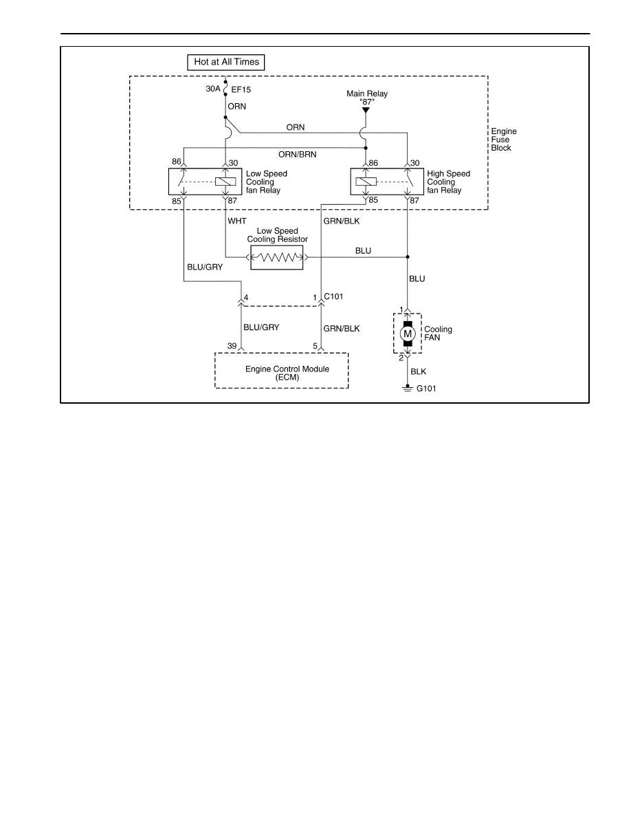
1F – 234 ENGINE CONTROLS
DAEWOO M-150 BL2
MAA1F090
DIAGNOSTIC TROUBLE CODE (DTC) – P0481 HIGH SPEED COOLING FAN
RELAY CIRCUIT FAULT (WITHOUT A/C)
Circuit Description
Ignition voltage is supplied directly to the cooling fan
relay coil. The engine control module(ECM) controls the
relay by grounding the control circuit via an internal
switch called a driver. The primary function of the driver
is supply the ground for the component being controlled.
Each driver has a fault line which is monitored by the
ECM. When the ECM is commanding a component ON,
the voltage of the control circuit should be low (near
0volts). When the ECM is commanding the control cir-
cuit to a component OFF, the voltage potential of the cir-
cuit should be high(near battery voltage). If the fault
detection circuit senses a voltage other than what is ex-
pected, the fault line status will change causing the DTC
to set.
The relay is used to control the high current flow to the
cooling fan motors. This allows the ECM driver to only
have to handle the relatively low current used by the
relay.
Conditions for Setting the DTC
D
Diagnostic Trouble Codes (DTCs) P0117, P0118 not
set.
D
Ignition ON.
D
Ignition voltage is greater than 10 volts.
D
Engine run time is greater than 5 seconds.
Action Taken When The DTCs Sets
D
The Malfunction Indicator Lamp (MIL) will not illumi-
nate.
D
The ECM will store conditions which were present
when the DTC was set as Failure Records data only.
D
This information will not be stored in the Freeze
Frame data.
Conditions for Clearing the MIL/DTC
D
A history DTC will clear after 40 consecutive warm-up
cycles without a fault.
D
DTC(s) can be cleared by using the scan tool.
Diagnostic Aids
Using Freeze Frame and/or failure records data may aid
in locating an intermittent condition. If the DTC cannot
be duplicated, the information included in the Freeze
Frame and/or failure records data can be useful in deter-
mining how many miles since the DTC set. The fail
counter and Pass Counter can also be used to deter-
mine how many ignition cycles the diagnostics reported

ENGINE CONTROLS 1F – 235
DAEWOO M-150 BL2
a Freeze Frame conditions (rpm, load, vehicle speed,
temperature, etc.) that .are noted. This will isolate when
the DTC failed.
DTC P0481 – High Speed Cooling Fan Relay Circuit Fault (without A/C)
Step
Action
Value(s)
Yes
No
1
Perform an Euro On-Board Diagnostic (EOBD)
System Check.
Is the system check complete?
–
Go to Step 2
Go to
“On-Board
Diagnostic
System Check”
2
1. Turn the ignition switch to ON with the engine
OFF.
2. Install a scan tool.
3. Command the relay ON and OFF.
Does the relay turn ON and OFF when
commanded?
–
Go to Step 3
Go to Step 5
3
1. Turn the ignition switch to LOCK.
2. Disconnect the engine control module (ECM)
connector.
3. Turn the ignition switch to ON.
4. Using a digital voltmeter(DVM), measure the
current in high speed relay control circuit, at
terminal 5 to ground for 2 minutes.
Does the amperage measure less than the specified
value?
0.75 amps
Go to
“Diagnostic
Aids”
Go to Step 4
4
1. Turn the ignition switch to LOCK.
2. Disconnect the relay.
3. Using a DVM, measure the resistance between
terminals 85 and 5 in the relay control circuit in
the ECM harness connector to ground.
Does the DVM display infinite resistance?
–
Go to Step 12
Go to Step 10
5
1. Turn the ignition switch to LOCK.
2. Disconnect the relay.
3. Connect a test light between the relay coil
terminals 86 and 85 in the relay harness
connector.
4. Turn the Turn the ignition switch to ON.
5. Using the scan tool, command the relay ON and
OFF.
Does the test light turn ON and OFF with each
commanded?
–
Go to Step 8
Go to Step 6
6
With the test light connected to ground, probe the
ignition feed circuit in the relay harness connector.
Does the test light illuminate?
–
Go to Step 7
Go to Step 11
7
1. Turn the ignition switch to LOCK.
2. Reconnect the relay.
3. Disconnect the ECM connector containing the
relay control circuit.
4. Turn the Turn the ignition switch to ON.
5. With a fused jumper wire connected to ground,
probe the relay control circuit at terminal 5 in the
ECM harness connector.
Does the relay operate?
–
Go to Step 9
Go to Step 10
8
Check the connections at the relay.
Is a problem found and corrected?
–
Go to Step 14
Go to Step 12

1F – 236 ENGINE CONTROLS
DAEWOO M-150 BL2
DTC P0481 – High Speed Cooling Fan Relay Circuit Fault (without A/C) (Cont’d)
Step
Action
Value(s)
Yes
No
9
Check the connection at the ECM.
Is a problem found and corrected?
–
Go to Step 11
Go to Step 13
10
Repair the faulty relay control circuit.
Is the repair complete?
–
Go to Step 14
–
11
Repair the faulty relay ignition feed circuit.
Is the repair complete?
–
Go to Step 14
–
12
Replace the relay.
Is the replacement complete?
–
Go to Step 14
–
13
Replace the ECM.
Is the replacement complete?
–
Go to Step 14
–
14
1. Using the scan tool, clear the Diagnostic Trouble
Codes (DTCs).
2. Start the engine and idle at normal operating
temperature.
3. Operate the vehicle within the conditions for
setting the DTC as specifiec in the supporting
text.
Does the scan tool indicate that this diagnostic ran
and passed?
–
Go to Step 15
Go to Step 2
15
Check if any additional DTCs are set.
Are any DTCs displayed that have not been
diagnosed?
–
Go to
Applicable DTC
table
System OK

ENGINE CONTROLS 1F – 237
DAEWOO M-150 BL2
BLANK
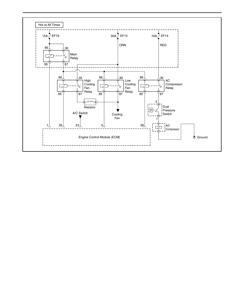
1F – 238 ENGINE CONTROLS
DAEWOO M-150 BL2
MAA1F270
DIAGNOSTIC TROUBLE CODE (DTC) – P0481 HIGH SPEED COOLING FAN
RELAY CIRCUIT FAULT (WITH A/C)
Circuit Description
Ignition voltage is supplied directly to the cooling fan
relay coil. The engine control module(ECM) controls the
relay by grounding the control circuit via an internal
switch called a driver. The primary function of the driver
is supply the ground for the component being controlled.
Each driver has a fault line which is monitored by the
ECM. When the ECM is commanding a component ON,
the voltage of the control circuit should be low (near
0volts). When the ECM is commanding the control cir-
cuit to a component OFF, the voltage potential of the cir-
cuit should be high(near battery voltage). If the fault
detection circuit senses a voltage other than what is ex-
pected, the fault line status will change causing the DTC
to set.
The relay is used to control the high current flow to the
cooling fan motors. This allows the ECM driver to only
have to handle the relatively low current used by the
relay.
Conditions for Setting the DTC
D
Diagnostic Trouble Codes (DTCs) P0117, P0118 not
set.
D
Ignition ON.
D
Ignition voltage is greater than 10 volts.
D
Engine run time is greater than 5 seconds.
Action Taken When The DTCs Sets
D
The Malfunction Indicator Lamp (MIL) will not illumi-
nate.
D
The ECM will store conditions which were present
when the DTC was set as Failure Records data only.
D
This information will not be stored in the Freeze
Frame data.
Conditions for Clearing the MIL/DTC
D
A history DTC will clear after 40 consecutive warm-up
cycles without a fault.
D
DTC(s) can be cleared by using the scan tool.
Diagnostic Aids
Using Freeze Frame and/or failure records data may aid
in locating an intermittent condition. If the DTC cannot
be duplicated, the information included in the Freeze
Frame and/or failure records data can be useful in deter-
mining how many miles since the DTC set. The fail
counter and Pass Counter can also be used to deter-
mine how many ignition cycles the diagnostics reported

ENGINE CONTROLS 1F – 239
DAEWOO M-150 BL2
a Freeze Frame conditions (rpm, load, vehicle speed,
temperature, etc.) that .are noted. This will isolate when
the DTC failed.
DTC P0481 – High Speed Cooling Fan Relay Circuit Fault (with A/C)
Step
Action
Value(s)
Yes
No
1
Perform an Euro On-Board Diagnostic (EOBD)
System Check.
Is the system check complete?
–
Go to Step 2
Go to
“On-Board
Diagnostic
System Check”
2
1. Turn the ignition switch to ON with the engine
OFF.
2. Install a scan tool.
3. Command the relay ON and OFF.
Does the relay turn ON and OFF when
commanded?
–
Go to Step 3
Go to Step 5
3
1. Turn the ignition switch to LOCK.
2. Disconnect the engine control module (ECM)
connector.
3. Turn the ignition switch to ON.
4. Using a digital voltmeter(DVM), measure the
current in high speed relay control circuit, at
terminal 39 to ground for 2 minutes.
Does the amperage measure less than the specified
value?
0.75 amps
Go to
“Diagnostic
Aids”
Go to Step 4
4
1. Turn the ignition switch to LOCK.
2. Disconnect the relay.
3. Using a DVM, measure the resistance between
terminals 85 and 39 in the high speed cooling fan
relay control circuit in the ECM harness connector
to ground.
Does the DVM display infinite resistance?
–
Go to Step 12
Go to Step 10
5
1. Turn the ignition switch to LOCK.
2. Disconnect the relay.
3. Connect a test light between the relay coil
terminals 86 and 85 in the relay harness
connector.
4. Turn the Turn the ignition switch to ON.
5. Using the scan tool, command the relay ON and
OFF.
Does the test light turn ON and OFF with each
commanded?
–
Go to Step 8
Go to Step 6
6
With the test light connected to ground, probe the
ignition feed circuit in the relay harness connector.
Does the test light illuminate?
–
Go to Step 7
Go to Step 11
7
1. Turn the ignition switch to LOCK.
2. Reconnect the relay.
3. Disconnect the ECM connector containing the
relay control circuit.
4. Turn the Turn the ignition switch to ON.
5. With a fused jumper wire connected to ground,
probe the relay control circuit at terminal 10 in the
ECM harness connector.
Does the relay operate?
–
Go to Step 9
Go to Step 10

1F – 240 ENGINE CONTROLS
DAEWOO M-150 BL2
DTC P0481 – High Speed Cooling Fan Relay Circuit Fault (with A/C) (Cont’d)
Step
Action
Value(s)
Yes
No
8
Check the connections at the relay.
Is a problem found and corrected?
–
Go to Step 14
Go to Step 12
9
Check the connection at the ECM.
Is a problem found and corrected?
–
Go to Step 11
Go to Step 13
10
Repair the faulty relay control circuit.
Is the repair complete?
–
Go to Step 14
–
11
Repair the faulty relay ignition feed circuit.
Is the repair complete?
–
Go to Step 14
–
12
Replace the relay.
Is the replacement complete?
–
Go to Step 14
–
13
Replace the ECM.
Is the replacement complete?
–
Go to Step 14
–
14
1. Using the scan tool, clear the Diagnostic Trouble
Codes (DTCs).
2. Start the engine and idle at normal operating
temperature.
3. Operate the vehicle within the conditions for
setting the DTC as specifiec in the supporting
text.
Does the scan tool indicate that this diagnostic ran
and passed?
–
Go to Step 15
Go to Step 2
15
Check if any additional DTCs are set.
Are any DTCs displayed that have not been
diagnosed?
–
Go to
Applicable DTC
table
System OK

ENGINE CONTROLS 1F – 241
DAEWOO M-150 BL2
BLANK
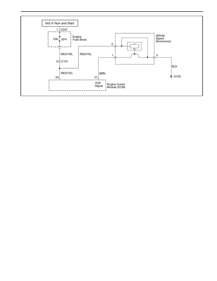
1F – 242 ENGINE CONTROLS
DAEWOO M-150 BL2
MAA1F280
DIAGNOSTIC TROUBLE CODE (DTC) – P0501 VEHICLE SPEED NO SIGNAL
(M/T ONLY)
Circuit Description
Vehicle speed information is provided to the engine con-
trol module (ECM) by the voltage speed sensor (VSS) is
a permanent magnet generator that is mounted in the
transaxle and produces a pulsing voltage whenever ve-
hicle speed is over 3 mph (5km/h). The A/C voltage level
and the number of pulses increase with vehicle speed.
The ECM converts the pulsing voltage into mph (km/h)
and than supplies the necessary signal to the instrument
panel for speedometer / odometer operation and to the
cruise control module and multi-function alarm module
operation. The Diagnostic Trouble Code (DTC) will de-
tect if vehicle speed is reasonable according to engine
rpm and load.
Conditions for Setting the DTC
D
Vehicle speed is not change at least 10 seconds.
D
Engine speed is greater than 2,100rpm.
D
MAF is greater than 152mg/tdc.
Action taken when The DTCs Sets
D
The Malfunction Indicator Lamp (MIL) will illuminate.
D
The ECM will record operating conditions at the time
the diagnostic fails. This information will be stored in
the Freeze Frame and failure records buffers.
D
A history DTC is stored.
Conditions for Clearing the MIL/DTC
D
The MIL will turn off after four consecutive ignition
cycles in which the diagnostic runs without a fault.
D
A history DTC will clear after 40 consecutive warm up
cycles without a fault.
D
Using the scan tool can clear DTC(s).
Diagnostic Aids
An Intermittent problem may be caused by a poor con-
nection, rubbed through wire insulation, or wire that is
broken inside the insulation.
VSS signal circuit should be thoroughly checked for the
following conditions
D
Backed-out terminals
D
Improper mating
D
Broken locks
D
Improperly formed
D
Damaged terminals
D
Poor terminals to wire connection
D
Physical damage to the wiring harness
Ensure the VSS is correctly torqued to the trnasaxle
housing.
Refer to “intermittents” in this Section.

ENGINE CONTROLS 1F – 243
DAEWOO M-150 BL2
DTC P0501 – Vehicle Speed No Signal(M/T Only)
Step
Action
Value(s)
Yes
No
1
Perform an Euro On-Board Diagnostic (EOBD) Sys-
tem Check.
Is the system check complete?
–
Go to Step 2
Go to
“On-Board
Diagnostic
System Check”
2
Notice: Running the vehicle in gear with the wheels
hanging down at full travel will damage the drive
axles.
1. Turn the ignition ON, with the engine OFF.
2. Install a scan tool.
3. Raise the drive wheels.
4. Support the lower control arms so that the drive
axles are in a horizontal (straight) position.
5. Allow the engine to idle in gear.
Does the scan tool display vehicle speed above the
specified value?
0 mph
Go to Step 3
Go to Step 4
3
1. Turn the ignition ON, with the engine OFF.
2. Review the Freeze Frame data and note the
parameters.
3. Operate the vehicle within the Freeze Frame
conditions and Conditions for Setting this DTC.
Does the scan tool display the vehicle speed above
the specified value?
0 mph
Go to Step 12
Go to Step 4
4
1. Turn the ignition OFF.
2. Disconnect the engine control module(ECM)
connector.
4. using a digital voltmeter(DVM) connected to
ground, measure the voltage in the Vehicle Speed
Sensor (VSS) signal circuit, at terminal 1 while
rotating the wheels.
Is the voltage greater than or eqaul to specified
value?
0.5 v
Go to Step 12
Go to Step 5
5
Measure the resistant in the VSS signal circuit while
rotating the wheels.
Is the resistance greater than the specified value?
1950
Ω
Go to Step 6
Go to Step 7
6
Check the VSS signal circuit for an open and repair
as necessary.
Is the repair complete?
–
Go to Step 12
Go to Step 9
7
Is the resistance value within or equal to the speci-
fied value?
1300–1950
Ω
Go to Step 8
Go to Step 9
8
Check the VSS signal circuit for a short to ground or
for being shorted together and repair as necessary.
Is a repair necessary?
–
Go to Step 12
Go to Step 12
9
1. Remove the VSS.
2. Measure the resistance between terminals 2 and
3.
Is the resistance value within the specified value?
1300–1950
Ω
Go to Step 11
Go to Step 10
10
Replace the VSS.
Is the action complete?
–
Go to Step 12
–
11
Replace the ECM.
Is the action complete?
–
Go to Step 12
–

1F – 244 ENGINE CONTROLS
DAEWOO M-150 BL2
DTC P0501 – Vehicle Speed No Signal(M/T Only) (Cont’d)
ÁÁÁÁ
ÁÁÁÁ
Step
ÁÁÁÁÁÁÁÁÁÁÁÁÁÁÁÁÁ
ÁÁÁÁÁÁÁÁÁÁÁÁÁÁÁÁÁ
Action
ÁÁÁÁÁ
ÁÁÁÁÁ
Value(s)
ÁÁÁÁÁÁÁ
ÁÁÁÁÁÁÁ
Yes
ÁÁÁÁÁÁ
ÁÁÁÁÁÁ
No
12
1. Using the scan tool, clear the Diagnostic Trouble
Codes (DTCs).
2. Start the engine and idle at normal operating
temperature.
3. Operate the vehicle within the conditions for
setting the DTC as specifiec in the supporting
text.
Does the scan tool indicate that this diagnostic ran
and passed?
–
Go to Step 15
Go to Step 2
13
Check if any additional DTCs are set.
Are any DTCs displayed that have not been
diagnosed?
–
Go to
Applicable DTC
table
System OK

ENGINE CONTROLS 1F – 245
DAEWOO M-150 BL2
BLANK
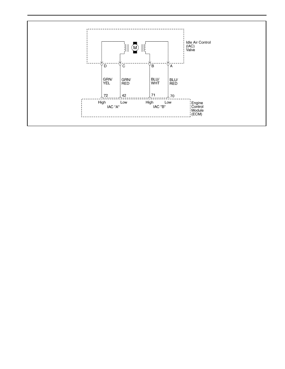
1F – 246 ENGINE CONTROLS
DAEWOO M-150 BL2
MAA1F070
DIAGNOSTIC TROUBLE CODE (DTC) 0505
IDLE AIR CONTROL VALVE (IACV) CIRCUIT FAULT
Circuit Description
The Engine Control Module (ECM) controls the air en-
tering into the engine with an Idle Air Control (IAC)
Valve. To increase the idle rpm, the ECM commands the
pintle inside the IAC valve away from the throttle body
seat. This allows more air to bypass through the throttle
blade. To decrease the rpm the ECM commands the
pintle towards the throttle body seat. This reduces the
amount of air bypassing the throttle blade. A scan tool
will read the IAC valve pintle position in counts. The
higher the counts, the more air that is allowed to bypass
the throttle blade. This Diagnostic Trouble Code (DTC)
determines if a low idle condition exists as defined as
100 rpm below the desired idle rpm.
Conditions for Setting the DTC
D
No intrusive tests are active.
D
DTC(s) P0106, P0107, P0108, P0112, P0113,
P0117, P0118, P0122, P0123, P0131, P0132,
P0133, P1133, P1134, P0171, P1171, P0172, P0201,
P0202, P0203, P0204, P0300, P0336, P0337,
P0341, P0342, P0351, P0352, P0402, P0404,
P1404, P0405, P0406, P0443, and P0502 are not
set.
D
Engine is running more than 60 seconds.
D
Barometric Pressure (BARO) is greater than 72 kPa
(10.4 psi).
D
Engine Coolant Temperature (ECT) is greater than
60
_
C (140
_
F).
D
Ignition voltage is between 11 and 16 volts.
D
The Intake Air Temperature (IAT) is greater than
–20
_
C (–4
_
F).
D
Manifold Absolute Pressure is less than 60 kPa (8.7
psi).
D
IAC valve is controlled fully opened.
D
All of the above must be met for greater than 5 sec-
onds.
Action Taken When the DTC Sets
D
The Malfunction Indicator Lamp (MIL) will illuminate.
D
The ECM will record operating conditions at the time
the diagnostic fails. This information will be stored in
the Freeze Frame and Failure Records buffers.
D
A history DTC is stored.
Conditions for Clearing the MIL/DTC
D
The MIL will turn off after four consecutive ignition
cycles in which the diagnostic runs without a fault.
D
A history DTC will clear after 40 consecutive warm-up
cycles without a fault.
D
DTC(s) can be cleared by using the scan tool.
D
Disconnecting the ECM battery feed for more than 10
seconds.
Diagnostic Aids
Inspect the IAC valve electrical connection for proper
mating.
Inspect the wiring harness for damage.
Inspect the throttle stop screw for signs of tampering.
Inspect the throttle linkage for signs of binding or exces-
sive wear.
A slow or unstable idle may be caused by one of the fol-
lowing conditions:
D
Fuel system too rich or too lean.
D
Foreign material in the throttle body bore or in the air
induction system.
D
A leaking or restricted intake manifold.

ENGINE CONTROLS 1F – 247
DAEWOO M-150 BL2
D
Excessive engine overloading. Check for seized pul-
leys, pumps, or motors on the accessory drive,
D
Overweight engine oil.
DTC P0505 Idle Air Control Valve (IACV) Circuit Fault
Step
Action
Value(s)
Yes
No
1
Perform an On-Board Diagnostic (EOBD) System
Check.
Was the check performed?
–
Go to Step 2
Go to
“On-Board
Diagnostic
System Check”
2
1. Install a scan tool to the Data Link Connector
(DLC).
2. Operate the engine to idle speed.
3. Transmission in park or neutral and the parking
brake set.
4. A/C is off.
5. Using scan tool, command the Idle Air Control
(IAC) valve up and down between the specified
value.
Does the rpm change smoothly when he
commanded by the scan tool?
900–1200
rpm
Go to Step 3
Go to Step 5
3
1. Turn the ignition OFF.
2. Disconnect the IAC valve connector.
3. Measure the resistance between terminal C and
D of the IAC valve.
4. Measure the resistance between terminal B and A
of the IAC valve.
Is the resistance within the specified value?
40–80
Ω
Go to Step 4
Go to Step 13
4
1. Measure the resistance between terminal D and
B of the IAC valve.
2. Measure the resistance between terminal C and
A of the IAC valve.
Is the resistance equal to the specified value?
∞
Go to Step 15
Go to Step 13
5
1. Turn the ignition OFF.
2. Disconnect the IAC valve connector.
3. Turn the ignition ON.
4. With test light connected to ground, probe the
IAC connector terminals.
Does the test light illuminate on D terminals?
–
Go to Step 6
Go to Step 7
6
With test light connected to B+, probe the IAC
connector terminals.
Does the test light illuminate on D terminals?
–
Go to Step 8
Go to Step 9
7
Check for an open or short to ground in the IAC high
and low circuits and repair as needed.
Is the repair complete?
–
Go to Step 15
Go to Step 10
8
1. Idle the engine.
2. Connect a test light to ground, probe the IAC
connector terminals.
Does the test light flash On and OFF for all
terminals?
–
Go to Step 11
Go to Step 12
9
Check for an open or a short to voltage in the IAC
valve high and low circuits and repair as needed.
Is the repair complete?
–
Go to Step 15
Go to Step 10
10
Check the Engine control Module (ECM) connector
for poor connections and repair as needed.
Is the repair complete?
–
Go to Step 15
Go to Step 14

1F – 248 ENGINE CONTROLS
DAEWOO M-150 BL2
DTC P0505 Idle Air Control Valve (IACV) Circuit Fault (Cont’d)
Step
Action
Value(s)
Yes
No
11
Inspect the IAC valve passages and repair as
needed.
Is the repair complete?
–
Go to Step 15
Go to Step 13
12
Check the test light.
Does the test light remain on constantly for the
terminals that did not blink?
–
Go to Step 9
Go to Step 7
13
1. Turn the ignition OFF.
2. Replace the IAC valve.
Is the repair complete?
–
Go to Step 15
–
14
1. Turn the ignition OFF.
2. Replace the ECM.
Is the repair complete?
–
Go to Step 15
–
15
1. Using the scan tool, clear the Diagnostic Trouble
Codes (DTCs).
2. Start the engine and idle at normal operating
temperature.
3. Operate the vehicle within the Conditions for
setting this DTC as specified in the supporting
text.
Does the scan tool indicate that this diagnostic has
run and passed?
–
Go to Step 16
Go to Step 2
16
Check if any additional DTCs are set.
Are any DTCs displayed that have not been
diagnosed?
–
Go to
Applicable DTC
Table
System OK

ENGINE CONTROLS 1F – 249
DAEWOO M-150 BL2
BLANK

1F – 250 ENGINE CONTROLS
DAEWOO M-150 BL2
MAA1F300
DIAGNOSTIC TROUBLE CODE (DTC) – P1535 EVAPORATOR TEMPERATURE
SENSOR HIGH VOLTAGE
Circuit Description
A semiconductor which resistance is noticeably
changed as the change of temperature. When the refrig-
erant temperature of the evaporator drops to 0
°
C (0
°
F)
and below, the evaporator cores get stuck with frost or
ice, reducing the airflow, lowering the cooling capacity.
The thermistor is a sensor which is used to prevent from
frosting or icing. The thermistor is installed on the evap-
orator.
Conditions for Setting the DTC
D
A short to battery voltage condition exists and is pres-
ent for more the 2 seconds.
Action Taken When the DTC Sets
D
The ECM will not illuminate the Malfunction Indicator
Lamp (MIL).
D
A history DTCs is stored.
D
The ECM will record operating conditions at the time
the diagnostic fails. This information will be stored
Failure Records buffers.
D
The A/C compressor operation will be disabled while
the low voltage indication exists.
D
Update the fail record each time the diagnostic test
fail.
Conditions for Clearing the MIL/DTC
D
A history DTC will clear after 40 consecutive warm-up
cycles without a fault.
D
Usisng the scan tool can clear DTC(s).
D
Disconnecting the ECM battery feed for 10 seconds.

ENGINE CONTROLS 1F – 251
DAEWOO M-150 BL2
DTC P1535 – Evaporator Temperature Sensor High Voltage
Step
Action
Value(s)
Yes
No
1
Perform an On-Board Diagnostic (EOBD II) System
Check.
Is the system check complete?
–
Go to Step 2
Go to
“On-Board
Diagnostic
System Check”
2
1..Turn the ignition switch to LOCK.
2. Disconnect the evaporator temperature sensor.
3. Measure the resistance between evaporator
temperature sensor terminals 1 and 2.
Does the resistance within the specified value?
0
Ω
Go to Step 7
Go to Step 3
3
1. Turn the ignition switch to LOCK.
2. With the test light, connected to ground, probe
the ignition feed circuit, at terminal 2 in the sensor
harness connector.
Does the test light illuminate?
–
Go to Step 4
Go to Step 5
4
Repair a short to battery between the terminal 46 of
ECM and A/C compressor relay terminal 2.
Is the repair complete?
–
Go to Step 9
–
5
1. Turn the ignition switch to LOCK.
2. Disconnect the ECM.
3. With the test light, connected to ground, probe
the ignition feed circuit, at terminal 2 in the sensor
harness connector.
Does the test light illuminate?
–
Go to Step 6
Go to Step 8
6
Repair a short to battery between the ECM wiring
connector terminal 46 and evaporator temperature
sensor terminal 2.
Is the repair complete?
–
Go to Step 9
–
7
Replace the evaporator temperature sensor.
Is the replacement complete?
–
Go to Step 9
–
8
1. Turn the ignition switch to LOCK.
2. Replace the ECM.
Is the repair complete?
–
Go to Step 9
–
9
1. Using the scan tool, clear the Diagnostic Trouble
Codes(DTCs)
2. Start the engine and idle at normal operating
temperature.
3. Operate the vehicle within the conditions for
setting this DTC as specified in the supporting
text.
Does the scan tool indicate that this diagnostic has
run and passed?
–
Go to Step 10
Go to Step 2
10
Check if any additional DTCs are set.
Are any DTCs displayed that that have not been
diagnosed?
–
Go to
applicable DTC
table
System OK
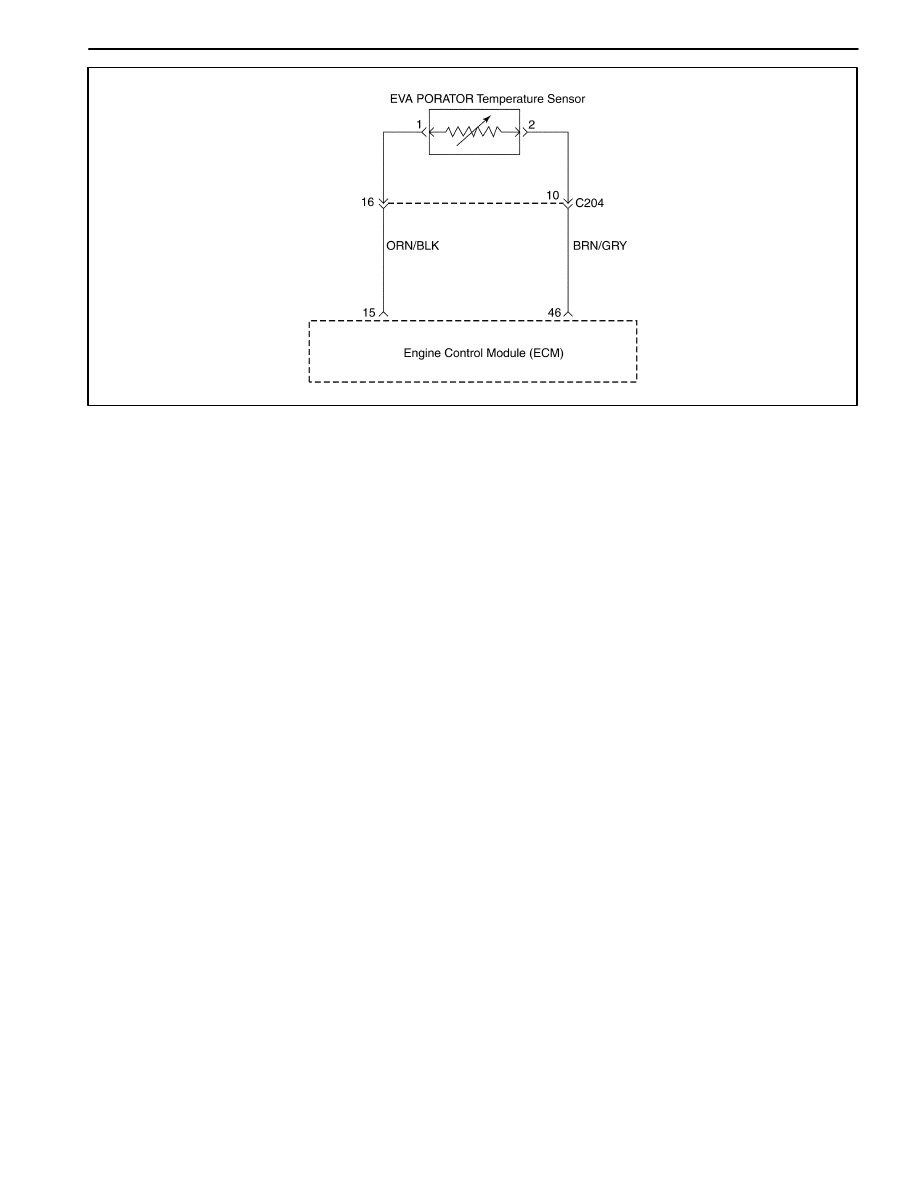
1F – 252 ENGINE CONTROLS
DAEWOO M-150 BL2
MAA1F300
DIAGNOSTIC TROUBLE CODE (DTC) – P1536 EVAPORATOR TEMPERATURE
SENSOR LOW VOLTAGE
Circuit Description
A semiconductor which resistance is noticeably
changed as the change of temperature. When the refrig-
erant temperature of the evaporator drops to 0
°
C (0
°
F)
and below, the evaporator cores get stuck with frost or
ice, reducing the airflow, lowering the cooling capacity.
The thermistor is a sensor which is used to prevent from
frosting or icing. The thermistor is installed on the evap-
orator.
Conditions for Setting the DTC
D
A short to battery voltage condition exists and is pres-
ent for more the 2 seconds.
Action Taken When the DTC Sets
D
The ECM will not illuminate the Malfunction Indicator
Lamp (MIL).
D
A history DTCs is stored.
D
The ECM will record operating conditions at the time
the diagnostic fails. This information will be stored
Failure Records buffers.
D
The A/C compressor operation will be disabled while
the low voltage indication exists.
D
Update the fail record each time the diagnostic test
fail.
Conditions for Clearing the MIL/DTC
D
A history DTC will clear after 40 consecutive warm-up
cycles without a fault.
D
Usisng the scan tool can clear DTC(s).
D
Disconnecting the ECM battery feed for 10 seconds.

ENGINE CONTROLS 1F – 253
DAEWOO M-150 BL2
DTC P1536 – Evaporator Temperature Sensor Low Voltage
Step
Action
Value(s)
Yes
No
1
Perform an On-Board Diagnostic (EOBD II) System
Check.
Is the system check complete?
–
Go to Step 2
Go to
“On-Board
Diagnostic
System Check”
2
2..Turn the ignition switch to LOCK.
2. Disconnect the evaporator temperature sensor.
3. Measure the resistance between evaporator
temperature sensor terminals 1 and 2.
Does the resistance within the specified value?
0
Ω
Go to Step 7
Go to Step 3
3
1. Turn the ignition switch to LOCK.
2. With the test light, connected to ground, probe
the ignition feed circuit, at terminal 2 in the sensor
harness connector.
Does the test light illuminate?
–
Go to Step 4
Go to Step 5
4
Repair a short to battery between the terminal 46 of
ECM and A/C compressor relay terminal 2.
Is the repair complete?
–
Go to Step 9
–
5
1. Turn the ignition switch to LOCK.
2. Disconnect the ECM.
3. With the test light, connected to ground, probe
the ignition feed circuit, at terminal 2 in the sensor
harness connector.
Does the test light illuminate?
–
Go to Step 6
Go to Step 8
6
Repair a short to battery between the ECM wiring
connector terminal 46 and evaporator temperature
sensor terminal 2.
Is the repair complete?
–
Go to Step 9
–
7
Replace the evaporator temperature sensor.
Is the replacement complete?
–
Go to Step 9
–
8
1. Turn the ignition switch to LOCK.
2. Replace the ECM.
Is the repair complete?
–
Go to Step 9
–
9
1. Using the scan tool, clear the Diagnostic Trouble
Codes(DTCs)
2. Start the engine and idle at normal operating
temperature.
3. Operate the vehicle within the conditions for
setting this DTC as specified in the supporting
text.
Does the scan tool indicate that this diagnostic has
run and passed?
–
Go to Step 10
Go to Step 2
10
Check if any additional DTCs are set.
Are any DTCs displayed that that have not been
diagnosed?
–
Go to
applicable DTC
table
System OK

1F – 254 ENGINE CONTROLS
DAEWOO M-150 BL2
MAA1F310
DIAGNOSTIC TROUBLE CODE (DTC) – P1537 A/C COMPRESSOR RELAY HIGH
VOLTAGE
Circuit Description
The A/C system uses an A/C refrigerant pressure sen-
sor mounted in the high pressure side of the A/C refrig-
erant system to monitor A/C refrigerant pressure. The
engine control module (ECM) uses this information to
turn ON the engine coolant fans when the A/C refriger-
ant pressure is high and to keep the compressor disen-
gaged when A/C refrigerant pressure is excessively high
or low.
Conditions for Setting the DTC
D
A/C compressor relay circuit short to battery.
Action Taken When the DTC Sets
D
The Malfunction Indicator Lamp (MIL) will not illumi-
nate.
D
The ECM will store conditions which were present
when the DTC was set as Failure Records data only.
D
This information will not be stored in the Freeze
Frame data.
Conditions for Clearing the MIL/DTC
D
A history DTC will clear after 40 consecutive warm-up
cycles without a fault.
D
DTC(s) can be cleared by using the scan tool.
Diagnostic Aids
Inspect harness connectors for backed-out terminals,
improper mating, broken locks, improperly formed or
damaged terminals, and poor terminal-to-wire connec-
tion at the ECM.
Inspect the wiring harness for damage. If the harness
appears to be OK, observe the A/C pressure display on
the scan tool while moving the connectors and wiring
harnesses related to the ACP sensor. A change in the
A/C pressure display will indicate the location of the
fault.
If DTC P1537 cannot be duplicated, reviewing the Fail
Records vehicle mileage since the diagnostic test last
failed may help determine how often the condition that
caused the DTC to set occurs. This may assist in diag-
nosing the condition.

ENGINE CONTROLS 1F – 255
DAEWOO M-150 BL2
DTC P1537 – A/C Compressor Relay High Voltage
Step
Action
Value(s)
Yes
No
1
Perform an On-Board Diagnostic (EOBD) System
Check.
Is the system check complete?
–
Go to Step 2
Go to
“On-Board
Diagnostic
System Check”
2
3..Turn the ignition switch to LOCK.
2. Disconnect the A/C compressor relay.
3. Measure the resistance between A/C compressor
relay terminals 85 and 86.
Does the resistance within the specified value?
0
Ω
Go to Step 3
Go to Step 7
3
1. Turn the ignition switch to LOCK.
2. With the test light, connected to ground, probe
the ignition feed circuit, at terminal 86 in the relay
harness connector.
Does the test light illuminate?
–
Go to Step 5
Go to Step 4
4
Repair a short to battery voltage between the
ignition switch terminal and A/C compressor relay
terminal 86.
Is the repair complete?
–
Go to Step 9
–
5
1. Turn the ignition switch to LOCK.
2. Disconnect the ECM.
3. With the test light, connected to ground, probe
the ignition feed circuit, at terminal 86 in the relay
harness connector.
Does the test light illuminate?
–
Go to Step 8
Go to Step 6
6
Repair a short to battery voltage between the ECM
wiring connector terminal 38 and A/C compressor
relay terminal 85.
Is the repair complete?
–
Go to Step 9
–
7
Replace the A/C compressor relay.
Is the replacement complete?
–
Go to Step 9
–
8
1. Turn the ignition switch to LOCK.
2. Replace the ECM.
Is the repair complete?
–
Go to Step 9
–
9
1. Using the scan tool, clear the Diagnostic Trouble
Codes(DTCs)
2. Start the engine and idle at normal operating
temperature.
3. Operate the vehicle within the conditions for
setting this DTC as specified in the supporting
text.
Does the scan tool indicate that this diagnostic has
run and passed?
–
Go to Step 10
Go to Step 2
10
Check if any additional DTCs are set.
Are any DTCs displayed that that have not been
diagnosed?
–
Go to
applicable DTC
table
System OK
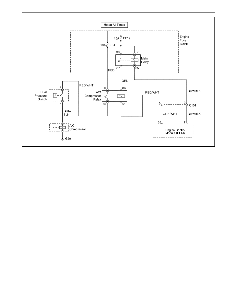
1F – 256 ENGINE CONTROLS
DAEWOO M-150 BL2
MAA1F310
DIAGNOSTIC TROUBLE CODE (DTC) – P1538 A/C COMPRESSOR RELAY LOW
VOLTAGE
Circuit Description
The A/C system uses an A/C refrigerant pressure sen-
sor mounted in the high pressure side of the A/C refrig-
erant system to monitor A/C refrigerant pressure. The
engine control module (ECM) uses this information to
turn ON the engine coolant fans when the A/C refriger-
ant pressure is high and to keep the compressor disen-
gaged when A/C refrigerant pressure is excessively high
or low.
Conditions for Setting the DTC
D
A/C compressor relay circuit short to ground or open.
Action Taken When the DTC Sets
D
The Malfunction Indicator Lamp (MIL) will not illumi-
nate.
D
The ECM will store conditions which were present
when the DTC was set as Failure Records data only.
D
This information will not be stored in the Freeze
Frame data.
Conditions for Clearing the MIL/DTC
D
A history DTC will clear after 40 consecutive warm-up
cycles without a fault.
D
DTC(s) can be cleared by using the scan tool.
Diagnostic Aids
Inspect harness connectors for backed-out terminals,
improper mating, broken locks, improperly formed or
damaged terminals, and poor terminal-to-wire connec-
tion at the ECM.
Inspect the wiring harness for damage. If the harness
appears to be OK, observe the A/C pressure display on
the scan tool while moving the connectors and wiring
harnesses related to the ACP sensor. A change in the
A/C pressure display will indicate the location of the
fault.
If DTC P1538 cannot be duplicated, reviewing the Fail
Records vehicle mileage since the diagnostic test last
failed may help determine how often the condition that
caused the DTC to set occurs. This may assist in diag-
nosing the condition.

ENGINE CONTROLS 1F – 257
DAEWOO M-150 BL2
DTC P1538 – A/C Compressor Relay Low Voltage
Step
Action
Value(s)
Yes
No
1
Perform an On-Board Diagnostic (EOBD) System
Check.
Is the system check complete?
–
Go to Step 2
Go to
“On-Board
Diagnostic
System Check”
2
1. Turn the ignition switch to LOCK.
2. Disconnect the A/C compressor relay.
3. Measure the resistance between A/C compressor
relay terminals 85 and 86.
Does the resistance within the specified value?
0
Ω
Go to Step 3
Go to Step 7
3
1. Turn the ignition switch to LOCK.
2. With the test light, connected to ground, probe
the ignition feed circuit, at terminal 86 in the relay
harness connector.
Does the test light illuminate?
–
Go to Step 5
Go to Step 4
4
Repair a short to ground between the ignition switch
terminal 4 and A/C compressor relay terminal 86.
Is the repair complete?
–
Go to Step 9
–
5
1. 1.
Turn the ignition switch to LOCK.
2. Disconnect the ECM.
3. With the test light, connected to ground, probe
the ignition feed circuit, at terminal 86 in the relay
harness connector.
Does the test light illuminate?
–
Go to Step 8
Go to Step 6
6
Repair a short to ground between the ECM wiring
connector terminal 38 and A/C compressor relay
terminal 85.
Is the repair complete?
–
Go to Step 9
–
7
Replace the A/C compressor relay.
Is the replacement complete?
–
Go to Step 9
–
8
1. Turn the ignition switch to LOCK.
2. Replace the ECM.
Is the repair complete?
–
Go to Step 9
–
9
1. Using the scan tool, clear the Diagnostic Trouble
Codes(DTCs)
2. Start the engine and idle at normal operating
temperature.
3. Operate the vehicle within the conditions for
setting this DTC as specified in the supporting
text.
Does the scan tool indicate that this diagnostic has
run and passed?
–
Go to Step 10
Go to Step 2
10
Check if any additional DTCs are set.
Are any DTCs displayed that that have not been
diagnosed?
–
Go to
applicable DTC
table
System OK
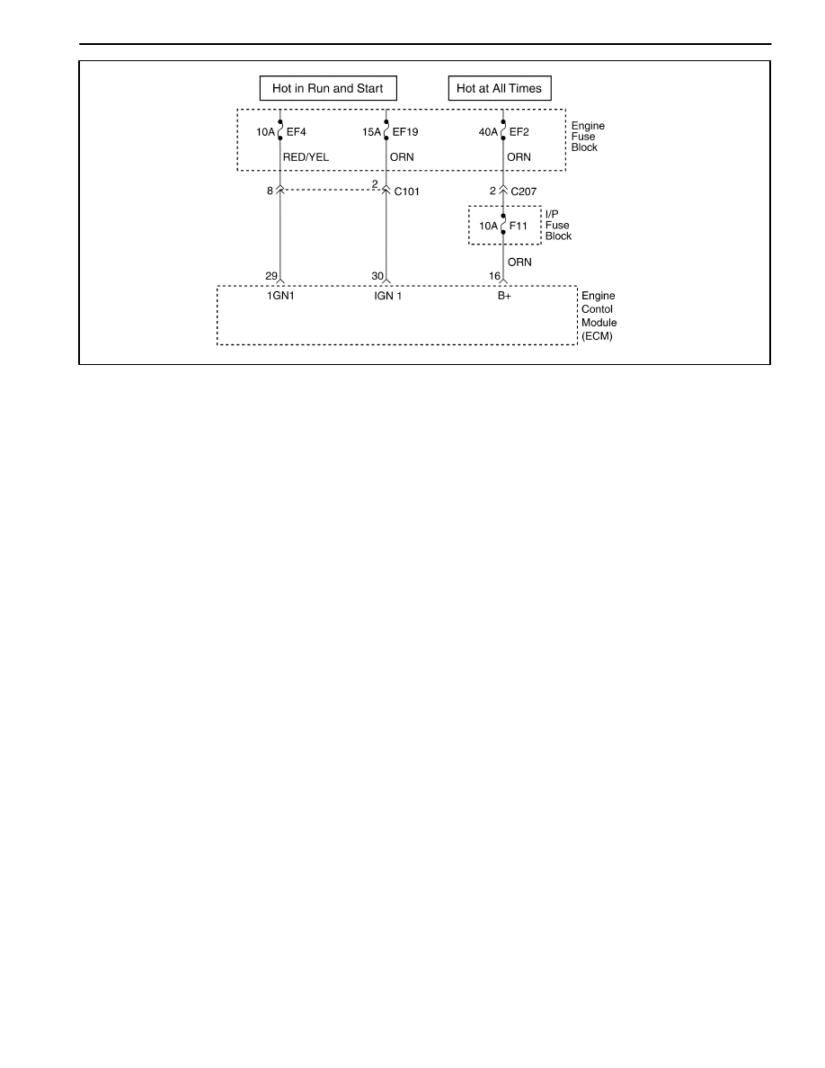
1F – 258 ENGINE CONTROLS
DAEWOO M-150 BL2
MAA1F320
DIAGNOSTIC TROUBLE CODE (DTC) – P0562 SYSTEM VOLTAGE(ENGINE
SIDE) TOO LOW
Circuit Description
The engine control module (ECM) monitors the ignition
voltage on the ignition feed circuit to terminal 7 at the
ECM. A system voltage Diagnostic Trouble Code (DTC)
sill set whenever the voltage is below a calibrated value.
Conditions for Setting the DTC
D
Ignition ON.
D
Main relay is ON.
D
The ignition voltage is less than 11.5 volt.
D
The main relay voltage is less than 5.0V or higher
than 26V during 7.6 seconds.
Action Taken When the DTC Sets
D
The Malfunction Indicator Lamp (MIL) will not illumi-
nate.
D
The ECM will store conditions which were present
when the DTC was set as Failure Records data only.
D
This information will not be stored in the Freeze
Frame data.
Conditions for Clearing the MIL/DTC
D
A history DTC will clear after 40 consecutive warm-up
cycles without a fault.
D
DTC(s) can be cleared by using the scan tool.
Diagnostic Aids
An Intermittent problem may be caused by a poor con-
nection, rubbed through wire insulation, or wire that is
broken inside the insulation.
Any circuitry, that is suspected as causing the com-
plaint, should be thoroughly checked for the following
conditions.
D
Backed-out terminals
D
Improper mating
D
Broken locks
D
Improperly formed
D
Damaged terminals
D
Poor terminals to wire connection
D
Physical damage to the wiring harness

ENGINE CONTROLS 1F – 259
DAEWOO M-150 BL2
DTC P0562 – System Voltage (Engine Side) Too Low
Step
Action
Value(s)
Yes
No
1
Perform an On-Board Diagnostic (EOBD) System
Check.
Is the system check complete?
–
Go to Step 2
Go to
“On-Board
Diagnostic
System Check”
2
1. Install a scan tool and clear the Diagnostic
Trouble Codes (DTCs).
2. Start the engine and raise the engine speed to
the specified value.
3. Load the electrical system by turning on the
headlights, high blower motor, etc.
Is the ignition voltage less than the specified value?
1,400rpm 10V
Go to Step 3
Go to Step 8
3
1. With the engine still running at the specified
value.
2. Using a digital voltmeter(DVM), measure the
battery voltage at the battery.
Is the battery voltage greater than the specified
value?
1,400rpm 12V
Go to Step 4
Go to
“Diagnostic
Aids”
4
1. Turn the ignition switch to LOCK.
2. Disconnect the engine control module(ECM)
connector at the ECM.
3. Turn the Turn the ignition switch to ON with the
engine OFF.
4 Using a DVM, measure the ignition voltage at the
ignition feed circuit, terminal 29.
Is the ignition voltage greater than the specified
value?
10V
Go to Step 5
Go to Step 6
5
Check for a malfunctioning connection at the ECM
harness terminals and repair as necessary.
Is a repair necessary?
–
Go to Step 8
Go to Step 7
6
Repair the poor connection (high resistance) in the
ignition feed circuit.
Is the repair complete?
–
Go to Step 8
–
7
Replace the ECM.
Is the replacement complete?
–
Go to Step 8
–
8
1 Using the scan tool, clear the DTCs.
2. Start the engine and idle at normal operating
temperature.
3. Operate the vehicle within the conditions for
setting this DTC ad specified in the supporting
text.
Does the scan tool indicate that this diagnostic has
run and passed?
–
Go to Step 9
Go to Step 2
9
Check if any additional DTCs are set.
Are any DTCs displayed that have not been
diagnosed?
–
Go to
applicable DTC
table
System OK

1F – 260 ENGINE CONTROLS
DAEWOO M-150 BL2
MAA1F320
DIAGNOSTIC TROUBLE CODE (DTC) – P0563 SYSTEM VOLTAGE (ENGINE
SIDE) TOO HIGH
Circuit Description
The engine control module (ECM) monitors the ignition
voltage on the ignition feed circuit to terminal 7 at the
ECM. A system voltage Diagnostic Trouble Code (DTC)
sill set whenever the voltage is below a calibrated value.
Conditions for Setting the DTC
D
Ignition ON.
D
The ignition voltage is greater than 16 volt.
Action Taken When the DTC Sets
D
The Malfunction Indicator Lamp (MIL) will not illumi-
nate.
D
The ECM will store conditions which were present
when the DTC was set as Failure Records data only.
D
This information will not be stored in the Freeze
Frame data.
Conditions for Clearing the MIL/DTC
D
A history DTC will clear after 40 consecutive warm-up
cycles without a fault.
D
DTC(s) can be cleared by using the scan tool.
D
Disconnecting the ECM battery feed for more than 10
seconds.
Diagnostic Aids
An Intermittent problem may be caused by a poor con-
nection, rubbed through wire insulation, or wire that is
broken inside the insulation.
Any circuitry, that is suspected as causing the com-
plaint, should be thoroughly checked for the following
conditions.
D
Backed-out terminals
D
Improper mating
D
Broken locks
D
Improperly formed
D
Damaged terminals
D
Poor terminals to wire connection
D
Physical damage to the wiring harness

ENGINE CONTROLS 1F – 261
DAEWOO M-150 BL2
DTC P0563 – System Voltage (Engine Side) Too High
Step
Action
Value(s)
Yes
No
1
Perform an On-Board Diagnostic (EOBD) System
Check.
Is the system check complete?
–
Go to Step 2
Go to
“On-Board
Diagnostic
System Check”
2
1. Install a scan tool and clear the Diagnostic
Trouble Codes (DTCs).
2. Start the engine and raise the engine speed to
the specified value.
3. Load the electrical system by turning on the
headlights, high blower motor, etc.
Is the ignition voltage less than the specified value?
1,400rpm 10V
Go to Step 3
Go to Step 8
3
1. With the engine still running at the specified
value.
2. Using a digital voltmeter(DVM), measure the
battery voltage at the battery.
Is the battery voltage greater than the specified
value?
1,400rpm 12V
Go to Step 4
Go to
“Diagnostic
Aids”
4
1. Turn the ignition switch to LOCK.
2. Disconnect the engine control module(ECM)
connector at the ECM.
3. Turn the Turn the ignition switch to ON with the
engine OFF.
4. Using a DVM, measure the ignition voltage at the
ignition feed circuit, terminal 29.
Is the ignition voltage greater than the specified
value?
10V
Go to Step 5
Go to Step 6
5
Check for a malfunctioning connection at the ECM
harness terminals and repair as necessary.
Is a repair necessary?
–
Go to Step 8
Go to Step 7
6
Repair the poor connection (high resistance) in the
ignition feed circuit.
Is the repair complete?
–
Go to Step 8
–
7
Replace the ECM.
Is the replacement complete?
–
Go to Step 8
–
8
1. Using the scan tool, clear the DTCs.
2. Start the engine and idle at normal operating
temperature.
3. Operate the vehicle within the conditions for
setting this DTC ad specified in the supporting
text.
Does the scan tool indicate that this diagnostic has
run and passed?
–
Go to Step 9
Go to Step 2
9
Check if any additional DTCs are set.
Are any DTCs displayed that have not been
diagnosed?
–
Go to
applicable DTC
table
System OK

1F – 262 ENGINE CONTROLS
DAEWOO M-150 BL2
DIAGNOSTIC TROUBLE CODE (DTC) – P0601 ENGINE CONTROL MODULE
CHECKSUM ERROR
Circuit Description
The engine control module (ECM) is the control center
of the fuel injection system. It constantly looks at the in-
formation from various sensors, and controls the sys-
tems that after vehicle performance. The ECM also
performs the diagnostic function of the system. It can
recognize operational problems, alert the driver through
the Malfunction Indicator Lamp (MIL), and store a Diag-
nostic Trouble Code (DTC) or DTCs which identify the
problem areas to aid the technician in making repairs.
An electrically erasable programmable read only
memory (EEPROM) is used to house the program infor-
mation and the calibrations required for engine, trans-
axle, transaxle diagnostics operation. The ECM uses a
value called a checksum for error detection of the soft-
ware. The checksum is a value that is equal to all the
numbers in the software added together. The ECM adds
all the values in the software and if that value does not
equal the checksum value, a checksum error is indi-
cated.
Conditions for Setting the DTC
D
The ECM detects more than 3 incorrect checksum.
Action Taken When the DTC Sets
D
The Malfunction Indicator Lamp (MIL) will not illumi-
nate.
D
The ECM will store conditions which were present
when the DTC was set as Failure Records data only.
D
This information will not be stored in the Freeze
Frame data.
Conditions for Clearing the MIL/DTC
D
A history DTC will clear after 40 consecutive warm-up
cycles without a fault.
D
DTC(s) can be cleared by using the scan tool.
DTC P0601– Engine Control Module Checksum Error
Step
Action
Value(s)
Yes
No
1
Perform an On-Board Diagnostic (EOBD) System
Check.
Is the system check complete?
–
Go to Step 2
Go to
“On-Board
Diagnostic
System Check”
2
Replace the engine control module(ECM).
Is the replacement complete?
–
Go to Step 3
–
3
1. Using the scan tool, clear the DTCs.
2. Start the engine and idle at normal operating
temperature.
3. Operate the vehicle within the conditions for
setting this DTC ad specified in the supporting
text.
Does the scan tool indicate that this diagnostic has
run and passed?
–
Go to Step 4
Go to Step 2
4
Check if any additional DTCs are set.
Are any DTCs displayed that have not been
diagnosed?
–
Go to
applicable DTC
table
System OK

ENGINE CONTROLS 1F – 263
DAEWOO M-150 BL2
DIAGNOSTIC TROUBLE CODE (DTC) – P0604 ENGINE CONTROL MODULE
INTERNAL/EXTERNAL RAM ERROR
Circuit Description
The engine control module (ECM) is the control center
of the fuel injection system. It constantly looks at the in-
formation from various sensors, and controls the sys-
tems that after vehicle performance. The ECM also
performs the diagnostic function of the system. It can
recognize operational problems, alert the driver through
the Malfunction Indicator Lamp (MIL), and store a Diag-
nostic Trouble Code (DTC) or DTCs which identify the
problem areas to aid the technician in making repairs.
An electrically erasable programmable read only
memory (EEPROM) is used to house the program infor-
mation and the calibrations required for engine, trans-
axle, transaxle diagnostics operation. The ECM uses a
value called a checksum for error detection of the soft-
ware. The checksum is a value that is equal to all the
numbers in the software added together. The ECM adds
all the values in the software and if that value does not
equal the checksum value, a checksum error is indi-
cated.
Conditions for Setting the DTC
D
The ECM detects more than 3 incorrect checksum.
Action taken when The DTCs Sets
D
The Malfunction Indicator Lamp (MIL) will illuminate.
D
The ECM will record operating conditions at the time
the diagnostic fails. This information will be stored in
the Freeze Frame and Failure Records buffers.
D
A history DTC is stored.
D
Coolant fan turns on.
Conditions for Clearing the MIL/DTC
D
The MIL will turn off after four consecutive ignition
cycles in which the diagnostic runs without a fault.
D
A history DTC will clear after 40 consecutive warm-up
cycles without a fault.
D
DTC(s) can be cleared by using the scan tool.
DTC P0604 – Engine Control Module RAM Error
Step
Action
Value(s)
Yes
No
1
Perform an On-Board Diagnostic (EOBD) System
Check.
Is the system check complete?
–
Go to Step 2
Go to
“On-Board
Diagnostic
System Check”
2
Replace the engine control module(ECM).
Is the replacement complete?
–
Go to Step 3
–
3
1. Using the scan tool, clear the DTCs.
2. Start the engine and idle at normal operating
temperature.
3. Operate the vehicle within the conditions for
setting this DTC ad specified in the supporting
text.
Does the scan tool indicate that this diagnostic has
run and passed?
–
Go to Step 4
Go to Step 2
4
Check if any additional DTCs are set.
Are any DTCs displayed that have not been
diagnosed?
–
Go to
applicable DTC
table
System OK

1F – 264 ENGINE CONTROLS
DAEWOO M-150 BL2
DIAGNOSTIC TROUBLE CODE (DTC) – P0605 ENGINE CONTROL MODULE
NMVY WRITE ERROR
Circuit Description
The engine control module (ECM) is the control center of
the fuel injection system. It constantly looks at the infor-
mation from various sensors, and controls the systems
that after vehicle performance. The ECM also performs
the diagnostic function of the system. It can recognize op-
erational problems, alert the driver through the Malfunc-
tion Indicator Lamp (MIL), and store a Diagnostic Trouble
Code (DTC) or DTCs which identify the problem areas to
aid the technician in making repairs. An electrically eras-
able programmable read only memory (EEPROM) is
used to house the program information and the calibra-
tions required for engine, transaxle, transaxle diagnos-
tics operation. The ECM uses a value called a checksum
for error detection of the software. The checksum is a val-
ue that is equal to all the numbers in the software added
together. The ECM adds all the values in the software
and if that value does not equal the checksum value, a
checksum error is indicated.
Conditions for Setting the DTC
D
The ECM detects more than 3 incorrect checksum.
Action taken when The DTCs Sets
D
The Malfunction Indicator Lamp (MIL) will illuminate.
D
The ECM will record operating conditions at the time
the diagnostic fails. This information will be stored in
the Freeze Frame and Failure Records buffers.
D
A history DTC is stored.
D
Coolant fan turns on.
Conditions for Clearing the MIL/DTC
D
The MIL will turn off after four consecutive ignition
cycles in which the diagnostic runs without a fault.
D
A history DTC will clear after 40 consecutive warm-up
cycles without a fault.
D
DTC(s) can be cleared by using the scan tool.
DTC P0605 Engine Control Module NMVY Write Error
Step
Action
Value(s)
Yes
No
1
Perform an On-Board Diagnostic (EOBD) System
Check.
Is the system check complete?
–
Go to Step 2
Go to
“On-Board
Diagnostic
System Check”
2
Replace the engine control module(ECM).
Is the replacement complete?
–
Go to Step 3
–
3
1. Using the scan tool, clear the DTCs.
2. Start the engine and idle at normal operating
temperature.
3. Operate the vehicle within the conditions for
setting this DTC ad specified in the supporting
text.
Does the scan tool indicate that this diagnostic has
run and passed?
–
Go to Step 4
Go to Step 2
4
Check if any additional DTCs are set.
Are any DTCs displayed that have not been
diagnosed?
–
Go to
applicable DTC
table
System OK

ENGINE CONTROLS 1F – 265
DAEWOO M-150 BL2
BLANK
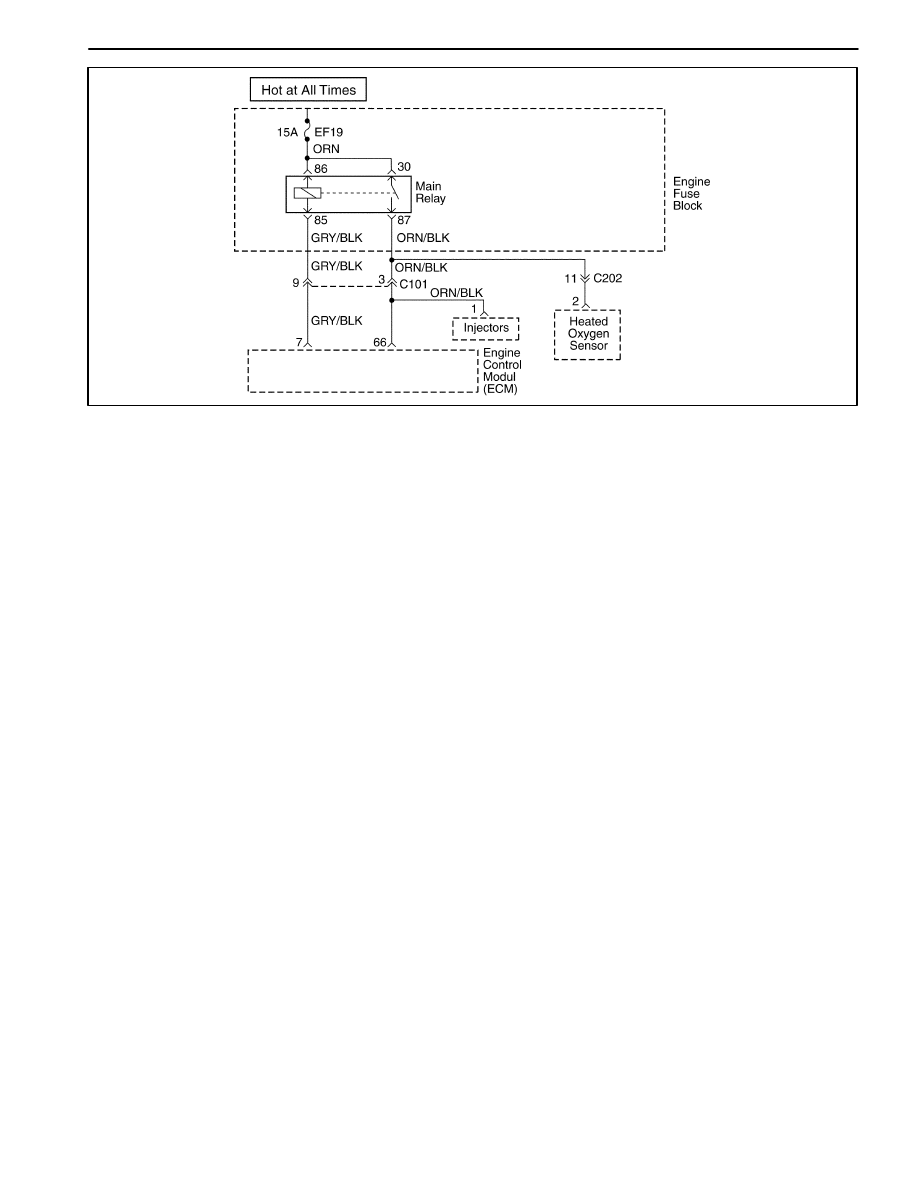
1F – 266 ENGINE CONTROLS
DAEWOO M-150 BL2
MAA1F050
DIAGNOSTIC TROUBLE CODE (DTC) – P1610 MAIN RELAY HIGH VOLTAGE
Circuit Description
When the ignition switch to ON, main relay will grounded
to ECM internal ground by ECM controlling.
A system voltage Diagnostic Trouble Code (DTC) will
set whenever the voltage is below a calibrated value.
Conditions for Setting the DTC
D
This DTC can be stored in “key-on” status.
D
Main relay wiring harness high voltage.
Action Taken When The DTCs Sets
D
The Malfunction Indicator Lamp (MIL) will illuminate.
D
The ECM will record operating conditions at the time
the diagnostic fails. This information will be stored in
the Freeze Frame and failure records buffers.
D
A history DTC is stored.
Conditions for Clearing the MIL/DTC
D
The MIL will turn off after four consecutive ignition
cycles in which the diagnostic runs without a fault.
D
A history DTC will clear after 40 consecutive warm up
cycles without a fault.
D
Using the scan tool can clear DTC(s).
Diagnostic Aids
Inspect harness connectors for backed-out terminals,
improper mating, broken locks, improperly formed or
damaged terminals, and poor terminal-to-wire connec-
tion at the ECM.
Inspect the wiring harness for damage. If the harness
appears to be OK, observe the A/C pressure display on
the scan tool while moving the connectors and wiring
harnesses related to the ACP sensor. A change in the
A/C pressure display will indicate the location of the
fault.
If DTC P1610 cannot be duplicated, reviewing the Fail
Records vehicle mileage since the diagnostic test last
failed may help determine how often the condition that
caused the DTC to set occurs. This may assist in diag-
nosing the condition.

ENGINE CONTROLS 1F – 267
DAEWOO M-150 BL2
DTC P1610 – Main Relay High Voltage
Step
Action
Value(s)
Yes
No
1
Perform an On-Board Diagnostic (EOBD) System
Check.
Is the system check complete?
–
Go to Step 2
Go to
“On-Board
Diagnostic
System Check”
2
1. Disconnect the main relay.
2. Measure the resistance between main relay
terminals 85 and 86.
Does the resistance within the specified value?
75~85
Ω
Go to Step 3
Go to Step 6
3
1. Turn the ignition switch to LOCK.
2. With the test light, connected to ground, probe
the ignition feed circuit, at terminal 85 in the relay
harness connector.
Does the test light illuminate?
–
Go to Step 4
Go to
“Diagnostic
Aids”
4
1. Turn the ignition switch to LOCK.
2. Disconnect the ECM wiring harness connector.
3. With the test light, connected to ground, probe
the ignition feed circuit, at terminal 85 in the relay
harness connector.
Does the test light illuminate?
–
Go to Step 5
Go to Step 7
5
Repair a high voltage between the ECM wiring
connector terminal 7 and main relay terminal 85.
Is the repair complete?
–
Go to Step 7
–
6
Replace the main relay.
Is the replacement complete?
–
Go to Step 7
–
7
1. Using the scan tool, clear the Diagnostic Trouble
Codes(DTCs)
2. Start the engine and idle at normal operating
temperature.
3. Operate the vehicle within the conditions for
setting this DTC as specified in the supporting
text.
Does the scan tool indicate that this diagnostic has
run and passed?
–
Go to Step 8
Go to Step 2
8
Check if any additional DTCs are set.
Are any DTCs displayed that that have not been
diagnosed?
–
Go to
applicable DTC
table
System OK

1F – 268 ENGINE CONTROLS
DAEWOO M-150 BL2
MAA1F050
DIAGNOSTIC TROUBLE CODE (DTC) – P1611 MAIN RELAY LOW VOLTAGE
Circuit Description
When the ignition switch to ON, main relay will grounded
to ECM internal ground by ECM controlling.
A system voltage Diagnostic Trouble Code (DTC) will
set whenever the voltage is below a calibrated value.
Conditions for Setting the DTC
D
This DTC can be stored in “key-on” status.
D
Main relay wiring harness high voltage.
Action Taken When The DTCs Sets
D
The ECM will illuminate the Malfunction Indicator
Lamp (MIL).
D
A history DTC is stored.
D
The ECM will record operating conditions at the time
the diagnostic fails. This information will be stored
Failure Records buffers.
Conditions for Clearing the MIL/DTC
D
The MIL will turn off after four consecutive ignition
cycles in which the diagnostic runs without a fault.
D
A history DTC will clear after 40 consecutive warm up
cycles without a fault.
D
Using the scan tool can clear DTC(s).
Diagnostic Aids
Inspect harness connectors for backed-out terminals,
improper mating, broken locks, improperly formed or
damaged terminals, and poor terminal-to-wire connec-
tion at the ECM.
Inspect the wiring harness for damage. If the harness
appears to be OK, observe the A/C pressure display on
the scan tool while moving the connectors and wiring
harnesses related to the ACP sensor. A change in the
A/C pressure display will indicate the location of the
fault.
If DTC P1611 cannot be duplicated, reviewing the Fail
Records vehicle mileage since the diagnostic test last
failed may help determine how often the condition that
caused the DTC to set occurs. This may assist in diag-
nosing the condition.

ENGINE CONTROLS 1F – 269
DAEWOO M-150 BL2
DTC P1611 – Main Relay Low Voltage
Step
Action
Value(s)
Yes
No
1
Perform an On-Board Diagnostic (EOBD) System
Check.
Is the system check complete?
–
Go to Step 2
Go to
“On-Board
Diagnostic
System Check”
2
1. Disconnect the main relay.
2. Measure the resistance between main relay
terminals 85 and 86.
Does the resistance within the specified value?
75~85
Ω
Go to Step 3
Go to Step 6
3
1. Turn the ignition switch to LOCK.
2. With the test light, connected to ground, probe
the ignition feed circuit, at terminal 85 in the relay
harness connector.
Does the test light illuminate?
–
Go to Step 4
Go to
“Diagnostic
Aids”
4
1. Turn the ignition switch to LOCK.
2. Disconnect the ECM wiring harness connector.
3. With the test light, connected to ground, probe
the ignition feed circuit, at terminal 85 in the relay
harness connector.
Does the test light illuminate?
–
Go to Step 5
Go to Step 7
5
Repair a high voltage between the ECM wiring
connector terminal 7 and main relay terminal 85.
Is the repair complete?
–
Go to Step 7
–
6
Replace the main relay.
Is the replacement complete?
–
Go to Step 7
–
7
1. Using the scan tool, clear the Diagnostic Trouble
Codes(DTCs)
2. Start the engine and idle at normal operating
temperature.
3. Operate the vehicle within the conditions for
setting this DTC as specified in the supporting
text.
Does the scan tool indicate that this diagnostic has
run and passed?
–
Go to Step 8
Go to Step 2
8
Check if any additional DTCs are set.
Are any DTCs displayed that that have not been
diagnosed?
–
Go to
applicable DTC
table
System OK
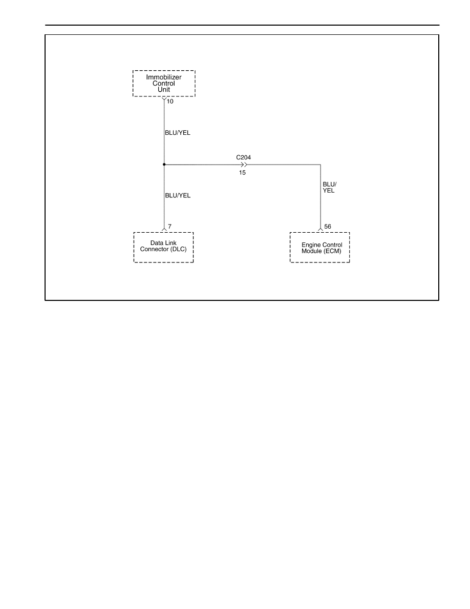
1F – 270 ENGINE CONTROLS
DAEWOO M-150 BL2
MAA1F330
DIAGNOSTIC TROUBLE CODE (DTC) – P1628 IMMOBILIZER NO SUCCESSFUL
COMMUNICATION
Circuit Description
When the ignition switch is turned to ON, the key tested
by immobilizer anti-theft system. While the key code is
being read by immobilizer control unit or integrated anti-
theft control unit, the engine can start run with any key
that will turn the lock cylinder. the key code is read and
compared with key codes that have been stored in the
memory of the immobilizer control unit. If a valid key is
detected, the immobilizer control unit sends a serial data
release message to the Engine Control Module (ECM).
Included in the release message is an identification (ID)
code which assures that neither the immobilizer control
unit nor the ECM have been substituted to defeat the
system. If the ECM receives an invalid release mes-
sage, the ECM performs the following action:
D
Disable the fuel injector circuit.
D
Disable the fuel pump circuit.
D
Disable the ignition coil.
D
A Diagnostic Trouble Code (DTC) will stored if detect
communication link failure between the ECM and im-
mobilizer control unit.
Conditions for Setting the DTC
D
Ignition switch is turned to ON.
D
Immobilizer option auto detected.
D
ECM release time window(1.5 or 2 seconds) expired.
D
Vehicle Speed Sensor (VSS) signal is less than 512
km/h.
Action Taken When the DTC Sets
D
The Malfunction Indicator Lamp (MIL) will not illumi-
nate.
D
The ECM will store conditions which were present
when the DTC was set as Failure Records data only.
D
This information will not be stored in the Freeze
Frame data.
Conditions for Clearing the MIL/DTC
D
A history DTC will clear after 40 consecutive warm-up
cycles without a fault.
D
DTC(s) can be cleared by using the scan tool.

ENGINE CONTROLS 1F – 271
DAEWOO M-150 BL2
DTC P1628 – Immobilizer No Successful Communication
Step
Action
Value(s)
Yes
No
1
Perform an On-Board Diagnostic (EOBD) System
Check.
Is the system check complete?
–
Go to Step 2
Go to
“On-Board
Diagnostic
System Check”
2
1. Turn the ignition OFF.
2. Install a scan too to the Data Link Connector
(DLC).
3. Turn the ignition ON.
4. Select IMMOBILIZER DIAGNOSIS STATUS from
the scan tool menu.
Is the communication established between the scan
tool and the immobilizer control unit?
–
Go to Step 3
Go to Section
9T, Immobilizer
Anti-Theft
System
3
1. Turn the ignition OFF.
2. Disconnect the Immobilizer Control Unit and
Engine Control Module (ECM) connectors.
3. Measure the resistance between terminal 7 of
immoblizer control unit and terminal 56 of the
ECM.
Is the resistance within the specified value?
0
Ω
Go to Step 5
Go to Step 4
4
Repair an open circuit between terminal 7 of
immobilizer control unit and terminal 56 of the ECM.
Is the repair complete?
–
Go to Step 8
–
5
Check the terminals in immobilizer control unit and
the ECM for damages and repair as needed.
Is the repair complete?
–
Go to Step 8
Go to Step 6
6
Replace the immobilizer control unit.
Is the repair complete?
–
Go to Step 8
Go to Step 7
7
1. Turn the ignition OFF.
2. Replace the ECM.
Is the repair complete?
–
Go to Step 8
–
8
1. Using the scan tool, clear the Diagnostic Trouble
Codes (DTCs).
2. Start the engine and idle at normal operating
temperature.
3. Operate the vehicle within the Conditions for
setting this DTC as specified in the supporting
text.
Does the scan tool indicate that this diagnostic has
run and passed?
–
Go to Step 9
Go to Step 2
9
Check if any additional DTCs are set.
Are any DTCs displayed that have not been
diagnosed?
–
Go to
Applicable DTC
Table
System OK

1F – 272 ENGINE CONTROLS
DAEWOO M-150 BL2
MAA1F330
DIAGNOSTIC TROUBLE CODE (DTC) – P1629 IMMOBILIZER WRONG
COMPUTATION
Circuit Description
When the ignition switch is turned to ON, the key tested
by immobilizer anti-theft system. While the key code is
being read by immobilizer control unit or integrated anti-
theft control unit, the engine can start run with any key
that will turn the lock cylinder. the key code is read and
compared with key codes that have been stored in the
memory of the immobilizer control unit. If a valid key is
detected, the immobilizer control unit sends a serial data
release message to the Engine Control Module (ECM).
Included in the release message is an identification (ID)
code which assures that neither the immobilizer control
unit nor the ECM have been substituted to defeat the
system. If the ECM receives an invalid release mes-
sage, the ECM performs the following action:
D
Disable the fuel injector circuit.
D
Disable the fuel pump circuit.
D
Disable the ignition coil.
A Diagnostic Trouble Code (DTC) will stored if detect
communication link failure between the ECM and immo-
bilizer control unit.
Conditions for Setting the DTC
D
Ignition switch is turned to ON.
D
Immobilizer option auto detected.
D
ECM release time window(1.5 or 2 seconds) expired.
D
Vehicle Speed Sensor (VSS) signal is less than 512
km/h.
Action Taken When the DTC Sets
D
The Malfunction Indicator Lamp (MIL) will not illumi-
nate.
D
The ECM will store conditions which were present
when the DTC was set as Failure Records data only.
D
This information will not be stored in the Freeze
Frame data.
Conditions for Clearing the MIL/DTC
D
A history DTC will clear after 40 consecutive warm-up
cycles without a fault.
D
DTC(s) can be cleared by using the scan tool.

ENGINE CONTROLS 1F – 273
DAEWOO M-150 BL2
DTC P1629 – Immobilizer Wrong Computation
Step
Action
Value(s)
Yes
No
1
Perform an On-Board Diagnostic (EOBD) System
Check.
Is the system check complete?
–
Go to Step 2
Go to
“On-Board
Diagnostic
System Check”
2
1. Turn the ignition OFF.
2. Install a scan too to the Data Link Connector
(DLC).
3. Turn the ignition ON.
4. Select IMMOBILIZER DIAGNOSIS STATUS from
the scan tool menu.
Is the communication established between the scan
tool and the immobilizer control unit?
–
Go to Step 3
Go to Section
9T, Immobilizer
Anti-Theft
System
3
1. Turn the ignition OFF.
2. Disconnect the Immobilizer Control Unit and
Engine Control Module (ECM) connectors.
3. Measure the resistance between terminal 7 of
immoblizer control unit and terminal 56 of the
ECM.
Is the resistance within the specified value?
0
Ω
Go to Step 5
Go to Step 4
4
Repair an open circuit between terminal 7 of
immobilizer control unit and terminal 56 of the ECM.
Is the repair complete?
–
Go to Step 8
–
5
Check the terminals in immobilizer control unit and
the ECM for damages and repair as needed.
Is the repair complete?
–
Go to Step 8
Go to Step 6
6
Replace the immobilizer control unit.
Is the repair complete?
–
Go to Step 8
Go to Step 7
7
1. Turn the ignition OFF.
2. Replace the ECM.
Is the repair complete?
–
Go to Step 8
–
8
1. Using the scan tool, clear the Diagnostic Trouble
Codes (DTCs).
2. Start the engine and idle at normal operating
temperature.
3. Operate the vehicle within the Conditions for
setting this DTC as specified in the supporting
text.
Does the scan tool indicate that this diagnostic has
run and passed?
–
Go to Step 9
Go to Step 2
9
Check if any additional DTCs are set.
Are any DTCs displayed that have not been
diagnosed?
–
Go to
Applicable DTC
Table
System OK
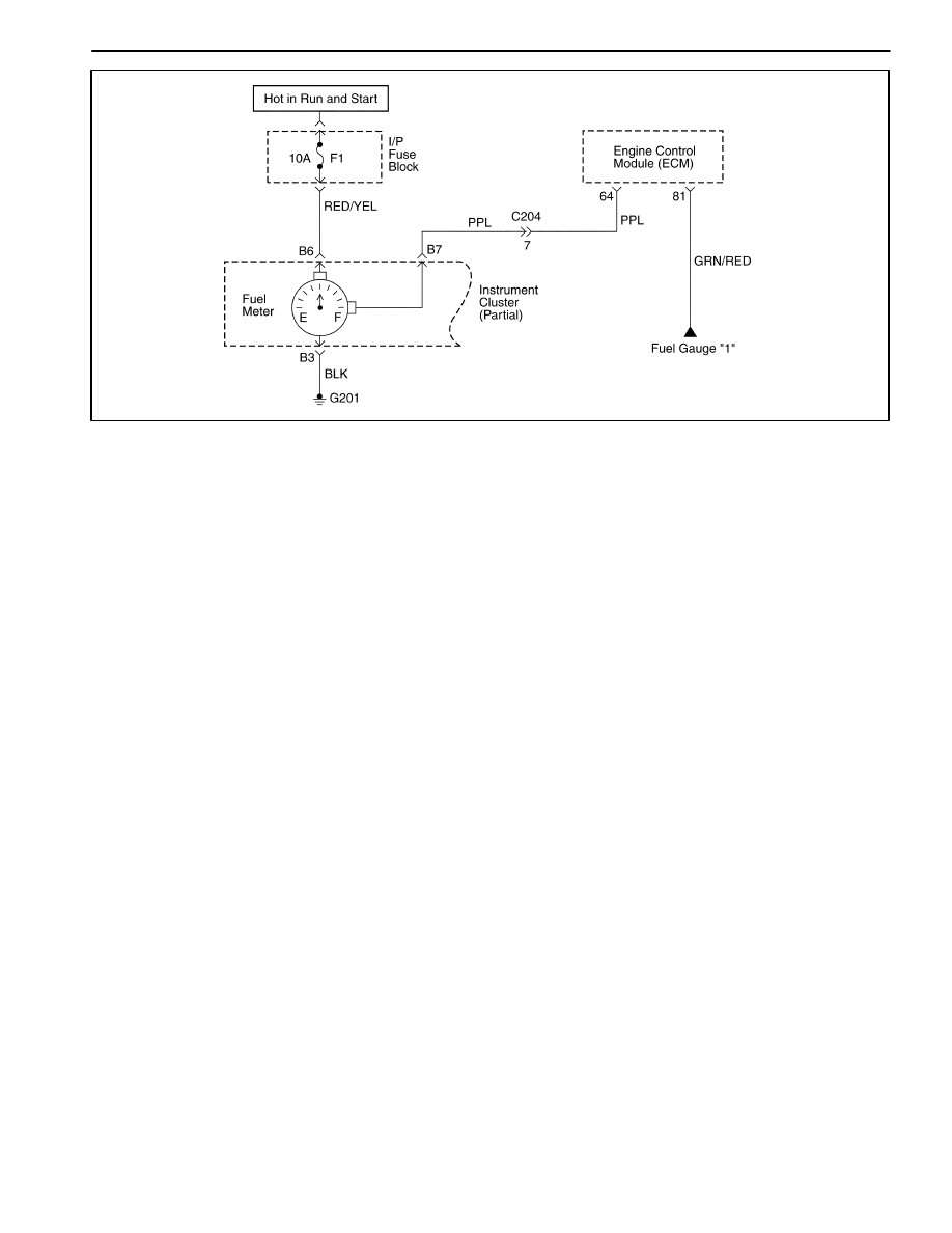
1F – 274 ENGINE CONTROLS
DAEWOO M-150 BL2
MAA1F340
DIAGNOSTIC TROUBLE CODE (DTC) – P0656 FUEL LEVEL GAUGE CIRCUIT
FAULT
Circuit Description
The engine control module(ECM) uses the fuel level in-
put from the Fuel Level Sensor to calculate expected va-
por pressures within the fuel system. Vapor pressure
vary as the fuel level changes. Vapor pressure is critical
in determining if the evaporative emission (EVAP) sys-
tem is operating properly. Fuel Level is also used to de-
termine if the Fuel level is too high or too low to be able
to accurately detect EVAP system faults. This Diagnos-
tic Trouble Code(DTC) detects a stuck fuel level sender.
Conditions for Setting the DTC
D
Fuel Level Sensor voltage is higher than 4.8V.
D
Fuel Level Sensor circuit high voltage.
Action Taken When the DTC Sets
D
The Malfunction Indicator Lamp (MIL) will not illumi-
nate.
D
The ECM will store conditions which were present
when the DTC was set as Failure Records data only.
D
This information will not be stored in the Freeze
Frame data.
Conditions for Clearing the MIL/DTC
D
A history DTC will clear after 40 consecutive warm-up
cycles without a fault.
D
DTC(s) can be cleared by using the scan tool.
Diagnostic Aids
Inspect harness connectors for backed-out terminal, im-
proper mating, broken locks, improperly formed or dam-
aged terminals, and poor terminal-to-wire connection.
Inspect the wiring harness for damage.
A stuck Fuel Level Sensor may cause the DTC to set. If
DTC P0656 cannot be duplicated, the information in-
cluded in the Freeze Frame data can be useful in deter-
mining vehicle operating conditions when the DTC was
first set.
Resistance check for the Fuel Level Sensor.
D
Empty = 100 ohms or over.
D
Half full = about 32.5 ohms.
D
Full = 10 ohms or less.

ENGINE CONTROLS 1F – 275
DAEWOO M-150 BL2
DTC P0656 – Fuel Level Gauge Circuit Fault
Step
Action
Value(s)
Yes
No
1
Perform an On-Board Diagnostic (EOBD) System
Check.
Is the system check complete?
–
Go to Step 2
Go to
“On-Board
Diagnostic
System Check”
2
1. Turn the ignition switch to LOCK.
2. connect the scan tool to the DLC.
3. Turn the Turn the ignition switch to ON.
Are any Diagnostic Trouble Codes (DTCs)
displayed?
–
Go to Step 3
Try with
another scan
tool
3
Refer to the applicable DTC table. Start with the
DTC with the lowest numerical value and move up.
Is the DTC identified as valid trouble code P0656?
–
Go to Step 4
Go to
applicable DTC
table
4
1. Disconnect the cluster connector
2. Turn the ignition switch to LOCK.
3. Check for an open or short to ground in the wire
between the cluster connector terminal C14 and
ground.
Is the problem found?
–
Go to Step 6
Go to Step 5
5
1. Turn the ignition switch to LOCK.
2. Check for short to battery in the wire between the
the cluster connector terminal C14 and ground.
Is the problem found?
–
Go to Step 6
Go to Step 7
6
1. Change the between cluster and ECM or repair
the connector terminal as needed.
2. Clear any DTCs from ECM.
3. Perform the diagnostic system check.
Is the repair complete?
–
System OK
–
7
1. Replace the cluster.
2. Clear any DTCs from ECM.
3. Perform the diagnostic system check.
Are any Diagnostic Trouble Codes (DTCs)
displayed?
–
Go to Step 8
System OK
8
Replace the ECM.
Is the replcement complete?
–
Go to Step 9
–
9
1. Using the scan tool, clear the Diagnostic Trouble
Codes(DTCs)
2. Start the engine and idle at normal operating
temperature.
3. Operate the vehicle within the conditions for
setting this DTC as specified in the supporting
text.
Does the scan tool indicate that this diagnostic has
run and passed?
–
Go to Step 10
Go to Step 2
10
Check if any additional DTCs are set.
Are any DTCs displayed that that have not been
diagnosed?
–
Go to
applicable DTC
table
System OK
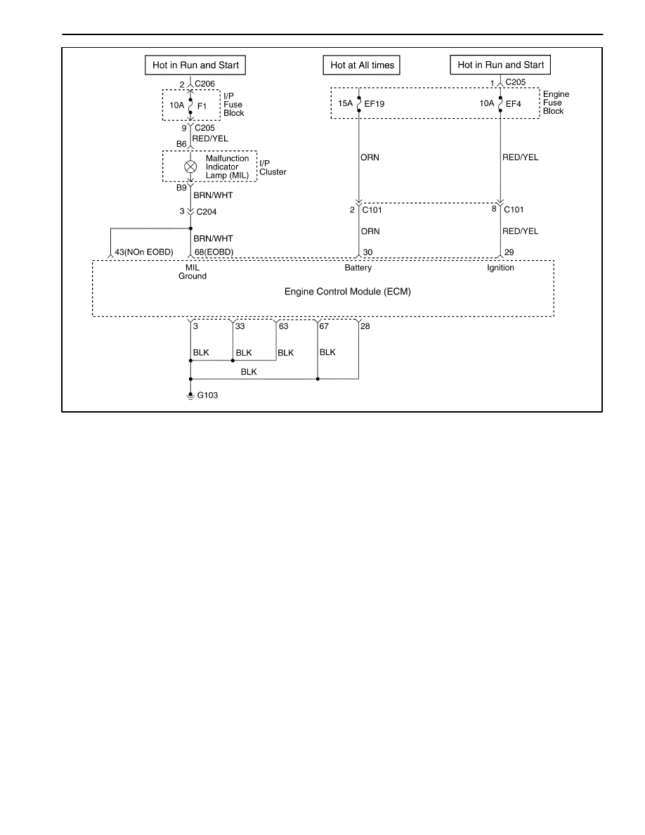
1F – 276 ENGINE CONTROLS
DAEWOO M-150 BL2
MAA1F030
DIAGNOSTIC TROUBLE CODE (DTC) – P1660 MALFUNCTION INDICATOR
LAMP (MIL) HIGH VOLTAGE
Circuit Description
When the ignition switch to ON, the Malfunction Indica-
tor Lamp (MIL) is ON steady.
When the engine cranking, the Malfunction Indicator
Lamp (MIL) is OFF after one flashing time.
If a system have some difficulties, the Malfunction Indi-
cator Lamp (MIL) is ON.
Conditions for Setting the DTC
D
The Malfunction Indicator Lamp (MIL) wiring harness
high voltage.
Action Taken When The DTCs Sets
D
The Malfunction Indicator Lamp (MIL) will illuminate.
D
The ECM will record operating conditions at the time
the diagnostic fails. This information will be stored in
the Freeze Frame and Failure Records buffers.
D
A history DTC is stored.
Conditions for Clearing the MIL/DTC
D
The MIL will turn off after four consecutive ignition
cycles in which the diagnostic runs without a fault.
D
A history DTC will clear after 40 consecutive warm-up
cycles without a fault.
D
DTC(s) can be cleared by using the scan tool.
Diagnostic Aids
An Intermittent problem may be caused by a poor con-
nection, rubbed through wire insulation, or wire that is
broken inside the insulation.
Any circuitry, that is suspected as causing the com-
plaint, should be thoroughly checked for the following
conditions.
D
Backed-out terminals
D
Improper mating
D
Broken locks
D
Improperly formed
D
Damaged terminals
D
Poor terminals to wire connection
D
Physical damage to the wiring harness

ENGINE CONTROLS 1F – 277
DAEWOO M-150 BL2
DTC P1660 – Malfunction Indicator Lamp (MIL) High Voltage
Step
Action
Value(s)
Yes
No
1
Perform an On-Board Diagnostic (EOBD) System
Check.
Is the system check complete?
–
Go to Step 2
Go to
“On-Board
Diagnostic
System Check”
2
1. Turn the ignition switch to LOCK.
2. Disconnect the cluster wiring connector.
3. With the test light, connected to ground, probe
the ignition feed circuit, at terminal A7 in the
harness connector.
Does the resistance within the specified value?
0
Ω
Go to Step 3
Go to Step 6
3
1. Turn the ignition switch to LOCK.
2. With the test light, connected to ground, probe
the ignition feed circuit, at ECM wiring connector
terminal 68.
Does the test light illuminate?
–
Go to Step 4
Go to Step 5
4
1. Turn the ignition switch to LOCK.
2. Replace the cluster.
Is the replacement complete?
–
Go to Step 6
–
5
Repair a short to battery between the ECM wiring
connector terminal 68 and cluster wiring connector
terminal B9.
Is the repair complete?
–
Go to Step 6
–
6
1. Using the scan tool, clear the Diagnostic Trouble
Codes(DTCs)
2. Start the engine and idle at normal operating
temperature.
3. Operate the vehicle within the conditions for
setting this DTC as specified in the supporting
text.
Does the scan tool indicate that this diagnostic has
run and passed?
–
Go to Step 7
Go to Step 2
7
Check if any additional DTCs are set.
Are any DTCs displayed that that have not been
diagnosed?
–
Go to
applicable DTC
table
System OK

1F – 278 ENGINE CONTROLS
DAEWOO M-150 BL2
MAA1F030
DIAGNOSTIC TROUBLE CODE (DTC) – P1661 MALFUNCTION INDICATOR
LAMP (MIL) LOW VOLTAGE
Circuit Description
When the ignition switch to ON, the Malfunction Indica-
tor Lamp (MIL) is ON steady.
When the engine cranking, the Malfunction Indicator
Lamp (MIL) is OFF after one flashing time.
If a system have some difficulties, the Malfunction Indi-
cator Lamp (MIL) is ON.
Conditions for Setting the DTC
D
The Malfunction Indicator Lamp (MIL) wiring harness
low voltage.
Action Taken When the DTC Sets
D
The Malfunction Indicator Lamp (MIL) will illuminate.
D
The ECM will record operating conditions at the time
the diagnostic fails. This information will be stored in
the Freeze Frame and Failure Records buffers.
D
A history DTC is stored.
Conditions for Clearing the MIL/DTC
D
The MIL will turn off after four consecutive ignition
cycles in which the diagnostic runs without a fault.
D
A history DTC will clear after 40 consecutive warm-up
cycles without a fault.
D
DTC(s) can be cleared by using the scan tool.
Diagnostic Aids
An Intermittent problem may be caused by a poor con-
nection, rubbed through wire insulation, or wire that is
broken inside the insulation.
Any circuitry, that is suspected as causing the com-
plaint, should be thoroughly checked for the following
conditions.
D
Backed-out terminals
D
Improper mating
D
Broken locks
D
Improperly formed
D
Damaged terminals
D
Poor terminals to wire connection
D
Physical damage to the wiring harness

ENGINE CONTROLS 1F – 279
DAEWOO M-150 BL2
DTC P1661 – Malfunction Indicator Lamp (MIL) Low Voltage
Step
Action
Value(s)
Yes
No
1
Perform an On-Board Diagnostic (EOBD) System
Check.
Is the system check complete?
–
Go to Step 2
Go to
“On-Board
Diagnostic
System Check”
2
1. Turn the ignition switch to LOCK.
2. Disconnect the cluster wiring connector.
3. With the test light, connected to ground, probe
the ignition feed circuit, at terminal A7 in the
harness connector.
Does the resistance within the specified value?
–
Go to Step 3
Go to Step 6
3
1. Turn the ignition switch to LOCK.
2. With the test light, connected to ground, probe
the ignition feed circuit, at ECM wiring connector
terminal 39.
Does the test light illuminate?
–
Go to Step 4
Go to Step 5
4
1. Turn the ignition switch to LOCK.
2. Replace the cluster.
Is the replacement complete?
–
Go to Step 6
–
5
Repair a short to ground or open between the ECM
wiring connector terminal 39 and cluster wiring
connector terminal A7.
Is the repair complete?
–
Go to Step 6
–
6
1. Using the scan tool, clear the Diagnostic Trouble
Codes(DTCs)
2. Start the engine and idle at normal operating
temperature.
3. Operate the vehicle within the conditions for
setting this DTC as specified in the supporting
text.
Does the scan tool indicate that this diagnostic has
run and passed?
–
Go to Step 7
Go to Step 2
7
Check if any additional DTCs are set.
Are any DTCs displayed that that have not been
diagnosed?
–
Go to
applicable DTC
table
System OK
Wyszukiwarka
Podobne podstrony:
M31f1 Engine Controls 1 54
10 Engine Control System
Computer engine control
M31f4 Engine Controls 280 324
ENGINE CONTROL SYSTEM
10 Engine Control System
Engine Control V6
Engine Control I4
Engine Control I4
Engine Control V6
M31f2 Engine Controls 55 151
M31f1 Engine Controls 1 54
10 Engine Control System
Computer engine control
M31f4 Engine Controls 280 324
ENGINE CONTROLS SECTION 1F 14
więcej podobnych podstron