
DAEWOO M-150 BL2
SECTION 1F
ENGINE CONTROLS
CAUTION: Disconnect the negative battery cable before removing or installing any electrical unit or when a
tool or equipment could easily come in contact with exposed electrical terminals. Disconnecting this cable
will help prevent personal injury and damage to the vehicle. The ignition must also be in LOCK unless
otherwise noted.
TABLE OF CONTENTS
Description and Operation
1F-4
. . . . . . . . . . . . . . . . . .
Ignition System Operation
1F-4
. . . . . . . . . . . . . . . . . .
Electronic Ignition System Ignition Coil
1F-4
. . . . . . .
Crankshaft Position Sensor
1F-4
. . . . . . . . . . . . . . . . .
Camshaft Position Sensor
1F-4
. . . . . . . . . . . . . . . . . .
Idle Air System Operation
1F-4
. . . . . . . . . . . . . . . . . .
Fuel Control System Operation
1F-4
. . . . . . . . . . . . . .
Evaporative Emission Control System
Operation
1F-5
. . . . . . . . . . . . . . . . . . . . . . . . . . . . . .
Controlled Charcoal Canister
1F-5
. . . . . . . . . . . . . . . .
Positive Crankcase Ventilation Control System
Operation
1F-5
. . . . . . . . . . . . . . . . . . . . . . . . . . . . . .
Engine Coolant Temperature Sensor
1F-6
. . . . . . . . .
Throttle Position Sensor
1F-6
. . . . . . . . . . . . . . . . . . . .
Catalyst Monitor Oxygen Sensors
1F-6
. . . . . . . . . . .
Electric Exhaust Gas Recirculation Valve
1F-6
. . . . .
Intake Air Temperature Sensor
1F-7
. . . . . . . . . . . . . .
Idle Air Control Valve
1F-7
. . . . . . . . . . . . . . . . . . . . . .
Manifold Absolute Pressure Sensor
1F-7
. . . . . . . . . .
Engine Control Module
1F-8
. . . . . . . . . . . . . . . . . . . . .
Fuel Injector
1F-8
. . . . . . . . . . . . . . . . . . . . . . . . . . . . . .
Fuel Cutoff Switch (Inertia Switch)
1F-8
. . . . . . . . . . .
Knock Sensor
1F-8
. . . . . . . . . . . . . . . . . . . . . . . . . . . . .
Variable Reluctance (VR) Sensor
1F-8
. . . . . . . . . . . .
Octane Number Connector
1F-8
. . . . . . . . . . . . . . . . .
Strategy-Based Diagnostics
1F-9
. . . . . . . . . . . . . . . .
EOBD Serviceability Issues
1F-9
. . . . . . . . . . . . . . . . .
Serial Data Communications
1F-10
. . . . . . . . . . . . . . .
Euro On-Board Diagnostic (EOBD)
1F-10
. . . . . . . . .
Comprehensive Component Monitor Diagnostic
Operation
1F-11
. . . . . . . . . . . . . . . . . . . . . . . . . . . . .
Common EOBD Terms
1F-11
. . . . . . . . . . . . . . . . . . . .
DTC Types
1F-13
. . . . . . . . . . . . . . . . . . . . . . . . . . . . . .
Reading Diagnostic Trouble Codes
1F-13
. . . . . . . . .
Primary System-Based Diagnostics
1F-15
. . . . . . . .
Diagnostic Information and Procedures
1F-17
. . . .
System Diagnosis
1F-17
. . . . . . . . . . . . . . . . . . . . . . . . . .
Diagnostic Aids
1F-17
. . . . . . . . . . . . . . . . . . . . . . . . . .
Idle Learn Procedure
1F-17
. . . . . . . . . . . . . . . . . . . . .
Euro On-Board Diagnostic (EOBD) System
Check
1F-18
. . . . . . . . . . . . . . . . . . . . . . . . . . . . . . . .
ECM Output Diagnosis
1F-20
. . . . . . . . . . . . . . . . . . . .
Multiple ECM Information Sensor DTCs Set
1F-21
. .
Engine Cranks But Will Not Run
1F-25
. . . . . . . . . . . .
No Malfunction Indicator Lamp
1F-30
. . . . . . . . . . . . .
Malfunction Indicator Lamp On Steady
1F-32
. . . . . .
Fuel System Diagnosis
1F-34
. . . . . . . . . . . . . . . . . . . .
Fuel Pump Relay Circuit Check
1F-36
. . . . . . . . . . . .
Main Relay Circuit Check
1F-38
. . . . . . . . . . . . . . . . . .
Manifold Absolute Pressure Check
1F-40
. . . . . . . . . .
Idle Air Control System Check
1F-42
. . . . . . . . . . . . .
Ignition System Check
1F-45
. . . . . . . . . . . . . . . . . . . .
Engine Cooling Fan Circuit Check
1F-48
. . . . . . . . . .
Data Link Connector Diagnosis
1F-52
. . . . . . . . . . . . .
Fuel Injector Balance Test
1F-54
. . . . . . . . . . . . . . . . .
Diagnostic Trouble Code Diagnosis
1F-55
. . . . . . . .
Clearing Trouble Codes
1F-55
. . . . . . . . . . . . . . . . . . .
Diagnostic Trouble Codes
1F-55
. . . . . . . . . . . . . . . . .
DTC P0107 Manifold Absolute Pressure Sensor
Low Voltage
1F-58
. . . . . . . . . . . . . . . . . . . . . . . . . . .
DTC P0108 Manifold Pressure Sensor High
Voltage
1F-62
. . . . . . . . . . . . . . . . . . . . . . . . . . . . . . .
DTC P0112 Intake Air Temperature Sensor Low
Voltage
1F-66
. . . . . . . . . . . . . . . . . . . . . . . . . . . . . . .
DTC P0113 Intake Air Temperature Sensor High
Voltage
1F-68
. . . . . . . . . . . . . . . . . . . . . . . . . . . . . . .
DTC P0117 Engine Coolant Temperature Sensor
Low Voltage
1F-72
. . . . . . . . . . . . . . . . . . . . . . . . . . .
DTC P0118 Engine Coolant Temperature Sensor
High Voltage
1F-74
. . . . . . . . . . . . . . . . . . . . . . . . . . .

1F – 2 ENGINE CONTROLS
DAEWOO M-150 BL2
DTC P0122 Throttle Position Sensor Low
Voltage
1F-76
. . . . . . . . . . . . . . . . . . . . . . . . . . . . . . .
DTC P0123 Throttle Position Sensor High
Voltage
1F-80
. . . . . . . . . . . . . . . . . . . . . . . . . . . . . . .
DTC P0131 Oxygen Sensor Low Voltage
1F-84
. . . .
DTC P0132 Oxygen Sensor High Voltage
1F-88
. . . .
DTC P0133 Oxygen Sensor No Activity
1F-90
. . . . .
DTC P0137 Heated Oxygen Sensor Low
Voltage
1F-94
. . . . . . . . . . . . . . . . . . . . . . . . . . . . . . .
DTC P0138 Heated Oxygen Sensor High
Voltage
1F-98
. . . . . . . . . . . . . . . . . . . . . . . . . . . . . . .
DTC P0140 Heated Oxygen Sensor
No Activity
1F-100
. . . . . . . . . . . . . . . . . . . . . . . . . . . .
DTC P0141 Heated Oxygen Sensor
Heater Malfunction
1F-104
. . . . . . . . . . . . . . . . . . . .
DTC P0171 Fuel Trim System Too Lean
1F-106
. . . .
DTC P0172 Fuel Trim System Too Rich
1F-109
. . . .
DTC P1230 Fuel Pump Relay Low Voltage
1F-114
.
DTC P1231 Fuel Pump Relay High Voltage
1F-118
.
DTC P0261 Injector 1 Low Voltage
1F-122
. . . . . . . .
DTC P0262 Injector 1 High Voltage
1F-124
. . . . . . . .
DTC P0264 Injector 2 Low Voltage
1F-126
. . . . . . . .
DTC P0265 Injector 2 High Voltage
1F-128
. . . . . . . .
DTC P0267 Injector 3 Low Voltage
1F-130
. . . . . . . .
DTC P0268 Injector 3 High Voltage
1F-132
. . . . . . . .
DTC P0300 Multiple Cylinder Misfire
1F-135
. . . . . . .
DTC P0300 Multiple Cylinder Misfire
1F-139
. . . . . . .
DTC P1320 Crankshaft Segment Period
Segment adaptation At Limit
1F-142
. . . . . . . . . . . .
DTC P1321 Crankshaft Segment Period
Tooth Error
1F-144
. . . . . . . . . . . . . . . . . . . . . . . . . . .
DTC P0327 Knock Sensor Circuit Fault
1F-146
. . . .
DTC P0335 Magnetic Crankshaft Position
Sensor Electrical Error
1F-150
. . . . . . . . . . . . . . . . .
DTC P0336 58X Crankshaft Position Sensor
No Plausible Signal
1F-152
. . . . . . . . . . . . . . . . . . . .
DTC P0337 58X Crankshaft Position Sensor
No Signal
1F-154
. . . . . . . . . . . . . . . . . . . . . . . . . . . .
DTC P0341 Camshaft Position Sensor
Rationality
1F-156
. . . . . . . . . . . . . . . . . . . . . . . . . . . .
DTC P0342 Camshaft Position Sensor
No Signal
1F-158
. . . . . . . . . . . . . . . . . . . . . . . . . . . .
DTC P0351 Ignition Signal Coil A Fault
1F-160
. . . . .
DTC P0352 Ignition Signal Coil B Fault
1F-162
. . . . .
DTC P0353 Ignition Signal Coil C Fault
1F-164
. . . . .
DTC P1382 Rough Road Data
Invalid (Non ABS)
1F-166
. . . . . . . . . . . . . . . . . . . . .
DTC P1382 Rough Road Data Invalid (ABS) 1F-170
DTC P1385 Rough Road Sensor Circuit Fault
(Non ABS)
1F-174
. . . . . . . . . . . . . . . . . . . . . . . . . . .
DTC P1385 Rough Road Sensor Circuit Fault
(ABS)
1F-178
. . . . . . . . . . . . . . . . . . . . . . . . . . . . . . . .
DTC P0400 Exhaust Gas Recirculation
Out Of Limit
1F-182
. . . . . . . . . . . . . . . . . . . . . . . . . .
DTC P1402 Exhaust Gas Recirculation
Blocked
1F-186
. . . . . . . . . . . . . . . . . . . . . . . . . . . . . .
DTC P1403 Exhaust Gas Recirculation
Valve Failure
1F-188
. . . . . . . . . . . . . . . . . . . . . . . . . .
DTC P0404 Exhaust Gas Recirculation
Opened
1F-192
. . . . . . . . . . . . . . . . . . . . . . . . . . . . . .
DTC P1404 Exhaust Gas Recirculation
Closed
1F-196
. . . . . . . . . . . . . . . . . . . . . . . . . . . . . . .
DTC P0405 EEGR Pintle Position Sensor
Low Voltage
1F-200
. . . . . . . . . . . . . . . . . . . . . . . . . .
DTC P0406 EEGR Pintle Position Sensor
High Voltage
1F-204
. . . . . . . . . . . . . . . . . . . . . . . . . .
DTC P0420 Catalyst Low Efficiency
1F-208
. . . . . . . .
DTC P0444 EVAP Purge Control Circuit
No Signal
1F-210
. . . . . . . . . . . . . . . . . . . . . . . . . . . .
DTC P0445 EVAP Purge Control Fault
1F-214
. . . . .
DTC P0462 Fuel Level Sensor Low Voltage
1F-218
.
DTC P0463 Fuel Level Sensor High Voltage 1F-222
DTC P0480 Low Speed Cooling Fan Relay
Circuit Fauit (Without A/C)
1F-226
. . . . . . . . . . . . . .
DTC P0480 Low Speed Cooling Fan Relay
Circuit Fauit (With A/C)
1F-230
. . . . . . . . . . . . . . . . .
DTC P0481 High Speed Cooling Fan Relay
Circuit Fauit (Without A/C)
1F-234
. . . . . . . . . . . . . .
DTC P0481 High Speed Cooling Fan Relay
Circuit Fauit (With A/C)
1F-238
. . . . . . . . . . . . . . . . .
DTC P0501 Vehicle Speed No Signal
(M/T Only)
1F-242
. . . . . . . . . . . . . . . . . . . . . . . . . . . .
DTC P1505 Idle Air Control Valve (IACV)
Error
1F-246
. . . . . . . . . . . . . . . . . . . . . . . . . . . . . . . . .
DTC P1535 Evaporator Temperature Sensor
High Voltage
1F-250
. . . . . . . . . . . . . . . . . . . . . . . . . .
DTC P1536 Evaporator Temperature Sensor
Low Voltage
1F-252
. . . . . . . . . . . . . . . . . . . . . . . . . .
DTC P1537 A/C Compressor Relay High
Voltage
1F-254
. . . . . . . . . . . . . . . . . . . . . . . . . . . . . .
DTC P1538 A/C Compressor Relay Low
Voltage
1F-256
. . . . . . . . . . . . . . . . . . . . . . . . . . . . . .
DTC P0562 System Voltage (Engine Side)
Too Low
1F-258
. . . . . . . . . . . . . . . . . . . . . . . . . . . . . .
DTC P0563 System Voltage (Engine Side)
Too High
1F-260
. . . . . . . . . . . . . . . . . . . . . . . . . . . . .
DTC P0601 Engine Control Module Chechsum
Error
1F-262
. . . . . . . . . . . . . . . . . . . . . . . . . . . . . . . . .
DTC P0604 Engine Control Module Internal/
External RAM Error
1F-263
. . . . . . . . . . . . . . . . . . . .
DTC P0605 Engin Control Module NMVY
Write Error
1F-264
. . . . . . . . . . . . . . . . . . . . . . . . . . .
DTC P1610 Main Relay High Voltage
1F-266
. . . . . .
DTC P1611 Main Relay Low Voltage
1F-268
. . . . . . .

ENGINE CONTROLS 1F – 3
DAEWOO M-150 BL2
DTC P1628 Immobilizer No Successful
Communication
1F-270
. . . . . . . . . . . . . . . . . . . . . . .
DTC P1629 Immovilizer Wrong Computation 1F-272
DTC P0656 Fuel Level Gauge Circuit Fault
1F-274
.
DTC P1660 Malfunction Indicator Lamp (MIL)
High Voltage
1F-276
. . . . . . . . . . . . . . . . . . . . . . . . . .
DTC P1661 Malfunction Indicator Lamp (MIL)
Low Voltage
1F-278
. . . . . . . . . . . . . . . . . . . . . . . . . .
Symptom Diagnosis
1F-280
. . . . . . . . . . . . . . . . . . . . . .
Important Preliminary Checks
1F-280
. . . . . . . . . . . . .
Intermittent
1F-281
. . . . . . . . . . . . . . . . . . . . . . . . . . . . .
Hard Start
1F-283
. . . . . . . . . . . . . . . . . . . . . . . . . . . . . .
Surges or Chuggles
1F-286
. . . . . . . . . . . . . . . . . . . . .
Lack of Power, Sluggishness or Sponginess 1F-288
Detonation/Spark Knock
1F-290
. . . . . . . . . . . . . . . . . .
Hesitation, Sag, Stumble
1F-292
. . . . . . . . . . . . . . . . .
Cuts Out, Misses
1F-294
. . . . . . . . . . . . . . . . . . . . . . . .
Poor Fuel Economy
1F-296
. . . . . . . . . . . . . . . . . . . . . .
Rough, Unstable, or Incorrect Idle, Stalling
1F-297
. .
Excessive Exhaust Emissions or Odors
1F-300
. . . .
Dieseling, Run-on
1F-302
. . . . . . . . . . . . . . . . . . . . . . .
Backfire
1F-303
. . . . . . . . . . . . . . . . . . . . . . . . . . . . . . . .
Maintenance and Repair
1F-304
. . . . . . . . . . . . . . . . . .
On-Vehicle Service
1F–304
. . . . . . . . . . . . . . . . . . . . . . .
Fuel Pump
1F–304
. . . . . . . . . . . . . . . . . . . . . . . . . . . .
Fuel Pressure Regulator
1F-305
. . . . . . . . . . . . . . . . .
Fuel Filter
1F-306
. . . . . . . . . . . . . . . . . . . . . . . . . . . . . .
Fuel Tank
1F-307
. . . . . . . . . . . . . . . . . . . . . . . . . . . . . .
Fuel Rail and Injectors
1F-308
. . . . . . . . . . . . . . . . . . .
Evaporator Emission Canister
1F-309
. . . . . . . . . . . . .
Evaporator Emission Canister Purge
Solenoid
1F-310
. . . . . . . . . . . . . . . . . . . . . . . . . . . . .
Manifold Absolute Pressure (MAP) Sensor
1F-310
. .
Throttle Body
1F-311
. . . . . . . . . . . . . . . . . . . . . . . . . . .
Engine Coolant Temperature (ECT) Sensor
1F-312
.
Intake Air Temperature (ECT) Sensor
1F-313
. . . . . .
Oxygen Sensor (O2S 1)
1F-314
. . . . . . . . . . . . . . . . . .
Heated Oxygen Sensor (HO2S 2)
1F-314
. . . . . . . . .
Electric Exhaust Gas Recirculation (EEGR)
Valve
1F-315
. . . . . . . . . . . . . . . . . . . . . . . . . . . . . . . .
Knock Sensor
1F-315
. . . . . . . . . . . . . . . . . . . . . . . . . . .
Electronic Ignition (EI) System Ignition Coil
1F-316
.
Crankshaft Position (CKP) Sensor
1F-316
. . . . . . . .
Camshaft Position (CMP) Sensor
1F-317
. . . . . . . . . .
Engine Control Module (ECM)
1F-317
. . . . . . . . . . . . .
Specifications
1F-319
. . . . . . . . . . . . . . . . . . . . . . . . . . .
Fastener Tightening Specification
1F-319
. . . . . . . . . .
Special Tools
1F-319
. . . . . . . . . . . . . . . . . . . . . . . . . . . .
Special Tools Table
1F-319
. . . . . . . . . . . . . . . . . . . . . .
Schematic and Routing Diagrams
1F-320
. . . . . . . . .
ECM Wiring Diagram
(Sirius D3 – 1 of 5)
1F-320
. . . . . . . . . . . . . . . . . . . .
ECM Wiring Diagram
(Sirius D3 – 2 of 5)
1F-321
. . . . . . . . . . . . . . . . . . . .
ECM Wiring Diagram
(Sirius D3 – 3 of 5)
1F-322
. . . . . . . . . . . . . . . . . . . .
ECM Wiring Diagram
(Sirius D3 – 4 of 5)
1F-323
. . . . . . . . . . . . . . . . . . . .
ECM Wiring Diagram
(Sirius D3 – 5 of 5)
1F-324
. . . . . . . . . . . . . . . . . . . .

1F – 4 ENGINE CONTROLS
DAEWOO M-150 BL2
DESCRIPTION AND OPERATION
IGNITION SYSTEM OPERATION
This ignition system does not use a conventional distrib-
utor and coil. It uses a crankshaft position sensor input
to the Engine Control Module (ECM). The ECM then de-
termines Electronic Spark Timing (EST) and triggers the
electronic ignition system ignition coil.
This type of distributorless ignition system uses a “waste
spark’’ method of spark distribution. Each cylinder is in-
dividural with coil per cylinder.
These systems use the EST signal from the ECM to
control the EST. The ECM uses the following informa-
tion:
D
Engine load (manifold pressure or vacuum).
D
Atmospheric (barometric) pressure.
D
Engine temperature.
D
Intake air temperature.
D
Crankshaft position.
D
Engine speed (rpm).
ELECTRONIC IGNITION SYSTEM
IGNITION COIL
The Electronic Ignition (EI) system ignition coil is
mounted near on the cylinder head.
A terminals of the EI system ignition coil provides the
spark for each spark plug. The EI system ignition coil is
not serviceable and must be replaced as an assembly.
CRANKSHAFT POSITION SENSOR
This Electronic Ignition (EI) system uses a magnetic
crankshaft position sensor. This sensor protrudes
through its mount to within approximately 1.3 mm (0.05
inch) of the crankshaft reluctor. The reluctor is a special
wheel attached to the crankshaft with 58 slots machined
into it, 57 of which are equally spaced in 6-degree inter-
vals. The last slot is wider and serves to generate a
“sync pulse.” As the crankshaft rotates, the slots in the
reluctor change the magnetic field of the sensor, creat-
ing an induced voltage pulse. The longer pulse of the
58th slot identifies a specific orientation of the crank-
shaft and allows the Engine Control Module (ECM) to
determine the crankshaft orientation at all times. The
ECM uses this information to generate timed ignition
and injection pulses that it sends to the ignition coils and
to the fuel injectors.
CAMSHAFT POSITION SENSOR
The Camshaft Position (CMP) sensor sends a CMP sig-
nal to the Engine Control Module (ECM). The ECM uses
this signal as a “sync pulse” to trigger the injectors in the
proper sequence. The ECM uses the CMP signal to indi-
cate the position of the #1 piston during its power stroke.
This allows the ECM to calculate true sequential fuel in-
jection mode of operation. If the ECM detects an incor-
rect CMP signal while the engine is running, Diagnostic
Trouble Code (DTC) P0341 will set. If the CMP signal is
lost while the engine is running, the fuel injection system
will shift to a calculated sequential fuel injection mode
based on the last fuel injection pulse, and the engine will
continue to run. As long as the fault is present, the en-
gine can be restarted. It will run in the calculated se-
quential mode with a 1-in-6 chance of the injector
sequence being correct.
IDLE AIR SYSTEM OPERATION
The idle air system operation is controlled by the base
idle setting of the throttle body and the Idle Air Control
(IAC) valve.
The Engine Control Module (ECM) uses the IAC valve to
set the idle speed dependent on conditions. The ECM
uses information from various inputs, such as coolant
temperature, manifold vacuum, etc., for the effective
control of the idle speed.
FUEL CONTROL SYSTEM
OPERATION
The function of the fuel metering system is to deliver the
correct amount of fuel to the engine under all operating
conditions. The fuel is delivered to the engine by the in-
dividual fuel injectors mounted into the intake manifold
near each cylinder.
The main fuel control sensors are the Manifold Absolute
Pressure (MAP) sensor, the oxygen sensor (O2S), and
the heated oxygen sensor (HO2S).
The MAP sensor measures or senses the intake man-
ifold vacuum. Under high fuel demands, the MAP sensor
reads a low vacuum condition, such as wide open
throttle. The Engine Control Module (ECM) uses this in-
formation to enrich the mixture, thus increasing the fuel
injector on-time, to provide the correct amount of fuel.
When decelerating, the vacuum increases. This vacuum
change is sensed by the MAP sensor and read by the
ECM, which then decreases the fuel injector on-time
due to the low fuel demand conditions.
The O2S is located in the exhaust manifold. The HO2S
is located in the exhaust pipe. The oxygen sensors indi-
cate to the ECM the amount of oxygen in the exhaust
gas, and the ECM changes the air/fuel ratio to the en-
gine by controlling the fuel injectors. The best air/fuel ra-
tio to minimize exhaust emissions is 14.7:1, which
allows the catalytic converter to operate most efficiently.
Because of the constant measuring and adjusting of the
air/fuel ratio, the fuel injection system is called a “closed
loop” system.
The ECM uses voltage inputs from several sensors to
determine how much fuel to provide to the engine. The

ENGINE CONTROLS 1F – 5
DAEWOO M-150 BL2
fuel is delivered under one of several conditions, called
“modes.’’
Starting Mode
When the ignition is turned ON, the ECM turns the fuel
pump relay on for 2 seconds. The fuel pump then builds
fuel pressure. The ECM also checks the Engine Coolant
Temperature (ECT) sensor and the Throttle Position
(TP) sensor and determines the proper air/fuel ratio for
starting the engine. The ECM controls the amount of
fuel delivered in the starting mode by changing how long
the fuel injector is turned on and off. This is done by
“pulsing’’ the fuel injectors for very short times.
Run Mode
The run mode has two conditions called “open loop’’ and
“closed loop.’’
Open Loop
When the engine is first started and it is above 400 rpm,
the system goes into “open loop’’ operation. In “open
loop,’’ the ECM ignores the signal from the O2S and cal-
culates the air/fuel ratio based on inputs from the ECT
sensor and the MAP sensor. The ECM stays in ”open
loop” until the following conditions are met:
D
The O2S has a varying voltage output, showing that it
is hot enough to operate properly.
D
The ECT sensor is above a specified temperature.
D
A specific amount of time has elapsed after starting
the engine.
Closed Loop
The specific values for the above conditions vary with
different engines and are stored in the Electronically
Erasable Programmable Read-Only Memory (EE-
PROM). When these conditions are met, the system
goes into “closed loop” operation. In “closed loop,” the
ECM calculates the air/fuel ratio (fuel injector on-time)
based on the signals from the oxygen sensors. This al-
lows the air/fuel ratio to stay very close to 14.7 to 1.
Acceleration Mode
The ECM responds to rapid changes in throttle position
and airflow and provides extra fuel.
Deceleration Mode
The ECM responds to changes in throttle position and
airflow and reduces the amount of fuel. When decelera-
tion is very fast, the ECM can cut off fuel completely for
short periods of time.
Battery Voltage Correction Mode
When battery voltage is low, the ECM can compensate
for a weak spark delivered by the ignition module by us-
ing the following methods:
D
Increasing the fuel injector pulse width.
D
Increasing the idle speed rpm.
D
Increasing the ignition dwell time.
Fuel Cut-Off Mode
No fuel is delivered by the fuel injectors when the ignition
is off. This prevents dieseling or engine run-on. Also, the
fuel is not delivered if there are no reference pulses re-
ceived from the CKP sensor. This prevents flooding.
EVAPORATIVE EMISSION CONTROL
SYSTEM OPERATION
The basic Evaporative Emission (EVAP) control system
used is the charcoal canister storage method. This
method transfers fuel vapor from the fuel tank to an acti-
vated carbon (charcoal) storage canister which holds
the vapors when the vehicle is not operating. When the
engine is running, the fuel vapor is purged from the car-
bon element by intake airflow and consumed in the nor-
mal combustion process.
Gasoline vapors from the fuel tank flow into the tube la-
beled TANK. These vapors are absorbed into the car-
bon. The canister is purged by Engine Control Module
(ECM) when the engine has been running for a specified
amount of time. Air is drawn into the canister and mixed
with the vapor. This mixture is then drawn into the intake
manifold.
The ECM supplies a ground to energize the controlled
charcoal canister purge solenoid valve. This valve is
Pulse Width Modulated (PWM) or turned on and off sev-
eral times a second. The controlled charcoal canister
purge PWM duty cycle varies according to operating
conditions determined by mass airflow, fuel trim, and in-
take air temperature.
Poor idle, stalling, and poor driveability can be caused
by the following conditions:
D
An inoperative controlled canister purge valve.
D
A damaged canister.
D
Hoses that are split, cracked, or not connected to the
proper tubes.
CONTROLLED CHARCOAL
CANISTER
The controlled charcoal canister is an emission control
device containing activated charcoal granules. The con-
trolled charcoal canister is used to store fuel vapors from
the fuel tank. Once certain conditions are met, the En-
gine Control Module (ECM) activates the controlled
charcoal canister purge solenoid, allowing the fuel va-
pors to be drawn into the engine cylinders and burned.
POSITIVE CRANKCASE
VENTILATION CONTROL SYSTEM
OPERATION
A Positive Crankcase Ventilation (PCV) control system
is used to provide complete use of the crankcase va-

1F – 6 ENGINE CONTROLS
DAEWOO M-150 BL2
pors. Fresh air from the air cleaner is supplied to the
crankcase. The fresh air is mixed with blowby gases
which then pass through a vacuum hose into the intake
manifold.
Periodically inspect the hoses and the clamps. Replace
any crankcase ventilation components as required.
A restricted or plugged PCV hose may cause the follow-
ing conditions:
D
Rough idle
D
Stalling or low idle speed
D
Oil leaks
D
Oil in the air cleaner
D
Sludge in the engine
A leaking PCV hose may cause the following conditions:
D
Rough idle
D
Stalling
D
High idle speed
ENGINE COOLANT TEMPERATURE
SENSOR
The Engine Coolant Temperature (ECT) sensor is a
thermistor (a resistor which changes value based on
temperature) mounted in the engine coolant stream.
Low coolant temperature produces a high resistance
(100,000 ohms at –40
_
C [–40
_
F]) while high tempera-
ture causes low resistance (70 ohms at 130
_
C [266
_
F]).
The Engine Control Module (ECM) supplies 5 volts to
the ECT sensor through a resistor in the ECM and mea-
sures the change in voltage. The voltage will be high
when the engine is cold and low when the engine is hot.
By measuring the change in voltage, the ECM can de-
termine the coolant temperature. The engine coolant
temperature affects most of the systems that the ECM
controls. A failure in the ECT sensor circuit should set a
Diagnostic Trouble Code (DTC) P0117 or P0118. Re-
member, these DTC indicate a failure in the ECT circuit,
so proper use of the chart will lead either to repairing a
wiring problem or to replacing the sensor to repair a
problem properly.
THROTTLE POSITION SENSOR
The Throttle Position (TP) sensor is a potentiometer
connected to the throttle shaft of the throttle body. The
TP sensor electrical circuit consists of a 5-volt supply
line and a ground line, both provided by the Engine Con-
trol Module (ECM). The ECM calculates the throttle
position by monitoring the voltage on this signal line. The
TP sensor output changes as the accelerator pedal is
moved, changing the throttle valve angle. At a closed
throttle position, the output of the TP sensor is low,
about 0.4–0.8 volt. As the throttle valve opens, the out-
put increases so that, at Wide Open Throttle (WOT), the
output voltage will be about 4.5–5 volts.
The ECM can determine fuel delivery based on throttle
valve angle (driver demand). A broken or loose TP sen-
sor can cause intermittent bursts of fuel from the injector
and an unstable idle, because the ECM thinks the
throttle is moving. A problem in any of the TP sensor cir-
cuits should set a Diagnostic Trouble Code (DTC)
P0122 or P0123. Once the DTC is set, the ECM will sub-
stitute a default value for the TP sensor and some ve-
hicle performance will return.
CATALYST MONITOR OXYGEN
SENSORS
Three-way catalytic converters are used to control emis-
sions of hydrocarbons (HC), carbon monoxide (CO),
and oxides of nitrogen (NOx). The catalyst within the
converters promotes a chemical reaction. This reaction
oxidizes the HC and CO present in the exhaust gas and
converts them into harmless water vapor and carbon
dioxide. The catalyst also reduces NOx by converting it
to nitrogen. The ECM can monitor this process using the
oxygen sensor (O2S) and heated oxygen sensor
(HO2S). These sensors produce an output signal which
indicates the amount of oxygen present in the exhaust
gas entering and leaving the three-way converter. This
indicates the catalyst’s ability to efficiently convert ex-
haust gasses. If the catalyst is operating efficiently, the
O2S signals will be more active than the signals pro-
duced by the HO2S. The catalyst monitor sensors oper-
ate the same way as the fuel control sensors. The
sensors’ main function is catalyst monitoring, but they
also have a limited role in fuel control. If a sensor output
indicates a voltage either above or below the 450 mV
bias voltage for an extended period of time, the Engine
Control Module (ECM) will make a slight adjustment to
fuel trim to ensure that fuel delivery is correct for catalyst
monitoring.
A problem with the O2S circuit will set DTC P0131,
P0132, P0133 or P0134 depending on the special condi-
tion. A problem with the HO2S signal will set DTC
P0137, P0138, P0140 or P0141 depending on the spe-
cial condition.
A fault in the heated oxygen sensor (HO2S) heater ele-
ment or its ignition feed or ground will result in lower oxy-
gen sensor response. This may cause incorrect catalyst
monitor diagnostic results.
ELECTRIC EXHAUST GAS
RECIRCULATION VALVE
The Electric Exhaust Gas Recirculation (EEGR) system
is used on engines equipped with an automatic trans-
axle to lower oxides of nitrogen (NOx) emission levels
caused by high combustion temperature. The main ele-
ment of the system is the EEGR valve, controlled electri-
cally by the Engine Control Module (ECM). The EEGR
valve feeds small amounts of exhaust gas into the intake

ENGINE CONTROLS 1F – 7
DAEWOO M-150 BL2
manifold to decrease combustion temperature. The
amount of exhaust gas recirculated is controlled by vari-
ations in vacuum and exhaust back pressure. If too
much exhaust gas enters, combustion will not take
place. For this reason, very little exhaust gas is allowed
to pass through the valve, especially at idle.
The EEGR valve is usually open under the following
conditions:
D
Warm engine operation.
D
Above idle speed.
Results of Incorrect Operation
Too much EEGR flow tends to weaken combustion,
causing the engine to run roughly or to stop. With too
much EEGR flow at idle, cruise, or cold operation, any of
the following conditions may occur:
D
The engine stops after a cold start.
D
The engine stops at idle after deceleration.
D
The vehicle surges during cruise.
D
Rough idle.
If the EEGR valve stays open all the time, the engine
may not idle. Too little or no EEGR flow allows combus-
tion temperatures to get too high during acceleration
and load conditions. This could cause the following con-
ditions:
D
Spark knock (detonation)
D
Engine overheating
D
Emission test failure
INTAKE AIR TEMPERATURE
SENSOR
The Intake Air Temperature (IAT) sensor is a thermistor,
a resistor which changes value based on the tempera-
ture of the air entering the engine. Low temperature pro-
duces a high resistance (100 kohms at –40
_
C [–40
_
F]),
while high temperature causes a low resistance (70
ohms at 130
_
C [266
_
F]).
The Engine Control Module (ECM) provides 5 volts to
the IAT sensor through a resistor in the ECM and mea-
sures the change in voltage to determine the IAT. The
voltage will be high when the manifold air is cold and low
when the air is hot. The ECM knows the intake IAT by
measuring the voltage.
The IAT sensor is also used to control spark timing when
the manifold air is cold.
A failure in the IAT sensor circuit sets a diagnostic
trouble code P0112 or P0113.
IDLE AIR CONTROL VALVE
Notice: Do not attempt to remove the protective cap
and readjust the stop screw. Misadjustment may result
in damage to the Idle Air Control (IAC) valve or to the
throttle body.
The IAC valve is mounted on the throttle body where it
controls the engine idle speed under the command of
the Engine Control Module (ECM). The ECM sends volt-
age pulses to the IAC valve motor windings, causing the
IAC valve pintle to move in or out a given distance (a
step or count) for each pulse. The pintle movement con-
trols the airflow around the throttle valves which, in turn,
control the engine idle speed.
The desired idle speeds for all engine operating condi-
tions are programmed into the calibration of the ECM.
These programmed engine speeds are based on the
coolant temperature, the park/neutral position switch
status, the vehicle speed, the battery voltage, and the
A/C system pressure, if equipped.
The ECM “learns” the proper IAC valve positions to
achieve warm, stabilized idle speeds (rpm) desired for
the various conditions (park/neutral or drive, A/C on or
off, if equipped). This information is stored in ECM ”keep
alive” memories (information is retained after the ignition
is turned off). All other IAC valve positioning is calcu-
lated based on these memory values. As a result, en-
gine variations due to wear and variations in the
minimum throttle valve position (within limits) do not af-
fect engine idle speeds. This system provides correct
idle control under all conditions. This also means that
disconnecting power to the ECM can result in incorrect
idle control or the necessity to partially press the accel-
erator when starting until the ECM relearns idle control.
Engine idle speed is a function of total airflow into the
engine based on the IAC valve pintle position, the
throttle valve opening, and the calibrated vacuum loss
through accessories. The minimum throttle valve posi-
tion is set at the factory with a stop screw. This setting
allows enough airflow by the throttle valve to cause the
IAC valve pintle to be positioned a calibrated number of
steps (counts) from the seat during “controlled” idle op-
eration. The minimum throttle valve position setting on
this engine should not be considered the “minimum idle
speed,” as on other fuel injected engines. The throttle
stop screw is covered with a plug at the factory following
adjustment.
If the IAC valve is suspected as being the cause of im-
proper idle speed, refer to “Idle Air Control System
Check” in this section.
MANIFOLD ABSOLUTE PRESSURE
SENSOR
The Manifold Absolute Pressure (MAP) sensor mea-
sures the changes in the intake manifold pressure which
result from engine load and speed changes and con-
verts these to a voltage output.
A closed throttle on engine coast down produces a rela-
tively low MAP output. MAP is the opposite of vacuum.
When manifold pressure is high, vacuum is low. The
MAP sensor is also used to measure barometric pres-
sure. This is performed as part of MAP sensor calcula-

1F – 8 ENGINE CONTROLS
DAEWOO M-150 BL2
tions. With the ignition ON and the engine not running,
the Engine Control Module (ECM) will read the manifold
pressure as barometric pressure and adjust the air/fuel
ratio accordingly. This compensation for altitude allows
the system to maintain driving performance while hold-
ing emissions low. The barometric function will update
periodically during steady driving or under a wide open
throttle condition. In the case of a fault in the barometric
portion of the MAP sensor, the ECM will set to the de-
fault value.
A failure in the MAP sensor circuit sets a diagnostic
trouble codes P0107, P0108 or P0106.
ENGINE CONTROL MODULE
The Engine Control Module (ECM), is the control center
of the fuel injection system. It constantly looks at the in-
formation from various sensors and controls the sys-
tems that affect the vehicle’s performance. The ECM
also performs the diagnostic functions of the system. It
can recognize operational problems, alert the driver
through the Malfunction Indicator Lamp (MIL), and store
diagnostic trouble code(s) which identify the problem
areas to aid the technician in making repairs.
There are no serviceable parts in the ECM. The calibra-
tions are stored in the ECM in the Programmable Read
Only Memory (PROM).
The ECM supplies either 5 or 12 volts to power the sen-
sors or switches. This is done through resistance in the
ECM which are so high in value that a test light will not
come on when connected to the circuit. In some cases,
even an ordinary shop voltmeter will not give an accu-
rate reading because its resistance is too low. You must
use a digital voltmeter with a 10 megohm input imped-
ance to get accurate voltage readings. The ECM con-
trols output circuits such as the fuel injectors, the Idle Air
Control (IAC) valve, the A/C clutch relay, etc., by control-
ling the ground circuit through transistors or a device
called a “quad-driver.”
FUEL INJECTOR
The Multi-port Fuel Injection (MFI) assembly is a sole-
noid-operated device controlled by the Engine Control
Module (ECM) that meters pressurized fuel to a single
engine cylinder. The ECM energizes the fuel injector or
solenoid to a normally closed ball or pintle valve. This al-
lows fuel to flow into the top of the injector, past the ball
or pintle valve, and through a recessed flow director
plate at the injector outlet.
The director plate has six machined holes that control
the fuel flow, generating a conical spray pattern of finely
atomized fuel at the injector tip. Fuel from the tip is di-
rected at the intake valve, causing it to become further
atomized and vaporized before entering the combustion
chamber. A fuel injector which is stuck partially open
would cause a loss of fuel pressure after the engine is
shut down. Also, an extended crank time would be no-
ticed on some engines. Dieseling could also occur be-
cause some fuel could be delivered to the engine after
the ignition is turned off.
FUEL CUT-OFF SWITCH
The fuel cutoff switch is a safety device. In the event of a
collision or a sudden impact, it automatically cuts off the
fuel supply and activates the door lock relay. After the
switch has been activated, it must be reset in order to
restart the engine. Reset the fuel cutoff switch by press-
ing the rubber top of the switch. The switch is located
near the right side of the passenger’s seat.
KNOCK SENSOR
The knock sensor detects abnormal knocking in the en-
gine. The sensor is mounted in the engine block near the
cylinders. The sensor produces an AC output voltage
which increases with the severity of the knock. This sig-
nal is sent to the Engine Control Module (ECM). The
ECM then adjusts the ignition timing to reduce the spark
knock.
VARIABLE RELUCTANCE (VR)
SENSOR
The variable reluctance sensor is commonly refered to
as an “inductive” sensor.
The VR wheel speed sensor consists of a sensing unit
fixed to the left side front macpherson strut, for non-ABS
vehicle.
The ECM uses the rough road information to enable or
disable the misfire diagnostic. The misfire diagnostic
can be greatly affected by crankshaft speed variations
caused by driving on rough road surfaces. The VR sen-
sor generates rough road information by producing a
signal which is proportional to the movement of a small
metal bar inside the sensor.
If a fault occurs which causes the ECM to not receive
rough road information between 30 and 70 km/h (1.8
and 43.5 mph), Diagnostic Trouble Code (DTC) P1391
will set.
OCTANE NUMBER CONNECTOR
The octane number connector is a jumper harness that
signal to the engine control module (ECM) the octane
rating of the fuel.
The connector is located on the next to the ECM. There
are two different octane number connector settings
available. The vehicle is shipped from the factory with a
label attached to the jumper harness to indicate the oc-
tane rating setting of the ECM. The ECM will alter fuel
delivery and spark timing based on the octane number
setting. The following table shows which terminal to
jump on the octane number connector in order to
achieve the correct fuel octane rating. Terminal 2 is
ground on the octane number connector. The find the

ENGINE CONTROLS 1F – 9
DAEWOO M-150 BL2
appropriate wiring diagram. Refer to “ECM Wiring Dia-
grams” in this Section.
95
91
Terminal 49
Ground
Open
STRATEGY-BASED DIAGNOSTICS
Strategy-Based Diagnostics
The strategy-based diagnostic is a uniform approach to
repair all Electrical/Electronic (E/E) systems. The diag-
nostic flow can always be used to resolve an E/E system
problem and is a starting point when repairs are neces-
sary. The following steps will instruct the technician on
how to proceed with a diagnosis:
Verify the customer complaint. To verify the customer
complaint, the technician should know the normal op-
eration of the system.
D
Perform preliminary checks as follows:
D
Conduct a thorough visual inspection.
D
Review the service history.
D
Detect unusual sounds or odors.
D
Gather Diagnostic Trouble Code (DTC) information to
achieve an effective repair.
D
Check bulletins and other service information. This
includes videos, newsletters, etc.
D
Refer to service information (manual) system
check(s).
D
Refer to service diagnostics.
No Trouble Found
This condition exists when the vehicle is found to oper-
ate normally. The condition described by the customer
may be normal. Verify the customer complaint against
another vehicle that is operating normally. The condition
may be intermittent. Verify the complaint under the con-
ditions described by the customer before releasing the
vehicle.
Re-examine the complaints.
When the complaints cannot be successfully found or
isolated, a re-evaluation is necessary. The complaint
should be re-verified and could be intermittent as de-
fined in “intermittents,” or could be normal.
After isolating the cause, the repairs should be made.
Validate for proper operation and verify that the symp-
tom has been corrected. This may involve road testing
or other methods to verify that the complaint has re-
solved under following conditions:
D
Conditions noted by the customer.
D
If a DTC was diagnosed, verify the repair be duplicat-
ing conditions present when the DTC was set as
noted in Failure Records or Freeze Frame data.
Verifying Vehicle Repair
Verification of the vehicle repair will be more compre-
hensive for vehicles with Euro On-Board Diagnostic
(EOBD) system diagnostics. Following a repair, the
technician should perform the following steps:
Important: Follow the steps below when you verify re-
pairs on EOBD systems. Failure to follow these steps
could result in unnecessary repairs.
D
Review and record the Failure Records and the
Freeze Frame data for the DTC which has been diag-
nosed (Freeze Fame data will only be stored for an A,
B and E type diagnostic and only if the Malfunction
Indicator Lamp has been requested).
D
Clear the DTC(s).
D
Operate the vehicle within conditions noted in the
Failure Records and Freeze Frame data.
D
Monitor the DTC status information for the specific
DTC which has been diagnosed until the diagnostic
test associated with that DTC runs.
EOBD SERVICEABILITY ISSUES
Based on the knowledge gained from Euro On-Board
Diagnostic (OBD) experience in the 1994 and 1995
model years in United Status, this list of non-vehicle
faults that could affect the performance of the Euro On-
Board Diagnostic (EOBD) system has been compiled.
These non-vehicle faults vary from environmental condi-
tions to the quality of fuel used. With the introduction of
EOBD across the entire passenger car, illumination of
the Malfunction Indicator Lamp (MIL) due to a non-ve-
hicle fault could lead to misdiagnosis of the vehicle, in-
creased warranty expense and customer
dissatisfaction. The following list of non-vehicle faults
does not include every possible fault and may not apply
equally to all product lines.
Fuel Quality
Fuel quality is not a new issue for the automotive indus-
try, but its potential for turning on the MIL with EOBD
systems is new.
Fuel additives such as “dry gas” and “octane enhancers”
may affect the performance of the fuel. If this results in
an incomplete combustion or a partial burn, it will set
Diagnostic Trouble Code (DTC) P0300. The Reed Vapor
Pressure of the fuel can also create problems in the fuel
system, especially during the spring and fall months
when severe ambient temperature swings occur. A high
Reed Vapor Pressure could show up as a Fuel Trim
DTC due to excessive canister loading.
Using fuel with the wrong octane rating for your vehicle
may cause driveability problems. Many of the major fuel
companies advertise that using “premium” gasoline will
improve the performance of your vehicle. Most premium

1F – 10 ENGINE CONTROLS
DAEWOO M-150 BL2
fuels use alcohol to increase the octane rating of the
fuel. Although alcohol-enhanced fuels may raise the oc-
tane rating, the fuel’s ability to turn into vapor in cold
temperatures deteriorates. This may affect the starting
ability and cold driveability of the engine.
Low fuel levels can lead to fuel starvation, lean engine
operation, and eventually engine misfire.
Non-OEM Parts
The EOBD system has been calibrated to run with Origi-
nal Equipment Manufacturer (OEM) parts. Something
as simple as a high performance-exhaust system that
affects exhaust system back pressure could potentially
interfere with the operation of the Electric Exhaust Gas
Recirculation (EEGR) valve and thereby turn on the
MIL. Small leaks in the exhaust system near the heated
oxygen sensor (HO2S) can also cause the MIL to turn
on.
Aftermarket electronics, such as cellular phones, ster-
eos, and anti-theft devices, may radiate Electromagnet-
ic Interference (EMI) into the control system if they are
improperly installed. This may cause a false sensor
reading and turn on the MIL.
Environment
Temporary environmental conditions, such as localized
flooding, will have an effect on the vehicle ignition sys-
tem. If the ignition system is rain-soaked, it can tempo-
rarily cause engine misfire and turn on the MIL.
Vehicle Marshaling
The transportation of new vehicles from the assembly
plant to the dealership can involve as many as 60 key
cycles within 2 to 3 miles of driving. This type of opera-
tion contributes to the fuel fouling of the spark plugs and
will turn on the MIL with a set DTC P0300.
Poor Vehicle Maintenance
The sensitivity of the EOBD will cause the MIL to turn on
if the vehicle is not maintained properly. Restricted air fil-
ters, fuel filters, and crankcase deposits due to lack of oil
changes or improper oil viscosity can trigger actual ve-
hicle faults that were not previously monitored prior to
EOBD. Poor vehicle maintenance can not be classified
as a “non-vehicle fault,” but with the sensitivity of the
EOBD, vehicle maintenance schedules must be more
closely followed.
Severe Vibration
The Misfire diagnostic measures small changes in the
rotational speed of the crankshaft. Severe driveline
vibrations in the vehicle, such as caused by an exces-
sive amount of mud on the wheels, can have the same
effect on crankshaft speed as misfire and, therefore,
may set DTC P0300.
Related System Faults
Many of the EOBD system diagnostics will not run if the
Engine Control Module (ECM) detects a fault on a re-
lated system or component. One example would be that
if the ECM detected a Misfire fault, the diagnostics on
the catalytic converter would be suspended until the
Misfire fault was repaired. If the Misfire fault is severe
enough, the catalytic converter can be damaged due to
overheating and will never set a Catalyst DTC until the
Misfire fault is repaired and the Catalyst diagnostic is al-
lowed to run to completion. If this happens, the custom-
er may have to make two trips to the dealership in order
to repair the vehicle.
SERIAL DATA COMMUNICATIONS
Keyword 2000 Serial Data
Communications
Government regulations require that all vehicle
manufacturers establish a common communication sys-
tem. This vehicle utilizes the “Keyword 2000” commu-
nication system. Each bit of information can have one of
two lengths: long or short. This allows vehicle wiring to
be reduced by transmitting and receiving multiple sig-
nals over a single wire. The messages carried on Key-
word 2000 data streams are also prioritized. If two
messages attempt to establish communications on the
data line at the same time, only the message with higher
priority will continue. The device with the lower priority
message must wait. The most significant result of this
regulation is that it provides scan tool manufacturers
with the capability to access data from any make or
model vehicle that is sold.
The data displayed on the other scan tool will appear the
same, with some exceptions. Some scan tools will only
be able to display certain vehicle parameters as values
that are a coded representation of the true or actual val-
ue. On this vehicle, the scan tool displays the actual val-
ues for vehicle parameters. It will not be necessary to
perform any conversions from coded values to actual
values.
EURO ON-BOARD DIAGNOSTIC
(EOBD)
Euro On-Board Diagnostic Tests
A diagnostic test is a series of steps, the result of which
is a pass or fail reported to the diagnostic executive.
When a diagnostic test reports a pass result, the diag-
nostic executive records the following data:
D
The diagnostic test has been completed since the last
ignition cycle.
D
The diagnostic test has passed during the current
ignition cycle.
D
The fault identified by the diagnostic test is not cur-
rently active.
When a diagnostic test reports a fail result, the diagnos-
tic executive records the following data:
D
The diagnostic test has been completed since the last
ignition cycle.

ENGINE CONTROLS 1F – 11
DAEWOO M-150 BL2
D
The fault identified by the diagnostic test is currently
active.
D
The fault has been active during this ignition cycle.
D
The operating conditions at the time of the failure.
Remember, a fuel trim Diagnostic Trouble Code (DTC)
may be triggered by a list of vehicle faults. Make use of
all information available (other DTCs stored, rich or lean
condition, etc.) when diagnosing a fuel trim fault.
COMPREHENSIVE COMPONENT
MONITOR DIAGNOSTIC OPERATION
Comprehensive component monitoring diagnostics are
required to monitor emissions-related input and output
powertrain components.
Input Components
Input components are monitored for circuit continuity
and out-of-range values. This includes rationality check-
ing. Rationality checking refers to indicating a fault when
the signal from a sensor does not seem reasonable, i.e.
Throttle Position (TP) sensor that indicates high throttle
position at low engine loads or Manifold Absolute Pres-
sure (MAP) voltage. Input components may include, but
are not limited to, the following sensors:
D
Vehicle Speed Sensor (VSS).
D
Crankshaft Position (CKP) sensor.
D
Throttle Position (TP) sensor.
D
Engine Coolant Temperature (ECT) sensor.
D
Camshaft Position (CMP) sensor.
D
MAP sensor.
In addition to the circuit continuity and rationality check,
the ECT sensor is monitored for its ability to achieve a
steady state temperature to enable closed loop fuel con-
trol.
Output Components
Output components are diagnosed for proper response
to control module commands. Components where func-
tional monitoring is not feasible will be monitored for cir-
cuit continuity and out-of-range values if applicable.
Output components to be monitored include, but are not
limited to the following circuit:
D
Idle Air Control (IAC) Motor.
D
Controlled Canister Purge Valve.
D
A/C relays.
D
Cooling fan relay.
D
VSS output.
D
Malfunction Indicator Lamp (MIL) control.
Refer to “Engine Control Module” and the sections on
Sensors in General Descriptions.
Passive and Active Diagnostic Tests
A passive test is a diagnostic test which simply monitors
a vehicle system or component. Conversely, an active
test, actually takes some sort of action when performing
diagnostic functions, often in response to a failed pas-
sive test. For example, the Electric Exhaust Gas Recir-
culation (EEGR) diagnostic active test will force the
EEGR valve open during closed throttle deceleration
and/or force the EEGR valve closed during a steady
state. Either action should result in a change in manifold
pressure.
Intrusive Diagnostic Tests
This is any Euro On-Board test run by the Diagnostic
Management System which may have an effect on ve-
hicle performance or emission levels.
Warm-Up Cycle
A warm-up cycle means that engine at temperature
must reach a minimum of 70
_
C (160
_
F) and rise at least
22
_
C (40
_
F) over the course of a trip.
Freeze Frame
Freeze Frame is an element of the Diagnostic Manage-
ment System which stores various vehicle information at
the moment an emissions-related fault is stored in
memory and when the MIL is commanded on. These
data can help to identify the cause of a fault.
Failure Records
Failure Records data is an enhancement of the EOBD
Freeze Frame feature. Failure Records store the same
vehicle information as does Freeze Frame, but it will
store that information for any fault which is stored in
Euro On-Board memory, while Freeze Frame stores in-
formation only for emission-related faults that command
the MIL on.
COMMON EOBD TERMS
Diagnostic
When used as a noun, the word diagnostic refers to any
Euro On-Board test run by the vehicle’s Diagnostic Man-
agement System. A diagnostic is simply a test run on a
system or component to determine if the system or com-
ponent is operating according to specification. There are
many diagnostics, shown in the following list:
D
Misfire.
D
Oxygen sensors (O2S)
D
Heated oxygen sensor (HO2S)
D
Electric Exhaust Gas Recirculation (EEGR)
D
Catalyst monitoring
Enable Criteria
The term “enable criteria” is engineering language for
the conditions necessary for a given diagnostic test to
run. Each diagnostic has a specific list of conditions
which must be met before the diagnostic will run.
“Enable criteria” is another way of saying “conditions re-
quired.”

1F – 12 ENGINE CONTROLS
DAEWOO M-150 BL2
The enable criteria for each diagnostic is listed on the
first page of the Diagnostic Trouble Code (DTC) descrip-
tion under the heading “Conditions for Setting the DTC.”
Enable criteria varies with each diagnostic and typically
includes, but is not limited to the following items:
D
Engine speed.
D
Vehicle speed
D
Engine Coolant Temperature (ECT)
D
Manifold Absolute Pressure (MAP)
D
Barometric Pressure (BARO)
D
Intake Air Temperature (IAT)
D
Throttle Position (TP)
D
High canister purge
D
Fuel trim
D
A/C on
Trip
Technically, a trip is a key-on run key-off cycle in which
all the enable criteria for a given diagnostic are met, al-
lowing the diagnostic to run. Unfortunately, this concept
is not quite that simple. A trip is official when all the en-
able criteria for a given diagnostic are met. But because
the enable criteria vary from one diagnostic to another,
the definition of trip varies as well. Some diagnostics are
run when the vehicle is at operating temperature, some
when the vehicle first starts up; some require that the
vehicle cruise at a steady highway speed, some run only
when the vehicle is at idle. Some run only immediately
following a cold engine start-up.
A trip then, is defined as a key-on run-key off cycle in
which the vehicle is operated in such a way as to satisfy
the enable criteria for a given diagnostic, and this diag-
nostic will consider this cycle to be one trip. However,
another diagnostic with a different set of enable criteria
(which were not met) during this driving event, would not
consider it a trip. No trip will occur for that particular
diagnostic until the vehicle is driven in such a way as to
meet all the enable criteria.
Diagnostic Information
The diagnostic charts and functional checks are de-
signed to locate a faulty circuit or component through a
process of logical decisions. The charts are prepared
with the requirement that the vehicle functioned correct-
ly at the time of assembly and that there are not multiple
faults present.
There is a continuous self-diagnosis on certain control
functions. This diagnostic capability is complimented by
the diagnostic procedures contained in this manual. The
language of communicating the source of the malfunc-
tion is a system of diagnostic trouble codes. When a
malfunction is detected by the control module, a DTC is
set, and the Malfunction Indicator Lamp (MIL) is illumi-
nated.
Malfunction Indicator Lamp (MIL)
The Malfunction Indicator Lamp (MIL) is required by
Euro On-Board Diagnostics (EOBD) to illuminate under
a strict set of guidelines.
Basically, the MIL is turned on when the Engine Control
Module (ECM) detects a DTC that will impact the vehicle
emissions.
The MIL is under the control of the Diagnostic Execu-
tive. The MIL will be turned on if an emissions-related
diagnostic test indicates a malfunction has occurred. It
will stay on until the system or component passes the
same test for three consecutive trips with no emissions
related faults.
Extinguishing the MIL
When the MIL is on, the Diagnostic Executive will turn
off the MIL after three consecutive trips that a “test
passed” has been reported for the diagnostic test that
originally caused the MIL to illuminate. Although the MIL
has been turned off, the DTC will remain in the ECM
memory (both Freeze Frame and Failure Records) until
forty (40) warm-up cycles after no faults have been com-
pleted.
If the MIL was set by either a fuel trim or misfire-related
DTC, additional requirements must be met. In addition
to the requirements stated in the previous paragraph,
these requirements are as follows:
D
The diagnostic tests that are passed must occur with
375 rpm of the rpm data stored at the time the last
test failed.
D
Plus or minus ten percent of the engine load that was
stored at the time the last test failed. Similar engine
temperature conditions (warmed up or warming up)
as those stored at the time the last test failed.
Meeting these requirements ensures that the fault which
turned on the MIL has been corrected.
The MIL is on the instrument panel and has the following
functions:
D
It informs the driver that a fault affecting the vehicle’s
emission levels has occurred and that the vehicle
should be taken for service as soon as possible.
D
As a system check, the MIL will come on with the key
ON and the engine not running. When the engine is
started, the MIL will turn OFF.
D
When the MIL remains ON while the engine is run-
ning, or when a malfunction is suspected due to a
driveability or emissions problem, an EOBD System
Check must be performed. The procedures for these
checks are given in EOBD System Check. These
checks will expose faults which may not be detected
if other diagnostics are performed first.

ENGINE CONTROLS 1F – 13
DAEWOO M-150 BL2
Data Link Connector (DLC)
The provision for communicating with the control mod-
ule is the Data Link Connector (DLC). The DLC is used
to connect to a scan tool. Some common uses of the
scan tool are listed below:
D
Identifying stored DTCs.
D
Clearing DTCs.
D
Performing output control tests.
D
Reading serial data.
DTC TYPES
Each Diagnostic Trouble Code (DTC) is directly related
to a diagnostic test. The Diagnostic Management Sys-
tem sets DTCs based on the failure of the tests during a
trip or trips. Certain tests must fail two consecutive trips
before the DTC is set. The following are the three types
of DTCs and the characteristics of those codes:
Type A
D
Emissions related.
D
Requests illumination of the Malfunction Indicator.
Lamp (MIL) of the first trip with a fail.
D
Stores a History DTC on the first trip with a fail.
D
Stores a Freeze Frame (if empty).
D
Stores a Fail Record.
D
Updates the Fail Record each time the diagnostic test
fails.
Type B
D
Emissions related.
D
“Armed” after one trip with a fail.
D
“Disarmed” after one trip with a pass.
D
Requests illumination of the MIL on the second con-
secutive trip with a fail.
D
Stores a History DTC on the second consecutive trip
with a fail (The DTC will be armed after the first fail).
D
Stores a Freeze Frame on the second consecutive
trip with a fail (if empty).
Type Cnl
D
Non-Emissions related.
D
Does not request illumination of any lamp.
D
Stores a History DTC on the first trip with a fail .
D
Does not store a Freeze Frame.
D
Stores Fail Record when test fails.
D
Updates the Fail Record each time the diagnostic test
fails.
Type E
D
Emissions related.
D
“Armed” after two consecutive trip with a fail.
D
“Disarmed” after one trip with a pass.
D
Requests illumination of the MIL on the third consec-
utive trip with a fail.
D
Stores a History DTC on the third consecutive trip
with a fail (The DTC will be armed after the second
fail).
D
Stores a Freeze Frame on the third consecutive trip
with a fail (if empty).
Important: For 0.8 SOHC engine eight fail records can
be stored. Each Fail Record is for a different DTC. It is
possible that there will not be Fail Records for every
DTC if multiple DTCs are set.
Special Cases of Type B Diagnostic Tests
Unique to the misfire diagnostic, the Diagnostic Execu-
tive has the capability of alerting the vehicle operator to
potentially damaging levels of misfire. If a misfire condi-
tion exists that could potentially damage the catalytic
converter as a result of high misfire levels, the Diagnos-
tic Executive will command the MIL to “flash” as a rate of
once per seconds during those the time that the catalyst
damaging misfire condition is present.
Fuel trim and misfire are special cases of Type B diag-
nostics. Each time a fuel trim or misfire malfunction is
detected, engine load, engine speed, and Engine Cool-
ant Temperature (ECT) are recorded.
When the ignition is turned OFF, the last reported set of
conditions remain stored. During subsequent ignition
cycles, the stored conditions are used as a reference for
similar conditions. If a malfunction occurs during two
consecutive trips, the Diagnostic Executive treats the
failure as a normal Type B diagnostic, and does not use
the stored conditions. However, if a malfunction occurs
on two non-consecutive trips, the stored conditions are
compared with the current conditions. The MIL will then
illuminate under the following conditions:
D
When the engine load conditions are within 10% of
the previous test that failed.
D
Engine speed is within 375 rpm, of the previous test
that failed.
D
ECT is in the same range as the previous test that
failed.
READING DIAGNOSTIC TROUBLE
CODES
The procedure for reading Diagnostic Trouble Code(s)
(DTC) is to use a diagnostic scan tool. When reading
DTC(s), follow instructions supplied by tool manufactur-
er.
Clearing Diagnostic Trouble Codes
Important: Do not clear DTCs unless directed to do so
by the service information provided for each diagnostic
procedure. When DTCs are cleared, the Freeze Frame
and Failure Record data which may help diagnose an in-

1F – 14 ENGINE CONTROLS
DAEWOO M-150 BL2
termittent fault will also be erased from memory. If the
fault that caused the DTC to be stored into memory has
been corrected, the Diagnostic Executive will begin to
count the ‘‘warm-up” cycles with no further faults de-
tected, the DTC will automatically be cleared from the
Engine Control Module (ECM) memory.
To clear DTCs, use the diagnostic scan tool.
It can’t cleared DTCs without the diagnostic scan tool.
So you must use the diagnostic scan tool.
Notice: To prevent system damage, the ignition key
must be OFF when disconnecting or reconnecting bat-
tery power.
D
The power source to the control module. Examples:
fuse, pigtail at battery ECM connectors, etc.
D
The negative battery cable. (Disconnecting the nega-
tive battery cable will result in the loss of other Euro
On-Board memory data, such as preset radio tuning.)
DTC Modes
On Euro On-Board Diagnostic (EOBD) passenger cars
there are five options available in the scan tool DTC
mode to display the enhanced information available. A
description of the new modes, DTC Info and Specific
DTC, follows. After selecting DTC, the following menu
appears:
D
DTC Info.
D
Specific DTC.
D
Freeze Frame.
D
Fail Records (not all applications).
D
Clear Info.
The following is a brief description of each of the sub
menus in DTC Info and Specific DTC. The order in
which they appear here is alphabetical and not neces-
sarily the way they will appear on the scan tool.
DTC Information Mode
Use the DTC info mode to search for a specific type of
stored DTC information. There are seven choices. The
service manual may instruct the technician to test for
DTCs in a certain manner. Always follow published ser-
vice procedures.
To get a complete description of any status, press the
‘‘Enter” key before pressing the desired F-key. For ex-
ample, pressing ‘‘Enter” then an F-key will display a defi-
nition of the abbreviated scan tool status.
DTC Status
This selection will display any DTCs that have not run
during the current ignition cycle or have reported a test
failure during this ignition up to a maximum of 33 DTCs.
DTC tests which run and pass will cause that DTC num-
ber to be removed from the scan tool screen.
Fail This Ign. (Fail This Ignition)
This selection will display all DTCs that have failed dur-
ing the present ignition cycle.
History
This selection will display only DTCs that are stored in
the ECM’s history memory. It will not display Type B
DTCs that have not requested the Malfunction Indicator
Lamp (MIL). It will display all type A, B and E DTCs that
have requested the MIL and have failed within the last
40 warm-up cycles. In addition, it will display all type C
and type D DTCs that have failed within the last 40
warm-up cycles.
Last Test Fail
This selection will display only DTCs that have failed the
last time the test ran. The last test may have run during
a previous ignition cycle if a type A or type B DTC is dis-
played. For type C and type D DTCs, the last failure
must have occurred during the current ignition cycle to
appear as Last Test Fail.
MIL Request
This selection will display only DTCs that are requesting
the MIL. Type C and type D DTCs cannot be displayed
using this option. This selection will report type B and E
DTCs only after the MIL has been requested.
Not Run SCC (Not Run Since Code Clear)
This option will display up to 33 DTCs that have not run
since the DTCs were last cleared. Since the displayed
DTCs have not run, their condition (passing or failing) is
unknown.
Test Fail SCC (Test Failed Since Code
Clear)
This selection will display all active and history DTCs
that have reported a test failure since the last time DTCs
were cleared. DTCs that last failed more than 40 warm-
up cycles before this option is selected will not be dis-
played.
Specific DTC Mode
This mode is used to check the status of individual diag-
nostic tests by DTC number. This selection can be ac-
cessed if a DTC has passed, failed or both. Many EOBD
DTC mode descriptions are possible because of the ex-
tensive amount of information that the diagnostic execu-
tive monitors regarding each test. Some of the many
possible descriptions follow with a brief explanation.
The “F2” key is used, in this mode, to display a descrip-
tion of the DTC. The “Yes” and “No” keys may also be
used to display more DTC status information. This
selection will only allow entry of DTC numbers that are
supported by the vehicle being tested. If an attempt is,

ENGINE CONTROLS 1F – 15
DAEWOO M-150 BL2
made to enter DTC numbers for tests which the diag-
nostic executive does not recognize, the requested in-
formation will not be displayed correctly and the scan
tool may display an error message. The same applies to
using the DTC trigger option in the Snapshot mode. If an
invalid DTC is entered, the scan tool will not trigger.
Failed Last Test
This message display indicates that the last diagnostic
test failed for the selected DTC. For type A, B and E
DTCs, this message will be displayed during subse-
quent ignition cycles until the test passes or DTCs are
cleared. For type C and type D DTCs, this message will
clear when the ignition is cycled.
Failed Since Clear
This message display indicates that the DTC has failed
at least once within the last 40 warm-up cycles since the
last time DTCs were cleared.
Failed This Ig. (Failed This Ignition)
This message display indicates that the diagnostic test
has failed at least once during the current ignition cycle.
This message will clear when DTCs are cleared or the
ignition is cycled.
History DTC
This message display indicates that the DTC has been
stored in memory as a valid fault. A DTC displayed as a
History fault may not mean that the fault is no longer
present. The history description means that all the con-
ditions necessary for reporting a fault have been met
(maybe even currently), and the information was stored
in the control module memory.
MIL Requested
This message display indicates that the DTC is currently
causing the MIL to be turned ON. Remember that only
type A B and E DTCs can request the MIL. The MIL re-
quest cannot be used to determine if the DTC fault con-
ditions are currently being experienced. This is because
the diagnostic executive will require up to three trips dur-
ing which the diagnostic test passes to turn OFF the
MIL.
Not Run Since CI (Not Run Since Cleared)
This message display indicates that the selected diag-
nostic test has not run since the last time DTCs were
cleared. Therefore, the diagnostic test status (passing
or failing) is unknown. After DTCs are cleared, this mes-
sage will continue to be displayed until the diagnostic
test runs.
Not Run This Ig. (Not Run This Ignition)
This message display indicates that the selected diag-
nostic test has not run during this ignition cycle.
Test Ran and Passed
This message display indicates that the selected diag-
nostic test has done the following:
D
Passed the last test.
D
Run and passed during this ignition cycle.
D
Run and passed since DTCs were last cleared.
If the indicated status of the vehicle is “Test Ran and
Passed” after a repair verification, the vehicle is ready to
be released to the customer.
If the indicated status of the vehicle is “Failed This Igni-
tion” after a repair verification, then the repair is incom-
plete and further diagnosis is required.
Prior to repairing a vehicle, status information can be
used to evaluate the state of the diagnostic test, and to
help identify an intermittent problem. The technician can
conclude that although the MIL is illuminated, the fault
condition that caused the code to set is not present. An
intermittent condition must be the cause.
PRIMARY SYSTEM-BASED
DIAGNOSTICS
There are primary system-based diagnostics which
evaluate the system operation and its effect on vehicle
emissions. The primary system-based diagnostics are
listed below with a brief description of the diagnostic
function:
Oxygen Sensor Diagnosis
The fuel control oxygen sensor (O2S) is diagnosed for
the following conditions:
D
Few switch count (rich to lean or lean to rich).
D
Slow response (average transient time lean to rich or
rich to lean).
D
Response time ratio (ratio of average transient time
rich(lean) to lean(rich)).
D
Inactive signal (output steady at bias voltage approxi-
mately 450 mV).
D
Signal fixed high.
D
Signal fixed low.
The catalyst monitor heated oxygen sensor (HO2S) is
diagnosed for the following conditions:
D
Heater performance (current during IGN on).
D
Signal fixed low during steady state conditions or
power enrichment (hard acceleration when a rich mix-
ture should be indicated).
D
Signal fixed high during steady state conditions or de-
celeration mode (deceleration when a lean mixture
should be indicated).
D
Inactive sensor (output steady at approx. 438 mV).
If the O2S pigtail wiring, connector or terminal are dam-
aged, the entire O2S assembly must be replaced. Do
not attempt to repair the wiring, connector or terminals.
In order for the sensor to function properly, it must have
clean reference air provided to it. This clean air refer-
ence is obtained by way of the O2S wire(s). Any attempt
to repair the wires, connector or terminals could result in

1F – 16 ENGINE CONTROLS
DAEWOO M-150 BL2
the obstruction of the reference air and degrade the O2S
performance.
Misfire Monitor Diagnostic Operation
The misfire monitor diagnostic is based on crankshaft
rotational velocity (reference period) variations. The En-
gine Control Module (ECM) determines crankshaft rota-
tional velocity using the Crankshaft Position (CKP)
sensor and the Camshaft Position (CMP) sensor. When
a cylinder misfires, the crankshaft slows down momen-
tarily. By monitoring the CKP and CMP sensor signals,
the ECM can calculate when a misfire occurs.
For a non-catalyst damaging misfire, the diagnostic will
be required to monitor a misfire present for between
1000–3200 engine revolutions.
For catalyst-damaging misfire, the diagnostic will re-
spond to misfire within 200 engine revolutions.
Rough roads may cause false misfire detection. A rough
road will cause torque to be applied to the drive wheels
and drive train. This torque can intermittently decrease
the crankshaft rotational velocity. This may be falsely
detected as a misfire.
A rough road sensor, or “G sensor,” works together with
the misfire detection system. The rough road sensor
produces a voltage that varies along with the intensity of
road vibrations. When the ECM detects a rough road,
the misfire detection system is temporarily disabled.
Misfire Counters
Whenever a cylinder misfires, the misfire diagnostic
counts the misfire and notes the crankshaft position at
the time the misfire occurred. These “misfire counters”
are basically a file on each engine cylinder. A current
and a history misfire counter are maintained for each
cylinder. The misfire current counters (Misfire Current
#1–4) indicate the number of firing events out of the last
200 cylinder firing events which were misfires. The mis-
fire current counter will display real time data without a
misfire DTC stored. The misfire history counters (Misfire
Histtory #1–4) indicate the total number of cylinder firing
events which were misfires. The misfire history counters
will display 0 until the misfire diagnostic has failed and a
DTC P0300 is set. Once the misfire DTC P0300 is set,
the misfire history counters will be updated every 200
cylinder firing events. A misfire counter is maintained for
each cylinder.
If the misfire diagnostic reports a failure, the diagnostic
executive reviews all of the misfire counters before re-
porting a DTC. This way, the diagnostic executive re-
ports the most current information.
When crankshaft rotation is erratic, a misfire condition
will be detected. Because of this erratic condition, the
data that is collected by the diagnostic can sometimes
incorrectly identify which cylinder is misfiring.
Use diagnostic equipment to monitor misfire counter
data on EOBD compliant vehicles. Knowing which spe-
cific cylinder(s) misfired can lead to the root cause, even
when dealing with a multiple cylinder misfire. Using the
information in the misfire counters, identify which cylin-
ders are misfiring. If the counters indicate cylinders
numbers 1 and 4 misfired, look for a circuit or compo-
nent common to both cylinders number 1 and 4.
The misfire diagnostic may indicate a fault due to a tem-
porary fault not necessarily caused by a vehicle emis-
sion system malfunction. Examples include the following
items:
D
Contaminated fuel.
D
Low fuel.
D
Fuel-fouled spark plugs.
D
Basic engine fault.
Fuel Trim System Monitor Diagnostic
Operation
This system monitors the averages of short-term and
long-term fuel trim values. If these fuel trim values stay
at their limits for a calibrated period of time, a malfunc-
tion is indicated. The fuel trim diagnostic compares the
averages of short-term fuel trim values and long-term
fuel trim values to rich and lean thresholds. If either val-
ue is within the thresholds, a pass is recorded. If both
values are outside their thresholds, a rich or lean DTC
will be recorded.
The fuel trim system diagnostic also conducts an intru-
sive test. This test determines if a rich condition is being
caused by excessive fuel vapor from the controlled char-
coal canister. In order to meet EOBD requirements, the
control module uses weighted fuel trim cells to deter-
mine the need to set a fuel trim DTC. A fuel trim DTC
can only be set if fuel trim counts in the weighted fuel
trim cells exceed specifications. This means that the ve-
hicle could have a fuel trim problem which is causing a
problem under certain conditions (i.e., engine idle high
due to a small vacuum leak or rough idle due to a large
vacuum leak) while it operates fine at other times. No
fuel trim DTC would set (although an engine idle speed
DTC or HO2S DTC may set). Use a scan tool to observe
fuel trim counts while the problem is occurring.
A fuel trim DTC may be triggered by a number of vehicle
faults. Make use of all information available (other DTCs
stored, rich or lean condition, etc.) when diagnosing a
fuel trim fault.
Fuel Trim Cell Diagnostic Weights
No fuel trim DTC will set regardless of the fuel trim
counts in cell 0 unless the fuel trim counts in the
weighted cells are also outside specifications. This
means that the vehicle could have a fuel trim problem
which is causing a problem under certain conditions (i.e.
engine idle high due to a small vacuum leak or rough
due to a large vacuum leak) while it operates fine at oth-
er times. No fuel trim DTC would set (although an en-
gine idle speed DTC or HO2S DTC may set). Use a
scan tool to observe fuel trim counts while the problem is
occurring.

ENGINE CONTROLS 1F – 17
DAEWOO M-150 BL2
DIAGNOSTIC INFORMATION AND PROCEDURES
SYSTEM DIAGNOSIS
DIAGNOSTIC AIDS
If an intermittent problem is evident, follow the guide-
lines below.
Preliminary Checks
Before using this section you should have already per-
formed the “Euro On-Board Diagnostic (EOBD) System
Check.”
Perform a thorough visual inspection. This inspection
can often lead to correcting a problem without further
checks and can save valuable time. Inspect for the fol-
lowing conditions:
D
Engine Control Module (ECM) grounds for being
clean, tight, and in their proper location.
D
Vacuum hoses for splits, kinks, collapsing and proper
connections as shown on the Vehicle Emission Con-
trol Information label. Inspect thoroughly for any type
of leak or restriction.
D
Air leaks at the throttle body mounting area and the
intake manifold sealing surfaces.
D
Ignition wires for cracks, hardness, proper routing,
and carbon tracking.
D
Wiring for proper connections.
D
Wiring for pinches or cuts.
Diagnostic Trouble Code Tables
Do not use the Diagnostic Trouble Code (DTC) tables to
try and correct an intermittent fault. The fault must be
present to locate the problem.
Incorrect use of the DTC tables may result in the unnec-
essary replacement of parts.
Faulty Electrical Connections or Wiring
Most intermittent problems are caused by faulty electri-
cal connections or wiring. Perform a careful inspection
of suspect circuits for the following:
D
Poor mating of the connector halves.
D
Terminals not fully seated in the connector body.
D
Improperly formed or damaged terminals. All connec-
tor terminals in a problem circuit should be carefully
inspected, reformed, or replaced to insure contact
tension.
D
Poor terminal-to-wire connection. This requires re-
moving the terminal from the connector body.
Road Test
If a visual inspection does not find the cause of the prob-
lem, the vehicle can be driven with a voltmeter or a scan
tool connected to a suspected circuit. An abnormal volt-
age or scan tool reading will indicate that the problem is
in that circuit.
If there are no wiring or connector problems found and a
DTC was stored for a circuit having a sensor, except for
DTC P0171 and DTC P0172, replace the sensor.
Intermittent Malfunction Indicator Lamp
(MIL)
An intermittent Malfunction Indicator Lamp(MIL) with no
DTC present may be caused by the following:
D
Improper installation of electrical options such as
lights, two way radios, sound, or security systems.
D
MIL driver wire intermittently shorted to ground.
Fuel System
Some intermittent driveability problems can be attrib-
uted to poor fuel quality. If a vehicle is occasionally run-
ning rough, stalling, or otherwise performing badly, ask
the customer about the following fuel buying habits:
D
Do they always buy from the same source? If so, fuel
quality problems can usually be discounted.
D
Do they buy their fuel from whichever fuel station that
is advertising the lowest price? If so, check the fuel
tank for signs of debris, water, or other contamina-
tion.
IDLE LEARN PROCEDURE
Whenever the battery cables, the Engine Control Mod-
ule (ECM), or the fuse is disconnected or replaced, the
following idle learn procedure must be performed:
1.
Turn the ignition ON for 10 seconds.
2.
Turn the ignition OFF for 10 seconds.

1F – 18 ENGINE CONTROLS
DAEWOO M-150 BL2
MAA1F010
EURO ON-BOARD DIAGNOSTIC (EOBD) SYSTEM CHECK
Circuit Description
The Euro On-Board Diagnostic (EOBD) System Check
is the starting point for any driveability complaint diagno-
sis. Before using this procedure, perform a careful visu-
al/physical check of the Engine Control Module (ECM)
and the engine grounds for cleanliness and tightness.
The EOBD system check is an organized approach to
identifying a problem created by an electronic engine
control system malfunction.
Diagnostic Aids
An intermittent may be caused by a poor connection,
rubbed-through wire insulation or a wire broken inside
the insulation. Check for poor connections or a dam-
aged harness. Inspect the ECM harness and connec-
tions for improper mating, broken locks, improperly
formed or damaged terminals, poor terminal-to-wire
connections, and damaged harness.

ENGINE CONTROLS 1F – 19
DAEWOO M-150 BL2
Euro On-Board Diagnostic (EOBD) System Check
Step
Action
Value(s)
Yes
No
1
1. Turn the ignition ON with the engine OFF.
2. Observe the Malfunction Indicator Lamp (MIL).
Is the MIL on?
–
Go to Step 2
Go to “No
Malfunction
Indicator
Lamp”
2
1. Turn the ignition OFF.
2. Install the scan tool.
3. Turn the ignition ON.
4. Attempt to display the Engine Control Module
(ECM) engine data with the scan tool.
Does the scan tool display the ECM engine data?
–
Go to Step 3
Go to Step 8
3
1. Using the scan tool output test function, select the
MIL lamp control and command the MIL off.
2. Observe the MIL.
Does the MIL turn off?
–
Go to Step 4
Go to
“Malfunction
Indicator Lamp
on Steady”
4
Attempt to start the engine.
Does the engine start and continue to run?
–
Go to Step 5
Go to “Engine
Cranks But
Will Not Run”
5
Select DISPLAY DTC with the scan tool.
Are any Diagnostic Trouble Codes stored?
–
Go to Step 6
Go to Step 7
6
Check the display for DTCs P0107, P0108, P0113,
P0118, P0122, P0123, P0172, P1392.
Are two or more of the following DTCs stored?
–
Go to “Multiple
ECM
Information
Sensor DTCs
Set”
Go to
applicable DTC
table
7
Compare the ECM data values displayed on the
scan tool to the typical engine scan data values.
Are the displayed values normal or close to the
typical values?
–
Go to “ECM
Output
Diagnosis”
Go to indicated
component
system check
8
1. Turn the ignition OFF and disconnect the ECM.
2. Turn the ignition ON with the engine OFF.
3. Check the serial data circuit for an open, short to
ground, or short to voltage. Also check the Data
Link Connector (DLC) ignition feed circuit for an
open or short to ground, and check the DLC
ground circuits for an open.
Is a problem found?
–
Go to Step 9
Go to Step 10
9
Repair the open, short to ground, or short to voltage
in the serial data circuit or the DLC ignition feed
circuit.
Is the repair complete?
–
System OK
–
10
1. Attempt to reprogram the ECM.
2. Attempt to display the ECM data with the scan
tool.
Does the scan tool display ECM engine data?
–
Go to Step 2
Go to Step 11
11
Replace the ECM.
Is the repair complete?
–
System OK
–

1F – 20 ENGINE CONTROLS
DAEWOO M-150 BL2
ECM OUTPUT DIAGNOSIS
Circuit Description
The Engine Control Module (ECM) controls most com-
ponents with electronic switches which complete a
ground circuit when turned on. These switches are ar-
ranged in groups of 4 and 7, and they are called either a
Surface Mounted Quad Driver Module, which can inde-
pendently control up to 4 output terminals or an Output
Driver Module (ODM), which can independently control
up to 7 outputs. Not all of the outputs are always used.
Drivers are fault protected. If a relay or solenoid is
shorted, having very low or zero resistance, or if the con-
trol side of the circuit is shorted to voltage, it would allow
too much current flow into the ECM. The driver senses
this and the output is either turned OFF or its internal re-
sistance increases to limit current flow and protect the
ECM and driver. The result is high output terminal volt-
age when it should be low. If the circuit from B+ to the
component or the component is open, or the control side
of the circuit is shorted to ground, terminal voltage will
be low. Either of these conditions is considered to be a
driver fault.
Drivers also have a fault line to indicate the presence of
a current fault to the ECM’s central processor. A scan
tool displays the status of the driver fault lines as 0=OK
and 1=Fault.
Diagnostic Aids
The scan tool has the ability to command certain compo-
nents and functions ON and OFF. If a component or
function does not have this capability, operate the ve-
hicle during its normal function criteria to check for an
open or shorted circuit.
An open or short to ground will appear in the open posi-
tions on the scan tool only when it is not commanded by
the ECM or the scan tool, while a short to voltage will
appear in the short positions on the scan tool only while
the component is being commanded by the ECM or
scan tool.
ECM Output Diagnosis
Step
Action
Value(s)
Yes
No
1
Perform an Euro On-Board Diagnostic (EOBD)
System Check.
Is the check complete.
–
Go to Step 2
Go to “Euro
On-Board
Diagnostic
System Check”
2
Install the scan tool.
Is there a number 1 (=fault) below any of the
numbered positions in the OUTPUT DRIVERS?
–
Go to Step 3
Go to Step 4
3
Check for an open or shorted circuit in any
corresponding position (circuit) that contained a
number 1 and repair as necessary.
Is a repair necessary?
–
Go to Step 9
Go to Step 7
4
Command the output being checked with a scan tool
while watching the corresponding position for each
circuit.
Do any of the position changed to a 1?
–
Go to Step 6
Go to Step 5
5
Command the output being checked with a scan tool
while watching the corresponding position for each
circuit.
Does the component or function operate when
commanded?
–
Go to Step 9
Go to the
appropriate
component
table for repair
6
Repair the short to voltage in the corresponding
circuit for position (circuit) that displayed at a 1.
Is the repair complete?
–
Go to Step 9
–
7
Disconnect the electrical connector to the
component connected to the fault circuit.
Is a 1 still displayed in the corresponding OUTPUT
DRIVER position?
–
Go to Step 8
Go to the
appropriate
component
table for repair
8
Replace the Engine control Module (ECM).
Is the repair complete?
–
Go to Step 9
–
9
Operate the vehicle within the conditions under
which the original symptom was noted.
Does the system now operate properly?
–
System OK
Go to Step 2

ENGINE CONTROLS 1F – 21
DAEWOO M-150 BL2
MULTIPLE ECM INFORMATION SENSOR DTCS SET
Circuit Description
The Engine Control Module (ECM) monitors various
sensors to determine engine operating conditions. The
ECM controls fuel delivery, spark advance, transaxle op-
eration, and emission control device operation based on
the sensor inputs.
The ECM provides a sensor ground to all of the sensors.
The ECM applies 5 volts through a pull-up resistor and
monitors the voltage present between the sensor and
the resistor to determine the status of the Engine Cool-
ant Temperature (ECT) sensor, the Intake Air Tempera-
ture (IAT) sensor. The ECM provides the Electric
Exhaust Gas Recirculation (EEGR) Pintle Position Sen-
sor, the Throttle Position (TP) sensor, the Manifold Ab-
solute Pressure (MAP) sensor, and the Fuel Tank
Pressure Sensor with a 5 volt reference and a sensor
ground signal. The ECM monitors the separate feed-
back signals from these sensors to determine their oper-
ating status.
Diagnostic Aids
Be sure to inspect the ECM and the engine grounds for
being secure and clean.
A short to voltage in one of the sensor circuits can cause
one or more of the following DTCs to be set: P0108,
P0113, P0118, P0123, P1106.
If a sensor input circuit has been shorted to voltage, en-
sure that the sensor is not damaged. A damaged sensor
will continue to indicate a high or low voltage after the
affected circuit has been repaired. If the sensor has
been damaged, replace it.
An open in the sensor ground circuit between the ECM
and the splice will cause one or more of the following
DTCs to be set: P0108, P0113, P0118, P0123, P1106.
A short to ground in the 5 volt reference circuit or an
open in the 5 volt reference circuit between the ECM
and the splice will cause one or more of the following
DTCs to be set: P0107, P0112, P0117, P0122, P1107.
Check for the following conditions:
D
Inspect for a poor connection at the ECM. Inspect
harness connectors for backed-out terminals, im-
proper mating, broken locks, improperly formed or
damaged terminals, and poor terminal-to-wire con-
nection.
D
Inspect the wiring harness for damage. If the harness
appears to be OK, observe an affected sensor’s dis-
played value on the scan tool with the ignition ON and
the engine OFF while moving connectors and wiring
harnesses related to the affected sensors. A change
in the affected sensor’s displayed value will indicate
the location of the fault.

1F – 22 ENGINE CONTROLS
DAEWOO M-150 BL2
Multiple ECM Information Sensor DTCs Set
Step
Action
Value(s)
Yes
No
1
Perform an Euro On-Board Diagnostic (EOBD)
System Check.
Is the check complete.
–
Go to Step 2
Go to “Euro
On-Board
Diagnostic
System Check”
2
1. Turn the ignition OFF and disconnect the Engine
Control Module (ECM).
2. Turn the ignition ON and check the 5 volt
reference circuit for the following conditions:
D
Poor connection at the ECM.
D
Open between the ECM connector affected
sensors shorted to ground or voltage.
3. If a problem is found, locate and repair the open
or short circuit as necessary.
Is a problem found?
–
Go to Step 19
Go to Step 3
3
1. Check the sensor ground circuit for the following
conditions:
D
Poor connection at the ECM or affected
sensors.
D
Open between the ECM connector and the
affected sensors.
2. If a problem is found, repair it as necessary.
Is a problem found?
–
Go to Step 19
Go to Step 4
4
Measure the voltage of the Electric Exhaust Gas
Recirculation (EEGR) Pintle Position Sensor signal
circuit between ECM harness connector and ground.
Does the voltage measure near the specified value?
0 V
Go to Step 5
Go to Step 9
5
Measure the voltage of the Manifold Absolute
Pressure (MAP) sensor signal circuit between the
ECM harness connector and ground.
Does the voltage measure near the specified value?
0 V
Go to Step 6
Go to Step 11
6
Measure the voltage of the Throttle Position (TP)
sensor signal circuit between the ECM harness
connector and ground.
Does the voltage measure near the specified value?
0 V
Go to Step 7
Go to Step 12
7
Measure the voltage of the Intake Air Temperature
(IAT) sensor signal circuit between the ECM harness
connector and ground.
Does the voltage measure near the specified value?
0 V
Go to Step 8
Go to Step 13
8
Measure the voltage of the Engine Coolant
Temperature (ECT) sensor signal circuit between the
ECM harness connector and ground.
Does the voltage measure near the specified value?
0 V
Go to Step 16
Go to Step 14
9
1. Disconnect the EEGR valve.
2. Measure the voltage of the EEGR Pintle Position
sensor signal circuit between the ECM harness
connector and ground.
Does the voltage measure near the specified value?
0 V
Go to Step 10
Go to Step 15
10
Replace the EEGR valve.
Is the repair complete?
–
Go to Step 19
–
11
Locate and repair the short to voltage in the MAP
sensor signal circuit.
Is the repair complete?
–
Go to Step 19
–

ENGINE CONTROLS 1F – 23
DAEWOO M-150 BL2
Multiple ECM Information Sensor DTCs Set (Cont’d)
Step
Action
Value(s)
Yes
No
12
Locate and repair the short to voltage in the TP
sensor signal circuit.
Is the repair complete?
–
Go to Step 19
–
13
Locate and repair the short to voltage in the IAT
sensor signal circuit.
Is the repair complete?
–
Go to Step 19
–
14
Locate and repair the short to voltage in the ECT
sensor signal circuit.
Is the repair complete?
–
Go to Step 19
–
15
Locate and repair the short to voltage in the EEGR
Pintle Position sensor circuit.
Is the repair complete?
–
Go to Step 19
–
16
Measure the voltage of the Fuel Tank Pressure
sensor signal circuit between the ECM harness
connector and ground.
Does the voltage measure near the specified value?
0 V
Go to Step 18
Go to Step 17
17
Locate and repair the short to voltage in the Fuel
Tank Pressure sensor signal circuit.
Is the repair complete?
–
Go to Step 19
–
18
Replace the ECM.
Is the repair complete?
–
Go to Step 19
–
19
1. Using the scan tool, clear the Diagnostic Trouble
Codes (DTCs).
2. Start the engine and idle at normal operating
temperature.
3. Operate the vehicle within the conditions for
setting the DTCs as specified in the supporting
text.
Does the scan tool indicate that this diagnostic ran
and passed?
–
Go to Step 20
Go to Step 2
20
Check if any additional DTCs are set.
Are any DTCs displayed that have not been
diagnosed?
–
Go to
Applicable DTC
table
System OK

1F – 24 ENGINE CONTROLS
DAEWOO M-150 BL2
MAA1F020
ENGINE
CRANKS
BUT
WIL
L
NUT
RUN

ENGINE CONTROLS 1F – 25
DAEWOO M-150 BL2
ENGINE CRANKS BUT WILL NOT RUN
Caution: Use only electrically insulated pliers when
handling ignition wires with the engine running to
prevent an electrical shock.
Caution: Do not pinch or restrict nylon fuel lines.
Damage to the lines could cause a fuel leak, result-
ing in possible fire or personal injury.
Important: If a no start condition exists, ensure the fuel
cutoff switch has not been tripped prior to further diagno-
sis.
Engine Cranks But Will Not Run
Step
Action
Value(s)
Yes
No
1
Perform an Euro On-Board Diagnostic (EOBD)
System Check.
Is the check complete.
–
Go to Step 2
Go to “Euro
On-Board
Diagnostic
System Check”
2
Crank the engine.
Does the engine start and continue to run?
–
System Ok
Go to Step 3
3
Perform a cylinder compression test.
Is the cylinder compression for all of the cylinders at
or above the value specified?
1250 kPa
(181 psi)
Go to Step 7
Go to Step 4
4
Inspect the timing belt alignment.
Is the timing belt in alignment?
–
Go to Step 6
Go to Step 5
5
Align or replace the timing belt as needed.
Is the repair complete?
–
Go to Step 2
–
6
Repair internal engine damage as needed.
Is the repair complete?
–
Go to Step 2
–
7
Inspect the fuel pump fuse.
Is the problem found?
–
Go to Step 8
Go to Step 9
8
Replace the fuse.
Is the repair complete?
–
Go to Step 2
–
9
Check for the presence of spark from all of the
ignition wires while cranking the engine.
Is spark present from all of the ignition wires?
–
Go to Step 23
Go to Step 10
10
1. Measure the resistance of the ignition wires.
2. Replace any of the ignition wire(s) with a
resistance above the value specified.
3. Check for the presence of spark from all of the
ignition wire.
Is spark present from all of the ignition wires?
5 k
Ω
Go to Step 2
Go to Step 11
11
1. Turn the ignition OFF.
2. Disconnect the crankshaft position (CKP) sensor
connector.
3. Turn the ignition ON.
4. Measure the voltage between following terminals:
D
Terminal 1 and 3 of the CKP sensor connector.
D
Terminal 2 and 3 of the CKP sensor connector.
D
Terminal 1 of the CKP sensor connector and
ground.
D
Terminal 2 of the CKP sensor connector and
ground.
Are the voltage measure within the value specified?
≈
0.4 V
Go to Step 13
Go to Step 12

1F – 26 ENGINE CONTROLS
DAEWOO M-150 BL2
Engine Cranks But Will Not Run (Cont’d)
Step
Action
Value(s)
Yes
No
12
Check for an open or short in the wires between
CKP sensor connector and ECM connector and
repair as need.
Is the repair complete?
–
Go to Step 2
–
13
1. Disconnect electronic Ignition (EI) system ignition
coil connector to prevent the vehicle from starting.
2. Measure the voltage at ECM connector terminal
24 and 54 by backprobing the ECM connector.
Are the voltage readings near the value specified?
0.4 V with
ignition ON,
2.0 V during
cranking
Go to Step 15
Go to Step 14
14
Replace the CKP sensor.
Is the repair complete?
–
Go to Step 2
–
15
1. Turn the ignition OFF.
2. Disconnect the electrical connector at EI system
ignition coil.
3. Connect a test light between terminal 1 of the EI
system ignition coil connector and ground.
4. Turn the ignition ON.
Is the test light on?
–
Go to Step 17
Go to Step 16
16
Check for open in wire between the battery and EI
system ignition coil connector terminal 1 and repair
as needed.
Is the repair complete?
–
Go to Step 2
–
17
1. Turn the ignition OFF.
2. Disconnect ECM connector and EI system
ignition coil connector.
3. Measure the resistance between following
terminals:
D
Terminal 2 of ignition coil and terminal 1 of
ECM connector.
D
Terminal 3 of ignition coil and terminal 32 of
ECM connector.
D
Terminal 4 of ignition coil and terminal 31 of
ECM connector.
Are the resistance within the value specified?
0
Ω
Go to Step 19
Go to Step 18
18
Check for open circuit and repair as needed.
Is the repair complete?
–
Go to Step 2
–
19
1. Measure the resistance between following
terminals:
D
Terminal 1 and 2 of ignition coil.
D
Terminal 3 and 4 of ignition coil.
Are the resistance within the value specified?
2. Remove the high tension cable.
3. Measure the resistance between second coil.
D
Between 1 and 4
D
Between 2 and 3
Are the resistance within the value specified?
0.9
Ω
5.3 k
Ω
Go to Step 21
Go to Step 20
20
Replace the EI system ignition coil.
Is the repair complete?
–
Go to Step 2
–

ENGINE CONTROLS 1F – 27
DAEWOO M-150 BL2
Engine Cranks But Will Not Run (Cont’d)
Step
Action
Value(s)
Yes
No
21
1. Check for any damages or poor connection in
ignition wires and repair as needed.
2. Connect the Ei system ignition coil connector and
ECM connector.
3. Check for the presence of spark from all of the
ignition wires.
Is the spark present from all of the ignition wires?
–
Go to Step 2
Go to Step 22
22
Replace ECM
Is the repair complete?
–
Go to Step 2
–
23
1. Turn the ignition OFF.
2. Connect a fuel pressure gauge.
3. Crank the engine.
Is any fuel pressure present?
–
Go to Step 26
Go to Step 24
24
1. Turn the ignition OFF.
2. Disconnect the electrical connector at the fuel
pump.
3. Connect a test light between the fuel pump
terminals 2 and 3.
4. Turn the ignition ON.
5. With the ignition ON, the test light should light for
the time specified.
Is the test light on?
2 sec.
Go to Step 25
Go to Step 32
25
Replace the fuel pump.
Is the repair complete?
–
Go to Step 2
–
26
Is the fuel pressure within the value specified?
380 kPa
(55 psi)
Go to Step 27
Go to Step 29
27
Check the fuel for contamination.
Is the fuel contaminated?
–
Go to Step 28
Go to Step 41
28
1. Remove the contaminated fuel from the fuel tank.
2. Clean the fuel tank as needed.
Is the repair complete?
–
Go to Step 2
–
29
1. Check the fuel filter for restriction.
2. Inspect the fuel lines for kinks and restrictions.
3. Repair or replace as needed.
4. Measure the fuel pressure.
Is the fuel pressure within the value specified?
380 kPa
(55 psi)
Go to Step 2
Go to Step 30
30
1. Disconnect vacuum line from the fuel pressure
regulator.
2. Inspect the vacuum line for the presence of fuel.
3. Inspect the fuel pressure regulator vacuum port
for the presence of fuel.
Is any fuel present?
–
Go to Step 31
Go to Step 32
31
Replace the fuel pressure regulator.
Is the repair complete?
–
Go to Step 2
–
32
1. Remove the fuel pump assembly from the fuel
tank.
2. Inspect the fuel pump sender and the fuel
coupling hoses for a restriction.
3. Inspect the in-tank fuel filter for restriction.
Is the problem found?
–
Go to Step 33
Go to Step 25

1F – 28 ENGINE CONTROLS
DAEWOO M-150 BL2
Engine Cranks But Will Not Run (Cont’d)
Step
Action
Value(s)
Yes
No
33
Replace the fuel pump sender, the in-tank fuel filter,
and/or the fuel coupling hoses as needed.
Is the repair complete?
–
Go to Step 2
–
34
1. Turn the ignition OFF.
2. Disconnect the electric connector at the fuel
pump.
3. Connect a test light between fuel pump connector
terminal 3 and ground.
4. Turn the ignition ON.
5. With the ignition ON, the test light should
illuminate for the time specified.
Is the test light on?
2 sec
Go to Step 35
Go to Step 36
35
Repair the open circuit between the fuel pump
connector terminal 2 and ground.
Is the repair complete?
–
Go to Step 2
–
36
1. Turn the ignition OFF.
2. Disconnect the fuel pump relay.
3. Turn the ignition ON.
4. Measure the voltage at terminal 30 and 85 of fuel
pump relay.
Is the voltage within the value specified?
11 – 14 V
Go to Step 38
Go to Step 37
37
Repair open or short circuit for power supply.
Is the repair complete?
–
Go to Step 2
–
38
1. Turn the ignition OFF.
2. Disconnect ECM connector.
3. Using an ohmmeter, measure the resistance
between following terminals.
D
Terminal 10 of ECM and terminal 85 of fuel
pump relay.
D
Terminal 87 of fuel pump relay and terminal 3
of fuel pump.
Does the resistance within the value specified?
0
Ω
Go to Step 40
Go to Step 39
39
1. Check for open circuit and fuel cut–off switch.
2. Reset fuel cut-off switch or repair open circuit as
needed.
Is the repair complete?
–
Go to Step 2
–
40
Replace the fuel pump relay.
Is the repair complete?
–
Go to Step 2
–
41
1. Turn the ignition OFF.
2. Disconnect the fuel inject harness connectors
from all of the fuel injectors.
3. Turn the ignition ON.
4. Connect test light between fuel injector harness
connector 1 and ground.
5. Repeat step 4 for each of the remaining fuel
injectors.
Does the test light on at all of the fuel injectors?
–
Go to Step 42
Go to Step 45

ENGINE CONTROLS 1F – 29
DAEWOO M-150 BL2
Engine Cranks But Will Not Run (Cont’d)
Step
Action
Value(s)
Yes
No
42
1. Turn the ignition OFF.
2. Connect test light between fuel injector harness
connector 2 and battery positive.
3. Crank the engine.
4. Repeat step 2 and 3 for each of the remaining
fuel injectors.
Does the test light flash for all of the fuel injectors?
–
Go to Step 43
Go to Step 46
43
Measure the resistance of each fuel injectors.
Is the resistance within the value specified.
Note: the resistance will increase slightly at higher
temperature.
13.75–15.25
Ω
System OK
Go to Step 44
44
Replace any of the fuel injectors with a resistance
out of specification.
Is the repair complete?
–
Go to Step 2
–
45
1. Inspect the fuse EF19 in engine fuse block.
2. Check for an open between the circuit from
terminal 2 of the three fuel injectors and terminal
87 of main relay.
Is the problem found?
–
Go to Step 48
Go to “Main
Relay Circuit
Check”
46
Measure the resistance between following terminals.
D
Terminal 1 of injector 1 connector and terminal 30
of ECM connector.
D
Terminal 1 of injector 2 connector and terminal 58
of ECM connector.
D
Terminal 1 of injector 3 connector and terminal 89
of ECM connector.
Does the resistance within the specified value?
0
Ω
Go to Step 49
Go to Step 47
47
Repair the open fuel injector harness wire(s).
Is the repair complete?
–
Go to Step 2
–
48
Replace the fuse or repair the wiring as needed.
Is the repair complete?
–
Go to Step 2
–
49
Replace the ECM.
Is the repair complete?
–
Go to Step 2
–
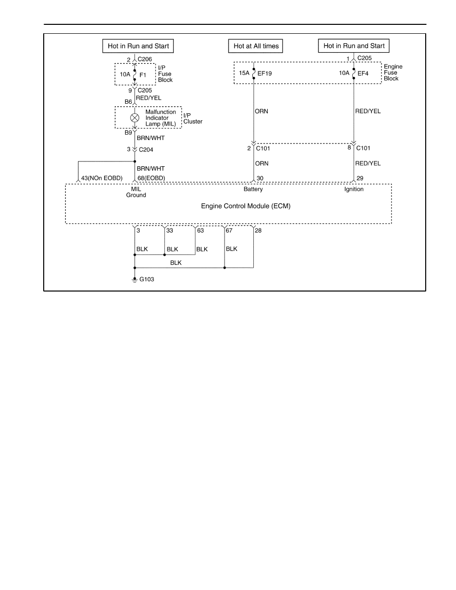
1F – 30 ENGINE CONTROLS
DAEWOO M-150 BL2
MAA1F030
NO MALFUNCTION INDICATOR LAMP
Circuit Description
When the ignition is turned ON, the Malfunction Indica-
tor Lamp (MIL) will be turned ON and remain ON until
the engine is running, if no Diagnostic Trouble Codes
(DTCs) are stored. Battery voltage is supplied through
the ignition switch directly to the MIL telltale. The Engine
Control Module (ECM) controls the MIL by providing a
ground path through the MIL control circuit to turn ON
the MIL.
Diagnostic Aids
An open ignition F16 fuse will cause the entire cluster to
be inoperative.
Check the battery and ignition feed circuits for poor con-
nections if the MIL is intermittent.
Any circuitry, that is suspected as causing an intermit-
tent complaint, should be thoroughly checked for
backed-out terminals, improper mating, broken locks,
improperly formed or damaged terminals, poor terminal-
to-wiring connections or physical damage to the wiring
harness.

ENGINE CONTROLS 1F – 31
DAEWOO M-150 BL2
No Malfunction Indicator Lamp
Step
Action
Value(s)
Yes
No
1
Attempt to start the engine.
Does the engine start?
–
Go to Step 2
Go to “Engine
Cranks But
Will Not Run”
2
1. Turn the ignition OFF.
2. Disconnect the engine control module (ECM)
connector.
3. Turn the ignition ON.
4. Connect a test light between terminal 68 of ECM
connector and ground.
Is the test light on?
–
Go to Step 3
Go to Step 6
3
Check terminals for damage or poor connection.
Does any problem found?
–
Go to Step 5
Go to Step 4
4
Replace ECM
Is the repair complete?
–
Go to “On
Board
Diagnostic
System Check”
–
5
Repair any damaged terminals or poor connection.
Is the repair complete?
–
Go to “On
Board
Diagnostic
System Check”
–
6
Check the fuse F1.
Is the fuse blown?
–
Go to Step 7
Go to Step 8
7
1. Check for a short to ground in the circuit and
repair as needed.
2. Replace the blown fuse.
Is the repair complete?
–
Go to “On
Board
Diagnostic
System Check”
–
8
1. Check for an open circuit between fuse F16 and
terminal 68 of ECM connector and repair as
needed.
2. Check the MIL bulb and replace if blown.
Is the repair complete?
–
Go to “On
Board
Diagnostic
System Check”
–

1F – 32 ENGINE CONTROLS
DAEWOO M-150 BL2
MAA1F030
MALFUNCTION INDICATOR LAMP ON STEADY
Circuit Description
When the ignition is turned ON, the Malfunction Indica-
tor Lamp (MIL) will be turned ON and remain ON until
the engine is running, if no Diagnostic Trouble Codes
(DTCs) are stored. Battery voltage is supplied through
the ignition switch directly to the MIL telltale. The Engine
Control Module (ECM) controls the MIL by providing a
ground path through the MIL control circuit to turn ON
the MIL.

ENGINE CONTROLS 1F – 33
DAEWOO M-150 BL2
Malfunction Indicator Lamp On Steady
Step
Action
Value(s)
Yes
No
1
Perform an Euro On-Board Diagnostic (EOBD)
System Check.
Is the check complete.
–
Go to Step 2
Go to “Euro
On-Board
Diagnostic
System Check”
2
1. Turn the ignition OFF.
2. Install the scan tool.
3. Command the Malfunction Indicator Lamp (MIL)
on and off.
Does the MIL turn on and off when commanded?
–
Go to Step 7
Go to Step 3
3
1. Turn the ignition OFF.
2. Disconnect the engine control module (ECM)
connector.
3. Turn the ignition ON.
Is the MIL off?
–
Go to Step 6
Go to Step 4
4
Check the MIL control circuit for a short to ground
and repair as needed.
Is a repair necessary?
–
Go to Step 7
Go to Step 5
5
Replace the instrument panel cluster. Refer to
Section 9E, Instrumentation/Driver Information.
Is the repair complete?
–
Go to Step 7
–
6
Replace the ECM.
Is the repair complete?
–
Go to Step 7
–
7
1. Using the scan tool, clear the Diagnostic Trouble
Codes(DTCs).
2. Attempt to start the engine.
Does the engine start and continue to run?
–
Go to Step 8
Go to Step 1
8
Allow the engine to idle until normal operating
temperature is reached.
Check if any DTCs are set.
Are any DTCs displayed that have not been
diagnosed?
–
Go to applicable
DTC table
System OK

1F – 34 ENGINE CONTROLS
DAEWOO M-150 BL2
FUEL SYSTEM DIAGNOSIS
Circuit Description
The fuel pump is an in-tank type mounted to a fuel send-
er assembly. The fuel pump will remain on as long as the
engine is cranking or running and the Engine Control
Module (ECM) is receiving reference pulses from the
crankshaft position (CKP) sensor. If there are no refer-
ence pulses, the ECM will turn off the fuel pump two sec-
onds after the ignition switch is turned ON or two
seconds after the engine stops running. The fuel pump
delivers fuel to the fuel rail and the fuel injectors, where
the fuel system pressure is controlled from 380 kPa (55
psi) by the fuel pressure regulator. The excess fuel is re-
turned to the fuel tank.
Caution: The fuel system is under pressure. To
avoid fuel spillage and the risk of personal injury or
fire, it is necessary to relieve the fuel system pres-
sure before disconnecting the fuel lines.
Caution: Do not pinch or restrict nylon fuel lines.
Damage to the lines could cause a fuel leak, result-
ing in possible fire or personal injury.
Fuel Pressure Relief Procedure
1. Remove the fuel cap.
2. Remove the fuel pump fuse EF23 from the engine
fuse block.
3. Start the engine and allow the engine to stall.
4. Crank the engine for an additional 10 seconds.
Fuel System Pressure Test
ÁÁÁÁ
ÁÁÁÁ
Step
ÁÁÁÁÁÁÁÁÁÁÁÁÁÁÁÁÁ
ÁÁÁÁÁÁÁÁÁÁÁÁÁÁÁÁÁ
Action
ÁÁÁÁÁ
ÁÁÁÁÁ
Value(s)
ÁÁÁÁÁÁÁ
ÁÁÁÁÁÁÁ
Yes
ÁÁÁÁÁÁ
ÁÁÁÁÁÁ
No
ÁÁÁÁ
ÁÁÁÁ
ÁÁÁÁ
ÁÁÁÁ
ÁÁÁÁ
1
ÁÁÁÁÁÁÁÁÁÁÁÁÁÁÁÁÁ
ÁÁÁÁÁÁÁÁÁÁÁÁÁÁÁÁÁ
ÁÁÁÁÁÁÁÁÁÁÁÁÁÁÁÁÁ
ÁÁÁÁÁÁÁÁÁÁÁÁÁÁÁÁÁ
ÁÁÁÁÁÁÁÁÁÁÁÁÁÁÁÁÁ
1. Relieve the fuel system pressure.
2. Install a fuel pressure gauge.
3. Turn the ignition ON.
Is the fuel pressure around the values specified and
holding steady?
ÁÁÁÁÁ
ÁÁÁÁÁ
ÁÁÁÁÁ
ÁÁÁÁÁ
ÁÁÁÁÁ
380 kPa
(55 psi)
ÁÁÁÁÁÁÁ
ÁÁÁÁÁÁÁ
ÁÁÁÁÁÁÁ
ÁÁÁÁÁÁÁ
ÁÁÁÁÁÁÁ
System OK
ÁÁÁÁÁÁ
ÁÁÁÁÁÁ
ÁÁÁÁÁÁ
ÁÁÁÁÁÁ
ÁÁÁÁÁÁ
Go to Step 2
ÁÁÁÁ
ÁÁÁÁ
ÁÁÁÁ
ÁÁÁÁ
ÁÁÁÁ
2
ÁÁÁÁÁÁÁÁÁÁÁÁÁÁÁÁÁ
ÁÁÁÁÁÁÁÁÁÁÁÁÁÁÁÁÁ
ÁÁÁÁÁÁÁÁÁÁÁÁÁÁÁÁÁ
ÁÁÁÁÁÁÁÁÁÁÁÁÁÁÁÁÁ
ÁÁÁÁÁÁÁÁÁÁÁÁÁÁÁÁÁ
1. Relieve the fuel system pressure.
2. Install a fuel pressure gauge.
3. Turn the ignition ON.
Is the fuel pressure around the values specified but
not holding steady?
ÁÁÁÁÁ
ÁÁÁÁÁ
ÁÁÁÁÁ
ÁÁÁÁÁ
ÁÁÁÁÁ
380 kPa
(55 psi)
ÁÁÁÁÁÁÁ
ÁÁÁÁÁÁÁ
ÁÁÁÁÁÁÁ
ÁÁÁÁÁÁÁ
ÁÁÁÁÁÁÁ
Go to Step 13
ÁÁÁÁÁÁ
ÁÁÁÁÁÁ
ÁÁÁÁÁÁ
ÁÁÁÁÁÁ
ÁÁÁÁÁÁ
Go to Step 3
ÁÁÁÁ
ÁÁÁÁ
ÁÁÁÁ
3
ÁÁÁÁÁÁÁÁÁÁÁÁÁÁÁÁÁ
ÁÁÁÁÁÁÁÁÁÁÁÁÁÁÁÁÁ
ÁÁÁÁÁÁÁÁÁÁÁÁÁÁÁÁÁ
Inspect the fuel lines for a leak.
Is the problem found?
ÁÁÁÁÁ
ÁÁÁÁÁ
ÁÁÁÁÁ
–
ÁÁÁÁÁÁÁ
ÁÁÁÁÁÁÁ
ÁÁÁÁÁÁÁ
Go to Step 4
ÁÁÁÁÁÁ
ÁÁÁÁÁÁ
ÁÁÁÁÁÁ
Go to Step 5
ÁÁÁÁ
ÁÁÁÁ
ÁÁÁÁ
ÁÁÁÁ
ÁÁÁÁ
4
ÁÁÁÁÁÁÁÁÁÁÁÁÁÁÁÁÁ
ÁÁÁÁÁÁÁÁÁÁÁÁÁÁÁÁÁ
ÁÁÁÁÁÁÁÁÁÁÁÁÁÁÁÁÁ
ÁÁÁÁÁÁÁÁÁÁÁÁÁÁÁÁÁ
ÁÁÁÁÁÁÁÁÁÁÁÁÁÁÁÁÁ
1. Replace the fuel line(s) as needed.
2. Install a fuel pressure gauge.
3. Turn the ignition ON.
Is the fuel pressure around the values specified and
holding steady?
ÁÁÁÁÁ
ÁÁÁÁÁ
ÁÁÁÁÁ
ÁÁÁÁÁ
ÁÁÁÁÁ
380 kPa
(55 psi)
ÁÁÁÁÁÁÁ
ÁÁÁÁÁÁÁ
ÁÁÁÁÁÁÁ
ÁÁÁÁÁÁÁ
ÁÁÁÁÁÁÁ
System OK
ÁÁÁÁÁÁ
ÁÁÁÁÁÁ
ÁÁÁÁÁÁ
ÁÁÁÁÁÁ
ÁÁÁÁÁÁ
–
ÁÁÁÁ
ÁÁÁÁ
ÁÁÁÁ
ÁÁÁÁ
ÁÁÁÁ
5
ÁÁÁÁÁÁÁÁÁÁÁÁÁÁÁÁÁ
ÁÁÁÁÁÁÁÁÁÁÁÁÁÁÁÁÁ
ÁÁÁÁÁÁÁÁÁÁÁÁÁÁÁÁÁ
ÁÁÁÁÁÁÁÁÁÁÁÁÁÁÁÁÁ
ÁÁÁÁÁÁÁÁÁÁÁÁÁÁÁÁÁ
1. Remove the fuel pump assembly.
2. With the fuel pump under pressure, inspect the
fuel pump coupling hoses for leaking.
Is the problem found?
ÁÁÁÁÁ
ÁÁÁÁÁ
ÁÁÁÁÁ
ÁÁÁÁÁ
ÁÁÁÁÁ
–
ÁÁÁÁÁÁÁ
ÁÁÁÁÁÁÁ
ÁÁÁÁÁÁÁ
ÁÁÁÁÁÁÁ
ÁÁÁÁÁÁÁ
Go to Step 6
ÁÁÁÁÁÁ
ÁÁÁÁÁÁ
ÁÁÁÁÁÁ
ÁÁÁÁÁÁ
ÁÁÁÁÁÁ
Go to Step 7
ÁÁÁÁ
ÁÁÁÁ
ÁÁÁÁ
ÁÁÁÁ
ÁÁÁÁ
ÁÁÁÁ
6
ÁÁÁÁÁÁÁÁÁÁÁÁÁÁÁÁÁ
ÁÁÁÁÁÁÁÁÁÁÁÁÁÁÁÁÁ
ÁÁÁÁÁÁÁÁÁÁÁÁÁÁÁÁÁ
ÁÁÁÁÁÁÁÁÁÁÁÁÁÁÁÁÁ
ÁÁÁÁÁÁÁÁÁÁÁÁÁÁÁÁÁ
ÁÁÁÁÁÁÁÁÁÁÁÁÁÁÁÁÁ
1. Tighten or replace the fuel pump coupling hoses
as needed.
2. Install a fuel pressure gauge.
3. Turn the ignition ON.
Is the fuel pressure around the values specified and
holding steady?
ÁÁÁÁÁ
ÁÁÁÁÁ
ÁÁÁÁÁ
ÁÁÁÁÁ
ÁÁÁÁÁ
ÁÁÁÁÁ
380 kPa
(55 psi)
ÁÁÁÁÁÁÁ
ÁÁÁÁÁÁÁ
ÁÁÁÁÁÁÁ
ÁÁÁÁÁÁÁ
ÁÁÁÁÁÁÁ
ÁÁÁÁÁÁÁ
System OK
ÁÁÁÁÁÁ
ÁÁÁÁÁÁ
ÁÁÁÁÁÁ
ÁÁÁÁÁÁ
ÁÁÁÁÁÁ
ÁÁÁÁÁÁ
Go to Step 8
ÁÁÁÁ
ÁÁÁÁ
ÁÁÁÁ
7
ÁÁÁÁÁÁÁÁÁÁÁÁÁÁÁÁÁ
ÁÁÁÁÁÁÁÁÁÁÁÁÁÁÁÁÁ
ÁÁÁÁÁÁÁÁÁÁÁÁÁÁÁÁÁ
With the fuel system under pressure, inspect the fuel
return outlet for leaking.
Is the problem found?
ÁÁÁÁÁ
ÁÁÁÁÁ
ÁÁÁÁÁ
–
ÁÁÁÁÁÁÁ
ÁÁÁÁÁÁÁ
ÁÁÁÁÁÁÁ
Go to Step 8
ÁÁÁÁÁÁ
ÁÁÁÁÁÁ
ÁÁÁÁÁÁ
Go to Step 9

ENGINE CONTROLS 1F – 35
DAEWOO M-150 BL2
Fuel System Pressure Test (Cont’d)
ÁÁÁÁ
ÁÁÁÁ
Step
ÁÁÁÁÁÁÁÁÁÁÁÁÁÁÁÁÁ
ÁÁÁÁÁÁÁÁÁÁÁÁÁÁÁÁÁ
Action
ÁÁÁÁÁ
ÁÁÁÁÁ
Value(s)
ÁÁÁÁÁÁÁ
ÁÁÁÁÁÁÁ
Yes
ÁÁÁÁÁÁ
ÁÁÁÁÁÁ
No
ÁÁÁÁ
ÁÁÁÁ
ÁÁÁÁ
ÁÁÁÁ
ÁÁÁÁ
8
ÁÁÁÁÁÁÁÁÁÁÁÁÁÁÁÁÁ
ÁÁÁÁÁÁÁÁÁÁÁÁÁÁÁÁÁ
ÁÁÁÁÁÁÁÁÁÁÁÁÁÁÁÁÁ
ÁÁÁÁÁÁÁÁÁÁÁÁÁÁÁÁÁ
ÁÁÁÁÁÁÁÁÁÁÁÁÁÁÁÁÁ
1. Replace the fuel pressure regulator.
2. Install a fuel pressure gauge.
3. Turn the ignition ON.
Is the fuel pressure around the values specified and
holding steady?
ÁÁÁÁÁ
ÁÁÁÁÁ
ÁÁÁÁÁ
ÁÁÁÁÁ
ÁÁÁÁÁ
380 kPa
(55 psi)
ÁÁÁÁÁÁÁ
ÁÁÁÁÁÁÁ
ÁÁÁÁÁÁÁ
ÁÁÁÁÁÁÁ
ÁÁÁÁÁÁÁ
System OK
ÁÁÁÁÁÁ
ÁÁÁÁÁÁ
ÁÁÁÁÁÁ
ÁÁÁÁÁÁ
ÁÁÁÁÁÁ
–
ÁÁÁÁ
ÁÁÁÁ
ÁÁÁÁ
ÁÁÁÁ
9
ÁÁÁÁÁÁÁÁÁÁÁÁÁÁÁÁÁ
ÁÁÁÁÁÁÁÁÁÁÁÁÁÁÁÁÁ
ÁÁÁÁÁÁÁÁÁÁÁÁÁÁÁÁÁ
ÁÁÁÁÁÁÁÁÁÁÁÁÁÁÁÁÁ
With the fuel system under pressure, inspect the fuel
return inlet for leaking.
Is the problem found?
ÁÁÁÁÁ
ÁÁÁÁÁ
ÁÁÁÁÁ
ÁÁÁÁÁ
–
ÁÁÁÁÁÁÁ
ÁÁÁÁÁÁÁ
ÁÁÁÁÁÁÁ
ÁÁÁÁÁÁÁ
Go to Step 10
ÁÁÁÁÁÁ
ÁÁÁÁÁÁ
ÁÁÁÁÁÁ
ÁÁÁÁÁÁ
Go to Step 11
ÁÁÁÁ
ÁÁÁÁ
ÁÁÁÁ
ÁÁÁÁ
ÁÁÁÁ
10
ÁÁÁÁÁÁÁÁÁÁÁÁÁÁÁÁÁ
ÁÁÁÁÁÁÁÁÁÁÁÁÁÁÁÁÁ
ÁÁÁÁÁÁÁÁÁÁÁÁÁÁÁÁÁ
ÁÁÁÁÁÁÁÁÁÁÁÁÁÁÁÁÁ
ÁÁÁÁÁÁÁÁÁÁÁÁÁÁÁÁÁ
1. Replace the fuel pump assembly.
2. Install a fuel pressure gauge.
3. Turn the ignition ON.
Is the fuel pressure around the values specified and
holding steady?
ÁÁÁÁÁ
ÁÁÁÁÁ
ÁÁÁÁÁ
ÁÁÁÁÁ
ÁÁÁÁÁ
380 kPa
(55 psi)
ÁÁÁÁÁÁÁ
ÁÁÁÁÁÁÁ
ÁÁÁÁÁÁÁ
ÁÁÁÁÁÁÁ
ÁÁÁÁÁÁÁ
System OK
ÁÁÁÁÁÁ
ÁÁÁÁÁÁ
ÁÁÁÁÁÁ
ÁÁÁÁÁÁ
ÁÁÁÁÁÁ
–
ÁÁÁÁ
ÁÁÁÁ
ÁÁÁÁ
ÁÁÁÁ
ÁÁÁÁ
11
ÁÁÁÁÁÁÁÁÁÁÁÁÁÁÁÁÁ
ÁÁÁÁÁÁÁÁÁÁÁÁÁÁÁÁÁ
ÁÁÁÁÁÁÁÁÁÁÁÁÁÁÁÁÁ
ÁÁÁÁÁÁÁÁÁÁÁÁÁÁÁÁÁ
ÁÁÁÁÁÁÁÁÁÁÁÁÁÁÁÁÁ
1. Remove the fuel rail and the fuel injectors as an
assembly.
2. With the fuel system under pressure, inspect all
of the fuel injectors for leaking.
Is the problem found?
ÁÁÁÁÁ
ÁÁÁÁÁ
ÁÁÁÁÁ
ÁÁÁÁÁ
ÁÁÁÁÁ
–
ÁÁÁÁÁÁÁ
ÁÁÁÁÁÁÁ
ÁÁÁÁÁÁÁ
ÁÁÁÁÁÁÁ
ÁÁÁÁÁÁÁ
Go to Step 12
ÁÁÁÁÁÁ
ÁÁÁÁÁÁ
ÁÁÁÁÁÁ
ÁÁÁÁÁÁ
ÁÁÁÁÁÁ
–
ÁÁÁÁ
ÁÁÁÁ
ÁÁÁÁ
ÁÁÁÁ
ÁÁÁÁ
12
ÁÁÁÁÁÁÁÁÁÁÁÁÁÁÁÁÁ
ÁÁÁÁÁÁÁÁÁÁÁÁÁÁÁÁÁ
ÁÁÁÁÁÁÁÁÁÁÁÁÁÁÁÁÁ
ÁÁÁÁÁÁÁÁÁÁÁÁÁÁÁÁÁ
ÁÁÁÁÁÁÁÁÁÁÁÁÁÁÁÁÁ
1. Replace the leaking fuel injector(s).
2. Install a fuel pressure gauge.
3. Turn the ignition ON.
Is the fuel pressure around the values specified and
holding steady?
ÁÁÁÁÁ
ÁÁÁÁÁ
ÁÁÁÁÁ
ÁÁÁÁÁ
ÁÁÁÁÁ
380 kPa
(55 psi)
ÁÁÁÁÁÁÁ
ÁÁÁÁÁÁÁ
ÁÁÁÁÁÁÁ
ÁÁÁÁÁÁÁ
ÁÁÁÁÁÁÁ
System OK
ÁÁÁÁÁÁ
ÁÁÁÁÁÁ
ÁÁÁÁÁÁ
ÁÁÁÁÁÁ
ÁÁÁÁÁÁ
–
ÁÁÁÁ
ÁÁÁÁ
ÁÁÁÁ
ÁÁÁÁ
ÁÁÁÁ
ÁÁÁÁ
13
ÁÁÁÁÁÁÁÁÁÁÁÁÁÁÁÁÁ
ÁÁÁÁÁÁÁÁÁÁÁÁÁÁÁÁÁ
ÁÁÁÁÁÁÁÁÁÁÁÁÁÁÁÁÁ
ÁÁÁÁÁÁÁÁÁÁÁÁÁÁÁÁÁ
ÁÁÁÁÁÁÁÁÁÁÁÁÁÁÁÁÁ
ÁÁÁÁÁÁÁÁÁÁÁÁÁÁÁÁÁ
1. Replace the fuel pressure regulator.
2. Start the engine.
3. Allow the engine to idle.
Is the fuel pressure around the values specified and
holding steady?
ÁÁÁÁÁ
ÁÁÁÁÁ
ÁÁÁÁÁ
ÁÁÁÁÁ
ÁÁÁÁÁ
ÁÁÁÁÁ
380 kPa
(55 psi)
ÁÁÁÁÁÁÁ
ÁÁÁÁÁÁÁ
ÁÁÁÁÁÁÁ
ÁÁÁÁÁÁÁ
ÁÁÁÁÁÁÁ
ÁÁÁÁÁÁÁ
System OK
ÁÁÁÁÁÁ
ÁÁÁÁÁÁ
ÁÁÁÁÁÁ
ÁÁÁÁÁÁ
ÁÁÁÁÁÁ
ÁÁÁÁÁÁ
–
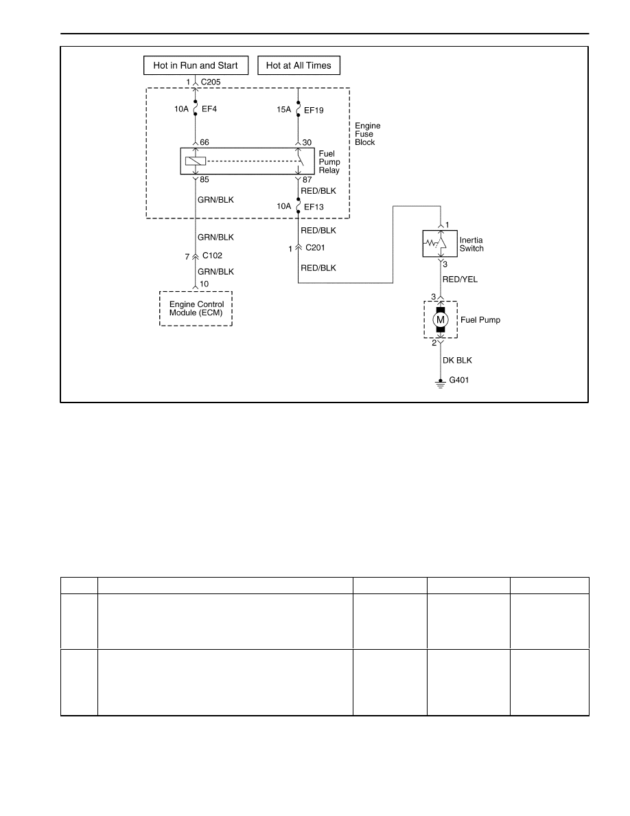
1F – 36 ENGINE CONTROLS
DAEWOO M-150 BL2
MAA1F040
FUEL PUMP RELAY CIRCUIT CHECK
Circuit Description
When the ignition switch is turned ON, the Engine Con-
trol Module (ECM) will supply battery voltage to activate
the fuel pump relay and run the in-tank fuel pump. The
fuel pump will operate as long as the engine is cranking
or running and the ECM is receiving ignition reference
pulses.
If there are no reference pulses, the ECM will shut off
the fuel pump within 2 seconds after the ignition switch
is turned ON.
Diagnostic Aids
An intermittent problem may be caused by a poor con-
nection, rubbed through wire insulation, or a broken wire
inside the insulation.
Fuel Pump Relay Circuit Check
Step
Action
Value(s)
Yes
No
1
1. Turn the ignition OFF for 10 seconds.
2. Turn the ignition ON.
3. Listen for in-tank fuel pump operation.
Does the fuel pump operate for the time specified?
2 sec
System OK
Go to Step 2
2
1. Turn the ignition OFF.
2. Connect battery positive to fuel pump test
connect.
3. Listen for in-tank fuel pump operation.
Does the fuel pump operate?
–
Go to Step 4
Go to Step 3

ENGINE CONTROLS 1F – 37
DAEWOO M-150 BL2
Fuel Pump Relay Circuit Check (Cont’d)
Step
Action
Value(s)
Yes
No
3
1. Check for an open circuit between fuel pump test
connector and ground G401, and repair as
needed.
2. Check for the fuel cut-off switch and reset or
replace the fuel cut off switch.
Is the repair complete?
–
System OK
Go to Step 4
4
1. Turn the ignition OFF.
2. Disconnect the fuel pump relay.
3. Connect a test light between the fuel pump relay
connector terminal 66 and battery positive.
4. Turn the ignition ON.
Is the test light on?
–
Go to Step 6
Go to Step 5
5
Check for an open circuit between terminal 66 of fuel
pump relay and battery positive and repair as
needed.
Is the repair complete?
–
System OK
–
6
1. Turn the ignition OFF.
2. Connect a test light between the fuel pump relay
connector terminal 85 and ground.
3. Turn the ignition ON.
Is the test light on?
2 sec
Go to Step 8
Go to Step 7
7
Check for an open circuit between terminal 85 of fuel
pump relay and terminal 10 of ECM, and repair as
needed.
Is the repair complete?
–
System OK
–
8
1. Turn the ignition OFF.
2. Connect a test light between the fuel pump relay
connector terminal 30 and ground.
Is the test light on?
–
Go to Step 10
Go to Step 9
9
1. Check the fuse EF19, if blown, repair short circuit
between fuel pump relay 30 terminal.
2. Replace the fuse as needed.
3. Repair an open circuit as needed.
Is the repair complete?
–
System OK
–
10
1. Turn the ignition OFF.
2. Measure the resistance between following
terminals:
D
Terminal 87 of fuel pump relay and terminal 1
of the fuel cut-off switch(or terminal 1 of
connector C201).
Does the resistance within the value specified.
0
Ω
Go to Step 12
Go to Step 11
11
Repair an open circuit as needed.
Is the repair complete?
–
System OK
–
12
Replace the fuel pump relay.
Is the repair complete?
–
System OK
Go to Step 13
13
Replace the ECM.
Is the repair complete?
–
System OK
–
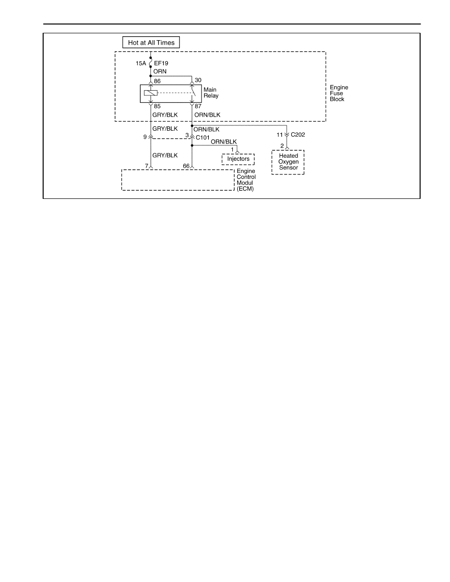
1F – 38 ENGINE CONTROLS
DAEWOO M-150 BL2
MAA1F050
MAIN RELAY CIRCUIT CHECK
Circuit Description
When the ignition is turned On or to the START position,
the main relay is energized. The main relay then supply
voltage to the engine fuse block fuse EF25 and EF26.
The Electronic Ignition (EI) system ignition coil is sup-
plied voltage through the engine fuse block fuse EF26.
The fuel injectors are supplied voltage through the en-
gine fuse block fuse EF25.
Diagnostic Aids
D
An intermittent problem may be caused by a poor
connection, rubbed through wire insulation, or a bro-
ken wire inside the insulation.
D
A fault main relay will cause a no start condition.
There will be no voltage supplied to the EI system
ignition coil, or the fuel injectors. Without voltage sup-
plied to these components, they will not operate.

ENGINE CONTROLS 1F – 39
DAEWOO M-150 BL2
Main Relay Circuit Check
Step
Action
Value(s)
Yes
No
1
1. Turn the ignition OFF.
2. Disconnect the engine fuse block fuse EF26.
3. Turn the ignition ON.
4. With a test light connected to the ground, probe
the fuse terminals nearest the main relay for fuse
EF19.
Is the light on at both terminal?
–
System OK
Go to Step 2
2
Is the light on at only one terminal?
–
Go to Step 3
Go to Step 4
3
Repair the open in the wiring between the main relay
connector terminal 30 and the fuse EF19 as needed.
Is the repair complete?
–
System OK
–
4
1. Turn the ignition OFF.
2. Remove the main relay.
3. Turn the ignition ON.
4. With a test light connected to the ground, probe
the main relay terminals 85 and 30.
Is the light on at both terminals.
–
Go to Step 8
Go to Step 5
5
1. Turn the ignition OFF.
2. Check engine fuse block fuse EF19.
Is one or both fuse blown?
–
Go to Step 6
Go to Step 7
6
1. Repair short circuit between terminal 87 of main
relay and heated oxygen sensor
2. Replace fuse EF19.
Is the repair complete?
–
System OK
–
7
Repair open circuit between terminal 30 of main
relay and fuse EF19.
Is the repair complete?
–
System OK
Go to Step 8
8
1. Turn the ignition OFF.
2. Measure the resistance between following
terminals.
D
Terminal 86 of main relay and ground.
D
Terminal 87 of main relay and ground.
Is the resistance within the specified value
0
Ω
Go to Step 10
Go to Step 9
9
Repair open circuit.
Is the repair complete?
–
System OK
–
10
Replace the main relay.
Is the repair complete?
–
System OK
–
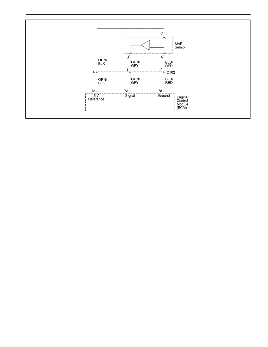
1F – 40 ENGINE CONTROLS
DAEWOO M-150 BL2
MAA1F060
MANIFOLD ABSOLUTE PRESSURE CHECK
Circuit Description
The Manifold Absolute Pressure (MAP) sensor measure
the changes in the intake manifold pressure which result
from engine load (intake manifold vacuum) and rpm
changes. The MAP sensor converts these changes into
voltage output. The Engine Control Module (ECM) send
a 5-volt reference voltage to the MAP sensor. As the in-
take manifold pressure changes, the output voltage of
MAP sensor also changes. A low voltage (high vacuum)
output of 1 to 1.5 volts is present at idle. A high voltage
(low vacuum) output of 4.5 to 5.0 volts is present at wide
open throttle. The MAP sensor is also used under cer-
tain conditions to measure barometric attitude changes.
The ECM uses the MAP sensor for the delivery and igni-
tion timing changes.

ENGINE CONTROLS 1F – 41
DAEWOO M-150 BL2
Manifold Absolute Pressure Check
Step
Action
Value(s)
Yes
No
1
1. Turn the ignition OFF.
2. Connect a scan tool to the Data Link Connector
(DLC).
3. Turn the ignition ON.
4. Compare the Manifold Absolute Pressure (MAP)
sensor voltage reading from scanner with that
from known good vehicle.
Is the difference in the two voltage reading less than
the value specified?
0.4 V
Go to Step 2
Go to Step 5
2
1. Turn the ignition OFF.
2. Connect a scan tool to the DLC.
3. Disconnect the MAP sensor vacuum line.
4. Connect a hand vacuum pump to the Map sensor.
5. Turn the ignition ON.
6. Note the MAP sensor voltage.
7. Apply 34kPa (10 in. Hg) of vacuum to the Map
sensor and note the voltage change.
Is the difference in voltage readings more than the
value specified?
1.5 V
System OK
Go to Step 3
3
Inspect the MAP sensor connector terminals.
Is the problem found.
–
Go to Step 4
Go to Step 5
4
Repair the MAP sensor connector terminals as
needed.
Is the repair complete?
–
System OK
–
5
Replace the MAP sensor.
Is the repair complete?
–
System OK
–
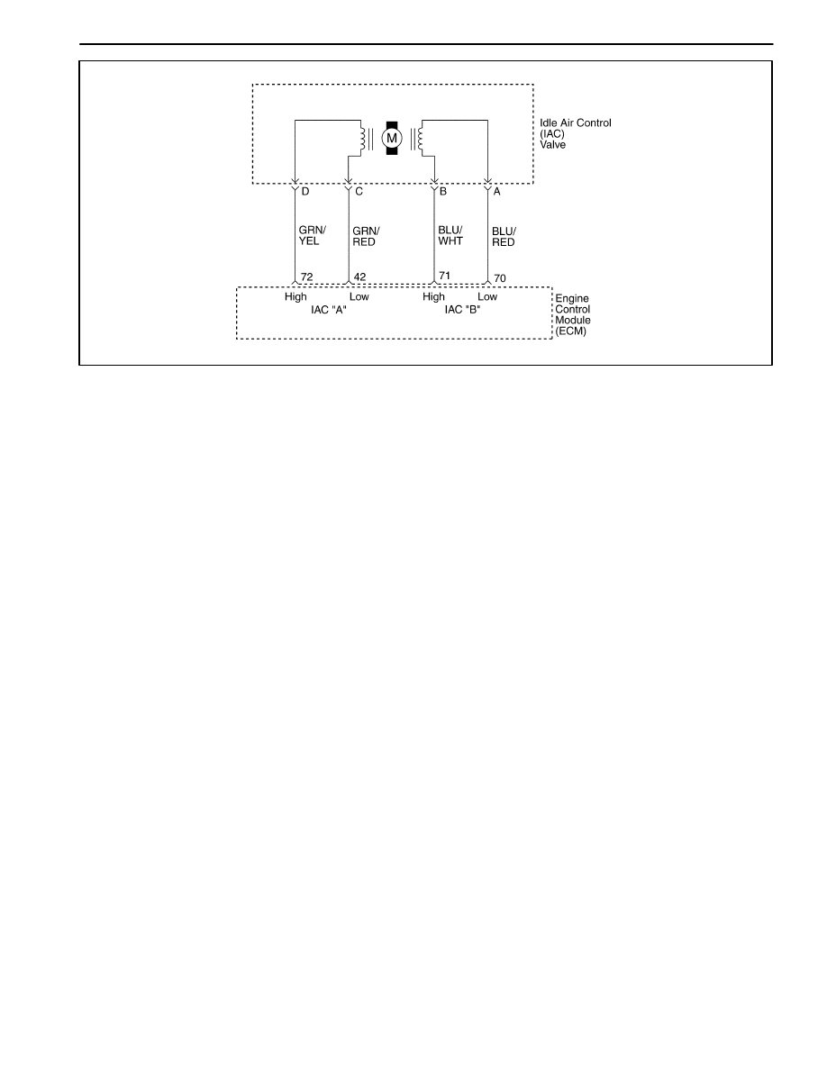
1F – 42 ENGINE CONTROLS
DAEWOO M-150 BL2
MAA1F070
IDLE AIR CONTROL SYSTEM CHECK
Circuit Description
The Engine Control Module (ECM) controls the engine
idle speed with the Idle Air Control (IAC) valve. To in-
crease the idle speed, the ECM pulls the IAC pintle
away from its seat, allowing more air to pass by the
throttle body. To decrease the idle speed, it extends the
IAC valve pintle toward its seat, reducing bypass air
flow. A scan tool will read the ECM commands to the
IAC valve in counts. The higher counts indicate more air
bypass (higher idle). The lower counts indicate less air is
allowed to bypass (lower idle).
Diagnostic Aids
If the idle is too high, stop the engine. Fully extend the
Idle Air Control (IAC) valve with a IAC driver. Start the
engine. If the idle speed is above 950 rpm, locate and
repair the vacuum leak. Also, check for a binding throttle
plate or throttle linkage or an incorrect base idle setting.
Idle Air Control Valve Reset Procedure
Whenever the battery cable or the Engine Control Mod-
ule (ECM) connector or the ECM fuse EF6 is discon-
nected or replaced, the following idle learn procedure
must be performed:
1.
Turn the ignition ON for 5 seconds.
2.
Turn the ignition OFF for 10 seconds.
3.
Turn the ignition ON for 5 seconds.
4.
Start the engine in park/neutral.
5.
Allow the engine to run until the engine coolant is
above 85
_
C (185
_
F ).
6.
Turn the A/C ON for 10 seconds, if equipped.
7.
Turn the A/C OFF for 10 seconds, if equipped.
8.
If the vehicle is equipped with an automatic trans-
axle, apply the parking brake. While pressing the
brake pedal, place the transaxle in D (drive).
9.
Turn the A/C ON for 10 seconds, if equipped.
10. Turn the A/C OFF for 10 seconds, if equipped.
11. Turn the ignition OFF. The idle learn procedure is
complete.

ENGINE CONTROLS 1F – 43
DAEWOO M-150 BL2
Idle Air Control System Check
Step
Action
Value(s)
Yes
No
1
Perform an Euro On-Board Diagnostic (EOBD)
system check.
Was the check performed?
–
Go to Step 2
Go to “Euro
On-Board
Diagnostic
System Check”
2
1. Turn the ignition OFF.
2. Remove Idle Air Control (IAC) valve.
3. Inspect the IAC passages for restrictions.
Is the problem found?
–
Go to Step 3
Go to Step 4
3
Clean the IAC passages.
Is the repair complete?
–
System OK
–
4
Measure the resistance between following terminals
of IAC valve.
D
Terminal A and B
D
Terminal C and D
Does the resistance equal to the value specified?
40–80
Ω
Go to Step 6
Go to Step 5
5
Replace the IAC valve.
Is the repair complete?
–
System OK
–
6
1. Disconnect the Engine control Module (ECM)
connector.
2. Check for an open or short in the wires between
following terminals.
D
Terminal A of IAC valve connector and terminal
70 of ECM connector
D
Terminal B of IAC valve connector and terminal
71 of ECM connector
D
Terminal C of IAC valve connector and terminal
42 of ECM connector
D
Terminal D of IAC valve connector and terminal
72 of ECM connector
Is the problem found?
–
Go to Step 8
Go to Step 7
7
Repair an open or short circuit as needed.
Is the repair complete?
–
System OK
–
8
Inspect the IAC connector terminals and the ECM
connector terminals.
Is the problem found?
–
Go to Step 9
Go to Step 10
9
Repair or replace the throttle body assembly and/or
ECM connector terminals as needed.
Is the repair complete?
–
System OK
–
10
Replace the ECM.
Is the repair complete?
–
System OK
–
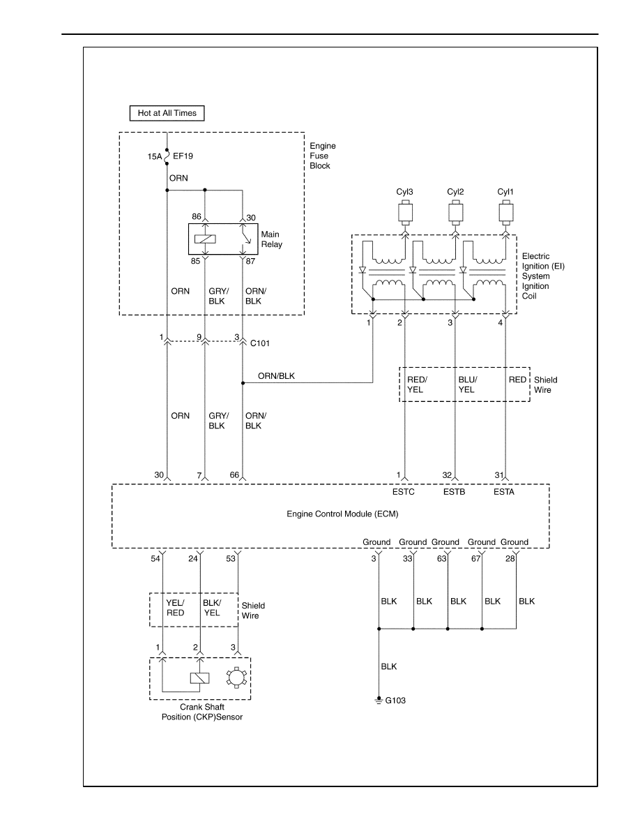
1F – 44 ENGINE CONTROLS
DAEWOO M-150 BL2
MAA1F080
IG
NI
T
IO
N
SYST
EM
C
H
ECK

ENGINE CONTROLS 1F – 45
DAEWOO M-150 BL2
IGNITION SYSTEM CHECK
Circuit Description
The Electronic Ignition (EI) system uses a waste spark
method of spark distribution. In this type of EI system,
the Crankshaft Position (CKP) sensor is mounted to the
oil pump near a slotted wheel that is a part of the crank-
shaft pulley. The CKP sensor sends reference pulses to
the Engine Control Module (ECM). The ECM then trig-
gers the EI system ignition coil. Each cylinder is individu-
al with coil per cylinder in sequence.
This leaves the remainder of the high voltage to be used
to fire the spark plug in the cylinder on its compression
stroke. Since the CKP sensor is in a fixed position, tim-
ing adjustments are not possible or needed.
Ignition System Check
Caution: Use only electrically insulated pliers when
handling ignition wires with the engine running to
prevent an electrical shock.
Step
Action
Value(s)
Yes
No
1
1. Remove the spark plugs.
2. Inspect for wet spark plugs, cracks, wear,
improper gap, burned electrodes, or heavy
deposits.
3. Replace the spark plugs as needed.
Is the repair complete?
–
System OK
Go to Step 2
2
Check for the presence of spark from all of the
ignition wires while cranking the engine.
Is spark present from all of the ignition wires?
–
System OK
Go to Step 3
3
1. Measure the resistance of the ignition wires.
2. Replace any ignition wire(s) with a resistance
above the value specified.
3. Check for the presence of spark from all of the
ignition wires.
Is spark present from all of the ignition wires?
30000
Ω
System OK
Go to Step 4
4
Is spark present from at least one of the ignition
wires, but not all of the ignition wires?
Go to Step 5
Go to Step 12
5
1. Turn the ignition OFF.
2. Disconnect the Electronic Ignition (EI) system
ignition coil connector.
3. While cranking the engine, measure the voltage
at the EI system ignition coil connector terminal 1.
Does the voltage fluctuate within the values
specified?
0.2–2.0 V
Go to Step 8
Go to Step 6
6
Check for an open in the wire from EI system
ignition coil connector terminal 1 to the Engine
Control Module (ECM) connector terminal 66.
Is the problem found?
–
Go to Step 7
Go to Step 11
7
1. Repair the wiring as needed.
2. Connect the EI system ignition coil connector.
3. Check for the presence of spark from all of the
ignition wires.
Is spark present from all of the ignition wires?
–
System OK
–
8
While cranking the engine, measure the voltage at
the EI system ignition coil connector terminal 2.
Does the voltage fluctuate within the values
specified?
0.2–2.0 V
Go to Step 10
Go to Step 9

1F – 46 ENGINE CONTROLS
DAEWOO M-150 BL2
Ignition System Check (Cont’d)
Step
Action
Value(s)
Yes
No
9
Check for an open in the wire from EI system
ignition coil connector terminal 2 to the Engine
Control Module (ECM) connector terminal 1.
Is the problem found?
–
Go to Step 7
Go to Step 11
10
1. Replace the EI system ignition coil.
2. Connect the EI system ignition coil connector.
3. Check for the presence of spark from all of the
ignition wires.
Is spark present from all of the ignition wires?
–
System OK
–
11
1. Replace the ECM.
2. Connect the EI system ignition coil connector.
3. Check for the presence of spark from all of the
ignition wires.
Is spark present from all of the ignition wires?
–
System OK
–
12
1. Turn the ignition OFF.
2. Disconnect the crankshaft position (CKP) sensor
connector.
3. Measure the resistance between the CKP sensor
terminals 1 and 2.
Is the resistance within the value specified?
4. Measure the resistance between following
terminals.
D
Terminals 1 and 3 of CKP sensor.
D
Terminals 2 and 3 of CKP sensor.
Is the resistance within the value specified?
400–600
Ω
∞
Go to Step 14
Go to Step 13
13
Replace the crankshaft position sensor.
Is the repair complete?
–
System OK
–
14
1. Turn the ignition ON.
2. Measure the voltage between the CKP sensor
connector terminals 1 and 3.
Is the voltage within the value specified?
0.95–1.10 V
Go to Step 20
Go to Step 15
15
Measure the voltage between the CKP sensor
connector terminal 1 and ground.
Is the voltage within the value specified?
0.95–1.10 V
Go to Step 18
Go to Step 16
16
Check the wire between the CKP sensor connector
terminal 1 and the ECM connector terminal 54 for an
open or short.
Is the problem found?
–
Go to Step 17
Go to Step 10
17
Repair the wire between the CKP sensor connector
terminal 1 and the ECM connector terminal 54.
Is the repair complete?
–
System OK
–
18
Check the wire between the CKP sensor connector
terminal 3 and ground for an open or short.
Is the problem found?
–
Go to Step 19
Go to Step 11
19
Repair the wire between the CKP sensor connector
terminal 3 and ground.
Is the repair complete?
–
System OK
–
20
1. Turn the ignition ON.
2. Measure the voltage between the CKP sensor
connector terminals 2 and 3.
Is the voltage within the value specified?
0.95–1.10 V
Go to Step 24
Go to Step 21

ENGINE CONTROLS 1F – 47
DAEWOO M-150 BL2
Ignition System Check (Cont’d)
Step
Action
Value(s)
Yes
No
21
Measure the voltage between the CKP sensor
connector terminal 2 and ground.
Is the voltage within the value specified?
0.95–1.10 V
Go to Step 18
Go to Step 22
22
Check the wire between the CKP sensor connector
terminal 2 and the ECM connector terminal 24 for an
open or short.
Is the problem found?
–
Go to Step 23
Go to Step 11
23
Repair the wire between the CKP sensor connector
terminal 2 and the ECM connector terminal 24.
Is the repair complete?
–
System OK
–
24
1. Turn the ignition OFF.
2. Connect a test light between the EI system
ignition coil connector terminal 2 and ground.
3. Turn the ignition ON.
Is the test light on?
–
Go to Step 27
Go to Step 25
25
Check for an open in the wiring between the EI
system ignition coil connector, terminal 1 and the
main relay connector terminal 87.
Is the problem found?
–
Go to Step 26
Go to “Main
Relay Circuit
Check”
26
Repair the open in the wiring between the EI system
ignition coil connector terminal 1 and the main relay
connector terminal 87.
Is the repair complete?
–
System OK
–
27
Check for a damage in the terminal of the EI system
ignition coil connector and repair as needed.
Is the repair complete?
–
System OK
–
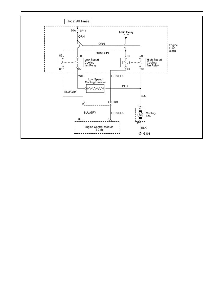
1F – 48 ENGINE CONTROLS
DAEWOO M-150 BL2
MAA1F090
ENGINE COOLING FAN CIRCUIT CHECK
Circuit Description
The engine cooling fan circuit operates the cooling fan.
The cooling fan is controlled by the engine control mod-
ule (ECM) based on input from the coolant temperature
sensor (CTS) and the A/C ON/OFF. The ECM controls
the low speed cooling fan operation by internally ground-
ing the ECM connector terminal 39. This energizes the
low speed cooling fan relay and operates the cooling fan
at low speed. The low speed cooling fan operation is
achieved by the cooling fan resistor causing a drop in
the voltage supplied to the cooling fan. The ECM con-
trols the high speed cooling fan operation by internally
grounding the ECM connector terminal 5. This ener-
gizes the high speed cooling fan relay, bypassing the ra-
diator fan resistor. This results in high speed cooling fan
operation.
Diagnostic Aids
D
If the owner complained of an overheating problem, it
must be determined if the complaint was due to an
actual boil over, or the engine coolant temperature
gauge indicated overheating. If the engine is over-
heating and the cooling fans are on, the cooling sys-
tem should be checked.
D
If the engine fuse block fuse EF15 become open
(blown) immediately after installation, inspect for a
short to ground in the wiring of the appropriate circuit.
If the fuse become open (blown) when the cooling
fans are to be turned on by the Engine Control Mod-
ule (ECM), suspect a faulty cooling fan motor.
D
The ECM will turn the cooling fan on at low speed
when the coolant temperature is 93
_
C (199
_
F). The
ECM will turn the cooling fans off when the coolant
temperature is 90
_
C (194
_
F).
D
The ECM will turn the cooling fans on at high speed
when the coolant temperature is 100
_
C (212
_
F). The
ECM will change the cooling fans from high speed to
low speed when the coolant temperature is 97
_
C
(207
_
F).

ENGINE CONTROLS 1F – 49
DAEWOO M-150 BL2
Engine Cooling Fan Circuit Check
Step
Action
Value(s)
Yes
No
1
Perform an Euro On-Board Diagnostic (EOBD)
System Check.
Was the check performed?
–
Go to Step 2
Go to “Euro
On-Board
Diagnostic
System Check.
2
1. Check the fuses EF3 and EF10 in engine fuse
block.
2. Replace the fuse(s) as needed.
Is the fuse(s) OK?
–
Go to Step 3
Go to
“Diagnostic
Aids”
3
1. Turn the ignition OFF.
2. Turn the A/C switch OFF. If equipped.
3. Connect a scan tool to the Data Link Connector
(DLC).
4. Start the engine.
5. The main cooling fan should run at low speed
when the coolant temperature reaches 96
_
C
(205
_
F).
Does the cooling fan run at low speed?
–
Go to Step 4
Go to Step 8
4
The cooling fans should run at high speed when the
coolant temperature reaches 100
_
C (212
_
F).
Do the cooling fans run at high speed?
–
Go to Step 5
Go to Step 19
5
1. Turn the ignition OFF.
2. Start the engine.
3. Turn the A/C switch ON.
Does the cooling fan runs at low speed?
–
Go to Step 7
Go to Step 6
6
1. Diagnose the A/C compressor clutch circuit.
2. Repair the A/C compressor clutch circuit as
needed.
Is the repair complete?
–
System OK
–
7
1. Turn the ignition OFF.
2. Start the engine.
3. Turn the A/C switch ON and raise the rpm.
4. The cooling fan should run at high speed when
the high side A/C pressure reaches 2068 kPa
(300 psi).
Do the cooling fans run at high speed?
–
System OK
–
8
1. Turn the ignition OFF.
2. Disconnect the cooling fan connector.
3. Turn the ignition ON.
4. Connect a test light between terminal 1 of cooling
fan connector and ground.
Is the test light on?
–
Go to Step 9
Go to Step 12
9
Connect a test light between terminal 2 of cooling
fan connector and battery positive.
Is the test light on?
–
Go to Step 11
Go to Step 10
10
Repair open circuit between terminal 2 of cooling fan
connector and ground.
Is the repair complete?
–
System OK
–
11
Check for a damaged terminals in main cooling fan
connector and repair it or replace the main cooling
fan.
Is the repair complete?
–
System OK
–

1F – 50 ENGINE CONTROLS
DAEWOO M-150 BL2
Engine Cooling Fan Circuit Check (Cont’d)
Step
Action
Value(s)
Yes
No
12
1. Turn the ignition ON.
2. Connect a test light between terminals 86 and 30
of low speed cooling fan relay and ground.
Does the test light on for both case?
–
Go to Step 14
Go to Step 13
13
Repair power supply circuit.
D
Fuse EF15 and terminal 30 of low speed cooling
fan relay.
Is the repair complete?
–
System OK
Go to Step 14
14
1. Turn the ignition OFF.
2. Disconnect Engine Control Module (ECM)
connectors.
3. Turn the ignition ON.
4. Connect a jump wire between terminal 5 and
ground.
Does the cooling fan run at low speed?
–
Go to Step 15
Go to Step 16
15
Replace the ECM.
Is the repair complete?
–
System OK
–
16
1. Turn the ignition OFF.
2. Measure the resistance between following
terminals:
D
Terminal 85 of low speed cooling fan relay and
terminal 39 of ECM connector.
Are the resistance within the value specified?
0
Ω
Go to Step 18
Go to Step 17
17
Repair open circuit.
Is the repair complete?
–
System OK
–
18
Replace the low speed cooling fan relay.
Is the repair complete?
–
System OK
–

ENGINE CONTROLS 1F – 51
DAEWOO M-150 BL2
BLANK
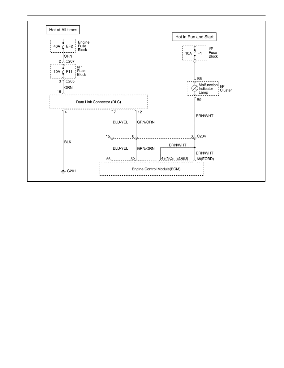
1F – 52 ENGINE CONTROLS
DAEWOO M-150 BL2
MAA1F010
DATA LINK CONNECTOR DIAGNOSIS
Circuit Description
The provision for communicating with the Engine Con-
trol Module (ECM) is the Data Link Connector (DLC). It
is located under the instrument panel. The DLC is used
to connect the scan tool. Battery power and ground is
supplied for the scan tool through the DLC. The Key-
word 2000 serial data circuit to the DLC allows the ECM
to communicate with the scan tool. A Universal Asyn-
chronous Receiver Transmitter (UART) serial data line
is used to communicate with the other modules such as
the Electronic Brake Control Module (EBCM), the Sup-
plemental Inflatable Restraint (SIR) system. and the In-
strument Panel Cluster.
Diagnostic Aids
Ensure that the correct application (model line, car year,
etc.) has been selected on the scan tool. If communica-
tion still cannot be established, try the scan tool on
another vehicle to ensure that the scan tool or cables
are not the cause of the condition.
An intermittent may be caused by a poor connection,
rubbed through wire insulation, or a broken wire inside
the insulation.
Any circuitry that is suspected of causing an intermittent
complaint should be thoroughly checked for the follow-
ing conditions:
D
Backed-out terminals.
D
Improper mating of terminals.
D
Broken locks.
D
Improperly formed or damaged terminals.
D
Poor terminal-to-wiring connection.
D
Physical damage to the wiring harness.
D
Corrosion.

ENGINE CONTROLS 1F – 53
DAEWOO M-150 BL2
Data Link Connector Diagnosis
Step
Action
Value(s)
Yes
No
1
Perform an Euro On-Board Diagnostic (EOBD)
System Check.
Was the check performed?
–
Go to Step 2
Go to “Euro
On-Board
Diagnostic
System Check.
2
With a test light connected to the ground, probe the
Data Link Connector (DLC) battery feed terminal 16.
Is the test light on?
–
Go to Step 4
Go to Step 3
3
Repair an open or short to ground in the DLC battery
feed circuit .
Is the repair complete?
–
Go to Step 4
–
4
With a test light connected to the battery, probe the
Data Link Connector (DLC) ground terminal 4 and 5.
Is the test light on?
–
Go to Step 6
Go to Step 5
5
Repair an open circuit .
Is the repair complete?
–
Go to Step 6
–
6
1. Turn the ignition OFF.
2. Connect a scan tool to the Data Link Connector
(DLC).
3. Turn the ignition ON.
Does the scan tool power up?
–
Go to Step 8
Go to Step 7
7
Check for damages in the terminal of DLC and scan
tool, and repair as needed.
Is the repair complete?
–
Go to Step 8
–
8
Using a scan tool, request engine data of Engine
Control Module (ECM).
Does the scan tool display any data?
–
Go to Step 12
Go to Step 9
9
Install the scan tool on another vehicle and check for
proper operation.
Does the scan tool work properly on a different
vehicle.
–
Go to Step 11
Go to Step 10
10
The scan tool is malfunctioning.
Refer to the scan tool’s manual for repair.
Is the repair complete?
–
Go to Step 12
–
11
Repair communication circuit between ECM and
DLC.
Is the repair complete?
–
Go to Step 12
–
12
1. Using a scan tool, clear the Diagnostic Trouble
Codes(DTCs).
2. Attempt to start the engine.
Does the engine and continue to run?
–
Go to Step 13
Go to Step 1
13
1. Allow the engine to idle until normal operation
temperature reached.
2. Check if any DTCs are set?
Are any DTCs displayed that have not been
diagnosed?
–
Go to applicable
DTC table
System OK

1F – 54 ENGINE CONTROLS
DAEWOO M-150 BL2
FUEL INJECTOR BALANCE TEST
A fuel injector tester is used to energize the injector for a
precise amount of time, thus spraying a measured
amount of fuel into the intake manifold. This causes a
drop in the fuel rail pressure that can be recorded and
used to compare each of the fuel injectors. All of the fuel
injectors should have the same pressure drop.
Fuel Injector Balance Test Example
Cylinder
1
2
3
First Reading
380 kPa
(55 psi)
380 kPa
(55 psi)
380 kPa
(55 psi)
Second Reading
215 kPa
(31 psi)
201 kPa
(29 psi)
230 kPa
(33 psi)
Amount Of Drop
165 kPa
(24 psi)
179 kPa
(26 psi)
151 kPa
(22 psi)
Average Range: 156-176 kPa
(22.5-25.5 psi)
Injector OK
Faulty Injector –
Too Much
Pressure Drop
Faulty Injector –
Too Little
Pressure Drop
Caution: The fuel system is under pressure. To
avoid fuel spillage and the risk of personal injury or
fire, it is necessary to relieve the fuel system pres-
sure before disconnecting the fuel lines.
Caution: Do not pinch or restrict fuel lines. Damage
to the lines could cause a fuel leak, resulting in pos-
sible fire or personal injury.
Notice: In order to prevent flooding of the engine, do not
perform the Injector Balance Test more than once (in-
cluding any retest on faulty fuel injectors) without run-
ning the engine.
Test
Notice: An engine cool down period of 10 minutes is
necessary in order to avoid irregular readings due to hot
soak fuel boiling.
1. Connect the fuel pressure gauge carefully to avoid
any fuel spillage.
2. The fuel pump should run about 2 seconds after the
ignition is turned to the ON position.
3. Insert a clear tube attached to the vent valve of the
fuel pressure gauge into a suitable container.
4. Bleed the air from the fuel pressure gauge and hose
until all of the air is bled from the fuel pressure gauge.
5. The ignition switch must be in the OFF position at
least 10 seconds in order to complete the electronic
control module (ECM) shutdown cycle.
6. Turn the ignition ON in order to get the fuel pressure
to its maximum level.
7. Allow the fuel pressure to stabilize and then record
this initial pressure reading. Wait until there is no
movement of the needle on the fuel pressure gauge.
8. Follow the manufacturer’s instructions for the use of
the adapter harness. Energize the fuel injector test-
er once and note the fuel pressure drop at its lowest
point. Record this second reading. Subtract it from
the first reading to determine the amount of the fuel
pressure drop.
9. Disconnect the fuel injector tester from the fuel in-
jector.
10. After turning the ignition ON, in order to obtain maxi-
mum pressure once again, make a connection at
the next fuel injector. Energize the fuel injector test-
er and record the fuel pressure reading. Repeat this
procedure for all the injectors.
11. Retest any of the fuel injectors that the pressure
drop exceeds the 10 kPa (1.5 psi) specification.
12. Replace any of the fuel injectors that fail the retest.
13. If the pressure drop of all of the fuel injectors is with-
in 10 kPa (1.5 psi), then the fuel injectors are flowing
normally and no replacement should be necessary.
14. Reconnect the fuel injector harness and review the
symptom diagnostic tables.
Wyszukiwarka
Podobne podstrony:
10 Engine Control System
Computer engine control
M31f4 Engine Controls 280 324
ENGINE CONTROL SYSTEM
10 Engine Control System
M31f3 Engine Controls 152 279
Engine Control V6
Engine Control I4
Engine Control I4
Engine Control V6
M31f2 Engine Controls 55 151
10 Engine Control System
Computer engine control
M31f4 Engine Controls 280 324
ENGINE CONTROLS SECTION 1F 14
więcej podobnych podstron