
HA-1
VENTILATION, HEATER & AIR CONDITIONER
C
D
E
F
G
H
J
K
L
M
SECTION
HA
A
B
HA
N
O
P
CONTENTS
HEATER & AIR CONDITIONING SYSTEM
PRECAUTION ...............................................
PRECAUTIONS ...................................................
Precaution for Working with HFC-134a (R-134a) ......
Precaution for Procedure without Cowl Top Cover
......
Contaminated Refrigerant .........................................
General Refrigerant Precaution ................................
Precaution for Leak Detection Dye ...........................
A/C Identification Label .............................................
Precaution for Refrigerant Connection ......................
Precaution for Service of Compressor ......................
Precaution for Service Equipment .............................
PREPARATION ...........................................
PREPARATION ..................................................
Special Service Tool ...............................................
HFC-134a (R-134a) Service Tool and Equipment
Commercial Service Tool ........................................
FUNCTION DIAGNOSIS ..............................
REFRIGERATION SYSTEM ..............................
Refrigerant Cycle ....................................................
Refrigerant System Protection ................................
Component ..............................................................
OIL ......................................................................
Maintenance of Oil Quantity in Compressor ...........
ON-VEHICLE MAINTENANCE ....................
OIL ......................................................................
Maintenance of Oil Quantity in Compressor ...........
REFRIGERATION SYSTEM ..............................
HFC-134a (R-134a) Service Procedure ..................
Checking of Refrigerant Leaks ................................
FLUORESCENT LEAK DETECTOR ................
Dye Injection ............................................................
ELECTRICAL LEAK DETECTOR ....................
Electronic Refrigerant Leak Detector .......................
ON-VEHICLE REPAIR .................................
REFRIGERATION SYSTEM .............................
Component ..............................................................
HFC-134a (R-134a) Service Procedure ..................
COMPRESSOR .................................................
Removal and Installation for Compressor ...............
Removal and Installation for Compressor Clutch ....
LOW-PRESSURE FLEXIBLE HOSE ................
LOW-PRESSURE PIPE ....................................
Removal and Installation for Low-Pressure Pipe .....
HIGH-PRESSURE FLEXIBLE HOSE ...............
HIGH-PRESSURE PIPE ....................................
Removal and Installation for High-pressure Pipe ....
CONDENSER ....................................................
Removal and Installation for Condenser .................
REFRIGERANT PRESSURE SENSOR ............
EXPANSION VALVE .........................................
Removal and Installation for Expansion Valve ........
AMBIENT SENSOR ..........................................
2008 Titan
Revision: October 2007

HA-2
Removal and Installation ........................................
SERVICE DATA AND SPECIFICATIONS
(SDS) ...........................................................
Service Data and Specification (SDS) ....................
2008 Titan
Revision: October 2007

PRECAUTIONS
HA-3
< PRECAUTION >
C
D
E
F
G
H
J
K
L
M
A
B
HA
N
O
P
PRECAUTION
PRECAUTIONS
Precaution for Supplemental Restraint System (SRS) "AIR BAG" and "SEAT BELT
PRE-TENSIONER"
INFOID:0000000001308866
The Supplemental Restraint System such as “AIR BAG” and “SEAT BELT PRE-TENSIONER”, used along
with a front seat belt, helps to reduce the risk or severity of injury to the driver and front passenger for certain
types of collision. This system includes seat belt switch inputs and dual stage front air bag modules. The SRS
system uses the seat belt switches to determine the front air bag deployment, and may only deploy one front
air bag, depending on the severity of a collision and whether the front occupants are belted or unbelted.
Information necessary to service the system safely is included in the SR and SB section of this Service Man-
ual.
WARNING:
• To avoid rendering the SRS inoperative, which could increase the risk of personal injury or death in
the event of a collision which would result in air bag inflation, all maintenance must be performed by
an authorized NISSAN/INFINITI dealer.
• Improper maintenance, including incorrect removal and installation of the SRS, can lead to personal
injury caused by unintentional activation of the system. For removal of Spiral Cable and Air Bag
Module, see the SR section.
• Do not use electrical test equipment on any circuit related to the SRS unless instructed to in this
Service Manual. SRS wiring harnesses can be identified by yellow and/or orange harnesses or har-
ness connectors.
Precaution for Working with HFC-134a (R-134a)
INFOID:0000000001308867
WARNING:
• CFC-12 (R-12) refrigerant and HFC-134a (R-134a) refrigerant are not compatible. If the refrigerants
are mixed compressor failure is likely to occur. Refer to
HA-4, "Contaminated Refrigerant"
. To deter-
mine the purity of HFC-134a (R-134a) in the vehicle and recovery tank, use the recovery/recycling
equipment and refrigerant identifier.
• Use only specified oil for the HFC-134a (R-134a) A/C system and HFC-134a (R-134a) components. If
oil other than that specified is used, compressor failure is likely to occur.
• The specified HFC-134a (R-134a) oil rapidly absorbs moisture from the atmosphere. The following
handling precautions must be observed:
- When removing refrigerant components from a vehicle, immediately cap (seal) the component to
minimize the entry of moisture from the atmosphere.
- When installing refrigerant components to a vehicle, do not remove the caps (unseal) until just
before connecting the components. Connect all refrigerant loop components as quickly as possible
to minimize the entry of moisture into system.
- Only use the specified oil from a sealed container. Immediately reseal containers of oil. Without
proper sealing, oil will become moisture saturated and should not be used.
- Avoid breathing A/C refrigerant and oil vapor or mist. Exposure may irritate eyes, nose and throat.
Remove HFC-134a (R-134a) from the A/C system using certified service equipment meeting require-
ments of SAE J2210 [HFC-134a (R-134a) recycling equipment], or J2209 [HFC-134a (R-134a) recovery
equipment]. If accidental system discharge occurs, ventilate work area before resuming service.
Additional health and safety information may be obtained from refrigerant and oil manufacturers.
- Do not allow A/C oil to come in contact with styrofoam parts. Damage may result.
2008 Titan
Revision: October 2007
HA-4
< PRECAUTION >
PRECAUTIONS
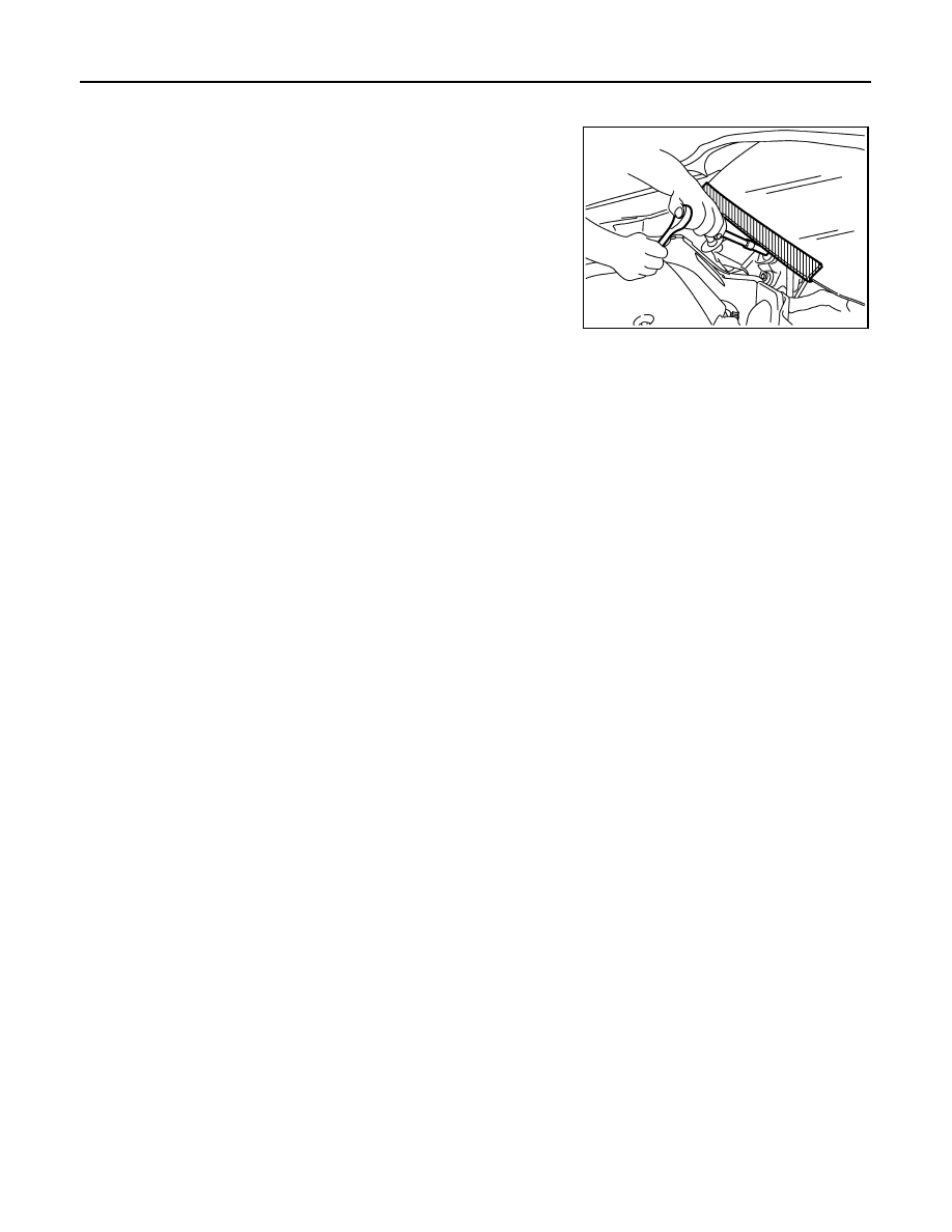
Precaution for Procedure without Cowl Top Cover
INFOID:0000000001308932
When performing the procedure after removing cowl top cover, cover
the lower end of windshield with urethane, etc.
Contaminated Refrigerant
INFOID:0000000001308868
If a refrigerant other than pure HFC-134a (R-134a) is identified in a vehicle, your options are:
• Explain to the customer that environmental regulations prohibit the release of contaminated refrigerant into
the atmosphere.
• Explain that recovery of the contaminated refrigerant could damage your service equipment and refrigerant
supply.
• Suggest the customer return the vehicle to the location of previous service where the contamination may
have occurred.
• If you choose to perform the repair, recover the refrigerant using only dedicated equipment and contain-
ers. Do not recover contaminated refrigerant into your existing service equipment. If your facility does
not have dedicated recovery equipment, you may contact a local refrigerant product retailer for available ser-
vice. This refrigerant must be disposed of in accordance with all federal and local regulations. In addition,
replacement of all refrigerant system components on the vehicle is recommended.
• If the vehicle is within the warranty period, the air conditioner warranty is void. Please contact NISSAN Cus-
tomer Affairs for further assistance.
General Refrigerant Precaution
INFOID:0000000001308869
WARNING:
• Do not release refrigerant into the air. Use approved recovery/recycling equipment to capture the
refrigerant every time an air conditioning system is discharged.
• Always wear eye and hand protection (goggles and gloves) when working with any refrigerant or air
conditioning system.
• Do not store or heat refrigerant containers above 52
°
C (125
°
F).
• Do not heat a refrigerant container with an open flame; if container warming is required, place the
bottom of the container in a warm pail of water.
• Do not intentionally drop, puncture, or incinerate refrigerant containers.
• Keep refrigerant away from open flames: poisonous gas will be produced if refrigerant burns.
• Refrigerant will displace oxygen, therefore be certain to work in well ventilated areas to prevent suf-
focation.
• Do not pressure test or leak test HFC-134a (R-134a) service equipment and/or vehicle air condition-
ing systems with compressed air during repair. Some mixtures of air and HFC-134a (R-134a) have
been shown to be combustible at elevated pressures. These mixtures, if ignited, may cause injury or
property damage. Additional health and safety information may be obtained from refrigerant manu-
facturers.
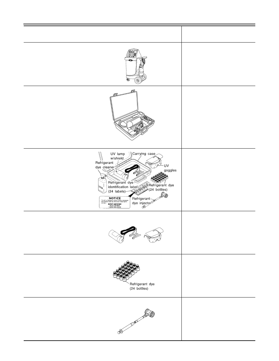
Precaution for Leak Detection Dye
INFOID:0000000001308870
• The A/C system contains a fluorescent leak detection dye used for locating refrigerant leaks. An ultraviolet
(UV) lamp is required to illuminate the dye when inspecting for leaks.
• Always wear fluorescence enhancing UV safety goggles to protect your eyes and enhance the visibility of
the fluorescent dye.
• The fluorescent dye leak detector is not a replacement for an electronic refrigerant leak detector. The fluo-
rescent dye leak detector should be used in conjunction with an electronic refrigerant leak detector (J-
41995).
PIIB3706J
2008 Titan
Revision: October 2007
PRECAUTIONS
HA-5
< PRECAUTION >
C
D
E
F
G
H
J
K
L
M
A
B
HA
N
O
P
• For your safety and the customer's satisfaction, read and follow all manufacturer's operating instructions and
precautions prior to performing work.
• A compressor shaft seal should not be repaired because of dye seepage. The compressor shaft seal should
only be repaired after confirming the leak with an electronic refrigerant leak detector (J-41995).
• Always remove any dye from the leak area after repairs are complete to avoid a misdiagnosis during a future
service.
• Do not allow dye to come into contact with painted body panels or interior components. If dye is spilled,
clean immediately with the approved dye cleaner. Fluorescent dye left on a surface for an extended period of
time cannot be removed.
• Do not spray the fluorescent dye cleaning agent on hot surfaces (engine exhaust manifold, etc.).
• Do not use more than one refrigerant dye bottle (1/4 ounce / 7.4 cc) per A/C system.
• Leak detection dyes for HFC-134a (R-134a) and CFC-12 (R-12) A/C systems are different. Do not use HFC-
134a (R-134a) leak detection dye in CFC-12 (R-12) A/C systems or CFC-12 (R-12) leak detection dye in
HFC-134a (R-134a) A/C systems or A/C system damage may result.
• The fluorescent properties of the dye will remain for over three (3) years unless a compressor failure occurs.
A/C Identification Label
INFOID:0000000001308871
Vehicles with factory installed fluorescent dye have this identification label on the underside of hood.
Precaution for Refrigerant Connection
INFOID:0000000001308872
A new type refrigerant connection has been introduced to all refrigerant lines except the following locations.
• Expansion valve to cooling unit
• Evaporator pipes to evaporator (inside cooling unit)
• Refrigerant pressure sensor
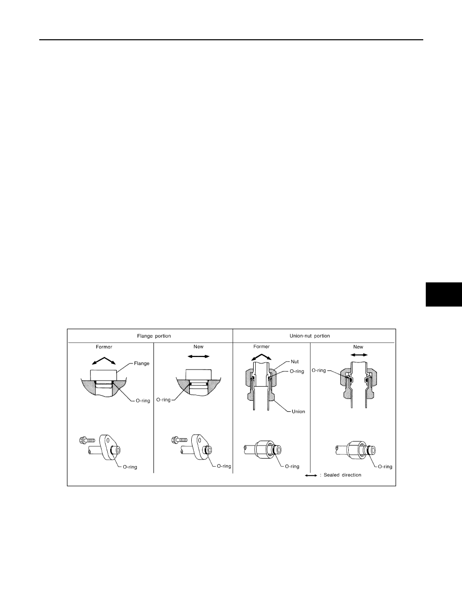
FEATURES OF NEW TYPE REFRIGERANT CONNECTION
• The O-ring has been relocated. It has also been provided with a groove for proper installation. This reduces
the possibility of the O-ring being caught in, or damaged by, the mating part. The sealing direction of the O-
ring is now set vertically in relation to the contacting surface of the mating part to improve sealing character-
istics.
• The reaction force of the O-ring will not occur in the direction that causes the joint to pull out, thereby facili-
tating piping connections.
O-RING AND REFRIGERANT CONNECTION
SHA815E
2008 Titan
Revision: October 2007
HA-6
< PRECAUTION >
PRECAUTIONS
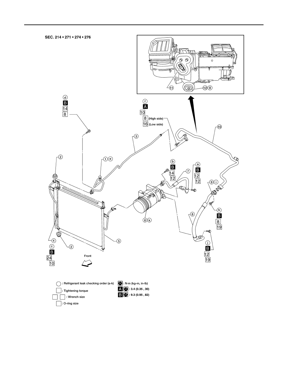
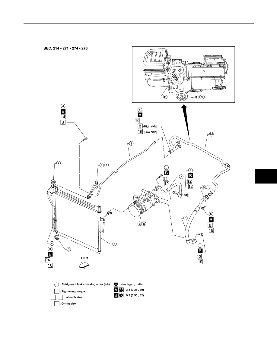
A/C Compressor and Condenser
CAUTION:
WJIA1577E
1.
High-pressure service valve
2.
Grommet
3.
High-pressure pipe
4.
Refrigerant pressure sensor
5.
Condenser
6.
Compressor shaft seal
7.
High-pressure flexible hose
8.
Low-pressure flexible hose
9.
Low-pressure service valve
10. Low-pressure pipe
11.
Expansion valve
12. Drain hose
2008 Titan
Revision: October 2007
PRECAUTIONS
HA-7
< PRECAUTION >
C
D
E
F
G
H
J
K
L
M
A
B
HA
N
O
P
The new and former refrigerant connections use different O-ring configurations. Do not confuse O-
rings since they are not interchangeable. If a wrong O-ring is installed, refrigerant will leak at or
around the connection.
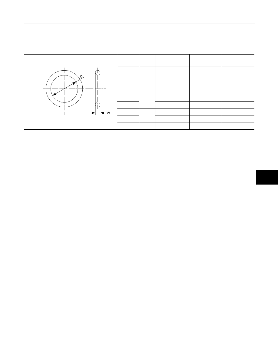
O-Ring Part Numbers and Specifications
*: Always check with the Parts Department for the latest parts information.
WARNING:
Make sure all refrigerant is discharged into the recycling equipment and the pressure in the system is
less than atmospheric pressure. Then gradually loosen the discharge side hose fitting and remove it.
CAUTION:
When replacing or cleaning refrigerant cycle components, observe the following.
• When the compressor is removed, store it in the same position as it is when mounted on the car.
Failure to do so will cause oil to enter the low pressure chamber.
• When connecting tubes, always use a torque wrench and a back-up wrench.
• After disconnecting tubes, immediately plug all openings to prevent entry of dirt and moisture.
• When installing an air conditioner in the vehicle, connect the pipes as the final stage of the opera-
tion. Do not remove the seal caps of pipes and other components until just before required for con-
nection.
• Allow components stored in cool areas to warm to working area temperature before removing seal
caps. This prevents condensation from forming inside A/C components.
• Thoroughly remove moisture from the refrigeration system before charging the refrigerant.
• Always replace used O-rings.
• When connecting tube, apply oil to circle of the O-rings shown in illustration. Be careful not to apply
oil to threaded portion.
Oil name: NISSAN A/C System Oil Type S or equivalent
• O-ring must be closely attached to dented portion of tube.
• When replacing the O-ring, be careful not to damage O-ring and tube.
• Connect tube until you hear it click, then tighten the nut or bolt by hand until snug. Make sure that
the O-ring is installed to tube correctly.
• After connecting line, conduct leak test and make sure that there is no leakage from connections.
When the gas leaking point is found, disconnect that line and replace the O-ring. Then tighten con-
nections of seal seat to the specified torque.
Connec-
tion type
O-ring
size
Part number*
D
mm (in)
W
mm (in)
New
8
92471 N8210
6.8 (0.268)
1.85 (0.0728)
Former
10
J2476 89956
9.25 (0.3642)
1.78 (0.0701)
New
12
92472 N8210
10.9 (0.429)
2.43 (0.0957)
Former
92475 71L00
11.0 (0.433)
2.4 (0.094)
New
16
92473 N8210
13.6 (0.535)
2.43 (0.0957)
Former
92475 72L00
14.3 (0.563)
2.3 (0.091)
New
19
92474 N8210
16.5 (0.650)
2.43 (0.0957)
Former
92477 N8200
17.12 (0.6740)
1.78 (0.0701)
New
24
92195 AH300
21.8 (0.858)
2.4 (0.094)
SHA814E
2008 Titan
Revision: October 2007
HA-8
< PRECAUTION >
PRECAUTIONS
Precaution for Service of Compressor
INFOID:0000000001308873
• Plug all openings to prevent moisture and foreign matter from entering.
• When the compressor is removed, store it in the same position as it is when mounted on the car.
• When replacing or repairing compressor, follow “Maintenance of Oil Quantity in Compressor”
exactly. Refer to
HA-20, "Maintenance of Oil Quantity in Compressor"
.
• Keep friction surfaces between clutch and pulley clean. If the surface is contaminated with oil, wipe
it off by using a clean waste cloth moistened with thinner.
• After compressor service operation, turn the compressor shaft by hand more than 5 turns in both
directions. This will equally distribute oil inside the compressor. After the compressor is installed,
let the engine idle and operate the compressor for 1 hour.
• After replacing the compressor magnet clutch, apply voltage to the new one and check for normal
operation. Refer to
HA-34, "Removal and Installation for Compressor Clutch"
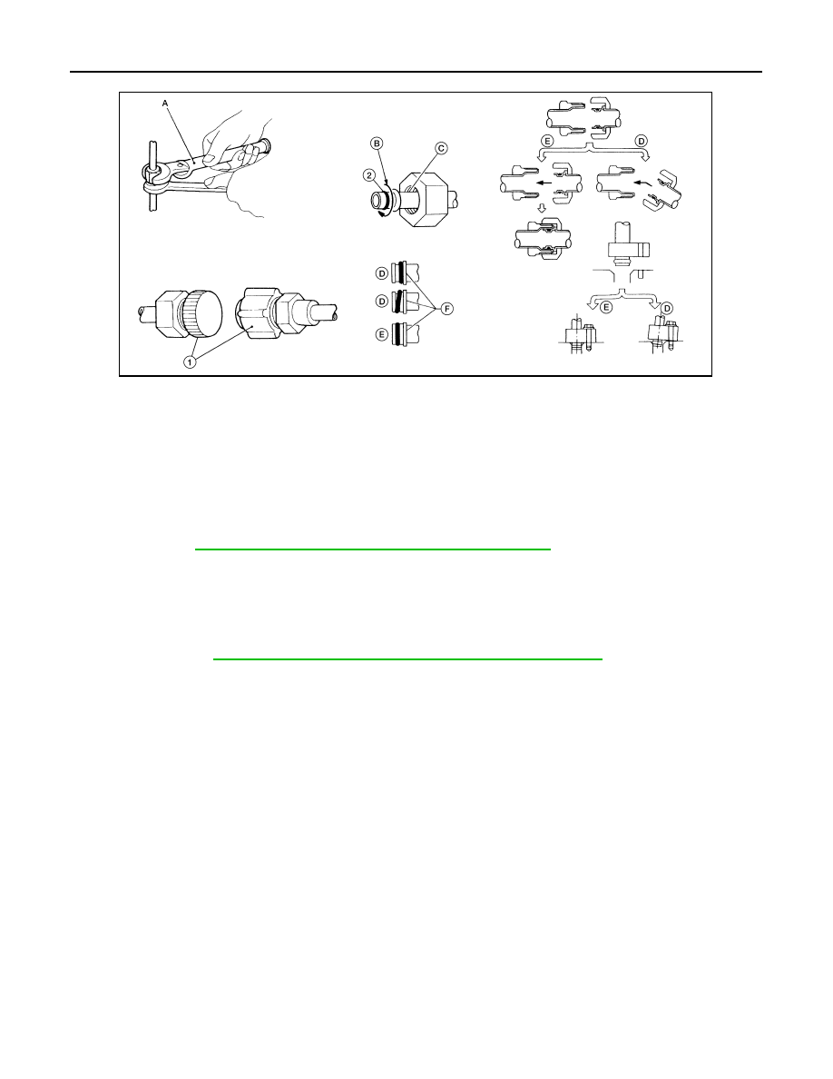
Precaution for Service Equipment
INFOID:0000000001308874
RECOVERY/RECYCLING EQUIPMENT
Follow the manufacturer's instructions for machine operation and machine maintenance. Never introduce any
refrigerant other than that specified into the machine.
ELECTRONIC LEAK DETECTOR
Follow the manufacturer's instructions for tester operation and tester maintenance.
VACUUM PUMP
1.
Plug
2.
O-ring
A.
Torque wrench
B.
Apply oil
C.
Do not apply oil to threads
D.
NG (no good)
E.
OK (okay)
F.
Inflated portion
WJIA1774E
2008 Titan
Revision: October 2007
PRECAUTIONS
HA-9
< PRECAUTION >
C
D
E
F
G
H
J
K
L
M
A
B
HA
N
O
P
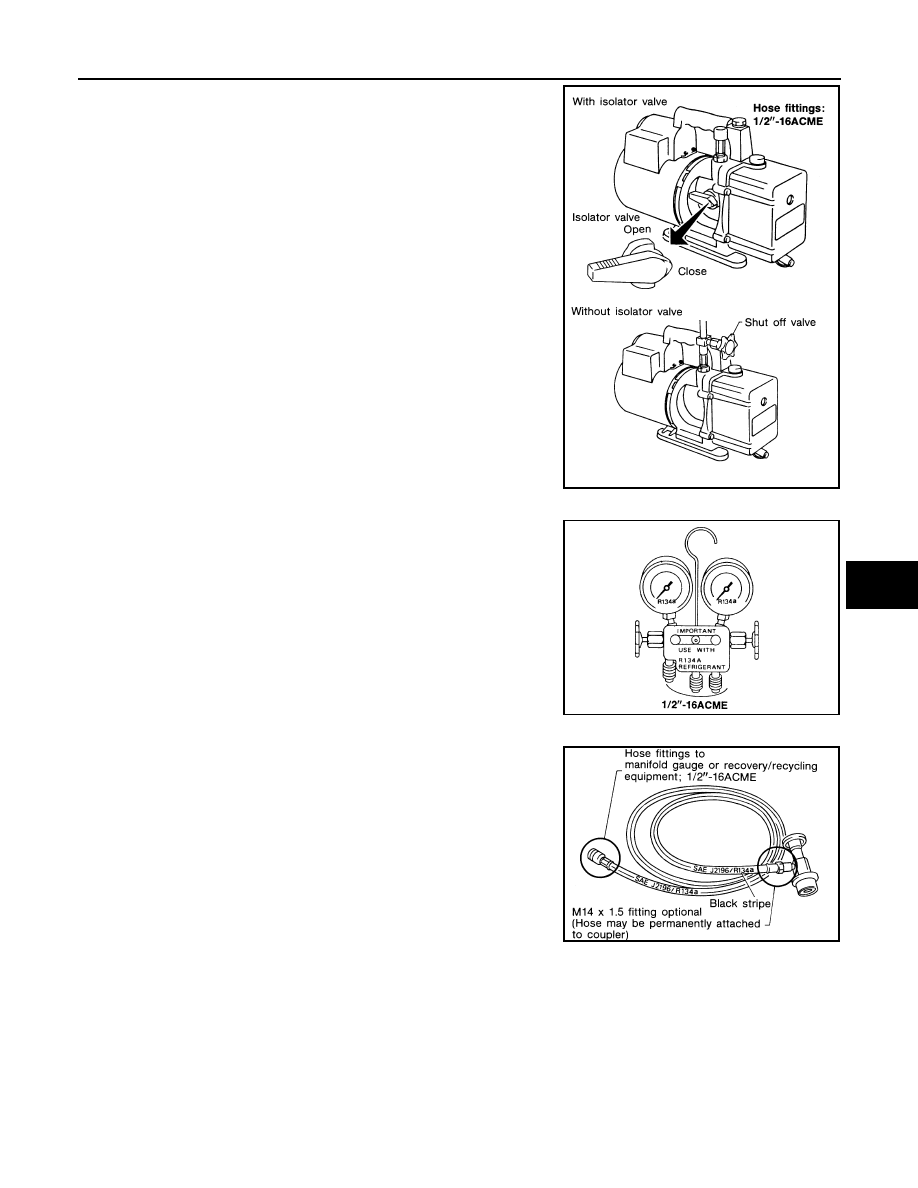
The oil contained inside the vacuum pump is not compatible with the
specified oil for HFC-134a (R-134a) A/C systems. The vent side of
the vacuum pump is exposed to atmospheric pressure so the vac-
uum pump oil may migrate out of the pump into the service hose.
This is possible when the pump is switched off after evacuation (vac-
uuming) and hose is connected to it.
To prevent this migration, use a manual valve situated near the
hose-to-pump connection, as follows.
• Usually vacuum pumps have a manual isolator valve as part of the
pump. Close this valve to isolate the service hose from the pump.
• For pumps without an isolator, use a hose equipped with a manual
shut-off valve near the pump end. Close the valve to isolate the
hose from the pump.
• If the hose has an automatic shut off valve, disconnect the hose
from the pump: as long as the hose is connected, the valve is open
and lubricating oil may migrate.
Some one-way valves open when vacuum is applied and close
under a no vacuum condition. Such valves may restrict the pump's
ability to pull a deep vacuum and are not recommended.
MANIFOLD GAUGE SET
Be certain that the gauge face indicates HFC-134a (R-134a or
134a). Make sure the gauge set has 1/2
″
-16 ACME threaded con-
nections for service hoses. Confirm the set has been used only with
refrigerant HFC-134a (R-134a) along with specified oil.
SERVICE HOSES
Be certain that the service hoses display the markings described
(colored hose with black stripe). All hoses must include positive shut-
off devices (either manual or automatic) near the end of the hoses
opposite the manifold gauge.
SERVICE COUPLERS
RHA270D
SHA533D
RHA272D
2008 Titan
Revision: October 2007
HA-10
< PRECAUTION >
PRECAUTIONS
Never attempt to connect HFC-134a (R-134a) service couplers to a
CFC-12 (R-12) A/C system. The HFC-134a (R-134a) couplers will
not properly connect to the CFC-12 (R-12) system. If an improper
connection is attempted, discharging and contamination may occur.
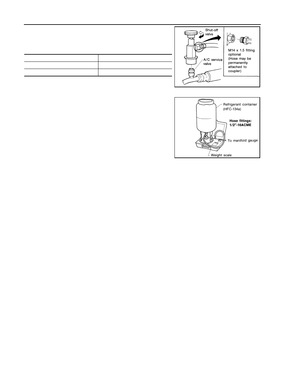
REFRIGERANT WEIGHT SCALE
Verify that no refrigerant other than HFC134a (R-134a) and specified
oils have been used with the scale. If the scale controls refrigerant
flow electronically, the hose fitting must be 1/2”-16 ACME.
CHARGING CYLINDER
Using a charging cylinder is not recommended. Refrigerant may be vented into air from cylinder's top valve
when filling the cylinder with refrigerant. Also, the accuracy of the cylinder is generally less than that of an
electronic scale or of quality recycle/recharge equipment.
Shut-off valve rotation
A/C service valve
Clockwise
Open
Counterclockwise
Close
RHA273D
RHA274D
2008 Titan
Revision: October 2007
PREPARATION
HA-11
< PREPARATION >
C
D
E
F
G
H
J
K
L
M
A
B
HA
N
O
P
PREPARATION
PREPARATION
Special Service Tool
INFOID:0000000001308875
The actual shapes of Kent-Moore tools may differ from those of special service tools illustrated here.
HFC-134a (R-134a) Service Tool and Equipment
INFOID:0000000001308876
Never mix HFC-134a (R-134a) refrigerant and/or the specified oil with CFC-12 (R-12) refrigerant and/or the
oil.
Separate and non-interchangeable service equipment must be used for handling each type of refrigerant/oil.
Refrigerant container fittings, service hose fittings and service equipment fittings (equipment which handles
refrigerant and/or oil) are different between CFC-12 (R-12) and HFC-134a (R-134a). This is to avoid mixed
use of the refrigerants/oil.
Adapters that convert one size fitting to another must never be used refrigerant/oil contamination will occur
and compressor failure will result.
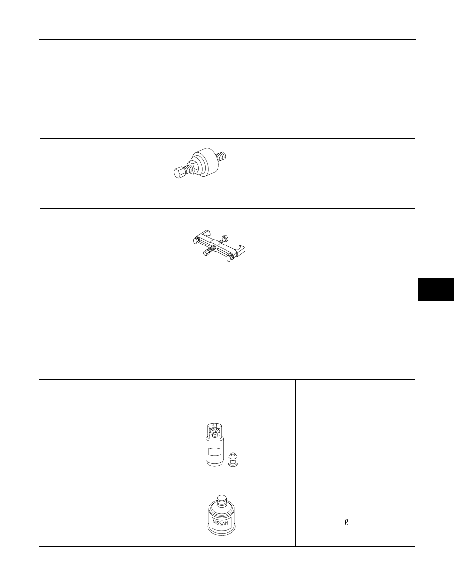
Tool number
(Kent-Moore No.)
Tool name
Description
—
(J-38873-A)
Pulley installer
Installing pulley
KV99233130
(J-29884)
Pulley puller
Removing pulley
LHA171
LHA172
Tool number
(Kent-Moore No.)
Tool name
Description
HFC-134a (R-134a)
(
—
)
Refrigerant
Container color: Light blue
Container marking: HFC-134a (R-
134a)
Fitting size: Thread size
• large container 1/2”-16 ACME
—
(
—
)
NISSAN A/C System Oil Type S
Type: Poly alkylene glycol oil (PAG),
type S
Application: HFC-134a (R-134a)
swash plate compressors (NISSAN
only)
Lubricity: 40 m
(1.4 US fl oz, 1.4 Imp
fl oz)
S-NT196
S-NT197
2008 Titan
Revision: October 2007
HA-12
< PREPARATION >
PREPARATION
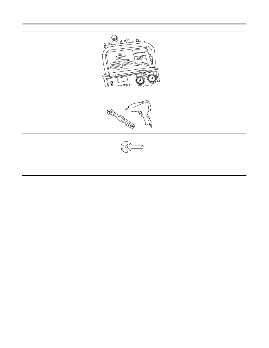
KV991J0130
(ACR2005-NI)
ACR5 A/C Service Center
Refrigerant recovery, recycling and re-
charging
—
(J-41995)
Electronic refrigerant leak detector
Power supply:
• DC 12V (battery terminal)
—
(J-43926)
Refrigerant dye leak detection kit
Kit includes:
(J-42220) UV lamp and UV safety
goggles
(J-41459) Refrigerant dye injector
(J-41447) qty. 24
HFC-134a (R-134a) refrigerant
dye
(J-43872) Refrigerant dye cleaner
Power supply:
• DC 12V (battery terminal)
—
(J-42220)
Fluorescent dye leak detector
Power supply:
• DC 12V (battery terminal)
For checking refrigerant leak when flu-
orescent dye is installed in A/C system.
Includes: UV lamp and UV safety gog-
gles
—
(J-41447)
HFC-134a (R-134a) Fluorescent
leak detection dye
(Box of 24, 1/4 ounce bottles)
Application: For HFC-134a (R-134a)
PAG oil
Container: 1/4 ounce (7.4cc) bottle
(Includes self-adhesive dye identifica-
tion labels for affixing to vehicle after
charging system with dye.)
—
(J-41459)
HFC-134a (R-134a) Dye injector
Use with J-41447, 1/4 ounce bottle
For injecting 1/4 ounce of fluorescent
leak detection dye into A/C system.
Tool number
(Kent-Moore No.)
Tool name
Description
WJIA0293E
AHA281A
ZHA200H
SHA438F
SHA439F
SHA440F
2008 Titan
Revision: October 2007
PREPARATION
HA-13
< PREPARATION >
C
D
E
F
G
H
J
K
L
M
A
B
HA
N
O
P
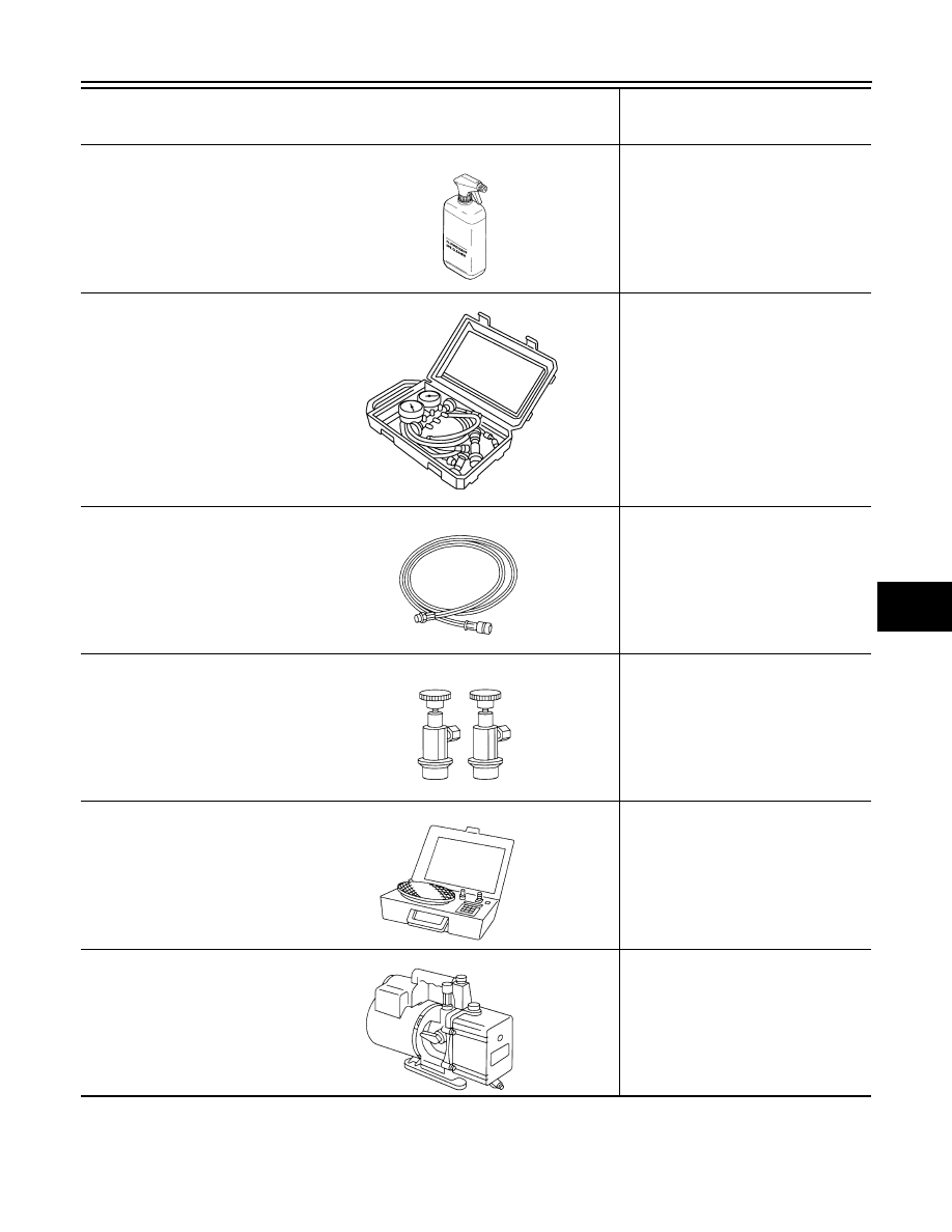
Commercial Service Tool
INFOID:0000000001308877
—
(J-43872)
Refrigerant dye cleaner
For cleaning dye spills.
—
(J-39183-C)
Manifold gauge set (with hoses
and couplers)
Identification:
• The gauge face indicates R-134a.
Fitting size-Thread size
• 1/2”-16 ACME
Service hoses:
• High side hose
(J-39500-72B)
• Low side hose
(J-39500-72R)
• Utility hose
(J-39500-72Y)
Hose color:
• Low side hose: Blue with black stripe
• High side hose: Red with black stripe
• Utility hose: Yellow with black stripe
or green with black stripe
Hose fitting to gauge:
• 1/2”-16 ACME
Service couplers
• High side coupler
(J-39500-20A)
• Low side coupler
(J-39500-24A)
Hose fitting to service hose:
• M14 x 1.5 fitting is optional or perma-
nently attached.
—
(J-39699)
Refrigerant weight scale
For measuring of refrigerant
Fitting size-Thread size
• 1/2”-16 ACME
—
(J-39649)
Vacuum pump
(Including the isolator valve)
Capacity:
• Air displacement: 4 CFM
• Micron rating: 20 microns
• Oil capacity: 482 g (17 oz)
Fitting size-Thread size
• 1/2”-16 ACME
Tool number
(Kent-Moore No.)
Tool name
Description
SHA441F
RJIA0196E
S-NT201
S-NT202
S-NT200
S-NT203
2008 Titan
Revision: October 2007
HA-14
< PREPARATION >
PREPARATION
Tool name
Description
(J-41810-NI)
Refrigerant identifier equipment (R-
134a)
For checking refrigerant purity and
system contamination
Power tool
Loosening bolts and nuts
(J-44614)
Clutch disc holding tool
Clutch disc holding tool
RJIA0197E
PBIC0190E
WHA230
2008 Titan
Revision: October 2007

REFRIGERATION SYSTEM
HA-15
< FUNCTION DIAGNOSIS >
C
D
E
F
G
H
J
K
L
M
A
B
HA
N
O
P
FUNCTION DIAGNOSIS
REFRIGERATION SYSTEM
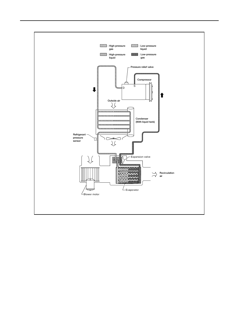
Refrigerant Cycle
INFOID:0000000001308884
REFRIGERANT FLOW
The refrigerant flows in the standard pattern, that is, through the compressor, the condenser with liquid tank,
through the evaporator, and back to the compressor. The refrigerant evaporation through the evaporator coils
are controlled by externally equalized expansion valve, located inside the evaporator case.
Refrigerant System Protection
INFOID:0000000001308885
REFRIGERANT PRESSURE SENSOR
The refrigerant system is protected against excessively high or low pressures by the refrigerant pressure sen-
sor, located on the condenser. If the system pressure rises above or falls below the specifications, the refriger-
ant pressure sensor detects the pressure inside the refrigerant line and sends a voltage signal to the ECM.
The ECM de-energizes the A/C relay to disengage the magnetic compressor clutch when pressure on the high
pressure side detected by refrigerant pressure sensor is over about 2,746 kPa (28 kg/cm
2
, 398 psi), or below
about 120 kPa (1.22 kg/cm
2
, 17.4 psi).
PRESSURE RELIEF VALVE
The refrigerant system is also protected by a pressure relief valve, located in the rear head of the compressor.
When the pressure of refrigerant in the system increases to an abnormal level [more than 2,990 kPa (30.5 kg/
2008 Titan
Revision: October 2007
HA-16
< FUNCTION DIAGNOSIS >
REFRIGERATION SYSTEM
cm
2
, 433.6 psi)], the release port on the pressure relief valve automatically opens and releases refrigerant into
the atmosphere.
WJIA1347E
2008 Titan
Revision: October 2007
REFRIGERATION SYSTEM
HA-17
< FUNCTION DIAGNOSIS >
C
D
E
F
G
H
J
K
L
M
A
B
HA
N
O
P
Component
INFOID:0000000001308886
A/C Compressor and Condenser
WJIA1577E
1.
High-pressure service valve
2.
Grommet
3.
High-pressure pipe
4.
Refrigerant pressure sensor
5.
Condenser
6.
Compressor shaft seal
7.
High-pressure flexible hose
8.
Low-pressure flexible hose
9.
Low-pressure service valve
10. Low-pressure pipe
11.
Expansion valve
12. Drain hose
2008 Titan
Revision: October 2007

HA-18
< FUNCTION DIAGNOSIS >
REFRIGERATION SYSTEM
NOTE:
Refer to
HA-5, "Precaution for Refrigerant Connection"
2008 Titan
Revision: October 2007

OIL
HA-19
< FUNCTION DIAGNOSIS >
C
D
E
F
G
H
J
K
L
M
A
B
HA
N
O
P
OIL
Maintenance of Oil Quantity in Compressor
INFOID:0000000001308887
The oil in the compressor circulates through the system with the refrigerant. Add oil to compressor when
replacing any component or after a large refrigerant leakage has occurred. It is important to maintain the spec-
ified amount.
If oil quantity is not maintained properly, the following malfunctions may result:
• Lack of oil: May lead to a seized compressor
• Excessive oil: Inadequate cooling (thermal exchange interference)
2008 Titan
Revision: October 2007

HA-20
< ON-VEHICLE MAINTENANCE >
OIL
ON-VEHICLE MAINTENANCE
OIL
Maintenance of Oil Quantity in Compressor
INFOID:0000000001308914
CHECKING AND ADJUSTING
CAUTION:
If excessive oil leakage is noted, do not perform the oil return operation.
Start the engine and set the following conditions:
Test Condition
• Engine speed: Idling to 1,200 rpm
• A/C switch: On
• Blower fan speed: MAX position
• Temp. control: Optional [Set so that intake air temperature is 25
°
to 30
°
C (77
°
to 86
°
F)]
• Intake position: Recirculation (
)
• Perform oil return operation for about ten minutes
Adjust the oil quantity according to the following table.
Oil Adjusting Procedure for Components Replacement Except Compressor
After replacing any of the following major components, add the correct amount of oil to the system.
Amount of Oil to be Added
• *1:
If refrigerant leak is small, no addition of oil is needed.
Oil Adjustment Procedure for Compressor Replacement
Part replaced
Oil to be added to system
Remarks
Amount of oil
m
(US fl oz, Imp fl oz)
Evaporator
75 (2.5, 2.6)
—
Condenser
75 (2.5, 2.6)
—
Liquid tank
5 (0.2, 0.2)
Add if compressor is not replaced.
In case of refrigerant leak
30 (1.0, 1.1)
Large leak
—
Small leak *1
2008 Titan
Revision: October 2007
OIL
HA-21
< ON-VEHICLE MAINTENANCE >
C
D
E
F
G
H
J
K
L
M
A
B
HA
N
O
P
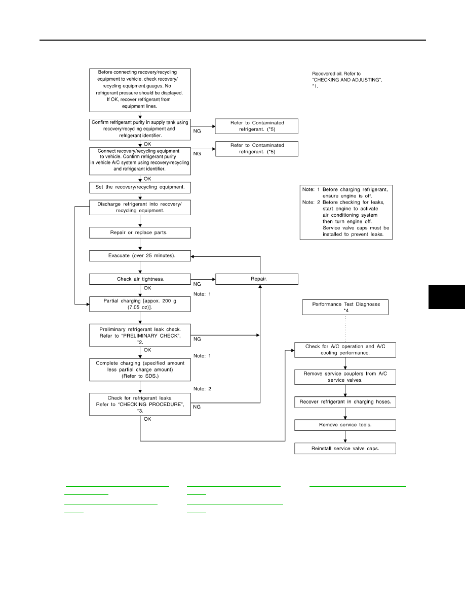
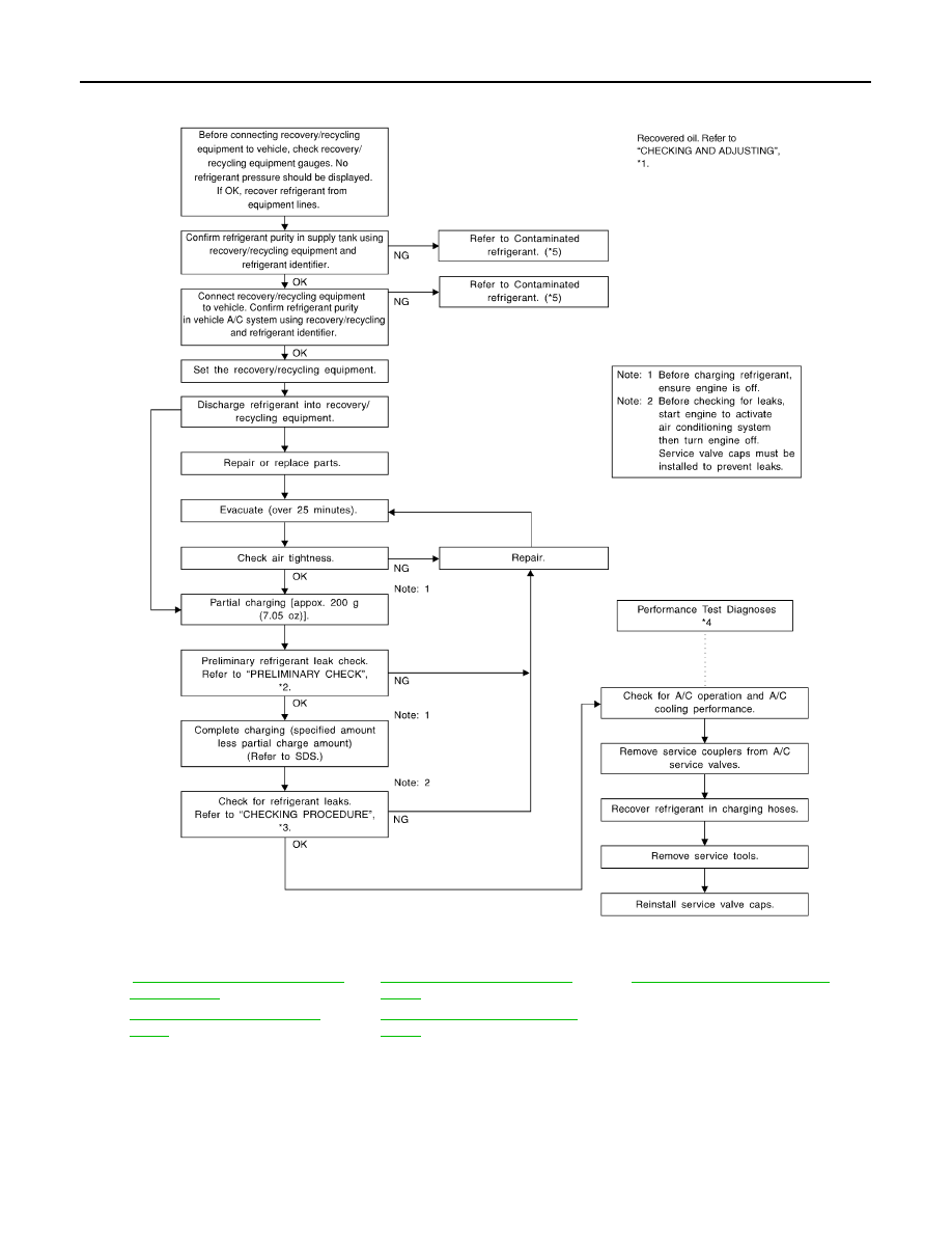
1.
Before connecting recovery/recycling equipment to vehicle, check recovery/recycling equipment gauges.
No refrigerant pressure should be displayed. If NG, recover refrigerant from equipment lines.
2.
Connect recovery/recycling equipment to vehicle. Confirm refrigerant purity in supply tank using recovery/
recycling equipment and refrigerant identifier. If NG, refer to
HA-4, "Contaminated Refrigerant"
3.
Confirm refrigerant purity in vehicle A/C system using recovery/recycling equipment and refrigerant identi-
fier. If NG, refer to
HA-4, "Contaminated Refrigerant"
4.
Discharge refrigerant into the refrigerant recovery/recycling equipment. Measure oil discharged into the
recovery/recycling equipment.
5.
Drain the oil from the “old” (removed) compressor into a graduated container and recover the amount of
oil drained.
6.
Drain the oil from the “new” compressor into a separate, clean container.
7.
Measure an amount of new oil installed equal to amount drained from “old” compressor. Add this oil to
“new” compressor through the suction port opening.
8.
Measure an amount of new oil equal to the amount recovered during discharging. Add this oil to “new”
compressor through the suction port opening.
9.
If the liquid tank also needs to be replaced, add an additional 5 m (0.2 US fl oz, 0.2 Imp fl oz) of oil at this
time.
CAUTION:
Do not add this 5 m (0.2 US fl oz, 0.2 Imp fl oz) of oil if only replacing the compressor.
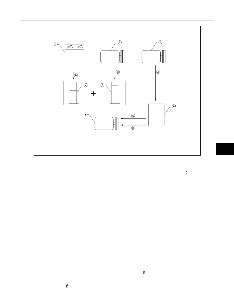
1.
New compressor
2.
Old compressor
3.
Recovery/recycling equipment
4.
Measuring cup X
5.
Measuring cup Y
6.
New oil
A.
Drain oil from the new compressor
into clean container
B.
Record amount of oil recovered
C.
Add an additional 5 m
(0.2 US fl oz,
0.2 Imp fl oz) of new oil when replacing
liquid tank
D.
Install new oil equal to recorded
amounts in measuring cups X plus Y
WJIA1716E
2008 Titan
Revision: October 2007
HA-22
< ON-VEHICLE MAINTENANCE >
REFRIGERATION SYSTEM
REFRIGERATION SYSTEM
HFC-134a (R-134a) Service Procedure
INFOID:0000000001308915
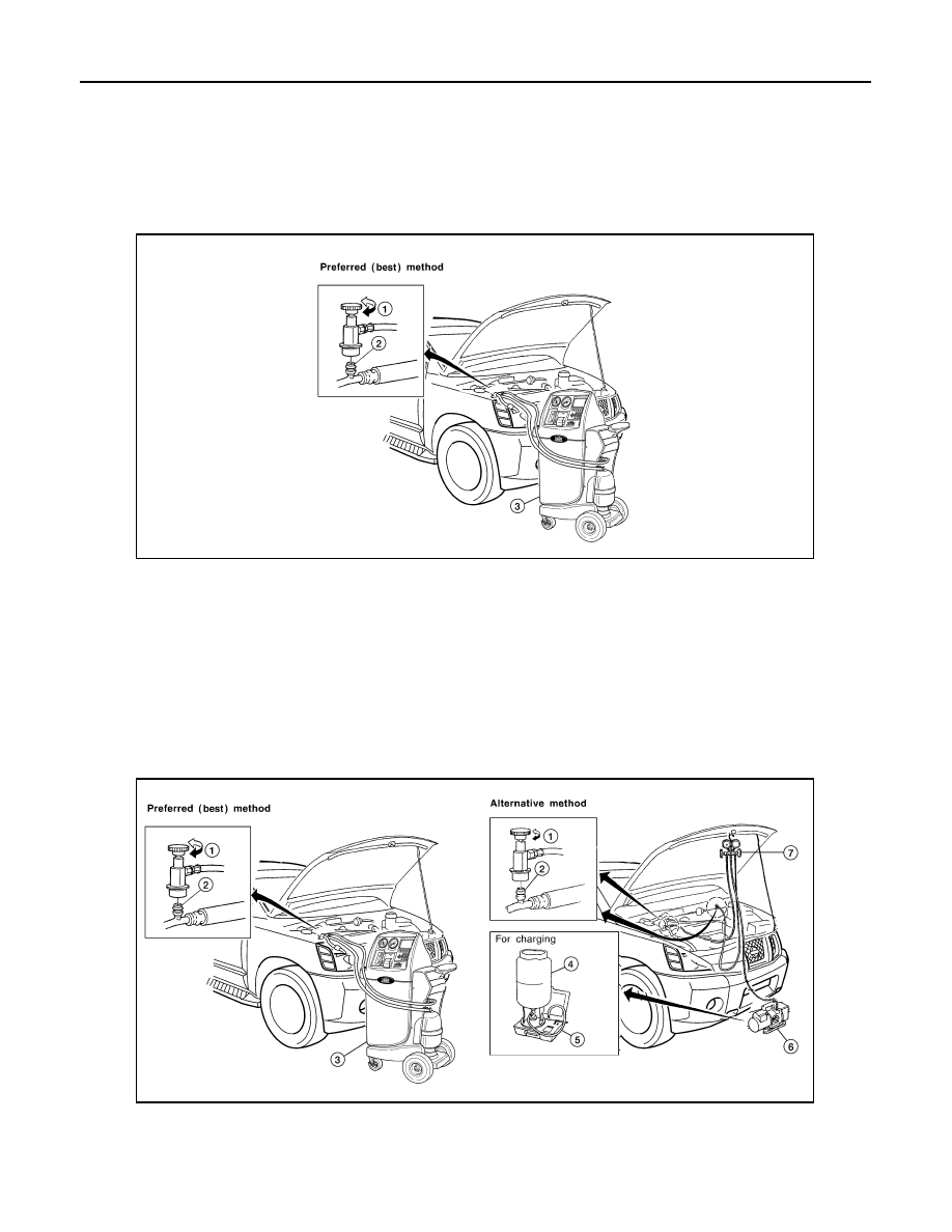
SETTING OF SERVICE TOOLS AND EQUIPMENT
Discharging Refrigerant
WARNING:
Avoid breathing A/C refrigerant and oil vapor or mist. Exposure may irritate eyes, nose and throat.
Remove HFC-134a (R-134a) refrigerant from the A/C system using certified service equipment meeting
requirements of SAE J2210 HFC-134a (R-134a) recycling equipment or SAE J2201 HFC-134a (R-134a)
recovery equipment. If an accidental system discharge occurs, ventilate the work area before resum-
ing service. Additional health and safety information may be obtained from the refrigerant and oil man-
ufacturers.
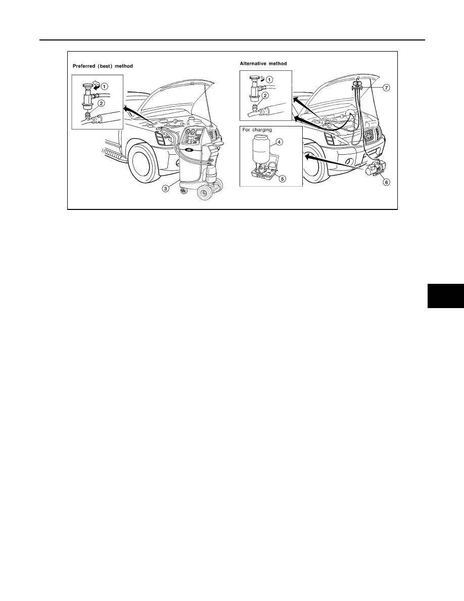
Evacuating System and Charging Refrigerant
1.
Shut-off valve
2.
A/C service valve
3.
Recovery/recycling equipment
WJIA0579E
1.
Shut-off valve
2.
A/C service valve
3.
Recovery/recycling equipment
4.
Refrigerant container (HFC-134a)
5.
Weight scale (J-39650)
6.
Evacuating vacuum pump (J-39699)
7.
Manifold gauge set (J-39183)
WJIA0580E
2008 Titan
Revision: October 2007
REFRIGERATION SYSTEM
HA-23
< ON-VEHICLE MAINTENANCE >
C
D
E
F
G
H
J
K
L
M
A
B
HA
N
O
P
Checking of Refrigerant Leaks
INFOID:0000000001308916
PRELIMINARY CHECK
Perform a visual inspection of all refrigeration parts, fittings, hoses and components for signs of A/C oil leak-
age, damage, and corrosion. Any A/C oil leakage may indicate an area of refrigerant leakage. Allow extra
*1
HA-20, "Maintenance of Oil Quantity
*3
HA-23, "Checking of Refrigerant
Leaks"
*5
HA-4, "Contaminated Refrigerant"
*2
HA-23, "Checking of Refrigerant
Leaks"
*4
HAC-86, "Performance Test Diag-
noses"
WJIA1923E
2008 Titan
Revision: October 2007

HA-24
< ON-VEHICLE MAINTENANCE >
REFRIGERATION SYSTEM
inspection time in these areas when using either an electronic refrigerant leak detector (J-41995) or fluores-
cent dye leak detector (J-42220).
If any dye is observed using a fluorescent dye leak detector (J-42220), confirm the leak using a electronic
refrigerant leak detector (J-41995). It is possible that the dye is from a prior leak that was repaired and not
properly cleaned.
When searching for leaks, do not stop when one leak is found but continue to check for additional leaks at all
system components and connections.
When searching for refrigerant leaks using an electronic refrigerant leak detector (J-41995), move the probe
along the suspected leak area at 25 - 50 mm (1 - 2 in) per second and no further than 6 mm (1/4 in) from the
component.
CAUTION:
Moving the electronic refrigerant leak detector probe slower and closer to the suspected leak area will
improve the chances of finding a leak.
2008 Titan
Revision: October 2007

FLUORESCENT LEAK DETECTOR
HA-25
< ON-VEHICLE MAINTENANCE >
C
D
E
F
G
H
J
K
L
M
A
B
HA
N
O
P
FLUORESCENT LEAK DETECTOR
Checking System for Leaks Using the Fluorescent Dye Leak Detector
INFOID:0000000001308917
1.
Check the A/C system for leaks using the fluorescent dye leak detector and safety goggles (J-42220) in a
low sunlight area (area without windows preferable). Illuminate all components, fittings and lines. The dye
will appear as a bright green/yellow area at the point of leakage. Fluorescent dye observed at the evapo-
rator drain opening indicates an evaporator core assembly leak (tubes, core or expansion valve).
2.
If the suspected area is difficult to see, use an adjustable mirror or wipe the area with a clean shop rag or
cloth, then inspect the shop rag or cloth with the fluorescent dye leak detector (J-42220) for dye residue.
3.
After the leak is repaired, remove any residual dye using refrigerant dye cleaner (J-43872) to prevent
future misdiagnosis.
4.
Perform a system performance check and then verify the leak repair using a electronic refrigerant leak
detector (J-41995).
NOTE:
• Other gases in the work area or substances on the A/C components, for example, anti-freeze, wind-
shield washer fluid, solvents and oils, may falsely trigger the leak detector. Make sure the surfaces to be
checked are clean.
• Clean with a dry cloth or blow off with shop air.
• Do not allow the sensor tip of the electronic refrigerant leak detector (J-41995) to contact with any sub-
stance. This can also cause false readings and may damage the detector.
Dye Injection
INFOID:0000000001308918
NOTE:
This procedure is only necessary when recharging the system or when the compressor has seized and must
be replaced.
1.
Check the A/C system static (at rest) pressure. Pressure must be at least 345 kPa (3.52 kg/cm
2
, 50 psi).
2.
Pour one bottle 7.4 cc (1/4 ounce) of the HFC-134a (R-134a) fluorescent leak detection dye (J-41447) into
the HFC-134a (R-134a) dye injector (J-41459).
CAUTION:
If repairing the A/C system or replacing a component, pour the HFC-134a (R-134a) fluorescent leak
detection dye (J-41447) directly into the open system connection and proceed with the service
procedures.
3.
Connect the refrigerant dye injector (J-41459) to the low-pressure service valve.
4.
Start the engine and switch the A/C system ON.
5.
When the A/C system is operating (compressor running), inject one bottle 7.4 cc (1/4 ounce) of HFC-134a
(R-134a) fluorescent leak detection dye (J-41447) through the low-pressure service valve using HFC-
134a (R-134a) dye injector (J-41459). Refer to the manufacturer's operating instructions.
6.
With the engine still running, disconnect the HFC-134a (R-134a) dye injector (J-41459) from the low-pres-
sure service valve.
7.
Operate the A/C system for a minimum of 20 minutes to mix the HFC-134a (R-134a) fluorescent leak
detection dye (J-41447) with the A/C system oil. Depending on the leak size, operating conditions and
location of the leak, it may take from minutes to days for the HFC-134a (R-134a) fluorescent leak detec-
tion dye to penetrate an A/C system leak and become visible.
2008 Titan
Revision: October 2007
HA-26
< ON-VEHICLE MAINTENANCE >
ELECTRICAL LEAK DETECTOR
ELECTRICAL LEAK DETECTOR
Electronic Refrigerant Leak Detector
INFOID:0000000001308919
PRECAUTIONS FOR HANDLING LEAK DETECTOR
NOTE:
When performing a refrigerant leak check, use a electronic refrigerant leak detector (J-41995) or equivalent.
Ensure that the electronic refrigerant leak detector (J-41995) is calibrated and set properly according to the
manufacturer's operating instructions.
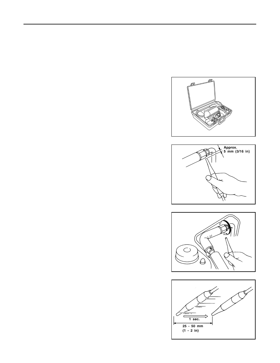
The electronic refrigerant leak detector (J-41995) is a delicate
device. To use the electronic refrigerant leak detector (J-41995)
properly, read the manufacturer's operating instructions and perform
any specified maintenance.
1.
Position the probe approximately 5 mm (3/16 in) away from the
point to be checked as shown.
2.
When checking for leaks, circle each fitting completely with the
probe as shown.
3.
Move the probe along each component at a speed of approxi-
mately 25 - 50 mm (1 - 2 in)/second as shown.
CHECKING PROCEDURE
AHA281A
SHA707EA
SHA706E
SHA708EA
2008 Titan
Revision: October 2007

ELECTRICAL LEAK DETECTOR
HA-27
< ON-VEHICLE MAINTENANCE >
C
D
E
F
G
H
J
K
L
M
A
B
HA
N
O
P
NOTE:
To prevent inaccurate or false readings, make sure there is no refrigerant vapor, shop chemicals, or cigarette
smoke in the vicinity of the vehicle. Perform the leak test in a calm area (low air/wind movement) so that the
leaking refrigerant is not dispersed.
1.
Turn the engine OFF.
2.
Connect the manifold gauge set (J-39183-C) to the A/C service ports. Refer to
.
3.
Check if the A/C refrigerant pressure is at least 345 kPa (3.52 kg/cm
2
, 50 psi) above a temperature of
16
°
C (61
°
F). If less than specification, recover/evacuate and recharge the system with the specified
amount of refrigerant. Refer to
HA-22, "HFC-134a (R-134a) Service Procedure"
.
NOTE:
At temperatures below 16
°
C (61
°
F), leaks may not be detected since the system may not reach 345 kPa
(3.52 kg/cm
2
, 50 psi) pressure.
4.
Perform the leak test from the high-pressure side (A/C compressor discharge “a” to evaporator inlet “f”) to
the low-pressure side (A/C evaporator drain hose “g” to shaft seal “k”). Refer to
Clean the component to be checked and carefully move the electronic refrigerant leak detector probe
completely around the following connections and components.
• Check the compressor shaft seal
• Check the high and low-pressure pipe and hose fittings, relief valve, and compressor shaft seal
• Check the liquid tank
• Check the refrigerant pressure sensor
• Check all around the service valves. Check that the service valve caps are screwed tightly on the ser-
vice valves (to prevent leaks).
NOTE:
After removing manifold gauge set (J-39183-C) from the service valves, wipe any residue from the ser-
vice valves to prevent any false readings by the electronic refrigerant leak detector (J-41995).
• Evaporator
With engine OFF, turn blower fan on “High” for at least 15 seconds to dissipate any refrigerant trace in
the heater and cooling unit assembly. Wait a minimum of 10 minutes accumulation time (refer to the
manufacturer's recommended procedure for actual wait time) before inserting the electronic refrigerant
leak detector probe into the heater and cooling unit assembly drain hose.
NOTE:
Keep the probe inserted for at least 10 seconds. Use caution not to contaminate the probe tip with water
or dirt that may be in the drain hose.
5.
If a leak is detected, verify at least once by blowing compressed air into the area of the suspected leak,
then repeat the leak check.
6.
Do not stop when one leak is found. Continue to check for additional leaks at all system components and
connections.
7.
If no leaks are found, perform steps 8 - 11.
8.
Start the engine.
9.
Set the heater A/C controls as follows:
NOTE:
For the automatic system, turn OFF the automatic controls and set the heater A/C controls manually.
a.
A/C switch to ON
b.
Air flow to VENT mode
c.
Intake position to RECIRCULATION mode
d.
Temperature to MAX cold
e.
Blower fan speed to HIGH
10. Run the engine at 1,500 rpm for at least 2 minutes.
2008 Titan
Revision: October 2007
HA-28
< ON-VEHICLE MAINTENANCE >
ELECTRICAL LEAK DETECTOR
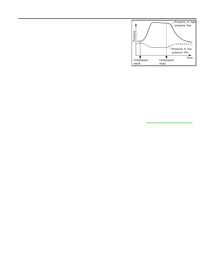
11. Turn the engine OFF and perform the leak check again following
steps 4 through 6 above.
Refrigerant leaks should be checked immediately after turning
the engine OFF. Begin with the leak detector at the compressor.
The pressure on the high pressure side will gradually drop after
the refrigerant circulation stops and pressure on the low pres-
sure side will gradually rise, as shown in the graph. Some leaks
are more easily detected when the pressure is high.
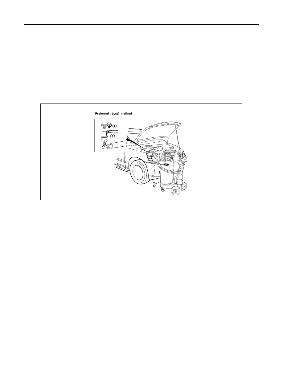
12. Before connecting the recovery/recycling equipment to the vehicle, check the recovery/recycling equip-
ment gauges. No refrigerant pressure should be displayed. If pressure is displayed, recover the refriger-
ant from the equipment lines and then check the refrigerant purity.
13. Confirm refrigerant purity in supply tank using recovery/recycling equipment and refrigerant identifier
equipment.
14. Confirm the refrigerant purity in the vehicle's A/C system using recovery/recycling equipment and refriger-
ant identifier equipment.
15. Discharge the A/C system using recovery/recycling equipment. Repair the leaking fitting or component as
necessary.
16. Evacuate and recharge the A/C system and perform the leak test to confirm that there are no refrigerant
leaks.
17. Conduct the Operational Check to ensure system works properly. Refer to
.
SHA839E
2008 Titan
Revision: October 2007
REFRIGERATION SYSTEM
HA-29
< ON-VEHICLE REPAIR >
C
D
E
F
G
H
J
K
L
M
A
B
HA
N
O
P
ON-VEHICLE REPAIR
REFRIGERATION SYSTEM
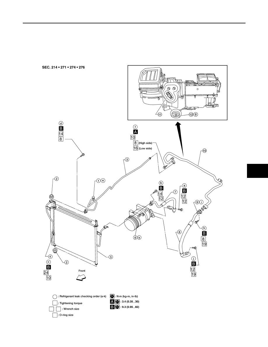
Component
INFOID:0000000001308921
A/C Compressor and Condenser
WJIA1577E
2008 Titan
Revision: October 2007
HA-30
< ON-VEHICLE REPAIR >
REFRIGERATION SYSTEM
NOTE:
Refer to
HA-5, "Precaution for Refrigerant Connection"
HFC-134a (R-134a) Service Procedure
INFOID:0000000001308922
SETTING OF SERVICE TOOLS AND EQUIPMENT
Discharging Refrigerant
WARNING:
Avoid breathing A/C refrigerant and oil vapor or mist. Exposure may irritate eyes, nose and throat.
Remove HFC-134a (R-134a) refrigerant from the A/C system using certified service equipment meeting
requirements of SAE J2210 HFC-134a (R-134a) recycling equipment or SAE J2201 HFC-134a (R-134a)
recovery equipment. If an accidental system discharge occurs, ventilate the work area before resum-
ing service. Additional health and safety information may be obtained from the refrigerant and oil man-
ufacturers.
Evacuating System and Charging Refrigerant
1.
High-pressure service valve
2.
Grommet
3.
High-pressure pipe
4.
Refrigerant pressure sensor
5.
Condenser
6.
Compressor shaft seal
7.
High-pressure flexible hose
8.
Low-pressure flexible hose
9.
Low-pressure service valve
10. Low-pressure pipe
11.
Expansion valve
12. Drain hose
1.
Shut-off valve
2.
A/C service valve
3.
Recovery/recycling equipment
WJIA0579E
2008 Titan
Revision: October 2007
REFRIGERATION SYSTEM
HA-31
< ON-VEHICLE REPAIR >
C
D
E
F
G
H
J
K
L
M
A
B
HA
N
O
P
1.
Shut-off valve
2.
A/C service valve
3.
Recovery/recycling equipment
4.
Refrigerant container (HFC-134a)
5.
Weight scale (J-39650)
6.
Evacuating vacuum pump (J-39699)
7.
Manifold gauge set (J-39183)
WJIA0580E
2008 Titan
Revision: October 2007
HA-32
< ON-VEHICLE REPAIR >
REFRIGERATION SYSTEM
*1
HA-20, "Maintenance of Oil Quantity
*3
HA-23, "Checking of Refrigerant
Leaks"
*5
HA-4, "Contaminated Refrigerant"
*2
HA-23, "Checking of Refrigerant
Leaks"
*4
HAC-86, "Performance Test Diag-
noses"
WJIA1923E
2008 Titan
Revision: October 2007
COMPRESSOR
HA-33
< ON-VEHICLE REPAIR >
C
D
E
F
G
H
J
K
L
M
A
B
HA
N
O
P
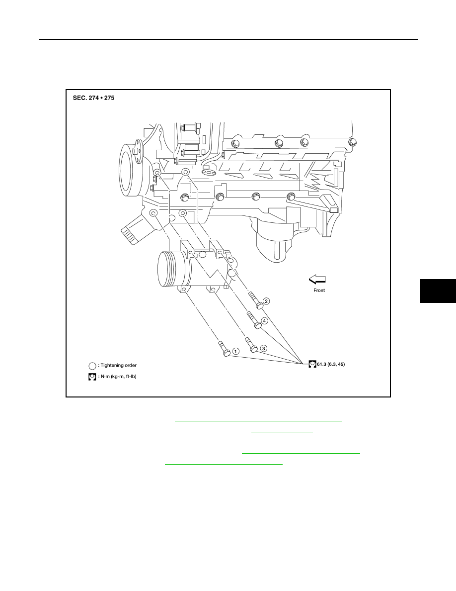
COMPRESSOR
Removal and Installation for Compressor
INFOID:0000000001308923
A/C Compressor Mounting
REMOVAL
1.
Discharge the refrigerant. Refer to
HA-30, "HFC-134a (R-134a) Service Procedure"
.
2.
Remove the front right wheel and tire assembly. Refer to
.
3.
Remove the engine under cover and the splash shield using power tool.
4.
Remove the engine air cleaner and air ducts. Refer to
EM-25, "Removal and Installation"
5.
Remove the drive belt. Refer to
EM-13, "Removal and Installation"
.
6.
Disconnect the compressor electrical connector.
7.
Disconnect the high-pressure flexible hose and low-pressure flexible hose from the compressor.
CAUTION:
Cap or wrap the joint of the pipe with suitable material such as vinyl tape to avoid the entry of air.
8.
Remove the compressor bolts and nut using power tools.
INSTALLATION
Installation is in the reverse order of removal.
CAUTION:
• Replace the O-ring of the low-pressure flexible hose and high-pressure flexible hose with a new one,
apply compressor oil to them when installing them.
WJIA0958E
2008 Titan
Revision: October 2007
HA-34
< ON-VEHICLE REPAIR >
COMPRESSOR
• After recharging the A/C system with refrigerant, check for leaks.
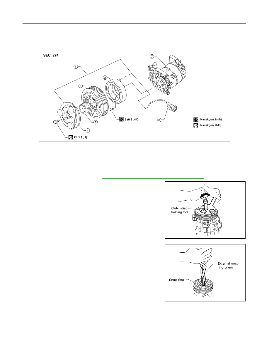
Removal and Installation for Compressor Clutch
INFOID:0000000001308924
Magnet Clutch Assembly
REMOVAL
1.
Remove the compressor. Refer to
HA-33, "Removal and Installation for Compressor"
2.
Remove the center bolt while holding the clutch disc stationary
using Tool as shown.
3.
Remove the clutch disc.
4.
Remove the snap ring using external snap ring pliers or suitable
tool.
WJIA0372E
1.
Magnet clutch assembly
2.
Magnet coil
3.
Pulley
4.
Clutch disc
5.
Snap ring
6.
Thermal protector (built in)
7.
Compressor
Tool number
: J-44614
WHA228
RHA072C
2008 Titan
Revision: October 2007
COMPRESSOR
HA-35
< ON-VEHICLE REPAIR >
C
D
E
F
G
H
J
K
L
M
A
B
HA
N
O
P
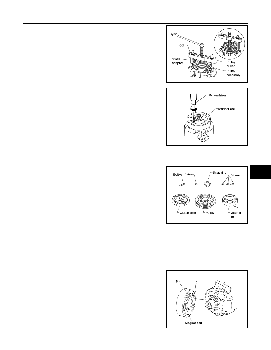
5.
Remove the pulley using Tool with a small adapter. Position the
small adapter on the end of the drive shaft and the center of the
puller on the small adapter.
CAUTION:
To prevent deformation of the pulley groove, the puller
claws should be hooked under the pulley groove and not
into the pulley groove.
6.
Remove the magnet coil harness clip using a screwdriver,
remove the three magnet coil fixing screws and remove the
magnet coil.
INSPECTION
Clutch Disc
If the contact surface shows signs of damage due to excessive heat,
replace clutch disc and pulley.
Pulley
Check the appearance of the pulley assembly. If contact surface of pulley shows signs of excessive grooving,
replace clutch disc and pulley. The contact surfaces of the pulley assembly should be cleaned with a suitable
solvent before reinstallation.
Coil
Check magnet coil for loose connections or any cracked insulation.
INSTALLATION
1.
Install the magnet coil.
CAUTION:
Be sure to align the magnet coil pin with the hole in the
compressor front head.
2.
Install the magnet coil harness clip using a screwdriver.
Tool number
: KV99233130 (J-29884)
WJIA1017E
WHA212
WHA183
WHA213
2008 Titan
Revision: October 2007
HA-36
< ON-VEHICLE REPAIR >
COMPRESSOR
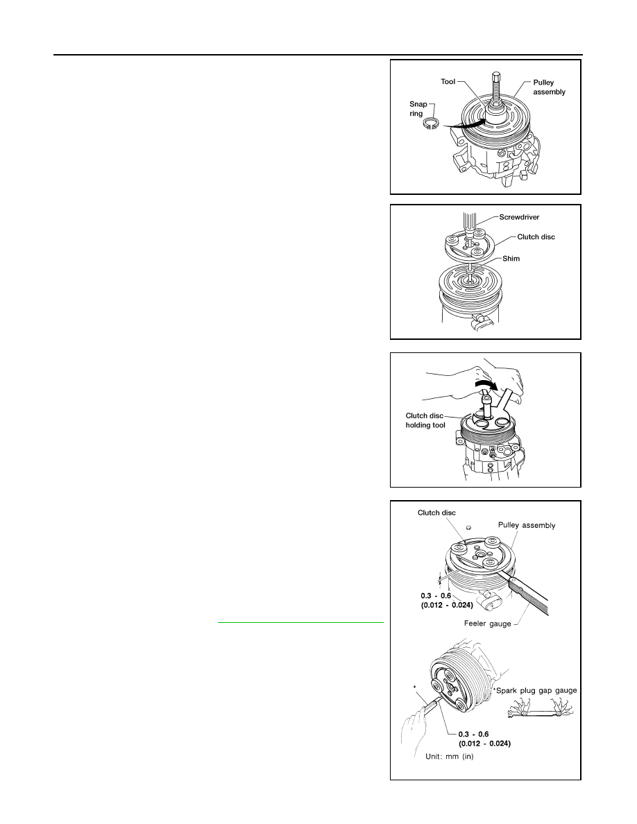
3.
Install the pulley assembly using Tool and a wrench, then install
the snap ring using snap ring pliers.
4.
Install the clutch disc on the compressor shaft, together with the
original shim(s). Press the clutch disc down by hand.
5.
Install the clutch pulley bolt using Tool, to prevent the clutch disc
from turning and tighten the bolt to specification.
CAUTION:
After tightening the clutch pulley bolt, check that the clutch
pulley rotates smoothly.
6.
Check the pulley clearance all the way around the clutch disc as
shown.
7.
If the specified clearance is not obtained, replace the adjusting
spacer to readjust.
8.
Connect the compressor electrical connector.
9.
Install the drive belt. Refer to
EM-13, "Removal and Installation"
.
10. Install the engine under cover and the splash shield.
Tool number
:
—
(J-38873-A)
WJIA1016E
WHA184
Tool number
: J-44614
WHA229
Clutch disc-to-pulley clearance
: 0.3 - 0.6 mm
(0.012 - 0.024 in)
WHA194
2008 Titan
Revision: October 2007

COMPRESSOR
HA-37
< ON-VEHICLE REPAIR >
C
D
E
F
G
H
J
K
L
M
A
B
HA
N
O
P
BREAK-IN OPERATION
When replacing compressor clutch assembly, always conduct the break-in operation. This is done by engag-
ing and disengaging the clutch about 30 times. Break-in operation raises the level of transmitted torque.
2008 Titan
Revision: October 2007

HA-38
< ON-VEHICLE REPAIR >
LOW-PRESSURE FLEXIBLE HOSE
LOW-PRESSURE FLEXIBLE HOSE
Removal and Installation for Low-Pressure Flexible Hose
INFOID:0000000001308925
REMOVAL
1.
Remove the engine room cover using power tools.
2.
Remove the engine air cleaner and air ducts. Refer to
EM-25, "Removal and Installation"
3.
Discharge the refrigerant. Refer to
HA-30, "HFC-134a (R-134a) Service Procedure"
.
CAUTION:
Cap or wrap the joint of the pipe with suitable material such as vinyl tape to avoid the entry of air.
4.
Remove the low-pressure flexible hose.
INSTALLATION
Installation is in the reverse order of removal.
Refer to
CAUTION:
• Replace the O-ring of the low-pressure flexible hose with a new one, then apply compressor oil to it
when installing it.
• After charging refrigerant, check for leaks.
2008 Titan
Revision: October 2007

LOW-PRESSURE PIPE
HA-39
< ON-VEHICLE REPAIR >
C
D
E
F
G
H
J
K
L
M
A
B
HA
N
O
P
LOW-PRESSURE PIPE
Removal and Installation for Low-Pressure Pipe
INFOID:0000000001308926
REMOVAL
1.
Discharge the refrigerant. Refer to
HA-30, "HFC-134a (R-134a) Service Procedure"
.
2.
Remove the low-pressure pipe.
CAUTION:
Cap or wrap the joint of the pipes with suitable material such as vinyl tape to avoid the entry of air.
INSTALLATION
Installation is in the reverse order of removal.
Refer to
CAUTION:
• Replace the O-ring of the high/low-pressure pipe with a new one, then apply compressor oil to it
when installing it.
• After charging refrigerant, check for leaks.
2008 Titan
Revision: October 2007

HA-40
< ON-VEHICLE REPAIR >
HIGH-PRESSURE FLEXIBLE HOSE
HIGH-PRESSURE FLEXIBLE HOSE
Removal and Installation for High-pressure Flexible Hose
INFOID:0000000001308927
REMOVAL
1.
Remove the engine under cover.
2.
Remove the engine air cleaner and air ducts. Refer to
EM-25, "Removal and Installation"
3.
Discharge the refrigerant. Refer to
HA-30, "HFC-134a (R-134a) Service Procedure"
.
4.
Remove the high-pressure flexible hose.
CAUTION:
Cap or wrap the joint of the pipe with suitable material such as vinyl tape to avoid the entry of air.
INSTALLATION
Installation is in the reverse order of removal.
Refer to
CAUTION:
• Replace the O-ring of the high-pressure flexible hose with a new one, then apply compressor oil to it
when installing it.
• After charging refrigerant, check for leaks.
2008 Titan
Revision: October 2007

HIGH-PRESSURE PIPE
HA-41
< ON-VEHICLE REPAIR >
C
D
E
F
G
H
J
K
L
M
A
B
HA
N
O
P
HIGH-PRESSURE PIPE
Removal and Installation for High-pressure Pipe
INFOID:0000000001308928
REMOVAL
1.
Disconnect the battery negative terminal and battery positive terminal.
2.
Reposition the IPDM E/R aside.
3.
Remove the front right wheel and tire assembly. Refer to
.
4.
Position aside the front floor insulator.
5.
Discharge the refrigerant. Refer to
HA-30, "HFC-134a (R-134a) Service Procedure"
.
6.
Remove the low pressure pipe.
7.
Remove the high-pressure pipe.
CAUTION:
Cap or wrap the joint of the pipe with suitable material such as vinyl tape to avoid the entry of air.
INSTALLATION
Installation is in the reverse order of removal.
Refer to
CAUTION:
• Replace the O-ring of the high-pressure pipe with a new one, then apply compressor oil to it when
installing it.
• After charging refrigerant, check for leaks.
2008 Titan
Revision: October 2007
HA-42
< ON-VEHICLE REPAIR >
CONDENSER
CONDENSER
Removal and Installation for Condenser
INFOID:0000000001308929
REMOVAL
1.
Discharge the refrigerant. Refer to
HA-30, "HFC-134a (R-134a) Service Procedure"
.
2.
Remove the radiator. Refer to
CO-15, "Removal and Installation"
.
CAUTION:
Be careful not to damage the core surface of the condenser and the radiator.
3.
Disconnect the high-pressure flexible hose and the high-pressure pipe from the condenser.
CAUTION:
Cap or wrap the joint of the pipe with suitable material such as vinyl tape to avoid the entry of air.
4.
Disconnect the refrigerant pressure sensor connector.
• Remove the refrigerant pressure sensor from the condenser
as necessary.
5.
Lift the condenser out of the mounting grommets to remove the
condenser.
INSTALLATION
Installation is in the reverse order of removal.
Refer to
CAUTION:
• Replace the O-rings of the high-pressure pipe, refrigerant pressure sensor, and high-pressure flexi-
ble hose with new ones, then apply compressor oil to them when installing them.
• After charging refrigerant, check for leaks.
• Replace the grommets as necessary.
LJIA0145E
2008 Titan
Revision: October 2007
REFRIGERANT PRESSURE SENSOR
HA-43
< ON-VEHICLE REPAIR >
C
D
E
F
G
H
J
K
L
M
A
B
HA
N
O
P
REFRIGERANT PRESSURE SENSOR
Removal and Installation for Refrigerant Pressure Sensor
INFOID:0000000001308930
REMOVAL
1.
Discharge the refrigerant. Refer to
HA-30, "HFC-134a (R-134a) Service Procedure"
.
2.
Disconnect the refrigerant pressure sensor electrical connector
and remove the refrigerant pressure sensor from the condenser.
CAUTION:
Be careful not to damage the condenser fins.
INSTALLATION
Installation is in the reverse order of removal.
Refer to
CAUTION:
• Be careful not to damage the condenser fins.
• Replace the O-ring of the refrigerant pressure sensor with a new one, then apply compressor oil to it
when installing it.
• After charging refrigerant, check for leaks.
LJIA0145E
2008 Titan
Revision: October 2007
HA-44
< ON-VEHICLE REPAIR >
EXPANSION VALVE
EXPANSION VALVE
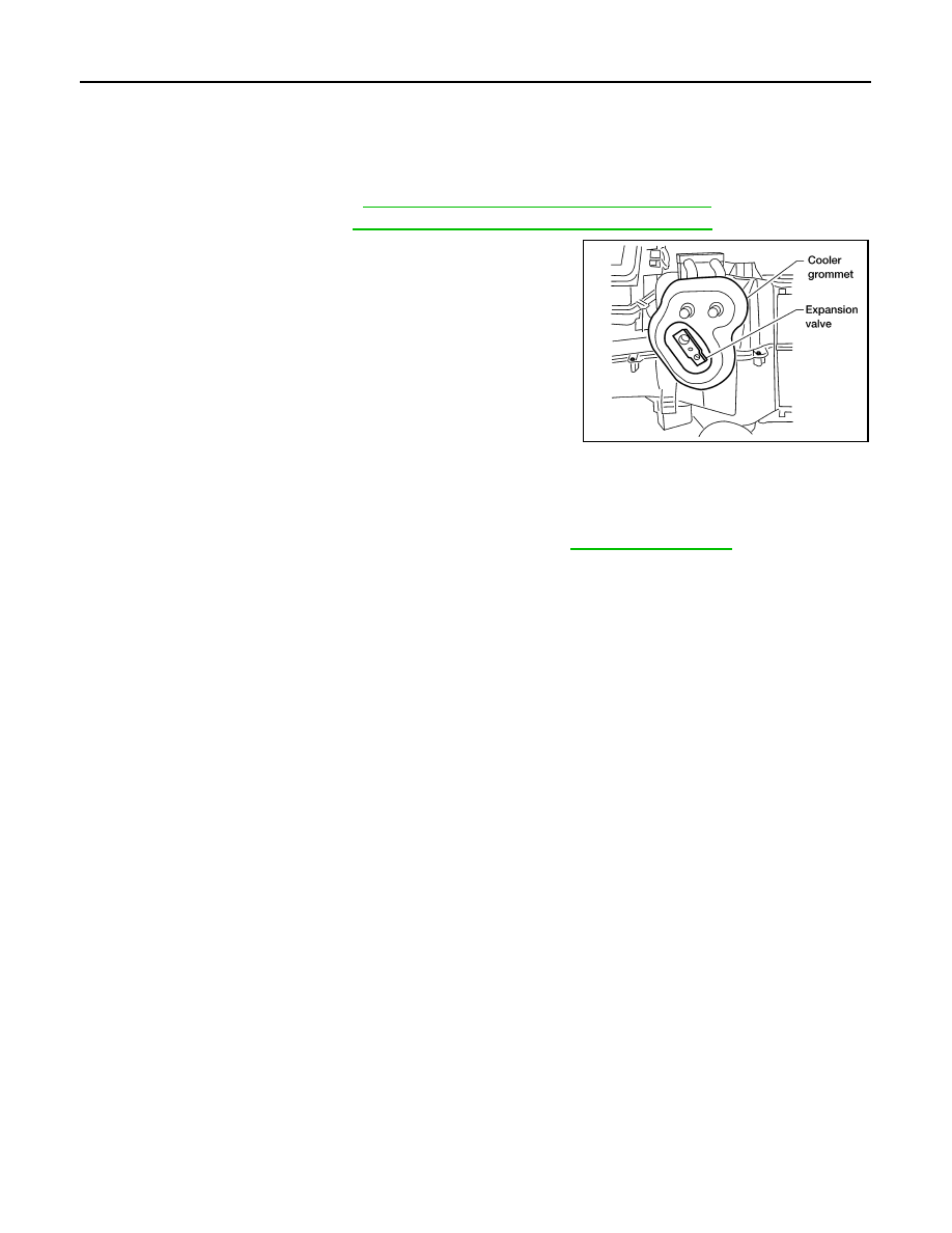
Removal and Installation for Expansion Valve
INFOID:0000000001308931
REMOVAL
1.
Discharge the refrigerant. Refer to
HA-30, "HFC-134a (R-134a) Service Procedure"
.
2.
Remove the evaporator. Refer to
VTL-27, "Removal and Installation for Evaporator"
.
3.
Remove the cooler grommet.
4.
Remove the expansion valve.
INSTALLATION
Installation is in the reverse order of removal.
CAUTION:
• Replace the O-rings on the A/C refrigerant pipes with new ones, then apply compressor oil to them
when installing them.
• After charging refrigerant, check for leaks.
WJIA0582E
Expansion valve bolts
: 4 N·m (0.41 kg-m, 35 in-lb)
A/C refrigerant pipe to expansion valve bolt
: Refer to
2008 Titan
Revision: October 2007
AMBIENT SENSOR
HA-45
< ON-VEHICLE REPAIR >
C
D
E
F
G
H
J
K
L
M
A
B
HA
N
O
P
AMBIENT SENSOR
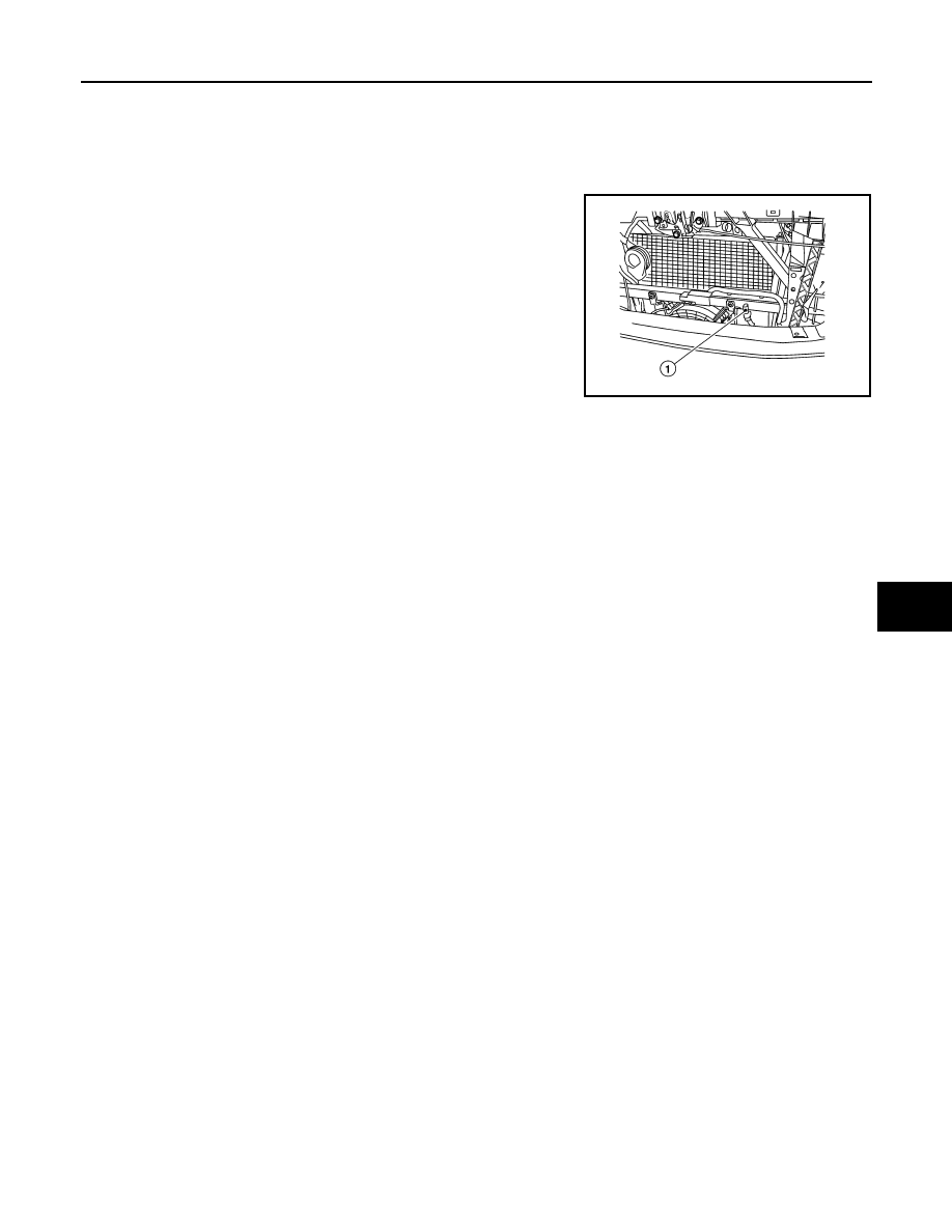
Removal and Installation
INFOID:0000000001308920
REMOVAL
1.
Disconnect the ambient sensor electrical connector.
NOTE:
The ambient sensor (1) is located behind the front bumper, in
front of the condenser.
2.
Release the ambient sensor clip and then remove the ambient
sensor (1).
INSTALLATION
Installation is in the reverse order of removal.
AWIIA0238ZZ
2008 Titan
Revision: October 2007

HA-46
< SERVICE DATA AND SPECIFICATIONS (SDS)
SERVICE DATA AND SPECIFICATIONS (SDS)
SERVICE DATA AND SPECIFICATIONS (SDS)
SERVICE DATA AND SPECIFICATIONS (SDS)
Service Data and Specification (SDS)
INFOID:0000000001308888
COMPRESSOR
OIL
REFRIGERANT
Make
ZEXEL VALEO CLIMATE CONTROL
Model
DKS-17D
Type
Swash plate
Displacement
175.5 cm
3
(10.7 in
3
) / revolution
Cylinder bore
×
stroke
30.5 mm (1.20 in) x 24.0 mm (0.94 in)
Direction of rotation
Clockwise (viewed from drive end)
Drive belt
Poly V
Name
NISSAN A/C System Oil Type S (DH-PS)
Part number
KLH00-PAGS0
Capacity
200 m
(6.8 US fl oz, 7.0 Imp fl oz)
Type
HFC 134a (R-134a)
Capacity
0.70
±
0.05 kg (1.54
±
0.11 lb)
2008 Titan
Revision: October 2007
Document Outline
- QUICK REFERENCE INDEX
- Table of Contents
- PRECAUTION
- PRECAUTIONS
- Precaution for Supplemental Restraint System (SRS) "AIR BAG" and "SEAT BELT PRE-TENSIONER"
- Precaution for Working with HFC-134a (R-134a)
- Precaution for Procedure without Cowl Top Cover
- Contaminated Refrigerant
- General Refrigerant Precaution
- Precaution for Leak Detection Dye
- A/C Identification Label
- Precaution for Refrigerant Connection
- Precaution for Service of Compressor
- Precaution for Service Equipment
- PRECAUTIONS
- PREPARATION
- FUNCTION DIAGNOSIS
- ON-VEHICLE MAINTENANCE
- ON-VEHICLE REPAIR
- SERVICE DATA AND SPECIFICATIONS (SDS)
- PRECAUTION
Wyszukiwarka
Podobne podstrony:
HA ja na ARA cwiczenia 2010
ha
Materia�y do wyk�ad�w z ha�asu
iv rok - ryby - wejsciowka 2, Wapnowanie Ca nawozowe 95% CaCO3 200-400kg/ha lub Ca palone 85%CaO 500
HA, HA opracowanie 2
Dla słabego kwasu HA, Towaroznawstwo SGGW, Rok I, Semestr I, Chemia nieorganiczna
Brecht?rtolt Vaterlandsliebe,?r Haß gegen Vaterländer
Obsluga elektromechanicznego ha Nieznany
2011 KRYZA HA ok 20slid 27448 ppt
ha 317e
HA üAS I WIBRACJE W ÜRODOWISKU prom
ryby 2, Wapnowanie Ca nawozowe 95% CaCO3 200-400kg/ha lub Ca palone 85%CaO 500-600kg/ha wapnuje się
Akumulator do HANOMAG HA HA15 HA19
02 Zalecenia HA
ha
Bertolt Brecht Vaterlandsliebe,?r Haß gegen Vaterländer
HA AS, Inne
HA 2
więcej podobnych podstron