
See discussions, stats, and author profiles for this publication at:
http://www.researchgate.net/publication/267218541
MATHEMATICAL AND TECHNICAL OPTIMA IN
THE DESIGN OF WELDED STEEL SHELL
ARTICLE
DOWNLOADS
30
VIEWS
6
1 AUTHOR:
73
PUBLICATIONS
193
CITATIONS
Available from: József Farkas
Retrieved on: 16 June 2015

MATHEMATICAL AND TECHNICAL OPTIMA IN THE DESIGN
OF WELDED STEEL SHELL STRUCTURES
J. Farkas
*, †
University of Miskolc, H-3515 Miskolc, Hungary
ABSTRACT
In some cases the optimum is the minimum of the objective function (mathematical
optimum), but in other cases the optimum is given by a technical constraint (technical
optimum). The present paper shows the both types in two problems. The first problem is to
find the optimum dimensions of a ring-stiffened circular cylindrical shell subject to external
pressure, which minimize the structural cost. The calculation shows that the cost decreases
when the shell diameter decreases. The decrease of diameter is limited by a fabrication
constraint that the diameter should be minimum 2 m to make it possible the welding and
painting inside of the shell. The second problem is to find the optimum dimensions of a
cantilever column loaded by compression and bending. The column is constructed as
circular or conical unstiffened shell. The cost comparison of both structural versions shows
the most economic one.
Received: February 2011; Accepted: June 2011
KEY WORDS: structural optimization, circular and conical cylindrical shells, cost
calculation, buckling of plates and shells, economy of welded structures
1. INTRODUCTION
Cylindrical shells are used in various engineering structures, e.g. in pipelines, offshore
structures, columns and towers, bridges, silos etc. The shells can be stiffened against
buckling by ring-stiffeners or stringers or orthogonally. The effectiveness of stiffening
depends on the kind of load. Many cases of loads and stiffening have been investigated by
realistic numerical structural models and design aspects have been concluded by cost
comparisons of optimized structural versions [1-3].
*
Corresponding author: J. Farkas, University of Miskolc, H-3515 Miskolc, Hungary
†
E-mail address: altfar@uni-miskolc.hu
INTERNATIONAL JOURNAL OF OPTIMIZATION IN CIVIL ENGINEERING
Int. J. Optim. Civil Eng., 2011; 1:141-153

J. Farkas
142
Since in Eurocodes design method for stiffened shell buckling is not given, the design
rules of Det Norske Veritas (DNV) are used. In this new investigation newer DNV shell
buckling formulae are applied [4].
Optimum design of ring-stiffened cylindrical shells has been treated in [5,6]. Results of
model experiments for cylindrical shells used in offshore oil platforms have been published
in [7]. In [8] the proposed strength formulation is compared with DNV rules, British
Standard BS 5500 and experimental results.
The tripping of open section ring-stiffeners is treated in [9]. Buckling solutions for shells
with various end conditions, stiffener distributions and under various pressure distributions
have been presented in [10,11].
In [12] the adopted approach aims at simultaneously minimizing the shell vibration,
associated sound radiation, weight of the stiffening rings as well as the cost of the stiffened
shell. The production, life cycle and maintenance costs are computed using the Parametric
Review of Information for Costing and Evaluation (PRICE) model (Price Systems, N.J.
Mount Laurel, 1999) without any detailed cost data.
In the optimization process the optimum values of shell diameter and thickness as well as
the number and dimensions of ring-stiffeners are sought to minimize the structural volume
or cost. In order to avoid tripping welded square box section stiffeners are used, their side
length and thickness of plate elements should be optimized.
Besides the constraints on shell and stiffener buckling the fabrication constraints can be
active. To make it possible the welding of stiffeners inside the shell the minimum shell
diameter should be fixed (2000 mm). The calculations show that the volume and cost
decreases when the shell diameter is decreased. Thus, the shell diameter can be the fixed
minimum value. Another fabrication constraint is the limitation of shell and plate thickness
(4mm).
The remaining unknown variables can be calculated using the two buckling constraints
and the condition of volume or cost minimization. The relation between the side length and
plate thickness of ring-stiffeners is determined be the local buckling constraint. To obtain
the optimum values of variables a relative simple systematic search method is used.
The cost function contains the cost of material, assembly, welding and painting and is
formulated according to the fabrication sequence.
Columns or towers are used in many engineering structures, e.g. in buildings, wind
turbine towers, piers of motorways, etc. They can be constructed as rectangular boxes or
shells. Walls of boxes can be designed from stiffened plates or cellular plates. Shells can be
unstiffened or stiffened circular or conical. A ring-stiffened conical shell is treated for
external pressure in the case of equidistant and non-equidistant stiffening in [3, 13].
Previous studies have shown that, when the constraint on horizontal displacement of the
column top is not active, the unstiffened circular shell can be cheaper than that of stringer
stiffened one. In the present study the unstiffened circular shell is compared to the slightly
conical one to show the economy of conical shells over the circular ones.
In previous studies the fabrication has been realized by using 3 m long plate elements to
form unstiffened shell elements. In the present study 1.5 m wide plate elements are used.
Therefore, the shell thicknesses can be varied in more shell parts. With equidistant shell
elements of the same thickness the fabrication can be realized more easily.
MATHEMATICAL AND TECHNICAL OPTIMA IN THE DESIGN...
143
The optimal thickness for each shell element is calculated from the shell buckling
constraint according to the Det Norske Veritas [4] design rules.
In the previous studies the fabrication sequence is designed so that the circumferential
welds have been realized for the completely assembled shell. In order to ease the welding
inside the shell the fabrication is changed and it is supposed that these welds are welded
successively. Thus the next 1.5 m wide shell part is welded to the previous longer structure
and so the number of assembled parts is always 2.
Firstly, the conical shell is optimized by using different radii with a constant inclination
angle. Secondly, this angle is changed to show its effect. Thirdly, the optimal circular shell
radius is sought to minimize the cost.
2. RING-STIFFENED CYLINDRICAL SHELL LOADED BY EXTERNAL
PRESSURE
2.1. Characteristics of the optimization problem
Given data: external pressure intensity p = 0.5 N/mm
2
, safety factor γ = 1.5, shell length L
= 6000 mm, steel yield stress f
y
= 355 MPa, elastic modulus E = 2.1
10
5
MPa, Poisson ratio
ν = 0.3, density ρ = 7.85
10
-6
kg/mm
3
, the cost constants are given separately.
Unknown variables: shell radius R, shell thickness t, number of spacings between ring-
stiffeners n, thus, the spacing between stiffeners is L
r
= L/n, the side length of the square box
section stiffener h
r
, the thickness of stiffener plate parts t
r
.
2.2. Constraint on shell buckling
According to the DNV rules [4]
E
y
y
f
f
t
pR
,
1
4
(1)
2
2
2
1
12
r
E
L
t
E
C
(2)
6
.
0
,
4
,
1
1
2
1
C
(3)
2
2
1
,
04
.
1
Rt
L
Z
Z
r
(4)
2.3. Constraint on ring-stiffener buckling
The moment of inertia of the effective stiffener cross-section should be larger than the
J. Farkas
144
required one
req
x
I
I
(5)
The effective shell length between ring-stiffeners is the smaller of
R
t
Rt
L
e
12
1
56
.
1
or L
r
(6)
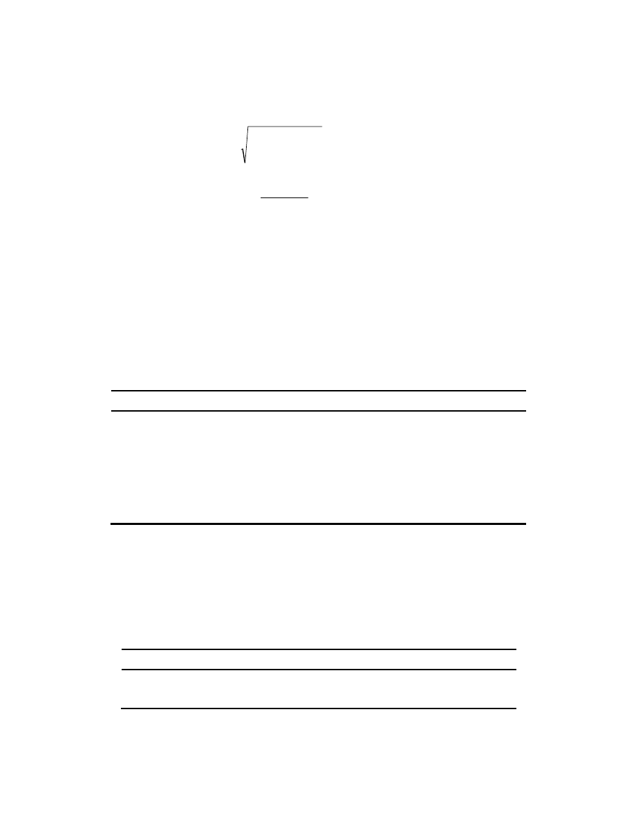
The distance of the gravity centre of the effective ring-stiffener cross-section (Figure 1)
t
L
h
t
t
h
t
h
t
t
h
t
L
y
e
r
r
r
r
r
r
r
r
e
E
3
2
(7)
The moment of inertia of the effective stiffener cross-section
2
3
2
2
3
2
12
2
2
6
E
r
r
e
e
E
r
r
E
r
r
r
r
r
r
x
y
t
t
h
t
L
t
L
y
t
h
y
t
h
h
t
h
t
I
(8)
The relation between h
r
and t
r
is determined by the local buckling constraint
y
r
r
f
h
t
235
,
42
1
,
(9)
For f
y
= 355
34
/
1
, the required t
r
is rounded to the larger integer, but t
rmin
= 4 mm.
The required moment of inertia
2
005
.
0
3
5
.
1
3
2
0
2
0
y
E
r
req
f
R
R
Ey
E
L
pRR
I
(10)
MATHEMATICAL AND TECHNICAL OPTIMA IN THE DESIGN...
145
R
0
a
w
E
x
Figure 1. Ring-stiffened cylindrical shell loaded by external pressure
2.4. The cost function
The cost function contents the cost of material, assembly, welding and painting and is
formulated according to the fabrication sequence.
The cost of assembly and welding is calculated using the following formula [1-3]
i
wi
pi
n
wi
wi
w
w
L
C
a
C
V
C
k
K
3
.
1
1
(11)
where k
w
[$/min] is the welding cost factor, C
1
is the factor for the assembly usually taken as
C
1
= 1 min/kg
0.5
, Θ is the factor expressing the complexity of assembly, the first member
calculates the time of the assembly, κ is the number of structural parts to be assembled, ρV
is the mass of the assembled structure, the second member estimates the time of welding,
C
w
and n are the constants given for the specified welding technology and weld type, C
p
is
the factor of welding position (for downhand 1, for vertical 2, for overhead 3), L
w
is the weld
length, the multiplier 1.3 takes into account the additional welding times (deslagging,
chipping, changing the electrode).
The fabrication sequence is as follows:
(a) Welding the unstiffened shell from curved plate parts of dimensions 6000
1500 mm
and of number
1500
2
R
n
p
,
which should be rounded to the larger integer. Use butt welds of length
L
w1
= n
p
L,
1
,
2
,
,
3
1
1
W
p
k
Lt
R
V
n
, (12)
welding technology SAW (submerged arc welding)
J. Farkas
146
For
t = 4−15 mm C
W1
= 0.1346
10
-3
and n
1
= 2,
(13a)
for
t > 15 mm C
W1
= 0.1033
10
-3
and n
1
= 1.9,
(13b)
1
1
1
1
1
1
3
.
1
W
n
W
W
W
L
t
C
V
k
K
(14)
(b) Welding the ring-stiffeners separately from 3 plate parts with 2 fillet welds
(GMAW-C – gas metal arc welding with CO
2
):
2
2
3
2
2
10
3394
.
0
3
.
1
3
W
W
W
W
L
a
x
x
V
k
K
(15)
where
r
r
r
r
r
r
h
R
t
h
h
R
t
h
V
2
2
4
2
(16)
r
W
r
W
t
a
h
R
L
7
.
0
,
4
2
(17)
(c) Welding the (n+1) ring-stiffeners into the shell with 2 circumferential fillet welds
(GMAW-C)
3
2
3
3
3
10
3394
.
0
3
.
1
2
W
W
W
W
L
a
x
x
V
n
k
K
(18)
where
1
4
,
1
3
2
1
3
n
R
L
V
n
V
V
W
(19)
Material cost
1
,
3
M
M
M
k
V
k
K
$/kg
(20)
Painting cost
6
10
8
.
28
,
x
k
S
k
K
P
P
P
P
$/mm
2
, (21)
1
2
4
1
2
1
2
2
n
h
h
R
n
h
h
R
h
n
L
R
L
R
S
r
r
r
r
r
P
(22)
The total cost
P
W
W
W
M
K
K
K
n
K
K
K
3
2
1
1
(23)
2.5. Results of the optimization
In the following the minimum cost design is obtained by a systematic search using a
MathCAD algorithm.
For a shell thickness t the number of stiffeners n is determined by the shell buckling
constraint (Eq. (1)) and the stiffener dimensions (h
r
and t
r
) are determined by the stiffener
buckling constraint (Eq. (5)).
The search results for R = 1851 and 1500 (Tables 1 and 2) show that the volume and cost
MATHEMATICAL AND TECHNICAL OPTIMA IN THE DESIGN...
147
decreases when the radius is decreased. Thus, the realistic optimum can be obtained by
taking the radius as small as possible. This minimum radius is determined by the
requirement that the internal stiffeners should easily be welded inside of shell, i.e. R
min
=
1000 mm. Therefore the more detailed search is performed for this radius (Table 3).
Table 1. Systematic search for R = 1850 mm. Dimensions are in mm. The minimum cost is
marked by bold letters
t n σ<σ
adm
MPa
h
r
t
r
I
x
>I
req
10
-4
mm
4
V
10
-5
mm
3
K $
11 7 126<152 180 6
3352>3341
10490
18770
12 6 115<143 180 6
3530>3502
10830
18640
13 5 106<124 190 6
4245>4014
11290
18650
14 4 99<109 200 6
5050>4888
11710
18620
15 4 92<121 200 6
5252>4718
12400
19390
Table 2. Systematic search for R = 1500 mm. Dimensions are in mm. The minimum cost is
marked by bold letters
t n σ<σ
adm
MPa
h
r
t
r
I
x
>I
req
10
-4
mm
4
V
10
-5
mm
3
K $
8 10 140<157 160 5
1745>1616
6830
13890
9 8 125<140 160 5
1590>1550
6870
13250
10 6 112<115 160 5
1995>1885
7130
12900
11 5 102<106 150 5
2109>2102
7480
12950
12 5 93<120 160 5
2217>2003
8050
13570
Table 3. Systematic search for R = 1000 mm. Dimensions are in mm. The optima are marked by
bold letters
t n σ<σ
adm
MPa
h
r
t
r
I
x
>I
req
10
-4
mm
4
V
10
-5
mm
3
K $
5 16 150<156 110 4
402>364
3192
8338
6 12 125<141 100 4
353>296
3177
7631
7 9 107<123 100 4
387>336
3343
7321
8 7 94<111 100 4
419>400
3579
7244
9 5 83<90 110 4
572>557
3854
7221
10 4
75<82 120 4
759>703
4186
7419
11 3
68<69 130 4
982>953
4505
7598
J. Farkas
148
It can be seen from Table 3. that the optima for minimum volume and minimum cost are
different. It is caused by the larger value of fabrication (welding and painting) cost. The
details of the cost for K = 7221 $ are given in Table 4. (The sum of the welding and painting
costs is 4196 $).
Table 4. Details of the minimum cost in $.
K
M
K
W1
(n+1)K
W2
K
W3
K
P
K
3025 673
474
665 2384 7221
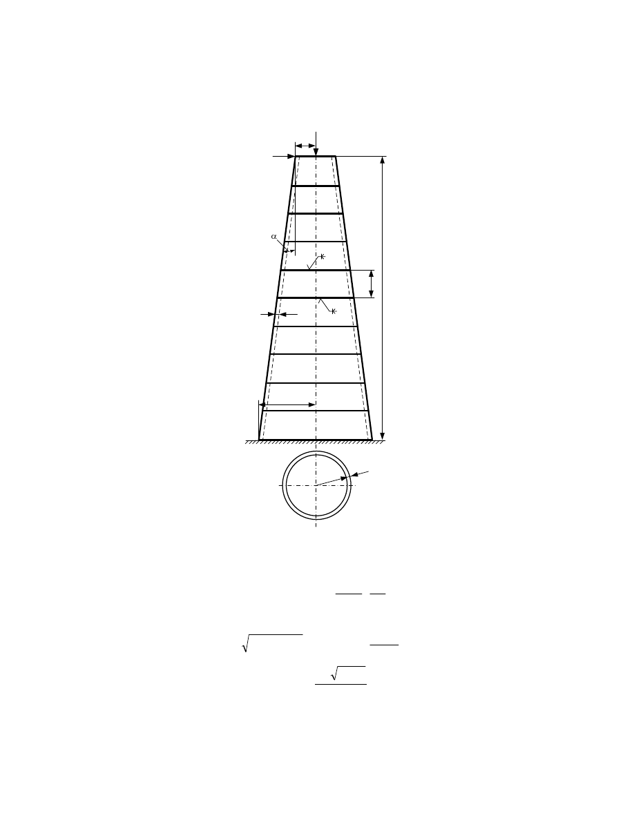
3. CIRCULAR AND CONICAL SHELLS FOR A CANTILEVER COLUMN
LOADED BY AXIAL COMPRESSION AND BENDING
3.1. Constraint on conical shell buckling
According to the DNV rules [4] the buckling of conical shells is treated like buckling of an
equivalent circular cylindrical shell.
The thickness, the average radius and the length of the i
th
equivalent shell part are
cos
2
,
cos
1
i
i
eai
i
ei
R
R
R
t
t
,
cos
i
ei
L
L
,
(24)
The inclination angle is defined by
0
0
max
tan
L
R
R
(25)
The sum of the axial and bending stresses should be smaller than the critical buckling
stress
4
2
1
0
1
2
2
i
y
cri
ei
i
i
j
i
j
F
ei
i
F
bi
ai
f
t
R
L
L
H
t
R
N
(26)
where the reduced slenderness
Ebi
bi
Eai
ai
bi
ai
y
i
f
2
(27)
MATHEMATICAL AND TECHNICAL OPTIMA IN THE DESIGN...
149
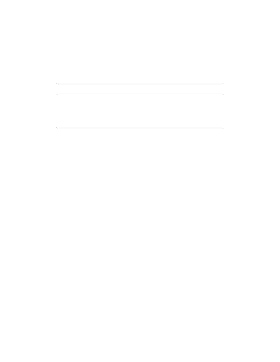
L
0
L
i
R
0
N
F
H
F
R
max
t
i
R
i
R
i+1
R
i
t
i
Figure 2. Conical shell cantilever column loaded by axial compression and bending
The elastic buckling stress for the axial compression is
2
2
92
.
10
50
5
.
1
ei
ei
ai
Eai
L
t
E
C
(28)
5
.
0
2
150
1
5
.
0
,
1
ei
eai
ai
i
ai
ai
t
R
C
(29)
3
.
0
,
1
,
702
.
0
2
2
ei
eai
ei
i
i
i
t
R
L
Z
Z
(30)
J. Farkas
150
The elastic buckling stress for bending is
2
2
92
.
10
50
5
.
1
ei
ei
bi
Ebi
L
t
E
C
(31)
5
.
0
2
300
1
5
.
0
,
1
ei
eai
bi
i
bi
bi
t
R
C
(32)
Note that the residual welding distortion factor is
1.5 50
1
when t > 9 mm. The
detailed derivation of it is treated in [2].
3.2. The cost function
The cost function contains the cost of material, forming of plate parts into conical or circular
shell elements, welding and painting and is formulated according to the fabrication
sequence.
The material cost is given by
0
.
1
,
M
M
M
k
V
k
K
$/kg, ρ = 7.85
10
-6
kg/mm
3
(33)
10
1
2
i
i
ei
eai
t
L
R
V
(34)
The cost of forming of plate parts into conical or circular shell elements
,
10
1
i
F
F
i
e
k
K
5
.
0
5
.
0
2
009531996
.
0
52721
.
4
8582513
.
6
eai
i
i
R
t
(35)
The coefficient for the complexity of assembly is
.
3
The specific fabrication cost
factor is taken as k
F
= 1.0$/min.
For a shell element 3 axial butt welds are needed (GMAW-C – Gas Metal Arc Welding
with CO
2
)
ei
i
i
F
i
W
L
t
x
x
V
k
K
3
10
152
.
0
3
.
1
94
.
1
3
0
(36)
The number of assembled elements is
.
3
Cost of welding of circumferential welds between shell elements. The welding is
performed successively, so one weld is connecting only two parts in each fabrication step.
MATHEMATICAL AND TECHNICAL OPTIMA IN THE DESIGN...
151
i
i
i
i
j
j
F
Wi
R
t
x
x
V
V
k
K
2
10
152
.
0
3
.
1
2
94
.
1
3
1
1
(37)
Cost of painting
6
0
0
max
10
8
.
28
,
2
4
x
k
L
R
R
k
K
P
P
P
$/mm
2
. (38)
The total cost
P
i
Wi
i
i
W
F
M
K
K
K
K
K
K
10
1
10
1
0
(39)
3.3. Numerical data and results
L
0
= 15 m, this height is divided in 10 shell parts, each length of L
i
= 1500 mm. This
uniform length is selected for easy fabrication. N
F
= 3400 kN, H
F
= 0.1N
F
, f
y
= 355 MPa, E =
2.1
10
5
MPa.
The calculation is performed by using a MathCAD algorithm. Results are given in Tables
5, 6 and 7.
Table 5. Cost parts ($) of conical shells of inclination angle 2.86
0
for different radii (mm)
R
0
R
max
K
M
K
F0
K
W0
K
W
K
P
K
750 1500 26300 19895 9702 14750 6107 76754
850 1600 25660 19360 8300 13753 6650 73723
1050 1800 24750
18492 6536 12300 7736 69814
1250 2000 24790 17974 5664 11796 8822 69046
1450 2200 25320 17709 5191 11640 9907 69767
1650 2400 26090 17565 4881 11754 10990 71280
In Table 5 the minimum material cost (volume) and total cost are marked by bold letters.
It can be seen that the minimum volume and minimum cost correspond to different radii.
This difference is caused by high fabrication costs. The optimum is found, since the
decrease of radii causes increase of thicknesses, which increases the material and welding
cost, on the other hand the increase of radii causes increase of material and painting cost.
Table 6. Cost parts ($) of conical shells of different inclination angles (the average radius is
1625 mm)
Angle
R
0
R
max
K
M
K
F0
K
W0
K
W
K
P
K
4.38
0
1050 2200 24870 17961 5676 11582 8822 68911
6.65
0
750 2500 25160 18246 5920 11424 8822 69572
J. Farkas
152
The thicknesses for the optimal conical shell of inclination angle 4.38
0
are from above as
follows: 18, 19, 20 and all others 21 mm.
Table 7. Cost parts ($) of circular shells for different radii. The minimum cost is
marked by bold letters
R
0
= R
max
K
M
K
F0
K
W0
K
W
K
P
K
1450 25750 18661 7070 13640 7872 72993
1650 25500 17960 5825 12393 8957 70635
1750 25500 17920 5596 12385 9500 70901
1850 25730 17809 5333 12250 10040 71162
The thicknesses for the optimal circular shell of radius 1650 mm are as follows:
14,15,17,18,20,21,23,24,26,27 mm.
4. CONCLUSIONS
In the first problem, the structural volume and the cost decrease when the shell radius is
decreased. Thus, the shell radius should be taken as small as possible. The minimum radius
is determined by the fact that the internal ring-stiffeners should welded into the shell (R
min
=
1000 mm).
The shell thickness and the number of ring-stiffeners can be calculated using the
constraint on shell buckling. In order to avoid ring-stiffener tripping, welded square box
section rings are used. The dimensions of the rings can be determined from the constraint on
ring-stiffener buckling. The constraints on buckling are formulated according to the newer
DNV design rules.
In the cost function the costs of material, assembly, welding and painting are formulated.
The welding cost parts are calculated according to the fabrication sequence. The optima for
minimum volume and minimum cost are different, since the fabrication cost parts are
relative high as compared to the whole cost.
The ring-stiffening is very effective, since in the case of n = 1 (only 2 end stiffeners) the
required shell thickness is t = 18 mm, the volume is V = 7144
10
-3
mm
3
and the cost is K =
10450$, i.e. the cost savings achieved by ring-stiffeners is (10450−7221)/10450
100 = 31%.
In the second problem, the following fabrication aspects are considered: the change of
shell thickness is designed in equal distances, the circumferential welds are welded
successively to ease the welding inside of the shell, only integer numbers are used for shell
thicknesses.
The structural volume or components of cost vary with radii in such manner that for both
circular or conical unstiffened shells optimum radius can be found.
Three inclination angles of conical shell have been investigated and one of them was
optimal.

MATHEMATICAL AND TECHNICAL OPTIMA IN THE DESIGN...
153
The comparison of conical and circular shells shows that the cost of optimal conical shell
is lower than that of circular one, but the difference is not very large (70635-68911)/
70635x100= 2.8%.
Acknowledgements: The research was supported by the Hungarian Scientific Research
Fund OTKA T-75678 and by the TÁMOP 4.2.1.B-10/2/KONV entitled “Increasing the
quality of higher education through the development of research and innovation program” at
the University of Miskolc.
REFERENCES
1.
Farkas J, Jármai K. Analysis and Optimum Design of Metal Structures, Rotterdam,
Brookfield, Balkema, 1997.
2.
Farkas J, Jármai K. Economic Design of Metal Structures, Rotterdam, Millpress,
2003.
3.
Farkas J, Jármai K. Design and Optimization of Metal Structures, Chichester, UK,
Horwood Publishing, 2008.
4.
Det Norske Veritas: Buckling strength of shells. Recommended practice DNV-RP-
C202. Høvik, Norway, 2002.
5.
Pappas M, Allentuch A. Extended capability for automate design of frame-stiffened
submersible cylindrical shells. Comput Struct 1974; 4(5): 1025-59.
6.
Pappas M, Moradi J. Optimal design of ring-stiffened cylindrical shells using multiple
stiffener sizes. AIAA J 1980; 18(8): 1020-22.
7.
Harding JE. Ring-stiffened cylinders under axial and external pressure loading. Proc.
Inst Civil Eng Part 2. 1981; 71: 863-78.
8.
Cho SR, Frieze PA. Strength formulation for ring-stiffened cylinders under combined
axial loading and radial pressure. J. Construct Steel Res 1988; 9: 3-34.
9.
Huang J, Wierzbicki T. Plastic tripping of ring stiffeners. J Struct Eng ASCE 1993;
119(5): 1622-42.
10. Wang CM, Swaddiwudhipong S, Tian J. Buckling of cylindrical shells with general
ring-stiffeners and lateral pressure distributions. Proceedings of the Seventh
International Conference on Computing in Civil and Building Engineering, Vol. 1.
Eds. Choi Ch-K. et al. Seoul, Korea 1997, pp. 237-242.
11. Tian J, Wang CM, Swaddiwudhipong S. Elastic buckling analysis of ring-stiffened
cylindrical shells under general pressure loading via the Ritz method. Thin-Walled
Struct 1999; 35: 1-24.
12. Akl W, Ruzzen M, Baz A. Optimal design of underwater stiffened shells. Struct
Multidisc Optim 2002; 23: 297-310.
13. Farkas J, Jármai K. Minimum cost design of a conical shell – External pressure, non-
equidistant stiffening. Proceedings of the Eurosteel 2008 5th European Conference on
Steel and Composite Structures Graz Austria. Eds R. Ofner et al. Brussels, ECCS
European Convention for Constructional Steelwork, 2008. Vol. B, pp. 1539-1544.
Wyszukiwarka
Podobne podstrony:
Mathematical and technical optima in design of weld steel shell structures
Aging skin and food suplements Nieznany (2)
05 Culture and cognitionid 5665 Nieznany
Patriarchy and Gender Inequalit Nieznany
janus, procesy i techniki wytwa Nieznany
gis and business intelligence i Nieznany
Flash on English for Mechanics, Electronics and Technical Assistance
Podstawy techniki mikroprocesor Nieznany
Egzamin pisemny TECHNIK USLUG K Nieznany
Local and general anaesthetics Nieznany
04 Scinanie techniczneid 5186 Nieznany
00 Program nauki Technik masazy Nieznany
ANALIZA TECHNICZNA KONTRAKTOW T Nieznany (2)
14 Stosowanie technik laczenia Nieznany (2)
2 Vitamin D and asthmaid 19707 Nieznany
Physical and chemical character Nieznany
4 ROZ warunki techniczne si Nieznany
W Cw-2, Chapter 1, Mathematics and Physics
więcej podobnych podstron