
NOTE:
This document reflects a current interpretation of how a Damage Control Booklet for a
container vessel acc. SOLAS 2009 could be prepared according to a.m. regulations.
In case new regulations, new interpretations or new guidelines on the matter would be
issued, the therein described new requirements would apply.
Jan Schreiber
Antje Fleischhauer
[Treatment Signature]
[Release Signature]
Damage Control Booklet
Model Booklet for Container Vessels (acc. SOLAS 2009)
Version 2.0
dated 2010-08-26
Prepared according to:
SOLAS, Part B-4, Reg. 19
MSC/Circ. 919
MSC/Circ.
1245

Damage Control Booklet (Model Booklet for Container Vessels acc. SOLAS 2009)
2 of 16
Table of contents:
1 Ship particulars....................................................................................................................4
1.1
Ship data..........................................................................................................................................4
1.2
Main dimensions..............................................................................................................................4
2 General information .............................................................................................................4
2.1
Purpose of the Damage Control Booklet..........................................................................................4
2.2
Responsible persons .......................................................................................................................4
2.3
Immediate action after casualty .......................................................................................................4
2.4
Training of the crew .........................................................................................................................5
3 Ship’s arrangement..............................................................................................................6
3.1
Watertight subdivision......................................................................................................................6
3.2
Watertight doors...............................................................................................................................6
3.2.1
Operational instructions ..........................................................................................................6
3.2.2
Supervision from the control station........................................................................................6
3.3
Openings .........................................................................................................................................6
3.3.1
List of watertight doors ............................................................................................................6
3.3.2
List of air pipes & vents (weathertight) ....................................................................................6
3.3.3
List of hatches (weathertight) ..................................................................................................7
3.3.4
List of unprotected openings ...................................................................................................7
3.4
Valve and Piping arrangement.........................................................................................................7
3.4.1
Pumping arrangement.............................................................................................................7
3.5
Cross flooding and down flooding arrangement...............................................................................7
4 Damage control....................................................................................................................8
4.1
Workflow of damage scenario..........................................................................................................8
4.2
Actions to be taken in case of damage ............................................................................................9
4.2.1
Closing of watertight doors and hatches .................................................................................9
4.2.2
Closing of weathertight openings ............................................................................................9
4.2.3
Closing of valves.....................................................................................................................9
4.2.4
Check of the extent of damage ...............................................................................................9
4.2.5
Sounding of flooded compartments.........................................................................................9
4.2.6
Draft readings..........................................................................................................................9
4.2.7
Calculation of inflooded water .................................................................................................9
4.2.8
Use of pumps........................................................................................................................10
4.2.9
Use of Loading Computer .....................................................................................................10
4.2.10
Liquid transfer operations .................................................................................................10
4.2.11
Determination of the ground condition (in case of grounding only)...................................10
4.2.12
Information to owner, coast guard and consultancy services ...........................................10
5 Use of Stability Computer ................................................................................................. 11
6 Summary of damage stability calculation........................................................................ 11
6.1
Applicable regulation......................................................................................................................11
6.2
Damage stability criteria.................................................................................................................11
6.3
Special remarks .............................................................................................................................11
7 Sample damage cases....................................................................................................... 12
7.1
Summary of sample damage cases...............................................................................................12
7.2
Details of sample damage cases ...................................................................................................14
8 Annex .................................................................................................................................. 16
8.1
Damage Control Plan.....................................................................................................................16

Model Booklet for Container Vessels - Damage Control Booklet
3 of 16
8.2
General Arrangement Plan ............................................................................................................16
8.3
Diagram of BW-system ..................................................................................................................16
8.4
Diagram of bilge/scupper system...................................................................................................16
8.5
Diagram of heeling system ............................................................................................................16
8.6
Diagram of air- and sounding pipes ...............................................................................................16
8.7
Diagrams of fuel oil filling, transfer and overflow system ...............................................................16

Model Booklet for Container Vessels - Damage Control Booklet
4 of 16
1 Ship particulars
1.1
Ship data
Ship's name
MV “DAMAGE CONTROL”
IMO no.
1234567
Call sign
ABCD
Flag Germany
Port of registry
Hamburg
1.2
Main dimensions
Length overall
L
oa
280.00 m
Length b. perpendiculars
L
pp
270.00 m
Breadth (moulded)
B
32.20 m
Depth to main deck (moulded)
D
20.00 m
Scantl. draft (mld.)
d
max
12.50 m
2 General information
2.1
Purpose of the Damage Control Booklet
The Booklet serves the purpose to give the master and the crew guidance in the case of damage. By
the instructions given herein the crew shall be capable of assessing the situation and determining the
necessary actions to be taken in order to minimize consequences of the damage with respect to safety
of persons on board and protection of the marine environment.
Generally, the master should exercise prudence and good seamanship when taking the necessary
actions.
2.2
Responsible persons
The responsibilities are as follows (to be identified by rank, to be filled in by the owner or master of
the vessel):
Overall responsibility:
Initiation of necessary actions:
Determination of extent of damage:
Pumping operations:
Evaluation of damage scenario with the loading computer:
Information to external parties
2.3
Immediate action after casualty
It is to be assessed by the master whether the damage case will lead to immediate capsizing or sinking
of the ship. For this assessment the present weather and sea conditions shall be considered. In case
the situation is judged as very critical and the ship is in immediate danger of capsizing or sinking the
ship has to be abandoned at once.
Otherwise personnel not working for the ship’s safety shall be ordered to stay at the rescue boat. All
persons are ordered to wear life vests and / or survival suits if available.

Model Booklet for Container Vessels - Damage Control Booklet
5 of 16
2.4
Training of the crew
A high training level of the crew ensures quick and appropriate action in case of damage.
Every crew member shall be familiar with the arrangement of the vessel and the necessary actions in
case of damage such as location of watertight doors and hatches as well as weathertight opening
points, piping and pumping arrangement furthermore the calculation with the loading computer and
others.
Besides the knowledge about the vessel’s arrangement, clear communication procedures shall be
established to ensure an impeccable workflow.

Model Booklet for Container Vessels - Damage Control Booklet
6 of 16
3 Ship’s arrangement
3.1
Watertight subdivision
The watertight subdivision is shown in detail on the drawings in the annex.
3.2
Watertight doors
In order to ensure the watertight integrity of the vessel several watertight doors and hatches are
arranged.
3.2.1
Operational instructions
Watertight hinged doors and hatches are to be kept closed while at sea. The use of these doors/hatches
shall be authorised by the officer of the watch. After use these doors/hatches are to be closed
immediately. For the information of the crew a respective notice has been affixed on each such
door/hatch.
3.2.2
Supervision from the control station
The closing status of each watertight door/hatch is shown on the status panel on the bridge.
3.3
Openings
Openings are listed according to their level of tightness.
Watertight openings:
Such openings can withstand a permanent high water pressure with
corresponding type approval of its closing appliances.
Weathertight openings: Such openings are able to withstand spray water only (“splash proof”).
Unprotected openings:
No tightness standard is verified.
3.3.1
List of watertight doors
Name Description Connect
Frame x [m] y [m]
height [m]
from Tween Deck
D01
Wat. door Pass.Way. FWD --- Pass.Way. MID 230 184.00 15.00 0.20
D02
Wat. door Pass.Way. MID --- Pass.Way. AFT
137 109.60 15.00 0.20
D03
Wat. door Pass.Way. AFT --- Eng. room
63
50.40 15.00
0.20
… …
To be completed
… … …
…
3.3.2
List of air pipes & vents (weathertight)
Name Description Connect
Frame x [m] y [m]
height [m]
from Main Deck
O01 Ventilation Bosun
Store
325 260.00 4.00 3.80
O02 Airpipe Fore
Peak
325
260.00 3.00 3.35
O03
Airpipe
BW No. 1 Deep Tank
321 256.80 7.50 3.35

Model Booklet for Container Vessels - Damage Control Booklet
7 of 16
O04
Airpipe
BW No. 1 Deep Tank
305 244.00 9.50 3.35
O05
Airpipe
BW No. 2 DB
303 242.40 9.50 0.90
O06
Airpipe
BW No. 2 DB
268 214.40 14.30 0.90
… …
To be completed
… … …
…
3.3.3
List of hatches (weathertight)
Name Description Connect
Frame x [m] y [m]
height [m]
from Main Deck
H01 Hatch Eng.
room
30 24.00
3.00 0.90
H02 Hatch Fan
room
39 31.20
5.00 2.00
… …
To be completed
… … …
…
3.3.4
List of unprotected openings
Name Description Connect
Frame x [m] y [m]
height [m]
from Main Deck
U01 Fan Eng.
room
35
56.00
14.00 25.00
U02 Door B-Deck
39
31.20
14.00 27.00
… …
To be completed
… … …
…
3.4
Valve and Piping arrangement
Reference is made to the piping diagrams in the annex.
3.4.1
Pumping arrangement
The following pumps are available. Reference is made also to the piping diagrams in the annex.
Name Capacity
Quantity Location Control
Position
Ballast pump
600 m³/h
2
Eng. room
Engine control room
Heeling pump
800 m³/h
1
Cargo hold 5
Ballast operating room
3.5
Cross flooding and down flooding arrangement
For this vessel no cross flooding pipes or down flooding devices are arranged.
The anti heeling system, however, could be used to adjust the floating position.
CAUTION: The risks related to liquid transfer operation (free surface moments, stability, longitudinal
strength) are to be observed, see also paragraph “Liquid transfer operations“ below.
Model Booklet for Container Vessels - Damage Control Booklet
8 of 16
4 Damage control
4.1
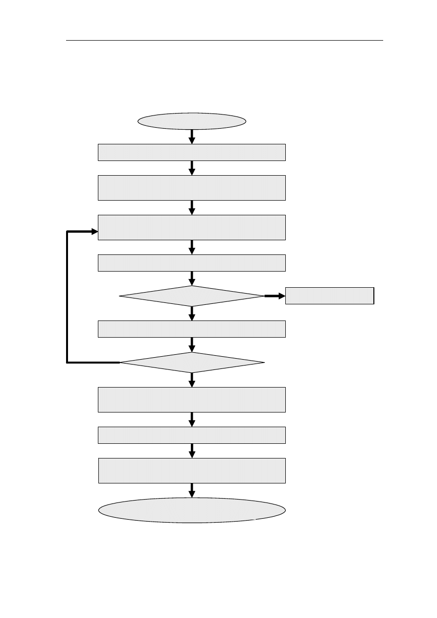
Workflow of damage scenario
General alarm: Information to all crew members (passengers)
Occurrence of damage
Closing of watertight doors and hatches as well as
weathertight closing appliances and valves in piping
Check of the extent of damage
and sounding of the compartments
Calculation of the flooding rate
Pump capacity > Flooding rate
No
Yes
Continue pumping
Calculation of the final floating position
Finished flooding
Calculation for filling/discharging of ballast water to
improve the floating position (stability & strength check)
Liquid transfer operation acc. to calculation results
Information of the present situation to
local coast guard, owner, ERS
No
Further actions in order to stabilise the vessel
based on calculation or guidance from ERS

Model Booklet for Container Vessels - Damage Control Booklet
9 of 16
4.2
Actions to be taken in case of damage
The following actions are to be taken immediately after damage in order to ensure the watertight
integrity and to assess the severity of damage.
4.2.1
Closing of watertight doors and hatches
All watertight doors and hatches are to be closed immediately!
In general the status of watertight doors and hatches is closed (refer to list of watertight openings given
above). This status can be checked on the status panel on the bridge. Additionally a visual check by a
designated person shall be performed ensuring the tightness of these doors/hatches. Prior to sending a
crew member to such an inspection route, it is to be justified that the personal risk for this person is
within acceptable limits.
In case it is deemed absolutely necessary to open a watertight door/hatch again in the damaged
condition in order to proceed with further actions, it should be carefully judged whether this door is
crucial to prevent progressive flooding. After use the door/hatch is to be closed immediately.
4.2.2
Closing of weathertight openings
All weathertight doors and hatches are to be closed immediately. Furthermore the closing appliances for
ventilation openings are to be secured.
4.2.3
Closing of valves
All vales in the piping system are to be closed immediately as far as the connected pipes are not used
for pumping operations.
4.2.4
Check of the extent of damage
If possible, a visual check of the extent of damage and the included compartments shall be carried out.
4.2.5
Sounding of flooded compartments
After having found out which compartments are damaged, the amount of inflooded water shall be
determined by sounding measurements. In case a compartment is connected to the remote sounding
system the amount of inflooded water can be determined directly.
4.2.6
Draft readings
Draft measurements at the draft marks shall be performed. Additionally the heeling angle shall be noted.
4.2.7
Calculation of inflooded water
By a periodical measurement of the sounding for damaged compartments and comparison with the draft
readings a calculation of the inflooding water per time (flooding rate) can be made.

Model Booklet for Container Vessels - Damage Control Booklet
10 of 16
4.2.8
Use of pumps
Two (2) pumps in the water ballast system and bilge system are available for pumping out water from
compartments which have been damaged.
Two scenarios may arise:
The amount of inflooding water exceeds the capacity of the available pumps. In this case the
compartment must be isolated by closing all watertight accesses (including vales in the piping
system). The use of pumps is only partly useful,
The pump capacity exceeds the rate of inflooded water therefore the pumping shall be continued
permanently.
The pumps shall be held in a permanent stand-by modus and ready for service at any time.
4.2.9
Use of Loading Computer
For determining possible scenarios of liquid transfer operations, the loading computer might be used
(refer to Chap. 5). Restrictions of the ability of the Loading Computer are to be considered.
4.2.10 Liquid transfer operations
Before any filling or discharging of water ballast is carried out a thorough check and pre-calculation of
the resulting floating position is to be carried out and the limit values for stability and longitudinal
strength are to be checked.
The crew must be aware that filling or discharging of water ballast tanks can have negative influences
on the stability due to the effect of free surfaces for partially filled tanks!
For this reason it is strongly recommended before liquid transfer operations will take place that the
possible negative effects of such operations are assessed by pre-calculation (e.g. by land based
consultancies).
In order to minimise the heel and trim of the vessel it may be advisable that water should be pumped in
the tanks opposite to the damage location. If possible, the filling of slack tanks should be preferred to
improve the stability behaviour of the vessel.
4.2.11 Determination of the ground condition (in case of grounding only)
In case the vessel is run aground a check of the ground condition and the extent of damage can be
performed by a diver. This check shall only be performed with the necessary safety measures when the
ship is in a stable position and no movement on the ground is anticipated.
4.2.12 Information to owner, coast guard and consultancy services
The local coast guard and the owner of the vessel shall be informed about the present situation. A
possible outflow of oil should be stated immediately.
In general all information about damage extent, floating position and loading condition prior to damage
shall be forwarded to consultancy services in order to get support in determining the severity of the
damage and to determine the necessary actions to be taken.

Model Booklet for Container Vessels - Damage Control Booklet
11 of 16
5 Use of Stability Computer
The use of a Loading Computer for an estimation of the stability after damage is very restricted as
common loading instruments are not able to calculate damage stability in a correct way. - Any
calculation which has been carried out with a normal Loading Computer intended for intact calculation
should be regarded as a very rough estimation only. Such results should be treated with utmost caution!
In case the loading instrument is capable of calculating damage stability, the exact loading condition
prior to the accident and the actual extent of damage shall be considered.
6 Summary of damage stability calculation
6.1
Applicable regulation
The vessel complies with the requirements as laid down in SOLAS II-1. This damage stability regulation
is based on a probabilistic concept which means that the probabilities of possible damages are
considered acc. to standardised formulas. The survivability of the vessel assumed damaged with these
possible damages is assessed. The combination of probability and resulting survivability leads to a
certain contribution to a attained index A which has to be greater than the required index R (A>R).
This kind of damage stability analysis is based on several assumptions (e.g. permeability of rooms,
considered initial drafts and GMs). The calculated results according to the regulations can differ
significantly from results of real damages of an actual loading condition.
6.2
Damage stability criteria
If all of the following criteria are met, a damage case gives full contribution to the attained index A:
Final heeling angel
≤ 25
deg.
Maximum value of the righting lever curve ≥ 0.12
m
Range of the righting lever curve
≥ 16
deg.
No immersion of opening points
If the floating position is more critical, a smaller contribution is considered.
6.3
Special remarks
Acc. to SOLAS II-1 no additional heeling moments (e.g. wind), no wave action and no longitudinal
strength limitations were considered in the damage stability calculation.

Model Booklet for Container Vessels - Damage Control Booklet
12 of 16
7 Sample damage cases
In the following, the floating position and the GZ-curve of the vessel as well as the critical openings are
shown for selected damage cases.
CAUTION: As below listed damage results are taken from the approved damage stability
calculation, they are based on several assumptions (e.g. permeability of rooms, considered
initial drafts and GMs). The calculated results can differ significantly from results of real
damages of an actual loading condition.
7.1
Summary of sample damage cases
Deepest subdivision draft:
d
S
= 12.50m GM = 0.40 m permeability of cargo hold = 0.70
Damage Description draft
aft
[m]
draft
fwd
[m]
heel [deg]
D01
Cargo hold 1
To be completed
To be completed
To be completed
D02
Cargo hold 2
D03
Cargo hold 3
D04
Cargo hold 4
D05
Cargo hold 5
D06
Cargo hold 6
D07 Eng.
room
Partial subdivision draft:
d
P
= 9.50 m
GM = 0.60 m permeability of cargo hold = 0.80
Damage Description draft
aft
[m]
draft
fwd
[m]
heel [deg]
D01
Cargo hold 1
To be completed
To be completed
To be completed
D02
Cargo hold 2
D03
Cargo hold 3
D04
Cargo hold 4
D05
Cargo hold 5
D06
Cargo hold 6
D07 Eng.
room
Lightest service draft:
d
L
= 5.00m
GM = 3.60 m permeability of cargo hold = 0.95
Model booklet treatment note:
The following sample cases should be shown:
• each of the three drafts acc. SOLAS
• one damage per cargo hold compartment and one damage for engine room
• full transverse and vertical penetration (e.g. damage 4.0.0*, not damage 4.1.0*), even if s=0
• if s=0 for full transverse and vertical penetration (e.g. 4.0.0*), a damage with reduced
transverse and / or vertical penetration could be shown additionally (e.g. 4.1.0*)
* Nomenclature of certain software, other nomenclature may differ

Model Booklet for Container Vessels - Damage Control Booklet
13 of 16
Damage Description draft
aft
[m]
draft
fwd
[m]
heel [deg]
D01
Cargo hold 1
To be completed
To be completed
To be completed
D02
Cargo hold 2
D03
Cargo hold 3
D04
Cargo hold 4
D05
Cargo hold 5
D06
Cargo hold 6
D07 Eng.
room
Model Booklet for Container Vessels - Damage Control Booklet
14 of 16
7.2
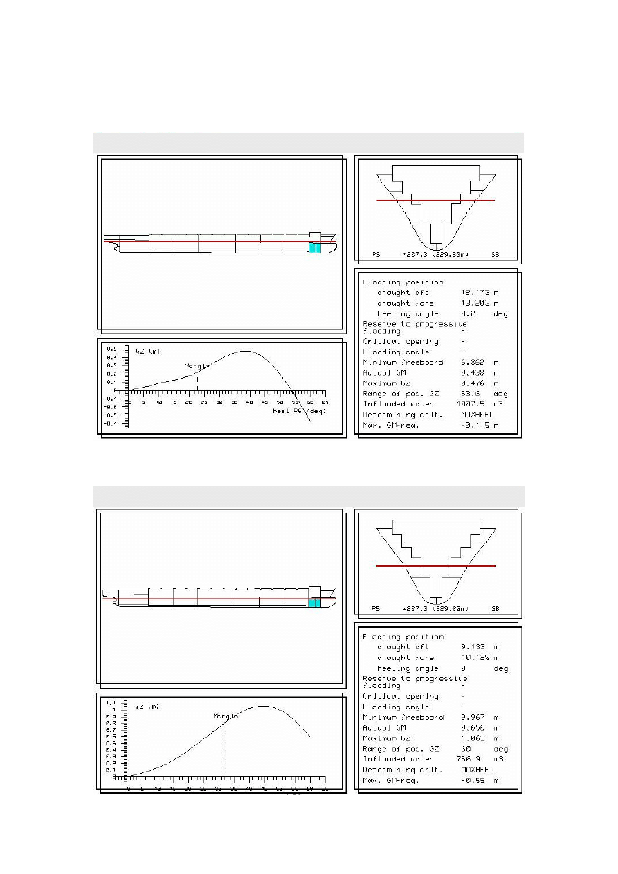
Details of sample damage cases
Damage of cargo hold 1
Deepest subdivision draft (d
S
= 12.50m, GM = 0.40 m)
Partial subdivision draft (d
P
= 9.50 m, GM = 0.60 m)
Model Booklet for Container Vessels - Damage Control Booklet
15 of 16
Lightest subdivision draft (d
L
= 5.00 m, GM = 3.60 m)
To be completed
.
.
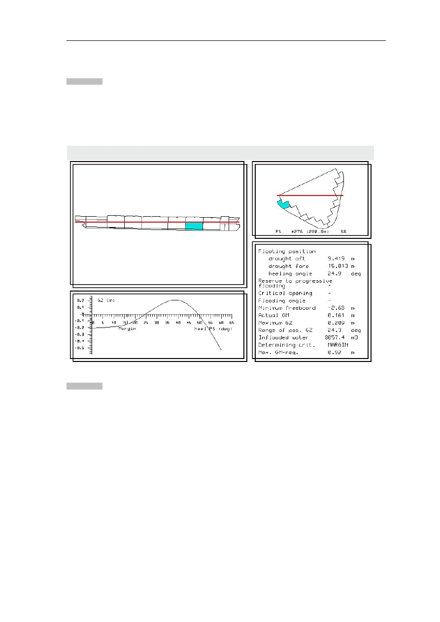
Damage of Cargo Hold No. 3
Full draft (d
max
= 12.50 m, GM = 0.40 m)
To be completed

Model Booklet for Container Vessels - Damage Control Booklet
16 of 16
8 Annex
8.1
Damage Control Plan
8.2
General Arrangement Plan
8.3
Diagram of BW-system
8.4
Diagram of bilge/scupper system
8.5
Diagram of heeling system
8.6
Diagram of air- and sounding pipes
8.7
Diagrams of fuel oil filling, transfer and overflow system
Model booklet treatment note:
The customer should adjust the list of drawings included to the arrangement of the particular vessel.
In certain cases, further additional drawings may be required to show the damage control related
arrangement of the vessel.
Wyszukiwarka
Podobne podstrony:
Damage Control Plan
CONTROLLING JAKO METODA ZARZADZ Nieznany
04 Wykonywanie podstawowych for Nieznany (2)
controlling (9 stron) id 119256 Nieznany
epigenetic control of plant dev Nieznany
Damage control plan ORLA
06 Control of respiratory funct Nieznany
Ancient Skeletal Evidence for L Nieznany (2)
DAMAGE CONTROL PLAN
Controlling bankowy 2 id 119273 Nieznany
praca (szukanie pracy, cv, ofer Nieznany
pesze, AM SZCZECIN, INSPEKCJE MORSKIE, DAMAGE CONTROL PLAN
Damage Control Plan 1 3
ControlLogix L7x id 119373 Nieznany
Damage Control Plan
CONTROLLING JAKO METODA ZARZADZ Nieznany
więcej podobnych podstron