Instruction for part program generating
using KSPT/KSPF package
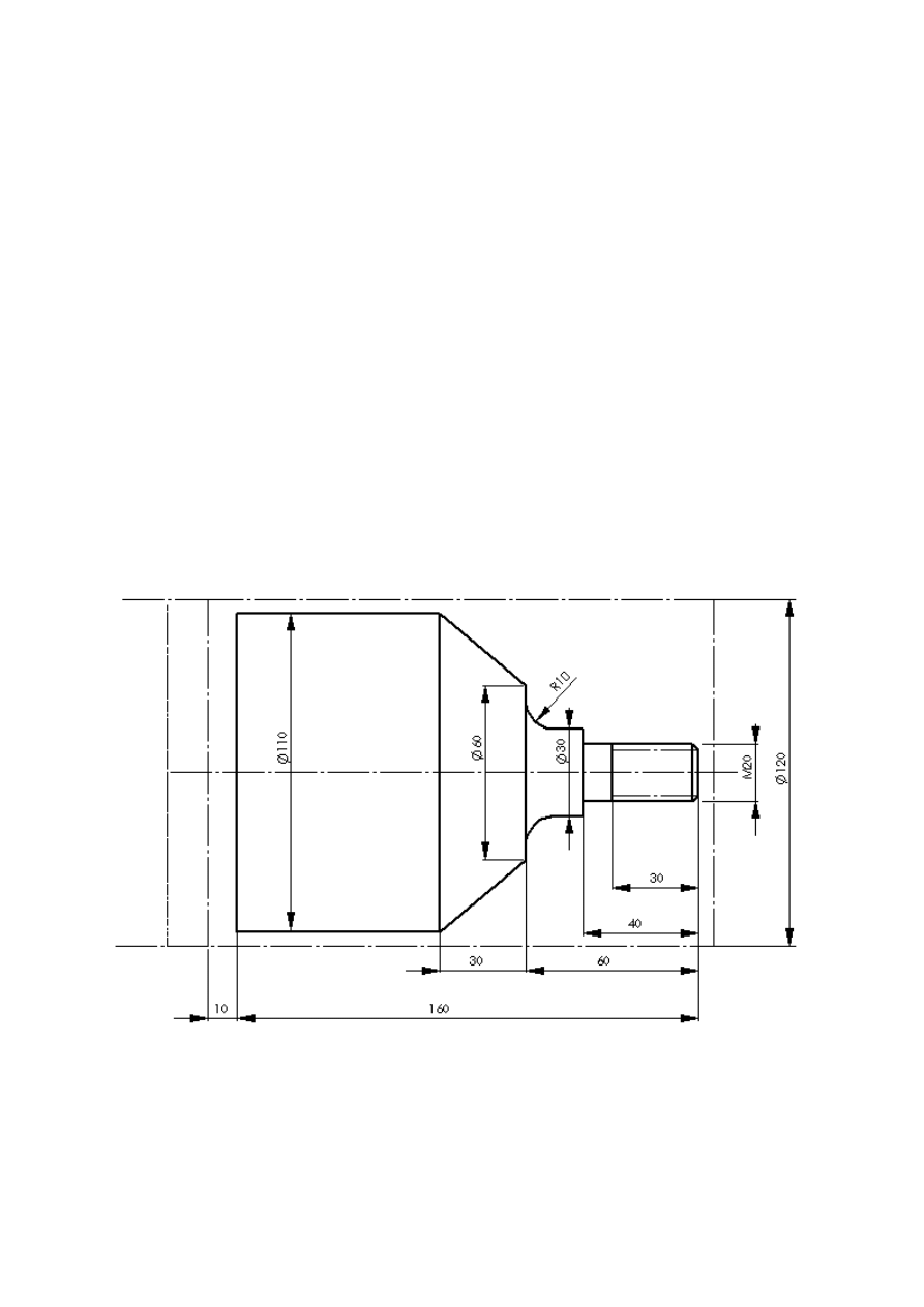
1. Description of geometry
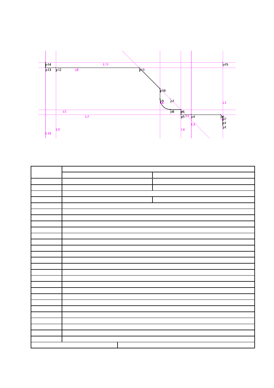
1.1. Geometrical elements
Element
Positions of geometrical elements (coordinates or definition method)
number
X [mm]
Z [mm]
P1
0
0
P2
8
0
L1
Line through P1 and P2 points
P3
10
-2
L2
Horizontal line through P3 point
L3
Vertical line Z=-30
P4
Intersection point of L2 and L3 lines
L4
Vertical line Z=-40
L5
Horizontal line X=15
P5
Intersection point of L2 and L4 lines
P6
Intersection point of L4 and L5 lines
L6
Vertical line Z=-60
L7
Line at the angle of 45
o
to horizontal direction
P7
Point on L7 line with coordinate Z=-50
C1
Circle with centre in P7 point and radius R=10
P8
Intersection point of C1 circle and L5 line
P9
Intersection point of C1 circle and L6 line
P10
Intersection point of L6 and L7 lines
L8
Horizontal line X=55
P11
Intersection point of L7 and L8 lines
L9
Vertical line Z=-160
P12
Intersection point of L8 and L9 lines
L10
Vertical line Z=-170
P13
Intersection point of L8 and L10 lines
L11
Horizontal line X=60
P14
Intersection point of L10 and L11 lines
P15
Intersection point of L1 and L11 lines
Base point coordinates
X = 80, Z = 20

1.2. Description of contours
1.2.1. Contour for finishing – O1
Geometry/Contour/1.Define
Input No:1, click on the arrow and choose Point No.
Repeat operation for points: P2, P3, P5, P6, P8, P9, P10, P11, P13, P14
Allowance D=1 (to use in roughing contour O11)
Finish contour definition by pressing END button.
1.2.2. Contour for roughing – O11
Geometry/Contour/B.Allowance contour
Nr:11, O:1, Str:-1 (allowance contour will be placed upper and on right)
1.3. Base point coordinates
Edit, write BAS/ZS20,XS80
2. Technology
2.1. Tools definition
2.1.1. Facing and Roughing
Technology/Tools/Definition
Choose the right cutter (roughing/finishing cutter - form cutter - grooving cutter - drill)
-
Tool No: 1,
-
Identifiers of - tool1: 71.26 RA 3225,
-
Insert: TNMG 2204,
-
Holder: - ,
-
Insert material: S10,
-
Total length: 150,
-
Width * Height: 3225,
-
Z: -36,
-
X: -150,
-
R: 0.8,
-
Characteristic Point No: 0,
-
Tool cutting edge angle: 93,
-
Auxiliary tool cutting edge angle: 27.
2.1.2. Finishing
Technology/Tools/Definition
Choose the right cutter (roughing/finishing cutter - form cutter - grooving cutter - drill)
-
Tool No: 2,

-
Identifiers of - tool1: NNWd 3225
-
Insert: -,
-
Holder: - ,
-
Insert material: S10,
-
Total length: 150,
-
Width * Height: 3225,
-
Z: -30,
-
X: -150,
-
R: 0.1,
-
Characteristic Point No: 0,
-
Tool cutting edge angle: 100,
-
Auxiliary tool cutting edge angle: 50.
2.1.3. Threading
Technology/Tools/Definition
Choose the right cutter (roughing/finishing cutter - form cutter - grooving cutter - drill)
-
Tool No: 3,
-
Identifiers of – tool: NNGr 3225,
-
Insert: -,
-
Holder: - ,
-
Insert material: S10,
-
Total length: 150,
-
Width * Height: 3225,
-
Z: -27,
-
X: -150,
-
60.
2.2. Operations – Tool path generating
2.2.1. Facing
a) Cutting parameters - Technology/Cutting parameters:
-
Feed 0.1 mm/rev
-
Rotational speed 355 rev/min
-
Coolant on
-
Direction of revolutions CCW
b) Tool calling – Technology/Tools/Calling
Click on required tool, assign tool number, position in head and corrector number.
Choose upper head and return to base.
c) Tool path in “Operation” mode – Technology/Machining/Operations
-
click dashed arrow (positioning movement), Coordinates Z=0, X=61,
-
click continuous arrow, Coordinates Z=0, X=0,
-
click dashed arrow, Coordinates Z=20, X=80.

2.2.2. Roughing
a)
Tool calling – Technology/Tools/Calling
b) Tool path in “Cycle” mode – Technology/Machining/Cycles
-
choose the “roughing” icon,
-
Ending Contour No 11,
-
Starting Contour No -- (default dimensions of workpiece),
-
Max. depth of machining 3 [mm],
-
Approach value 1,
-
Choose Feed directions and Cycle type,
-
click OK and input cutting parameters: Feed 0.3 mm/rev, Revolutions 450 rev/min.
2.2.3. Finishing
b)
Tool calling – Technology/Tools/Calling
b) Tool path in “Cycle” mode – Technology/Machining/Cycles
-
choose the “finishing” icon,
-
Contour No 1,
-
Approach value 1,
-
Retract value 1,
-
Allowance 1,
-
Engagement angle 0,
-
Disengagement angle 0,
-
Choose Type of contour,
-
click OK and input cutting parameters: Feed 0.1 mm/rev, Revolutions 560 rev/min.
2.2.4. Threading
c)
Tool calling – Technology/Tools/Calling
b) Tool path in “Cycle” mode – Technology/Machining/Cycles
-
choose the “threading” icon,
-
click metric,
-
click standard,
-
click constant pitch,
-
click external,
-
click radial feed,
-
click Constant chip section,
-
click OK and input other parameters:
-
Initial thread diameter 20
-
Starting Point No 3,
-
Ending Point No 4,
-
Approach value 1,
-
Retract value 3,
-
Move back value 1,

-
Number of passes 10,
-
click Slantwise engagement,
-
click OK and input cutting parameters: Feed 2.5 mm/rev, Revolutions 180 rev/min.
2.3. Simulation according to CLData
Save CLData file (File/Save CLD.DTA) and simulate cutting (Simulators/Simulation).
2.4. Generating part program for CNC machine tool
Choose the right postprocessor (Postprocessors/List of postprocessors) and follow the
instructions to finish the part program.
2.5. +3+
2.6.+
2.7.
Simulation according to part program – Simulators/ISO code pgm simulation
3.
Elaboration of part geometry and technology using
“Group Technology” mode
a) start polish version of KSPT/KSPF package,
b)
choose “Technologia grupowa” (Group Technology) option – Technologia/Obróbka,
Technologia grupowa,
c)
click Wałki (Shafts) and choose the most similar part,
d)
input the right dimensions according to drawing symbols,
e) generate the part program for CNC machine tool.
Document Outline
Wyszukiwarka
Podobne podstrony:
Instrukcje do ćwiczeń 2013
LAB 2 Instrukcja wykonania cwiczenia
INSTRUKCJA 01 01 2013 ŻYW
Instructions for?sicLog
instructions for zen meditation 2GVX7YJXPQNLC74CRS3FJNXUAOIXYARA5IRHJXY
petle, Instrukcja for
LAB instrukcje, Ćwiczenie 13, Przebieg _wiczenia:
Analiza FOR 11 2013 Iluzja konsultacji społecznych i reformy systemu emerytalnego
Lab 1 Instrukcja wykonania cwiczenia Stal weglowa i stopowa
MB (Lab) Instrukcja nr 06
MB (Lab), Instrukcja nr 06
LAB instrukcje, Ćwiczenie 76, Ćwiczenie 76
LAB instrukcje, Ćwiczenie 15, Ćwiczenie 15
Concrete composition lab instruction
MB (Lab) Instrukcja nr 07
JS 10 Instrukcja for, Programowanie, instrukcje - teoria
więcej podobnych podstron