
CWB-4/2009
167
Dr inż. Izabela Hager
Politechnika Krakowska, Katedra Technologii Materiałów Budowlanych i Ochrony Budowli
Metody oceny stanu betonu w konstrukcji po pożarze
Methods for assessing the state of concrete in fi re damaged
structures
1. Introduction
Concrete is a construction material preserving relatively well its
properties at high temperatures. Owing to its fairly low coeffi cient
of thermal conductivity, heat movement through concrete is slow,
and thus reinforcing steel, which is sensitive to high temperature,
is protected for a long period of time. Concretes that exhibit ex-
plosive behaviour (so-called spalling) when heated rapidly are an
exception to this rule. Spalling is observed in concrete elements
heated to the temperature of 190°C–350°C, and manifests itself
by the violent delamination of concrete or its intensive fl aking (the
so-called popcorn effect), which leads to the reinforcement exposi-
tion and, as a consequence, to a sudden drop in the load-bearing
capacity of a reinforced concrete element. High-performance
concretes (HPCs) are particularly prone to explosive behaviour;
the incorporation of polypropylene fi bres (1) is an effective method
in mitigating of this phenomenon.
When concrete is heated under fi re conditions, the increase of tem-
perature of deeper layers of material is progressive, but because
this process is slow, signifi cant temperature gradients are produced
between the surface and the core of the concrete member (2). As
a result of concrete being exposed to heat and as a consequence
of temperature gradients formed, degradation occurs, which is most
frequently measured by determining changes in the compressive
strength of concrete. Research has demonstrated that changes in
the strength of concrete as a function of temperature are related
to, inter alia, concrete composition (the type of aggregate, the
1. Wprowadzenie
Beton jest materiałem konstrukcyjnym zachowującym stosunkowo
dobrze swoje właściwości w podwyższonych temperaturach. Dzięki
stosunkowo niskiemu współczynnikowi przewodności cieplnej,
ruch ciepła w tym materiale jest powolny, co długo chroni wrażli-
wą na działanie temperatury stal zbrojeniową. Wyjątek stanowią
betony wykazujące po ich gwałtownym ogrzaniu skłonność do
eksplozyjnego zachowania się (tzw. spalling). Zjawisko „spallingu”
występuje w elementach betonowych ogrzanych do temperatury
w zakresie 190°C – 350°C i objawia się gwałtownym odspajaniem
się fragmentów betonu lub jego intensywnym złuszczaniem (tzw.
efekt pop-cornu), co prowadzi do odsłonięcia zbrojenia, a w kon-
sekwencji do gwałtownej utraty nośności elementu żelbetowego.
Betonami wykazującymi skłonność do eksplozyjnego zachowania
się są zwłaszcza betony wysokowartościowe (HPC), a skuteczną
metodą przeciwdziałania temu zjawisku jest stosowanie włókien
polipropylenowych (1).
W trakcie ogrzewania betonu w warunkach pożarowych wzrost
temperatury głębszych partii materiału następuje stopniowo, jednak
na skutek powolnego przebiegu tego procesu, w elemencie beto-
nowym powstają duże różnice temperatur pomiędzy powierzchnią
elementu i jego wnętrzem (2). Efektem działania temperatury na
beton oraz wystąpienia gradientów temperatury jest jego degra-
dacja, którą najczęściej określa się poprzez przedstawienie zmian
wytrzymałość na ściskanie. Jak pokazują badania zmiany wytrzy-
małości w funkcji temperatury związane są między innymi ze skła-
MIĘDZYNARODOWE CZASOPISMO NAUKOWE
POŚWIĘCONE ZAGADNIENIOM CHEMII
I TECHNOLOGII MATERIAŁÓW WIĄŻĄCYCH I BETONU
ROK XIII/LXXV
LIPIEC – SIERPIEŃ 2009 r.
Nr 4
Organ Stowarzyszenia Producentów Cementu

168
CWB-4/2009
dem betonu (rodzaj zastosowanego kruszywa, wskaźnik wodno-
spoiwowy, obecność dodatków pucolanowych, itp.), jednak przede
wszystkim zależą od szybkości wzrostu temperatury oraz od czasu
jej oddziaływania na beton (3, 4). Stopniowa degradacja betonu
jest wynikiem zachodzących w nim przemian fi zykochemicznych.
Wzrost temperatury powoduje odparowanie wody z materiału,
rozkład żelu CSH, wodorotlenku wapniowego i glinianów wapnio-
wych. Równocześnie ze wzrostem temperatury zachodzą także
przemiany w kruszywie, między innymi w temperaturze 573°C
ma miejsce przemiana fazowa kwarcu, której towarzyszy wzrost
objętości, a w temperaturze 800°C dochodzi do rozkładu kruszyw
wapiennych. Konsekwencją tych zjawisk jest zmiana właściwości
fi zycznych betonu, a przede wszystkim jego wytrzymałości (3, 4).
Przyjąć można, że wytrzymałość betonu stopniowo maleje wraz ze
wzrostem temperatury, a po przekroczeniu ok. 300°C spadek ten
następuje szybciej. Przekroczenie temperatury 500°C powoduje
zazwyczaj spadek wytrzymałości na ściskanie o 50-60%, a beton
uznaje się za zniszczony (6). Na tym założeniu opiera się metoda
obliczania nośności elementu żelbetowego po pożarze według
założeń Eurokodu (7). W metodzie „izotermy 500°C” pomija się
w obliczeniach części powierzchni betonu, w której temperatura
przekroczyła 500°C.
Metody diagnostyczne mają na celu nie tylko ocenę stopnia de-
gradacji materiału spowodowaną działaniem wysokiej temperatury,
ale również ocenę zasięgu zaistniałych zmian. Zasięg degradacji
betonu jest ściśle powiązany z przebiegiem izoterm w ogrzewanym
materiale. Jak już wspomniano uszkodzenia betonu spowodowane
działaniem temperatury opisuje się najczęściej przez określenie
resztkowej wytrzymałości na ściskanie lub/i modułu sprężystości
metodami niszczącymi, bądź nieniszczącymi. Jednak zmianom
spowodowanym działaniem temperatury ulegają również inne
właściwości fi zyczne betonu: jego gęstość, porowatość (całkowita
ilość porów i średnia wielkość porów), kolor, twardość, itp. Zmiana
tych cech stanowi podstawę innych metod oceny stanu betonu
po pożarze.
Przeprowadzone badania stanu betonu w konstrukcji po pożarze,
pozwalające na określenie jego resztkowych właściwości mecha-
nicznych oraz głębokości występowania uszkodzeń, umożliwiają
podjęcie decyzji o zakresie działań naprawczych lub prac wzmac-
niających element betonowy.
2. Metody oceny stanu betonu w konstrukcji po
pożarze
Ocenę uszkodzeń pożarowych betonu w konstrukcji zazwyczaj
rozpoczyna ocena wizualna, oparta na obserwacji zmian spowodo-
wanych wpływem temperatury. W celu uproszczenia tego zadania
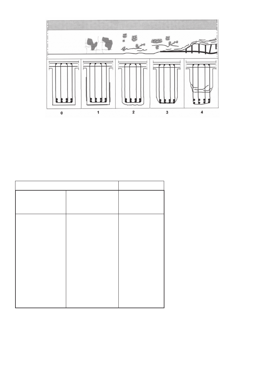
stworzono czterostopniową klasyfi kację uszkodzeń dla belek (ry-
sunek 1), słupów i płyt (5, 8), wraz z przewidywanymi metodami
naprawczymi dla każdej z klas. Stan elementu ocenia się biorąc
pod uwagę następujące parametry: obecność sadzy i osmolenia,
zmianę koloru betonu, wystąpienie złuszczeń betonu lub odspojeń,
obecność rys i mikrorys, stopień odsłonięcia stali zbrojeniowej oraz
water/cement ratio, the presence of pozzolana additives, etc.),
but they are basically determined by the rate of heating and the
time of concrete exposition to the temperature (3, 4). The gradual
degradation of concrete is the result of physico-chemical changes.
The increase of temperature results in water evaporation, the CSH
gel, calcium hydroxide and calcium aluminates decomposition,
etc. In parallel with the increase of temperature the changes in the
aggregate take place, among other the polymorphic transformation
of quartz occurs at the temperature of 573°C which is accompa-
nied by an increase in its volume; at 800°C, limestone aggregates
decompose. As a consequence of these phenomena, the physical
properties of concrete change (3, 4), in particular compressive
strength. It can be assumed that concrete strength decreases
gradually as the temperature increases, and when the temperature
exceeds ca. 300°C, the decline in strength becomes more rapid.
When the 500°C threshold is passed, the compressive strength of
concrete usually drops by 50 to 60%, and the concrete is consi-
dered fully-damaged (6). The Eurocode method of calculating the
load-bearing capacity of reinforced concrete elements subjected
to a fi re is based on this assumption (7). In the 500°C isotherm
method, sections of concrete surface where the temperature had
exceeded 500°C are disregarded in calculations.
Diagnostic methods aim not just to assess the degree of material
degradation caused by exposure to high temperatures, but also
to determine the extent of the changes caused. The extent of
concrete degradation is closely correlated with the distribution of
isotherms in the heated material. As has already been mentioned,
concrete damage caused by temperature is usually measured by
determining residual compressive strength and/or the modulus of
elasticity using destructive or non-destructive methods. However,
other physical properties of concrete are also subject to change as
a result of exposure to heat: its density, porosity (the total number
and average size of pores), colour, hardness, etc. are affected.
Changes in these features form the basis for other methods of
assessing the condition of fi re-damaged concrete.
Assessment of the condition of concrete structures after being
exposed to fi re, permit the determination of its residual mecha-
nical properties as well as the depth of the damage and make it
possible to decide on remedial action or steps aimed at reparation
and reinforcing the concrete element in question.
2. Methods of assessing the condition of
concrete in structures after fi re
The assessment of fi re damage of concrete structure usually
starts with a visual evaluation, which consists in establishing the
changes caused by heat exposure. In order to simplify this task,
a four-degree classifi cation of damage of beams (Fig. 1), columns
and slabs (5, 8) has been developed, which includes the usual
repair methods for each damage class. The condition of element
is classifi ed through the assessment of the following parameters:
the presence of soot and smoke deposits, the colour change of
concrete, concrete fl aking or spalling, the presence of cracks and
CWB-4/2009
169
ewentualnie widoczne odkształcenia elementu konstrukcyjnego
(nadmierne ugięcie belek, lub wyboczenie słupów).
W tablicy 1 zestawiono stosowane metody mające na celu bardziej
precyzyjną ocenę uszkodzeń betonu w konstrukcji. Techniki diag-
nostyczne podzielono na dwie główne grupy: badania wykonywane
microcracks, the degree to which reinforcing
steel is exposed and possible visible deforma-
tions of the structure (excessive defl ection of
beams and lateral distortion of columns).
In Table 1 the methods used to assess dama-
ge of concrete structures in a more precise
manner are depicted. Diagnostic techniques
fall into two main groups: in situ and laboratory
tests. Moreover, three groups of tests have
been distinguished. Group I comprises test
methods where the condition of a concrete
element is assessed at a single point. Group
II embraces special techniques enabling the
overall response assessment of the concrete
element. Finally, Group III includes assess-
ment techniques based on the properties exa-
mination of small samples taken from various
locations and at different depths.
2.1. In situ methods
Most of the in situ techniques included in
Group I that are used to assess the condition
of concrete after being exposed to fi re are well-
known methods that are widely used to check
the properties of concrete structures.
The sclerometric test is one of the most commonly used methods
for estimating the hardness of the surface concrete layer. The
limitations of this technique in diagnosing fi re damage of concrete
result from the absence of a fi xed correlation between compressive
Rys. 1. Klasyfi kacja uszkodzeń pożarowych belki według (5, 8), 0 – beton nieuszkodzony termicznie, 1 – obecność sadzy i osmolenia, widoczna sieć
mikrozarysowań, 2 – odpryski powierzchniowe wielkości do10 mm, rysy widoczne i zorientowane (rozwartość > 0,5 mm), 3 – widoczne ubytki otuliny
zbrojenia, beton złuszczony, widoczne odsłonięte zbrojenie, 4 – zbrojenie widoczne i uszkodzone, wyraźne ubytki znacznej części betonu
Fig. 1. Classifi cation of fi re damage of the beams according to (5, 8): 0 – no thermal damage of concrete; 1 – soot and smoke deposits present, a ne-
twork of microcracks visible; 2 – surface spalling (to 10 mm in diameter), visible oriented cracks (crack width > 0.5 mm); 3 – visible damage of concrete
cladding, spalling of concrete, exposed reinforcement visible; 4 – reinforcement visible and damaged, signifi cant loss of concrete.
Table 1
ASSESSMENT METHODS OF FIRE-DAMAGED CONCRETE IN STRUCTURES
In situ methods
Laboratory methods
Group I. Local assessment
of concrete condition
Group II. Special methods for
the overall assessment of the
condition of concrete within
element
Group III. Assessment
of concrete properties
based on core drilling
Non-destructive methods:
– visual evaluation;
– sclerometric assessment;
– ultrasound assessment.
Partially destructive
methods:
– “pull-off” tests;
– “pull-out” (CAPO) test;
– Windsor probe;
– BRE internal fracture test;
– drilling resistance.
Multichannel Analysis of Surface
Waves (MASW) method
Ground Penetrating Radar
(GPR)
Analysis of surface images of
damaged concrete
Assessment of mechanical
properties of core:
– direct method;
– indirect methods (reso-
nance frequency test,
ultrasound method)
Estimating the temperature
reached by concrete:
– colourimetry;
– DTA and TGA;
– X-ray diffraction;
– scanning microscopy;
– thermoluminescence;
– porosimetry;
– microcrack density
assessment.

170
CWB-4/2009
in situ oraz badania laboratoryjne.
Ponadto wyróżniono trzy grupy
badań. Grupę I stanowią metody
badań, w których punktowej oce-
nie podlega beton w elemencie
betonowym. Do grupy II zalicza
się specjalne techniki komplekso-
wej oceny elementu betonowego.
Grupa III obejmuje metody oceny
oparte na badaniu właściwości
odwiertów pobranych w różnych
punktach i z różnej głębokości
elementu betonowego.
2.1. Metody stosowane in
situ
Większość technik stosowanych
in situ do oceny stanu beto-
nu po pożarze, które znalazły
się w grupie I, to metody zna-
ne i powszechnie stosowane
do kontroli właściwości betonu
w konstrukcji.
Metoda sklerometryczna stanowi
jedną z najczęściej stosowanych
metod orientacyjnej oceny twardości powierzchniowej warstwy
betonu. Ograniczenia tej techniki w diagnostyce pożarowych
uszkodzeń betonu wynikają z braku stałej zależności między
wytrzymałością na ściskanie, a liczbą odbicia stanowiąca wynik
pomiaru sklerometrem. Ponadto, warunkiem uzyskania prawidło-
wych wyników jest wykonywanie pomiarów na płaskiej powierzchni,
co w przypadku elementu silnie uszkodzonego działaniem pożaru
ze znacznymi złuszczeniami i odspojeniami jest trudne do zrealizo-
wania. Wykonywanie badania sklerometrem zakłada następujące
etapy: weryfi kację prawidłowości funkcjonowania urządzenia,
ustalenie liczby odbicia w strefi e betonu nienaruszonego oraz
wykonanie pomiarów w strefach uszkodzeń, według założonego
schematu rozmieszczenia pomiarów. Zaproponowany przez Labo-
ratorium Dróg i Mostów w Paryżu (8) schemat przyjęty do oceny
betonowych elementów sklepienia tunelu pod kanałem La Man-
che zakłada promieniste rozmieszczenie punktów pomiarowych,
w równomiernych odległościach od strefy wyraźnych uszkodzeń.
Zazwyczaj pomiarom sklerometrycznym towarzyszy pomiar wy-
trzymałości na ściskanie badany na odwiertach w celu znalezienia
korelacji liczby odbicia z wytrzymałością na ściskanie.
W grupie technik nieniszczących obok metody sklerometrycznej
stosuje się technikę opartą na pomiarze prędkości rozchodzenia
się fali ultradźwiękowej. Prędkość rozchodzenia się fali ultra-
dźwiękowej w betonie jest związana z jego modułem sprężystości
oraz z wytrzymałością na ściskanie. Dzięki temu możliwa jest
obserwacja wyraźnych zmian prędkości rozchodzenia się fali
ultradźwiękowej w betonie, który poddany był działaniu podwyż-
szonej temperatury (6, 8, 10). Stosując powierzchniowy układ sond
strength and the rebound index obtained as a result of sclerometric
measurements. Moreover, in order to obtain correct results, the
test should be conducted on a fl at surfaces, which is diffi cult for
concrete elements that have been heavily-damaged by fi re and
exhibit visible spalling. Sclerometer measurement method com-
prises the following stages: verifying whether the device functions
properly, establishing the rebound index for the damage-free zone
of the concrete and the performance of measurements in dama-
ge zones according to the predetermined measurement location
pattern. The pattern proposed by Laboratoire Central des Ponts et
Chaussées in (8) for testing the fi re damaged concrete in the lining
of the Channel Tunnel assumes a radial pattern of measurement
points, which are equidistant from the visible damage zone. Scle-
rometric measurements are usually accompanied by compressive
strength measurements of cores in order to correlate the rebound
index with compressive strength.
In the group of non-destructive methods another technique, ba-
sed on the measurement of the ultrasonic wave speed velocity, is
used. The velocity of propagation of ultrasonic wave in concrete
is related to its modulus of elasticity and compressive strength. It
is therefore possible to observe signifi cant changes in the speed
of propagation of ultrasonic waves in concrete that was exposed
to high temperature (6, 8, 10). By placing measurement probes on
the surface and increasing the distance between the source and
the receiver, it is possible to assess the properties of increasingly
deeper layers of concrete (Fig. 2). Just as for the sclerometric
method, this test requires a fl at surfaces that have not been da-
maged by spalling.
Tablica 1
METODY OCENY USZKODZEŃ POŻAROWYCH BETONU W KONSTRUKCJI
Metody in situ
Metody laboratoryjne
Grupa I. Lokalna ocena jakości
betonu
Grupa II. Specjalne metody
globalnej oceny stanu betonu
w elemencie
Grupa III. Ocena właściwości
betonu prowadzona na odwier-
tach
Metody nieniszczące:
– ocena wizualna,
– sklerometryczna,
– ultradźwiękowa.
Metody częściowo niszczące:
– metody pull-off,
– metoda pull-out (CAPO),
– sonda Windsor,
– metoda destrukcji, wewnętrz-
nej (BRE),
– opór wiercenia.
Metoda analizy fal powierzchnio-
wych (MASW)
Georadar (GPR)
Analiza obrazu uszkodzonej po-
wierzchni betonu
Ocena cech mechanicznych
odwiertów:
– metodą bezpośrednią,
– metodami pośrednimi: (me-
todą częstotliwości rezonan-
sowej, metodą ultradźwięko-
wą).
Oszacowanie osiągniętej przez
beton temperatury:
– kolorymetria,
– DTA i TGA,
– rentgenografi a,
– mikroskopia skaningowa,
– termoluminescencja,
– porozymetria,
– ocena gęstości mikro-
zarysowań.
CWB-4/2009
171
pomiarowych o zwiększającej się odległości pomiędzy nadajnikiem
i odbiornikiem można ocenić jakość coraz głębszych warstw ma-
teriału (rysunek 2). Podobnie jak w metodzie sklerometrycznej
wskazane jest prowadzenie badań ultradźwiękowych na płaskich
powierzchniach betonu, nieuszkodzonych przez odspojenia.
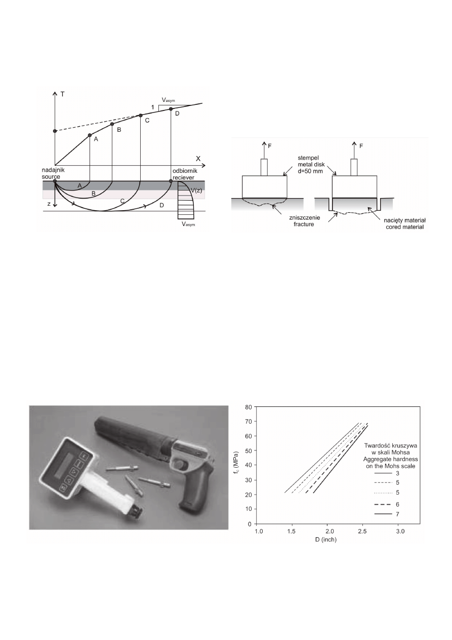
Rys. 2. Zasada pomiaru prędkości rozchodzenia się fali ultradźwiękowej.
Układ powierzchniowy sond pomiarowych umożliwiający ocenę stanu
betonu w coraz głębszych jego warstwach (10)
Fig. 2. Measurement of the ultrasonic pulse velocity. Surface arrangement
of measurement probes enabling the investigation of increasingly deeper
layers of concrete (10)
Do oceny betonu w warstwie powierzchniowej można wykorzystać
również metody częściowo niszczące. Należy do nich metoda „pull-
off”, polegająca na przyłożeniu obciążenia rozciągającego beton
poprzez metalowy stempel przyklejony żywicą epoksydową do jego
powierzchni. Położenie materiału poddawanego rozciąganiu może
znajdować się nieco głębiej w betonie, dokąd sięgać będzie nacię-
cie wykonane za pomocą piły koronkowej (rysunek 3). Technika
„pull-off” pozwala na wyznaczenie wytrzymałości na rozciąganie
betonu. W celu oszacowania wytrzymałości na ściskanie na pod-
Concrete condition within the surface layer may also be assessed
using partially destructive methods. Among these methods, the
“pull-off” test should be mentioned, consisting of applying a tensile
load to concrete via a metal disk glued to its surface with epoxy
resin adhesive. The tested material can be located deeper through
the kerf obtained with the saw (Fig. 3). The “pull-off” technique
permits the testing of the tensile strength of concrete. In order
to estimate the compressive strength on the basis of the tensile
strength determined during the “pull-off” test, appropriate experi-
mental relationships are used.
Rys. 3. Pomiar wytrzymałości na rozciąganie betonu metodą „pull-off”
Fig. 3. Tensile strength testing of concrete using the “pull-off” method
Another good method of testing the extent of damage of concrete
is the Windsor probe method, which is based on measuring the
depth to which a probe shoot from a specially constructed gun
penetrates into the concrete (Fig. 4). The strength of concrete is
found from the correlation linking the length of the probe sticking
out of the material (D, in inches) with strength. This method may
be used for ordinary and high-performance concretes (silver probe)
as well as to lightweight ones (gold probe). It is recommended that
the hardness of the aggregate used in concrete will be determined
before the test, using the 10-point Mohs scale. Subsequently, three
probes are shoot from the distance determined by the template
that is included in the kit. The average result of three values is
Rys. 4. Zestaw do pomiaru wytrzymałości na ściskanie metodą sondy Windsor oraz krzywe przedstawiające zależność między długością wystającej
części sondy (D) i wytrzymałością na ściskanie betonów z kruszyw o twardości od 3 do 7 w skali Mohsa (12)
Fig. 4. A Windsor probe compressive strength measurement kit and curves illustrating relationships between the length of probe sticking out from the
material (D) and the compressive strength of concretes made from aggregates with a hardness of 3 to 7 in the Mohs scale (12)
172
CWB-4/2009
stawie zmierzonej w próbie „pull off” wytrzymałości na rozciąganie
stosuje się odpowiednie zależności doświadczalne.
Trafną ocenę uszkodzeń betonu można uzyskać stosując metodę
sondy Windsor, opierającą się na pomiarze głębokości penetracji
sworznia wystrzelonego ze specjalnie skonstruowanego pistoletu
na naboje prochowe (rysunek 4). Wytrzymałość betonu wyznacza
się ze znalezionej korelacji łączącej długość wystającej z materiału
części sondy (D w calach), z wytrzymałością betonu na ściskanie.
Metoda ta może być stosowana zarówno do betonów zwykłych
i wysoko wartościowych (sworzeń „srebrny”), jak i do betonów
lekkich (sworzeń „złoty”). Zaleca się, aby przed rozpoczęciem
badań przeprowadzić ocenę twardości kruszywa zastosowanego
w betonie, stosując skalę Mohsa. Następnie wykonuje się trzy
strzały w odległości podyktowanej wielkością szablonu stanowią-
cego wyposażenie zestawu. Średnia z trzech pomiarów długości
wystającej części sworznia pozwala na określenie wytrzymałości
na ściskanie betonu w danym punkcie pomiarowym. Zaletą tej
techniki jest możliwość oceny wytrzymałości betonu także na
nierównej powierzchni uszkodzonej odspojeniami (6).
W krajach skandynawskich, a także w USA i Wielkiej Brytanii, sto-
sowana jest metoda „pull-out” nazywana CAPO (ang. cut and pull
out ) (6, 13). Jest to odmiana tradycyjnej techniki „pull-out” (LOK
test), w której pierścienie osadza się w betonie w trakcie betono-
wania. Specyfi ką i zaletą metody CAPO jest stosowanie pierścieni
samo-rozprężających się po wprowadzeniu do wyżłobienia, wyci-
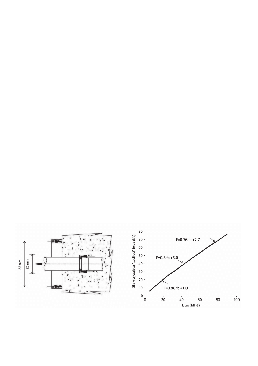
nanego frezem wewnątrz odwiertu. Metoda polega na pomiarze
siły potrzebnej do wyrwania z betonu stalowej kotwy wprowadzonej
do wykonanego w betonie kanału. Obciążenie jest przekazywane
za pośrednictwem siłownika hydraulicznego, który z jednej strony
poddaje trzpień kotwy działaniu siły wyrywającej, z drugiej zaś
jest wsparty na powierzchni betonu za pośrednictwem centrycz-
nego pierścienia oporowego (rysunek 5). Pierścień ten, dzięki
właściwemu doborowi proporcji swoich wymiarów w stosunku do
głębokości położenia kotwy oraz jej wymiarów, wymusza złożony
used to determine the compressive strength of the concrete at the
measurement point in question. The advantage of this technique is
that it enables concrete strength to be determined also on uneven
surfaces that have been damaged by spalling (6).
A method used in Scandinavia as well as in the U S and UK is the
CAPO (cut and pull out) test, which belongs to the “pull-out” group
(6, 13). This is a variant of the traditional “pull-out” technique (LOK
test), where rings are embedded in concrete during casting. An
advantage and peculiar feature of the CAPO test is the use of an
expanding ring placed in a groove cut within a drilled hole using
a milling cutter. The technique is based on the measurement of
the force required to pull out a steel anchor installed in a concrete
hole. The load is applied via a hydraulic actuator, which applies
“pull-out” force to the anchor, while on the other hand it presses the
concrete surface via a concentric stopper ring (Fig. 5). Owing to
the fact that the stopper ring dimensions are adjusted to the depth
at which the anchor is placed and to the dimensions of the anchor
itself, this arrangement results in a complex state of stress leading
to failure. On the basis of experimental relationships (Fig. 5), the
compressive strength of the concrete is estimated.
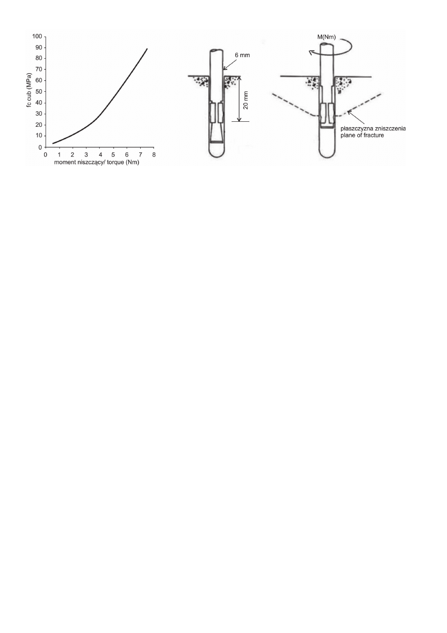
The BRE internal fracture test was developed and published by
the Building Research Establishment (14). In this method, a hole
with a diameter of 6 mm and a depth of 30 to 35 mm is drilled
in the material to be examined. An anchor with an expansion
sleeve is inserted into the hole to the depth of 20 mm. The head is
tightened using a torque wrench until the load causes the anchor
to be pulled out (Fig. 6). The direct measure of concrete quality
is the breaking moment, which is subsequently converted into
a compressive strength value.
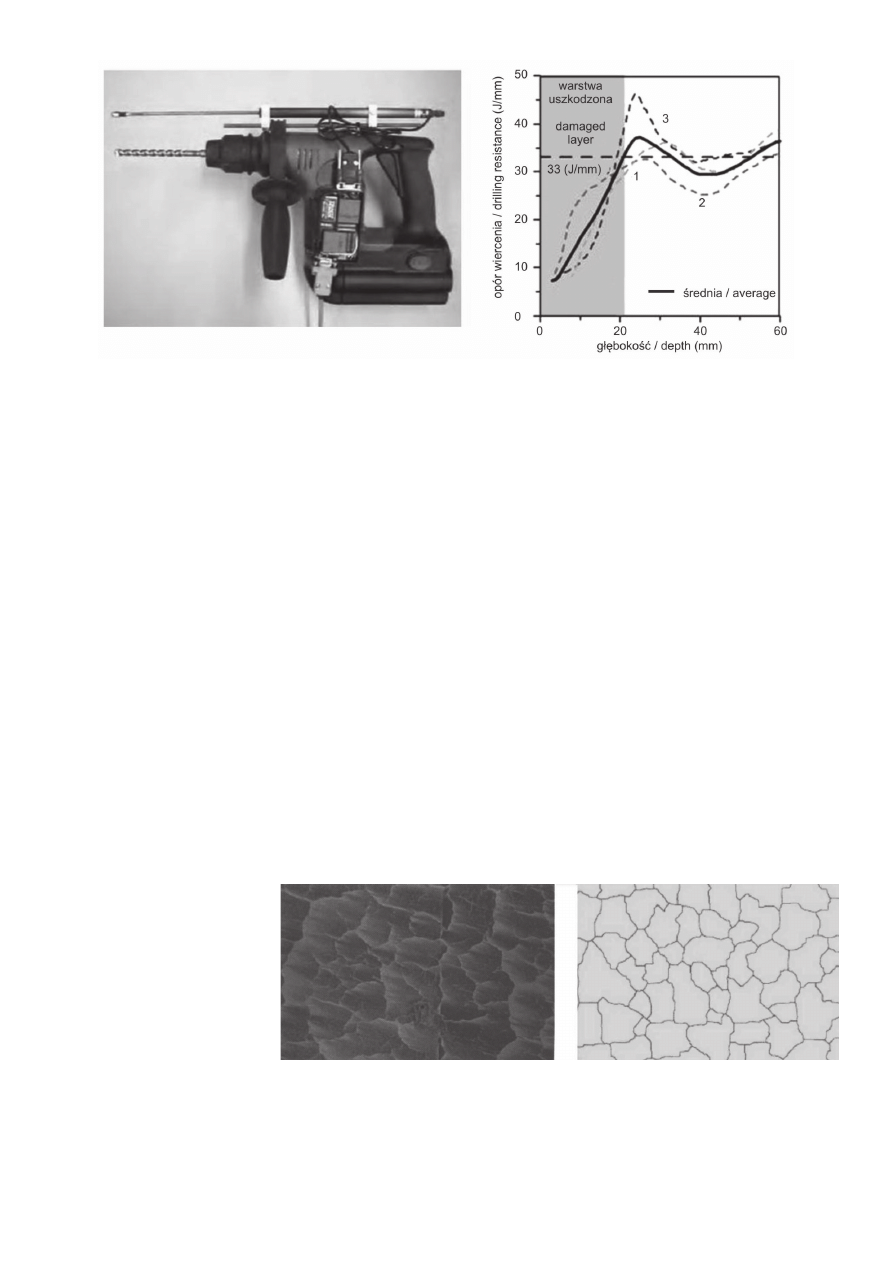
The drilling resistance test method merits special attention. This
is a relatively easy and effective technique making it possible to
evaluate the extent of heat damage to concrete. When examining
concrete properties after the fi re in the Channel Tunnel (8), a statio-
Rys. 5. Zasada badania betonu metodą „pull – out” (CAPO) oraz przykład zależności wytrzymałości betonu na ściskanie od siły wyrywającej (British
Institute of Non Destructive Technics, UK)
Fig. 5. CAPO concrete testing illustration and an example of the relationship between the compressive strength of concrete and its holding strength
(British Institute of Non Destructive Testing, UK)
CWB-4/2009
173
stan naprężeń, który prowadzi do jego miejscowego zniszczenia.
Ustalone doświadczalnie zależności (rysunek 5) pozwalającą na
oszacowanie wytrzymałości betonu na ściskanie.
Metoda destrukcji wewnętrznej (BRE internal fracture) została
opracowana przez Building Research Establishment (14). W bada-
nym materiale wierci się otwór o średnicy 6 mm i głębokości 30-35
mm. W otwór wprowadza się kotwy z tuleją samorozprężającą na
głębokość 20 mm. Dokręcenie głowicy kluczem dynamometrycz-
nym powoduje wyrwanie kotwy (rysunek 6). Bezpośrednią miarą
jakości betonu jest znaleziona wartość momentu obrotowego, która
następnie przeliczana jest na wytrzymałość na ściskanie.
Na szczególną uwagę zasługuje metoda pomiaru oporu wierce-
nia. Jest to stosunkowo łatwa i skuteczna metoda pozwalająca
na oznaczenie zasięgu występowania betonu uszkodzonego
wysoką temperaturą. Do oceny stopnia zniszczenia betonu po
pożarze w tunelu La Manche (8) stosowano wiertnicę na podwo-
ziu stacjonarnym, którą wykonano 500 odwiertów, pozwalających
na sporządzenie „mapy” uszkodzeń betonu. W badaniach oporu
wiercenia prowadzonych przez Felicettiego (11) wykorzystano
powszechnie stosowaną wiertarkę udarową, wyposażoną w induk-
cyjny czujnik przemieszczania wiertła oraz miernik poboru energii
elektrycznej (rysunek 7). Informacje uzyskane podczas wiercenia
pozwalają na obliczenie oporu wiercenia, który określa wykonaną
pracę na jednostkę głębokości wykonanego odwiertu (J/mm). Po
przeanalizowaniu wpływu średnicy wiertła oraz doboru nacisku
na wiertło zoptymalizowano te dwa parametry. Przy zastosowa-
niu wiertła średnicy 10 mm i nacisku na wiertło 170 N uzyskano
zadowalającą powtarzalność wyników. Krzywe oporu wiercenia
w funkcji położenia wiertła pozwalają na wyznaczenie głębokości,
na której występuje strefa nieuszkodzonego materiału. Fluktuacje
rejestrowanego sygnału przypisuje się naturalnej niejednorodności
betonu, wynikającej z jego kompozytowej budowy (rysunek 7).
nary drilling rig was used, and the 500 holes drilled made it possible
to compile a “map” of concrete damage. In drilling resistance tests
conducted by Felicetti (11), a general purpose hammer-drill fi tted
with an inductive displacement sensor and a power consumption
meter was used (Fig. 7). The information obtained during drilling
makes it possible to calculate the drilling resistance expressed as
the drilling work per unit of drilling depth (J/mm). After analysing
the impact of drill diameter and drill force, these two parameters
were optimised. Using the spotting drill of diameter equal 10 mm,
and applying a drill force of 170 N, satisfactory result repeatability
was obtained. By plotting drilling resistance against drill position,
the depth at which the undamaged material zone begins can be
clearly determined. Fluctuations in the signal recorded are attri-
buted to the heterogeneous nature of concrete stemming from its
composite structure (Fig. 7).
Techniques enabling the overall assessment of the construction
element occupy a special place among the methods of assessing
fi re damage. These methods exploit physical phenomena related
to the propagation of electromagnetic waves (ground penetrating
radar — GPR) or phenomena related to the propagation of surface
waves (multichannel analysis of surface waves). Both techniques
are geotechnical methods enabling isoline maps to be obtained
that describe the properties of the analysed elements. Promising
results have been obtained by using these techniques to assess
the condition of concrete structures after a fi re (8); however, these
are still pioneering applications that require further research and
analysis.
The concrete surface cracking image analysis technique also
enables the comprehensive assessment of concrete members.
This method, which is based on the analysis of digital photographs,
was developed in order to assess the damage of the lining of the
Channel Tunnel (8). The assumption behind the method is that the
geometry of surface cracks refl ects concrete damage and depends
on the fi re temperature. Digital photographs are processed by com-
Rys. 6. Ilustracja zasady badania betonu metodą destrukcji wewnętrznej [BRE internal fracture(14)] oraz zależność między momentem obrotowym
powodującym niszczenie (Nm) i wytrzymałością na ściskanie (MPa)
Fig. 6. Illustration of the BRE internal fracture (14) method used to test concrete and the relationship between the breaking moment (Nm) and com-
pressive strength (MPa)
174
CWB-4/2009
W metodach oceny uszkodzeń pożarowych specjalne miejsce
zajmują techniki pozwalające na kompleksową ocenę całego ele-
mentu konstrukcyjnego. Metody te wykorzystują zjawiska fi zyczne
związane z rozchodzeniem się fali elektromagnetycznej (georadar)
lub zjawiska związane z rozprzestrzenianiem się fal powierzchnio-
wych, określaną nazwą analizy fal powierzchniowych (Multichannel
Analysis of Surface Waves). Obie techniki zostały zaczerpnięte
z geotechniki i pozwalają na uzyskanie map izolinii właściwości
analizowanych elementów. Obiecujące wyniki uzyskano stosując
te metody do oceny stanu konstrukcji betonowych po pożarze (8),
jednak są to dotychczas zastosowania pionierskie, wymagające
dalszych badań i analiz.
Na kompleksową ocenę elementu betonowego pozwala także
technika analizy obrazu zarysowania powierzchni betonu. Metoda
ta, opierająca się na analizie zdjęć wykonanych techniką cyfrową,
opracowana została do oceny uszkodzeń elementów sklepienia
tunelu pod kanałem La Manche (8). Metoda zakłada, że geometria
zarysowania powierzchni elementu odpowiada uszkodzeniom
betonu związanym z wysokością temperatury spowodowanej po-
żarem. Zdjęcia cyfrowe poddane zo-
stają obróbce za pomocą programu
komputerowego, który oblicza pole
powierzchni, obwód i współczynnik
kształtu obrysu pól tworzonych przez
zarysowania betonu (rysunek 8).
W następnym etapie przeprowadzić
można analizę korelacji pomiędzy
uzyskaną w ten sposób charakte-
rystyką zarysowań, a na przykład
liczbą odbicia sklerometru zmierzo-
ną w środku każdego z pól.
puter software that calculates the surface areas, circumferences
and shape factors of fi elds formed by concrete cracks (Fig. 8). In
the next stage, the correlation between the cracking parameters
thus determined and e.g. the sclerometer rebound index measured
in the centre of each fi eld can be analysed.
2.2. Laboratory Methods
The tests designed to determine the extent to which concrete has
been degraded and to estimate the depth of the damage zone in
fi re-damaged elements that require the sampling of material and
laboratory testing are listed in Group III (Table 1). The tests car-
ried out on concrete core samples are designed to determine the
residual mechanical properties of the damaged concrete or else
to estimate the temperature to which the concrete was exposed
during the fi re.
Laboratory tests aimed at determining the residual mechanical
properties of damaged concrete consist of the direct testing of the
sample material (cores) or the estimation of these values for the
cores sampled using indirect methods.
Rys. 7. Wiertarka stosowana w metodzie pomiaru oporu wiercenia Felicettiego oraz przykład krzywych zużycia energii niezbędnej w funkcji głębokości
odwiertu (11)
Fig. 7. The drill used in Felicetti’s drilling resistance measurement method and an example of recorded variance in the energy required to drill a 1 mm
deep hole depending on drilling depth (11)
Rys. 8. Powierzchnia zarysowanego betonu po pożarze i uzyskany metodą komputerowej analizy obraz
geometryczny zarysowań (8)
Fig. 8. Surface of fi re-damaged concrete and the geometric cracking image obtained by computer analysis
(8)

CWB-4/2009
175
2.2. Metody laboratoryjne
Badania mające na celu ocenę degradacji betonu oraz oszaco-
wanie głębokości występowania uszkodzeń, wymagają pobrania
materiału z elementów uszkodzonych pożarem i ich zbadania
w warunkach laboratoryjnych (grupa III w tablicy 1). Badania
odwiertów mają na celu określenie właściwości mechanicznych
uszkodzonego betonu, bądź też oszacowanie temperatury, jakiej
poddany został beton w czasie pożaru.
Badania laboratoryjne mające na celu określenie właściwości
mechanicznych uszkodzonego betonu dotyczą bezpośrednich
pomiarów na odwiertach lub oszacowania tych właściwości me-
todami pośrednimi.
Do pomiaru wytrzymałości odwiertów stosuje się metody zawarte
w normach PN-EN 206 i PN-EN 12540-1. Normy te precyzują
średnicę i wysokość odwiertu, a także sposób przygotowania
próbek. Ważne znaczenie ma wybór miejsc i liczba zaplanowa-
nych odwiertów. Pierwsze odwierty powinny zostać wykonane
w miejscach występowania betonu nieuszkodzonego, w celu oceny
właściwości materiału w stanie nienaruszonym. Następnie należy
wykonać odwierty w miejscach występujących uszkodzeń. Wybór
miejsc i ilości odwiertów podyktowany jest zazwyczaj zakresem
planowanych badań oraz rozległością zniszczeń pożarowych.
Ponieważ wiercenia odbywają się w materiale o częściowo
bądź całkowicie zdehydratyzowanej matrycy cementowej zaleca
się, w miarę możliwości, usuwanie pyłu i chłodzenie odwiertów
sprężonym powietrzem, a nie wodą. Z oczywistych względów
należy pamiętać o unikaniu wykonywania odwiertów w miejscach
zagrażających stabilności i nośności badanych elementów oraz
nie należy, w miarę możliwości, prowadzić odwiertów w strefi e
występowania zbrojenia.
W celu oceny dynamicznego modułu sprężystości betonu metoda-
mi pośrednimi stosować można pomiar częstotliwości rezonanso-
wej betonowego plastra uzyskanego przez pocięcie odwiertu wy-
konanego w miejscu uszkodzeń pożarowych (8). Przeprowadzenie
pomiarów na plastrach pochodzących z kolejnych warstw betonu,
pozwala na wyznaczenie profi lu zmian modułu aż do głębokości,
na której występuje beton nieuszkodzony. Do pomiarów stosuje
się analizator częstotliwości rezonansowej wraz z czujnikiem,
młoteczkiem wzbudzającym drgania i odpowiednimi podkładkami
ze spienionej gumy. Wyniki badania próbek pochodzących z róż-
nych głębokości odwiertu pozwalają na określenie profi lu zmian
dynamicznego modułu sprężystości betonu, a w konsekwencji na
oznaczenie zasięgu jego uszkodzeń termicznych.
Metoda ultradźwiękowa może być stosowana również jako pośred-
nia technika pozwalającej na ocenę właściwości mechanicznych
próbek betonu pochodzących z odwiertów. W tym przypadku sto-
suje się układ skrośny czujników, na dwóch średnicach wzajemnie
prostopadłych. Wykonując pomiary na całej długości odwiertu
w odstępach co 1 cm, wyznaczyć można profi l zmian prędkości
fali ultradźwiękowej, a następnie określić zasięg występowania
uszkodzeń (8).
The determination of core strength is based on the guidelines
provided in the PN-EN 206 and PN-EN 12540-1 standards. These
standards stipulate core diameter and height as well as the man-
ner in which samples are to be prepared for testing. An important
aspect of sampling for laboratory test purposes is the choice of lo-
cations and the number of samples collected. Samples should fi rst
be collected from locations where concrete has not been damaged
in order to assess the properties of the intact material. Subsequent
cores should be sampled in damage zones. The choice of locations
and the number of cores sampled is usually determined by the
level of detail required and the extent of fi re damage.
Because the cores are sampled from material whose cement
matrix has been partly or entirely dehydrated, where possible
compressed air should be used instead of water for dust removal
and cooling during drilling. For obvious reasons, samples should
not be collected from locations where this could endanger the
stability and load-bearing capacity of the elements tested; mo-
reover, holes should not be drilled, if possible, in zones where
reinforcement is present.
The resonance frequency method can be used in order to esti-
mate the dynamic modulus of elasticity of concrete using indirect
methods. This consists of the measurement of the resonance
frequency of concrete disks obtained by cutting a sample col-
lected from the fi re damage zone (8). Through determining this
characteristic for disks collected from successive layers of concre-
te, a profi le of modulus changes from the surface layer to the
undamaged concrete layer can be obtained. The measurement
involves a resonance frequency analyser equipped with a sensor,
a hammer that produces vibrations and rubber foam washers.
Results of tests for concrete collected from different depths make
it possible to determine the profi le of changes in the dynamic
modulus of elasticity of concrete, and thus to establish the extent
of thermal damage.
The ultrasound method may also be used as an indirect technique
of assessing the mechanical properties of concrete in the core
samples. In this case, sensors are placed along two perpendicular
diameters. The profi le of changes of the ultrasonic waves speed
can be determined by performing measurements at 1 cm intervals
along the entire length of the core, thus allowing the extent of the
damage zone to be established (8).
The laboratory tests permitting the estimation of the temperature
reached by the concrete use the following techniques: DTA, TGA,
X-ray diffraction, scanning microscopy, thermoluminescence,
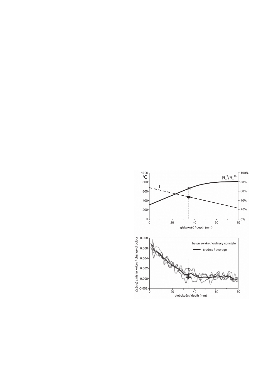
colourimetry, chemical or petrographic analyses. When concrete
is heated, its colour changes. The most pronounced changes in
colour occur in concretes made from siliceous aggregates which
become red or pink when heated to 300–600°C; for tempera-
tures ranging from 600°C to 900°C they turn whitish-grey, and
for temperatures ranging from 900°C to 1000°C their colour is
described as buff (yellow with a grey tinge). Therefore changes
in the mechanical properties of concrete can be estimated on
the basis of its discolouration. In order to describe changes in
176
CWB-4/2009
Badania laboratoryjne mające na celu oszacowanie temperatury,
do której beton został podgrzany polegają na wykorzystaniu DTA,
TGA, rentgenografi i, mikroskopii skaningowej, termoluminescencji,
kolorymetrii, analizy chemicznej, bądź analizy petrografi cznej.
Ogrzewanie betonu powoduje zmianę jego koloru. Najbardziej
intensywne zmiany koloru wykazują betony na kruszywie krze-
mionkowym, które podgrzane do temperatury w zakresie 300-
600°C przybierają kolor czerwony lub różowy, do temperatury
600-900°C białawo-szary, a do temperatury 900°C-1000°C ich
kolor określamy jako płowy (żółty z odcieniem szarości). W efekcie
na podstawie zabarwienia oszacować można zmiany właściwości
mechanicznych betonu. W celu precyzyjnego opisu zmian koloru
wykorzystuje się techniki stosowane do opisu barw w kolorymetrii.
Badania prowadzone przez Faure’a i Hemonda (8) wykonano
podczas diagnostyki betonu w tunelu pod kanałem La Manche. Do
pomiaru barwy stosowano kolorymetr przykładany bezpośrednio
do powierzchni próbek betonu. Metoda stosowana przez Shorta
i innych (15) polegała na obserwacji próbek pod mikroskopem op-
tycznym i analizę zdjęć cyfrowych powiększonego obrazu. Metoda
zastosowana przez Felicettiego (10) oparta była na analizie zmian
koloru betonu w zależności od osiągniętej temperatury (rysunek
9). Zdjęcia odwiertów o długości 80 mm wykonano powszechnie
stosowanym aparatem cyfrowym.
DTA i TGA opierają się na obserwacji przemian fi zykochemicz-
nych zachodzących w próbce betonu podczas jego ogrzewania
w warunkach laboratoryjnych. Przyjmując, że większość przemian
spowodowanych wzrostem temperatury ma charakter nieodwra-
calny, podczas ponownego ogrzewania próbki betonowej pobranej
w miejscu pożaru można stwierdzić na krzywych DTA i TGA brak
efektów termicznych, aż do poziomu temperatury osiągniętej przez
beton podczas pożaru. W wyższych temperaturach powinny poja-
wić się na krzywych charakterystyczne piki związane z przemiana-
mi zachodzącymi w ogrzewanym materiale (8). Korzystając z tej
zasady, poprzez porównanie krzywych odpowiadających próbkom
betonu nienaruszonego oraz pobranych w miejscu pożaru, można
oszacować osiągniętą przez beton temperaturę.
Rentgenografia pozwala na zidentyfikowanie występowania
w materiale faz krystalicznych i oszacowanie ilości tych faz
w próbkach betonu. Stwierdzona obecność lub brak różnych faz
jest podstawą do oszacowania temperatury do jakiej podgrzany
został beton (6, 8).
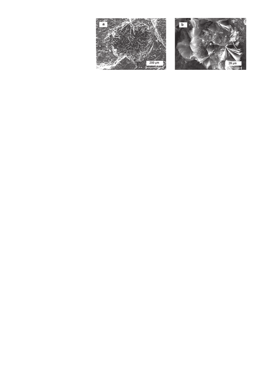
Obserwacje pod mikroskopem skaningowym (8) pozwalają na
oszacowanie temperatury jakiej poddany został beton na podsta-
wie zaobserwowanych przemian fazowych składników mineralnych
oraz obecności charakterystycznych dla danej temperatury faz
mineralnych. Dodatkowo obserwacje odkształceń (skurczu za-
czynu i rozszerzalności termicznej kruszywa) i spowodowanych
nimi zarysowań mogą świadczyć o osiągniętej przez materiał
temperaturze. Obserwacje prowadzi się zarówno na przełamach
jak i na zgładach. Obserwacje mikroskopowe pozwalają na stwier-
dzenie obecności igiełek ettringitu potwierdzające, że beton nie
przekroczył temperatury wyższej niż 100°C (rysunek 10a), bądź
na obserwację rekrystalizacji portlandytu w formach podobnych
colour in a precise manner, colourimetry description techniques
are used. The tests conducted by Faure and Hemond (8) were
performed during the diagnostic examination of concrete in the
Channel Tunnel . In colour measurements, a colourimeter was
used directly on the surface of concrete samples. The method
used by Short et al. (15) consists of samples analysing under an
optical microscope and analysing magnifi ed digital photographs.
The method used by Felicetti (10) consists of analysing changes
in concrete colour depending on the temperature reached (Fig.
9). Photographs of 80 mm long cores were taken using a general
purpose digital camera.
DTA and TGA are methods based on the examination of physico-
chemical changes occurring in concrete during heating in labora-
tory conditions. Assuming that most changes caused by exposure
to temperature are irreversible, during the second heating of
a concrete sample collected from a fi re scene, no visible changes
can be observed on DTA and TGA curves until the temperature
to which the concrete was exposed during the previous heating is
reached. When this level is exceeded, characteristic peaks appear
on the curves that correspond to changes occurring in the material
when heated to the temperature in question (8). Therefore, by
comparing curves for intact concrete with those for the concrete
sampled from the fi re scene, the temperature reached by the
concrete can be estimated.
Rys. 9. Krzywa maksymalnej temperatury (T) oraz względnej resztkowej
wytrzymałości betonu na ściskanie (R
c
T
/R
c
20
) i odpowiadająca tym zmia-
nom zarejestrowana zmiana koloru (wartości uzyskane z 4 odwiertów o
długości 80 mm) (10)
Fig. 9. Maximum temperature (T) and the relative residual compressive
strength of concrete (R
c
T
/R
c
20
) and corresponding changes in the colour
recorded (results for four 80 mm long cores) (10)
CWB-4/2009
177
do „róży pustyni”, która wykazuje, że beton
poddany został działaniu temperatury wyż-
szej od 500°C (rysunek 10b) (8).
Termoluminescencja jest wywołana przez
ogrzewanie substancji, która wcześniej zo-
stała pobudzona przez światło (falę elektro-
magnetyczną) lub promieniowanie przenikli-
we. Metoda polega na podgrzaniu badanego
materiału i zmierzeniu termoluminescencji,
czyli ilości światła wypromieniowanego przez
badany materiał, która jest proporcjonalna do
pochłoniętego promieniowania. Zjawisko to
występuje w fazach krystalicznych. Metoda
ta stosowana jest głównie w archeologii
do datowania ceramiki oraz w geologii do datowania osadów
skalnych. Metoda pozwala na określenie okresu w jakim materiał
został podgrzany oraz maksymalnej temperatury osiągniętej przez
ten materiał. Z tego powodu znalazła ona także zastosowanie
w diagnostyce uszkodzeń pożarowych (8). W technice termolu-
minescencyjnej jarzenie próbek pobranych z uszkodzonych stref
betonu porównuje się z jarzeniem betonu wygrzewanego w warun-
kach laboratoryjnych (warunki wygrzewania powinny odpowiadać
rzeczywistym warunkom pożarowym).
W publikacjach możemy odnaleźć również metody oceny uszko-
dzeń w oparciu o pomiary porowatości za pomocą porozymetrii
rtęciowej (12) oraz średniej wielkości porów lub poprzez ocenę
gęstości mikro-zarysowań (16) (całkowita długość rys na jednostkę
powierzchni).
3. Podsumowanie
Przedstawione w artykule metody oceny uszkodzeń betonu pod-
czas pożaru obejmują techniki powszechnie stosowane do badania
właściwości betonu (metoda sklerometryczna, ultradźwiękowa, lub
„pull-off”, itp) oraz metody adaptowane z innych dziedzin nauki (ter-
moluminescencja, analiza fal powierzchniowych, georadar, itp).
Do dyspozycji inżyniera pozostają zarówno bardzo praktyczne
metody stosowane in situ, jak i zawansowane techniki laborato-
ryjne. Pierwsze z nich pozwalają często na wystarczającą, lecz
jedynie szacunkową i zgrubną, ocenę jakości betonu. Metody
laboratoryjne są bardziej dokładne, jednak droższe i bardziej
czasochłonne. W praktyce zaleca się łączenie kilku metod w celu
uzyskania wystarczająco pełnego i dokładnego obrazu uszkodzeń
elementu betonowego (8, 10, 15).
Literatura / References
1. I. Hager, P. Pimienta, Impact of the polypropylene fi bers on the mechani-
cal properties of HPC concrete, Proceedings of Sixth Rilem Symposium
on Fibre Reinforced Concrete (FRC), BEFIB 2004, September 2004,
Varenna, Italy.
Rys. 10. Obserwacje pod mikroskopem skaningowym: a – igiełki ettryngitu (T < 100°C), b – rekry-
stalizacja portlandytu w formach podobnych do „róży pustyni” ( T > 500°C) (8)
Fig. 10. Scanning microscopy observations: a – ettringite needles (T < 100°C), b – recrystallization
of portlandite in forms resembling to “desert roses” (T > 500°C) (8)
The X-ray diffraction test makes it possible to identify crystalline
phases and estimate the quantity of mineral phases within the
concrete samples. The presence or absence of some phases forms
the basis for estimating the temperature to which the concrete
was heated (6, 8).
The scanning microscope observations (8), enable to estimate
the temperature to which the concrete was exposed by analysing
phase transitions of mineral ingredients and ascertaining the
presence of the mineral phases characteristic of certain tempera-
tures. Moreover, the deformations observed (grout shrinkage and
aggregate thermal expansion) and the cracks caused by them
may help determine the temperature reached by the material.
Both fractured and polished sections are examined. Microscopy
observations make it possible, among other things, to ascertain
the presence of ettringite needles, which would demonstrate that
the concrete was not exposed to a temperature higher than 100°C
(Fig. 10a), or to observe the recrystallisation of portlandite in forms
resembling to “desert roses”, which shows that the concrete was
exposed at temperatures exceeding 500°C (Fig. 10b).
Thermoluminescence is induced by heating substances that were
previously stimulated by light (electromagnetic waves) or pene-
trating radiation. The method consists of heating the material in
question and measuring the thermoluminescence (the amount
of light radiated from the sample), which is proportional to the
radiation absorbed. This phenomenon is observed in crystalline
minerals. The method is primarily used in archaeology for dating
pottery and in geology for dating rock sediments. It enables one
to determine the time at which the material was heated and the
maximum temperature reached. For this reason, it is also used
in fi re-damage assessment (8). In thermoluminescence tests, the
glowing of concrete samples collected from the damage zone is
compared to that of concrete samples heated under laboratory
conditions (heating time and intensity should correspond to real
fi re conditions).
In literature, techniques can also be found whose objective is to
determine the extent of damage by using mercury porosimetry
methods (12), average size of pores or by assessing microcrack
density (16) (total crack length per unit area).

178
CWB-4/2009
2. I. Hager, J. Śliwiński, T. Durica, The impact of heating conditions on
temperature distribution in high performance concrete specimens of vari-
ous shapes and sizes.”, Slovak Journal of Civil Engineering, Volume XIV,
2006/2, p. 8-13.
3. I. Hager, P. Pimienta, Mechanical properties of HPC at high temperatures,
Proc. Int. Workshop fi b Task Group 4.3, Fire Design of Concrete Structures:
What now? What next? Milan, Italy, December, 2004. p. 95-100.
4. I. Hager, Comportement à haute température des bétons à haute
performance - évolution des principales propriétés mécaniques, thèse du
doctorat, Ecole Nationale des Ponts et Chaussées, listopad 2004.
5. Concrete Structures After Fire, Concrete Construction, March 1972,
Vol. 17, No. 3, Concrete Construction Publications, Inc., Addison, IL,
1972, p. 101.
6. Fire design of concrete structures – structural behavior and assessment.
State-of-art report prepared by Task Group 4.3, Fire design of concrete
structures, FIB - Federation International du Béton, July 2008, p. 209.
7. EN 1992-1-2: Eurocode 2 – Design of concrete structures. Part 1.2:
General rules – Structural fi re design, December 2004, p. 97.
8. Présentation des techniques de diagnostic de l’état d’un béton soumis
à un incendie, décembre 2005, n° 62, Laboratoire Central des Ponts et
Chaussées, Paris, France, p. 114.
9. Assessment and Repair of Fire-Damaged Concrete Structures, Technical
Report No . 33, The Concrete Society, London, United Kingdom, 1990.
10. M. Colombo, R. Felicetti, New NDT techniques for the assessment of
fi re-damaged concrete structures, Fire Safety Journal, Vol. 42, Issues 6-7,
September-October 2007, Pages 461-472.
11. R. Felicetti, The drilling resistance test for the assessment of fi re
damaged concrete, Cement and Concrete Composites, Vol. 28, Issue 4,
April 2006, Pages 321-329.
12.http://www.ndtjames.com/catalog/strengthTesting/windsorHighPerfor-
manceProbe_standard.html.
13. D. C. K. Tay, C. T. Tam, In situ investigation of the strength of dete-
riorated concrete, Construction and Building Materials, Vol. 10 (1996), p.
17-26.
14. Internal fracture testing of in-situ concrete: a method of assessing
compressive strength, Building Research Establishment, BRE Information
paper IP22/80, 1980, p. 4.
15. N. R. Short, J. A. Purkiss, S. E. Guise, Assessment of fi re damaged
concrete using color image analysis, Construction and Building Materials,
Vol. 15 (2001) p. 9-15.
16. N. R. Short, J. A. Purkiss, S. E. Guise, Assessment of fi re damaged
concrete using crack density measurements, Structural Concrete, Vol. 5
(2002), p. 137-143.
3. Conclusions
The methods for assessing concrete damage after fi re presented in
the paper include techniques that are commonly used in evaluating
concrete quality (sclerometry method, ultrasonic pulse velocity,
“pull-off” tests, etc.) as well as techniques adapted from other
areas of science (thermoluminescence, multichannel analysis of
surface waves, ground penetrating radar, etc.).
Engineer can choose between very practical in situ techniques and
advanced laboratory ones. The fi rst ones, although often suffi cient,
only enable a sketchy estimation of the concrete’s properties. Labo-
ratory tests are more accurate, but also more expensive and time-
consuming. In practice, several techniques should be combined in
order to obtain a suffi ciently complete and accurate picture of the
damage to the concrete element in question (8, 10, 15).
Wyszukiwarka
Podobne podstrony:
05 Heger I Metody oceny stanu betonu w konstrukcji po pozarze
LABORATORIUM 3 [Nieniszczące metody oceny jakości betonu] Młot-Shmidta, LABORATORIA ĆWICZENIA MATERI
11 diagnostyka i metody oceny stanu technicznego statkow powietrznych
ILOŚCIOWE METODY OCENY STANU CHOREGO Z DYSFUNKCJĄ UKŁADU NERWOWEGO5, Pielęgniarstwo licencjat cm um
Metody oceny stanu odżywienia
2 Metody i techniki wykonywania oceny stanu ogólnego
11 metody badania betonu w konstrukcjiid 12498
4 METODY I TECHNIKI OCENY STANU ŚWIADOMOŚCI
3 METODY I TECHNIKI OCENY STANU OGÓLNEGO
metody i technki wykonywania oceny stanu ogólnego pacjenta
07 03 Bodzak P, Sowa L Stan techniczny zelbetowej konstrukcji budynku magazynowego oraz jej przyda
METODY OCENY PACJENTOW PO UDARZE MOZGU
09 Zastosowanie metody emisji akustycznej do oceny stanu technicznego mostu stalowego
obiektywne metody oceny postawy ciała (win 1997 2003)
Metody oceny spawalnosci stali
więcej podobnych podstron