(23) Install the negative (ground) cable on the bat-
tery.
(24) Cycle the park brake pedal one time. This will
seat the park brake cables and will allow the auto-
matic self adjuster to properly tension the park brake
cables.
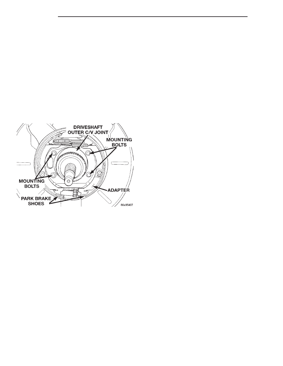
PARK BRAKE SHOES (WITH REAR DISC BRAKES)
On this vehicle, the park brake shoes are removed
from the disc brake adapter with the disc brake
adapter removed from the vehicle.
REMOVE
(1) Set the parking brake. The parking brake is
set to keep the hub/bearing and axle shaft from
rotating when loosening the hub nut.
(2) Raise vehicle. Vehicle is to be raised and sup-
ported on jackstands or on a frame contact type
hoist. See Hoisting in the Lubrication And Mainte-
nance section of this service manual.
(3) Remove the wheel/tire.
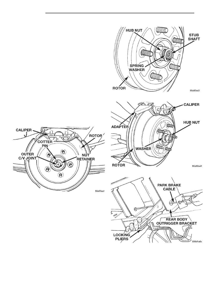
(4) Remove the cotter pin and nut retainer (Fig.
139) from the stub shaft of the outer C/V joint.
(5) Remove the spring washer (Fig. 140) from the
stub shaft of the outer C/V joint.
(6) Remove the hub nut and washer (Fig. 141)
from the stub shaft of the outer C/V joint.
(7) Release the parking brake.
(8) Create slack in the rear park brake cables by
locking the out the automatic adjuster as described.
Grasp the exposed section of front park brake cable
and pull downward on it. Then install a pair of lock-
ing pliers on the front park brake cable just rearward
of the second body outrigger bracket (Fig. 142).
(9) Remove the disc brake caliper to adapter guide
pin bolts (Fig. 143).
(10) Remove rear caliper from adapter using the
following procedure. First rotate rear of caliper up
from the adapter. Then pull the front of the caliper
and the outboard brake shoe anti-rattle clip out from
under the front abutment on the adapter (Fig. 144).
(11) Support caliper to prevent the weight of the
caliper from damaging the flexible brake hose (Fig.
Fig. 139 Cotter Pin And Nut Retainer
Fig. 140 Spring Washer
Fig. 141 Hub Nut And Washer
Fig. 142 Locking Out Automatic Adjuster
5 - 60
BRAKES
NS
REMOVAL AND INSTALLATION (Continued)
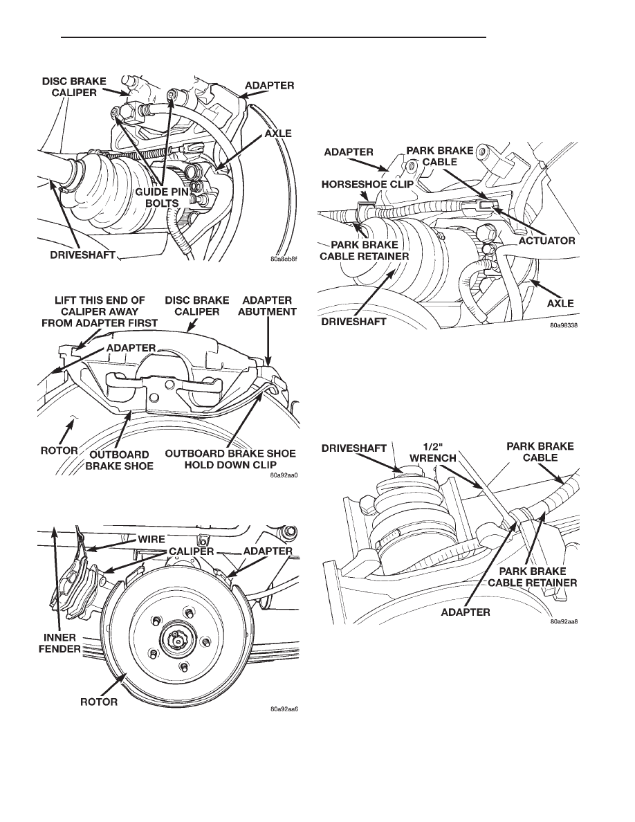
145).
(12) Remove the rotor from the hub/bearing.
(13) Remove the horseshoe clip (Fig. 146) from the
retainer on the end of the park brake cable.
(14) Remove the end of the park brake cable from
the actuator lever on the adapter (Fig. 146).
(15) Remove the end of the park brake cable from
the adapter. Park brake cable is removed from
adapter using a 1/2 wrench slipped over the park
brake cable retainer as show in (Fig. 147) to com-
press the locking tabs on the park brake cable
retainer.
(16) Remove the attaching bolt from the wheel
speed sensor (Fig. 148). Then remove wheel speed
sensor from hub/bearing and adapter.
(17) Remove the hub/bearing to axle mounting
bolts (Fig. 149).
(18) Remove the hub/bearing from the axle and the
stub shaft of the outer C/V joint (Fig. 150).
(19) Remove the adapter from the rear axle.
(20) Mount the adapter in a vise using the anchor
boss for the park brake cable (Fig. 151).
Fig. 143 Removing Caliper Guide Pin Bolts
Fig. 144 Removing / Installing Caliper
Fig. 145 Correctly Supported Caliper
Fig. 146 Park Brake Cable Attachment To Actuator
Fig. 147 Park Brake Cable Removal From Adapter
NS
BRAKES
5 - 61
REMOVAL AND INSTALLATION (Continued)
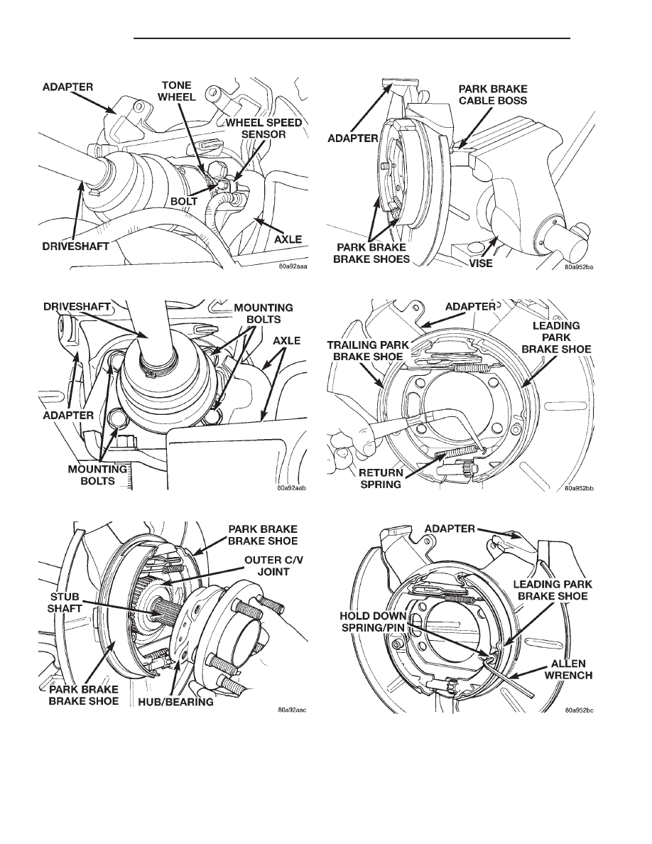
(21) Remove the lower return spring (Fig. 152)
from the leading and trailing park brake shoes.
(22) Remove the hold down spring and pin (Fig.
153) from the leading park brake shoe.
Fig. 148 Speed Sensor Attaching Bolt
Fig. 149 Hub/Bearing Mounting Bolts
Fig. 150 Hub/Bearing Removal And Installation
Fig. 151 Adapter Mounted In Vise
Fig. 152 Lower Return Spring
Fig. 153 Leading Brake Shoe Hold Down Pin And
Spring
5 - 62
BRAKES
NS
REMOVAL AND INSTALLATION (Continued)
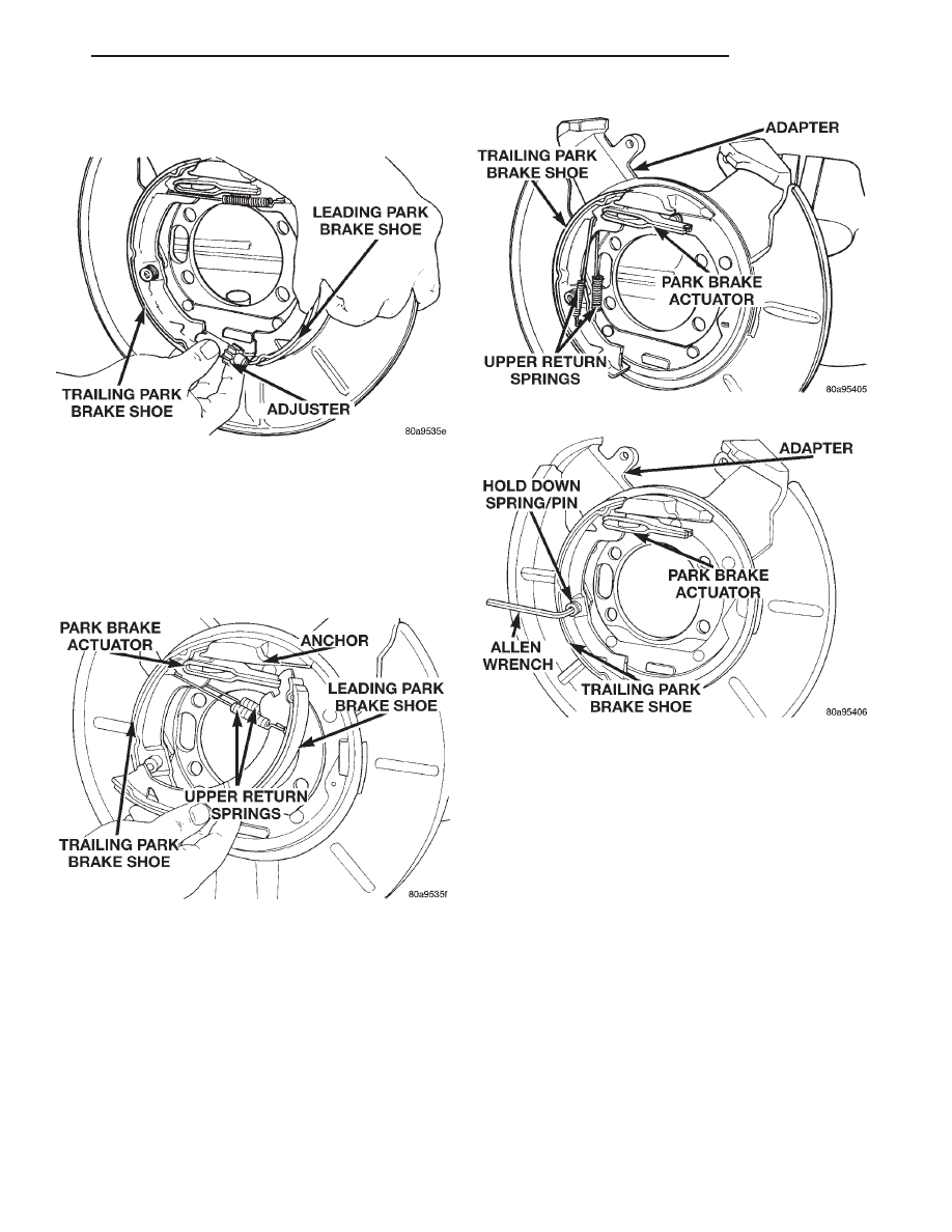
(23) Remove the adjuster (Fig. 154) from the lead-
ing and trailing park brake shoe.
(24) Remove the leading park brake shoe (Fig.
155) from the adapter. Leading brake shoe is
removed by rotating the bottom of the brake shoe
inward (Fig. 155) until the top of the brake shoe can
be removed from the brake shoe anchor. Then remove
the upper return springs (Fig. 155) from the leading
brake shoe.
(25) Remove the upper return springs (Fig. 156)
from the trailing park brake shoe.
(26) Remove the hold down spring and pin (Fig.
157) from the trailing park brake shoe.
(27) Remove the trailing park brake shoe from the
adapter.
(28) Remove the park brake shoe actuator from
the adapter and inspect for signs of abnormal wear
and binding at the pivot point.
INSTALL
(1) Install the trailing brake shoe on the adapter.
NOTE: When the hold down pin is installed, the
long part of the hold down pin is to be positioned
strait up and down. This will ensure that the hold
down pin is correctly engaged with the adapter.
(2) Install the hold down spring and pin (Fig. 157)
on the trailing park brake shoe.
(3) Install the upper return springs (Fig. 156) on
the trailing park brake shoe.
(4) Install the upper return springs on the leading
park brake shoe (Fig. 155). Then position the top of
the leading park brake shoe at the upper anchor and
rotate the bottom of the shoe outward until correctly
installed on the adapter.
(5) Install the adjuster (Fig. 154) between the
leading and trailing park brake shoe.
Fig. 154 Brake Shoe Adjuster
Fig. 155 Primary Brake Shoe Remove/Install
Fig. 156 Upper Return Springs
Fig. 157 Trailing Brake Shoe Hold Down Pin And
Spring
NS
BRAKES
5 - 63
REMOVAL AND INSTALLATION (Continued)
NOTE: When the hold down pin is installed, the
long part of the hold down pin is to be positioned
strait up and down. This will ensure that the hold
down pin is correctly engaged with the adapter.
(6) Install the hold down spring and pin (Fig. 153)
on the leading park brake shoe.
(7) Install the lower return spring (Fig. 152) on
the leading and trailing park brake shoes. When
installing the hold down spring it is to be
installed behind the park brake shoes (Fig.
152).
(8) Install the 4 mounting bolts for the adapter
and hub/bearing into the bolt holes in the axle.
(9) Position the adapter on the 4 mounting bolts
installed in the rear axle (Fig. 158).
(10) Install the hub/bearing on the stub shaft of
outer C/V joint and into the end of the axle. (Fig.
150).
(11) In a progressive criss-cross pattern, tighten
the 4 hub/bearing mounting bolts until the hub/bear-
ing is squarely seated against the axle. Then tighten
the hub/bearing mounting bolts to a torque of 129
N·m (95 ft. lbs.).
(12) Install the wheel speed sensor on the hub/
bearing and adapter. Install the wheel speed sensor
attaching bolt (Fig. 148). Tighten the wheel speed
sensor attaching bolt to a torque of 12 N·m (105 in.
lbs).
(13) Install the park brake cable into its mounting
hole in the adapter. Be sure all the locking tabs
on the park brake cable retainer are expanded
out to ensure the cable will not pull out of the
adapter.
(14) Install the end of the park brake cable on the
park brake actuator lever (Fig. 146).
NOTE: The horseshoe clip must be installed and
installed properly when the park brake cable is
installed in the adapter. The purpose of the horse-
shoe clip is to prevent park brake cable retainer
from moving in the adapter. If horseshoe clip is not
installed the park brake cable retainer will rattle in
the adapter.
(15) Install a NEW horseshoe clip on the park
brake cable retainer (Fig. 146). The horseshoe clip is
installed between the retainer for the park brake
cable and the adapter. Horseshoe clip must be
installed with the curved end of the clip pointing
straight up and the edge of the curved end facing
toward the rear of the vehicle (Fig. 146).
(16) Remove the locking pliers (Fig. 142) from the
front park brake cable.
(17) Adjust the park brake drum-in-hat brake
shoes. See Park Brake Shoe Adjustment in the
adjustment section in this group of the service man-
ual for the proper park brake shoe adjustment proce-
dure.
(18) Install the rotor on the hub/bearing.
(19) Carefully lower caliper and brake shoes over
rotor and onto the adapter using the reverse proce-
dure for removal (Fig. 144).
CAUTION: When installing guide pin bolts extreme
caution should be taken not to crossthread the cal-
iper guide pin bolts.
(20) Install the caliper guide pin bolts (Fig. 143).
Tighten the guide pin bolts to a torque of 22 N·m
(192 in. lbs.).
(21) Clean all foreign material off the threads of
the outer C/V joint stub shaft. Install the washer and
hub nut (Fig. 141) on the stub shaft of the outer C/V
joint.
(22) Set the parking brake.
(23) Tighten the hub nut to a torque of 244 N·m
(180 ft. lbs.).
(24) Install the spring washer (Fig. 140) on the
stub shaft of the outer C/V joint.
(25) Install the nut retainer and cotter pin (Fig.
139) on the stub shaft of the outer C/V joint.
(26) Install the wheel and tire assembly.
(27) Tighten the wheel mounting stud nuts in
proper sequence until all nuts are torqued to half
specification. Then repeat the tightening sequence to
the full specified torque of 129 N·m (95 ft. lbs.).
(28) Remove jackstands or lower hoist.
(29) Fully apply and release the park brake
pedal one time. This will seat and correctly
adjust the park brake cables.
CAUTION: Before moving vehicle, pump the brake
pedal several times to insure the vehicle has a firm
brake pedal to adequately stop vehicle.
Fig. 158 Adapter Installed On Mounting Bolts
5 - 64
BRAKES
NS
REMOVAL AND INSTALLATION (Continued)
Wyszukiwarka
Podobne podstrony:
hamulec ręczny xantia
Hamulec ręczny Citroen C5
Hamulec Ręczny II Citroen C5
HAMULEC RĘCZNY DETALE
hamulec reczny
hamulec reczny Parking
Hamulec ręczny Citroen C5
hamulec tarczowy
hamulec tarczowy 2
hamulec tarczowy 3
hamulec tarczowy
Elektryczny hamulec postojowy i ręczny
hamulec tarczowy
gruczol tarczowy
więcej podobnych podstron