Te
2 8 4 7 0 / 2
Protection components
Zelio Control measurement and control relays
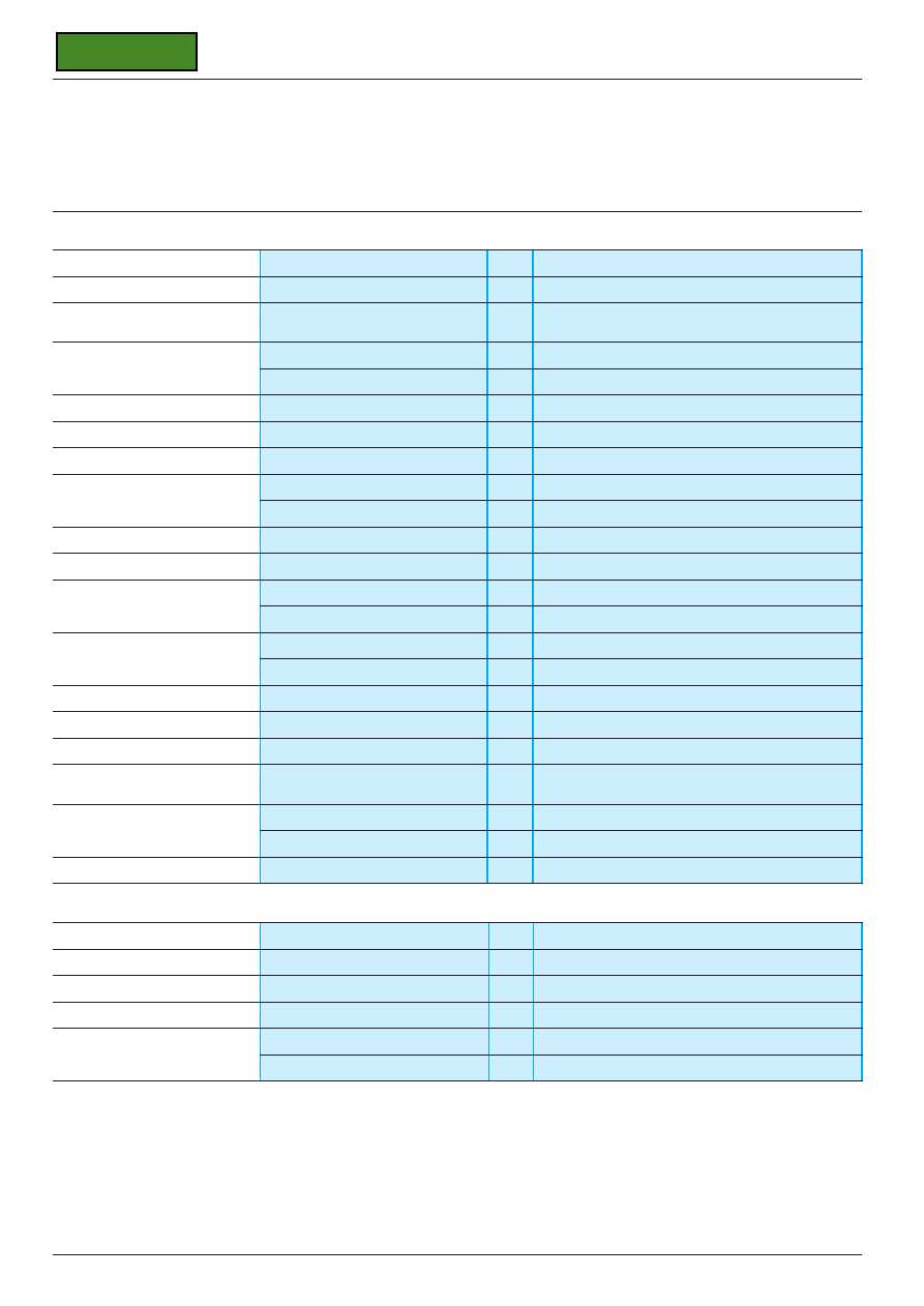
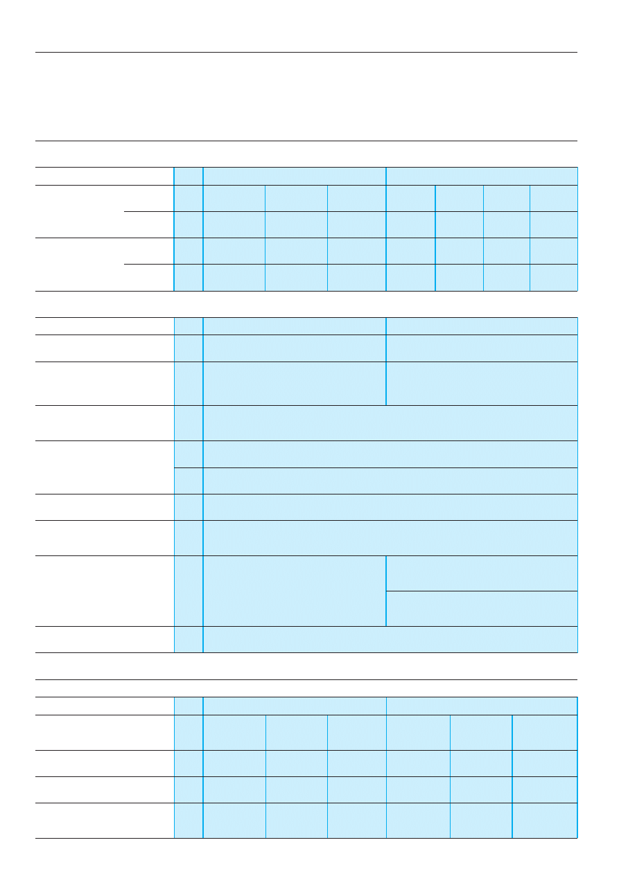
General characteristics
Environment
Conforming to standards
IEC 60255-6, EN 60255-6
Product approvals
CSA, GL, UL, pending
è
marking
Zelio Control measurement relays conform to European
regulations relating to
è
marking
Ambient air temperature
Storage
°
C
- 40…+ 85
around the device
Operation
°
C
- 20…+ 65
Permissible relative humidity range
Conforming to IEC 60721-3-3
15…85 % Environmental class 3K3
Vibration resistance
Conforming to IEC 6068-2-6, 10 to 55 Hz
a = 0.35 ms
Shock resistance
Conforming to IEC 6068-2-27
15 gn - 11 ms
Degree of protection
Casing
IP 50
Terminals
IP 20
Degree of pollution
Conforming to IEC 60664-1
3
Overvoltage category
Conforming to IEC 60664-1
III
Rated insulation voltage
Conforming to IEC
V
500
Conforming to CSA
V
(1)
Test voltage for
Dielectric test
kV
2.5
insulation tests
Shock wave
kV
4.8
Voltage limits
Power supply circuit
0.85…1.1 Uc (2)
Frequency limits
Power supply circuit
50/60
±
5 %
Disconnection value
Power supply circuit
> 0.1 Uc (2)
Mounting position
In relation to normal vertical
Any position
without derating
mounting plane
Connection
Flexible cable without cable end
mm
2
2 x 2.5
Maximum c.s.a.
Flexible cable with cable end
mm
2
2 x 1.5
Tightening torque
N.m
0.6…1.1
Immunity to electromagnetic interference (EMC)
(Application class 2 conforming to EN 61812-1)
Electrostatic discharge
Conforming to IEC 61000-4-2
Level 3 (6 kV contact, 8 kV air)
Electromagnetic fields
Conforming to IEC 61000-4-3
Level 3 (10 V/m)
Fast transients
Conforming to IEC 61000-4-4
Level 3 (2 kV)
Shock waves
Conforming to IEC 61000-4-5
Level 3 (2 kV)
Radiated and
CISPR11
Group 1 class A
conducted emissions
CISPR22
Class A
(1) Value not communicated.
(2) Except RM4-T, see page 28473/5.
Current and voltage measurement relays :
pages 28471/2 to 28472/7
3-phase supply control relays :
pages 28473/2 to 28473/7
Single-phase supply control relays :
pages 28474/2 to 28474/5
Liquid level control relays :
pages 28475/2 to 28475/5
2 8 4 7 0 / 3
Te
Protection components
Zelio Control measurement and control relays
General characteristics
(continued)
Output circuit characteristics
Mechanical durability
In millions of operating cycles
30
Current limit Ith
A
8
Rated operational limits at 70
°
C
24 V
115 V
250 V
Conforming to IEC 60947-5-1/1991
and VDE 0660
AC-15
A
3
3
3
DC-13
A
2
0.3
0.1
Minimum switching capacity
12 V/10 mA
Switching voltage
Rated
V
c
250
Max
V
c
440
Contact material
Nickel Silver 90/10
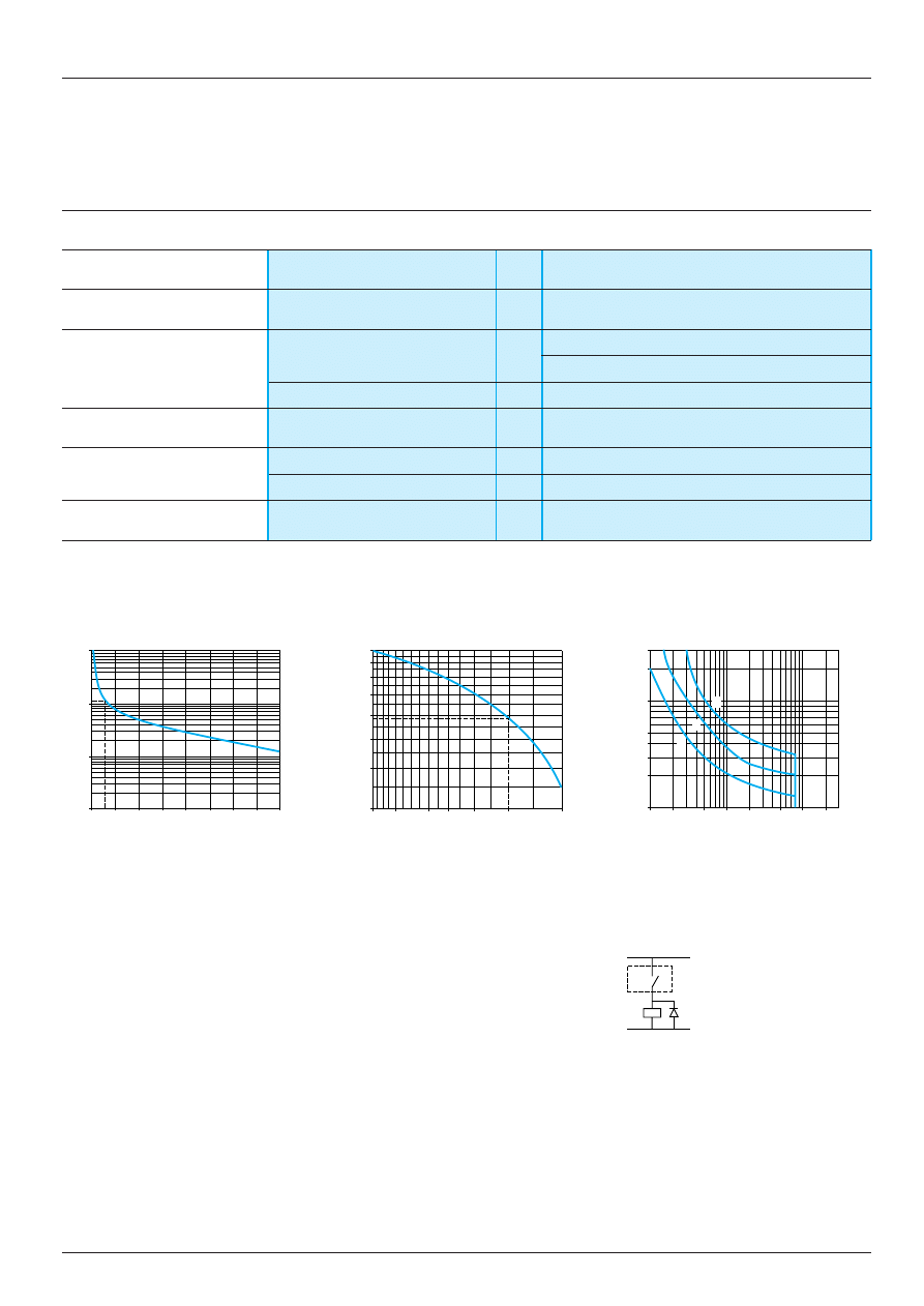
a.c. load
d.c. load
Curve 1
Curve 2
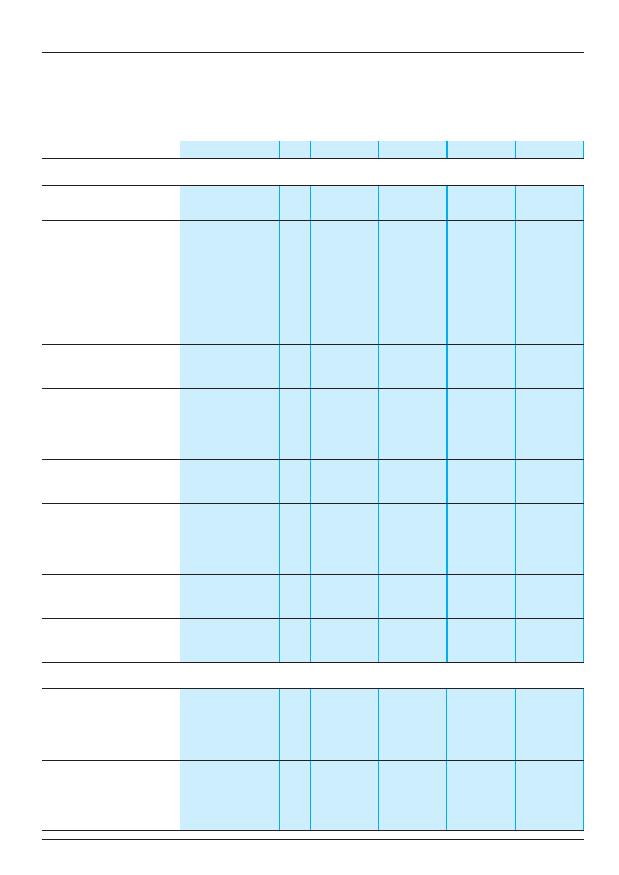
Load limit curve
Electrical durability of the contacts on a resistive
Reduction factor k for inductive loads
load in millions of operating cycles
(applies to values taken from the
durability curve opposite)
Example:
1
L/R = 20 ms
2
L/R with load protection diode
An LC1-F185 contactor supplied with 115 V/50 Hz for a consumption of 55 VA or a current
3
Resistive load
consumption equal to 0.1 A and cos
ϕ
= 0.3
For 0.1 A, curve 1 indicates durability of approximately 1.5 million operating cycles.
As the load is inductive, it is necessary to apply a reduction coefficient k to this number of
cycles, as indicated by curve 2.
For cos
ϕ
= 0.3 : k = 0.6
The electrical durability therefore becomes:
1.5 10
6
operating cycles x 0.6 = 900 000 operating cycles
10
1
0,1
0,01
0
1
2
3
4
5
6
7
8
1
0,6
0,5
0,9
0,8
0,7
0,4
0,3
1
0,8
0,6 0,5
0,4
0,3
0,2
300
40
30
200
100
50
20
10
0,1
0,2
0,5
1
2
5
20
10
1
2
3
Current broken in A
Power factor on breaking (cos
ϕ
)
Current in A
Millions of operating cycles
Reduction factor k
Voltage in V
Current and voltage measurement relays :
pages 28471/2 to 28472/7
3-phase supply control relays :
pages 28473/2 to 28473/7
Single-phase supply control relays :
pages 28474/2 to 28474/5
Liquid level control relays :
pages 28475/2 to 28475/5
RM4
K
+
–
2 8 4 7 1 / 2
Te
Protection components
Zelio Control measurement and control relays
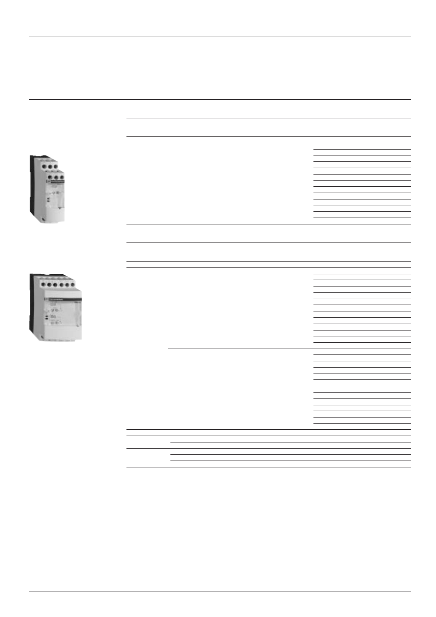
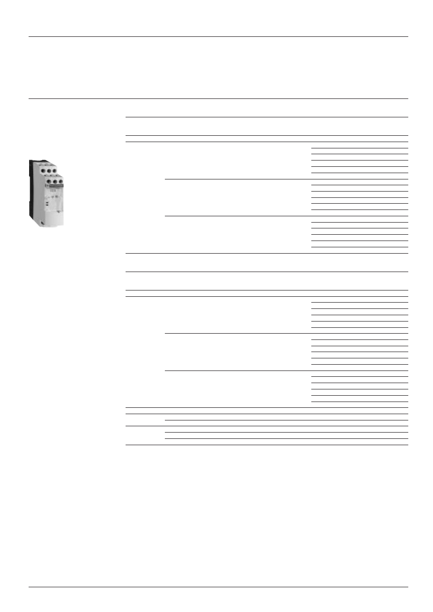
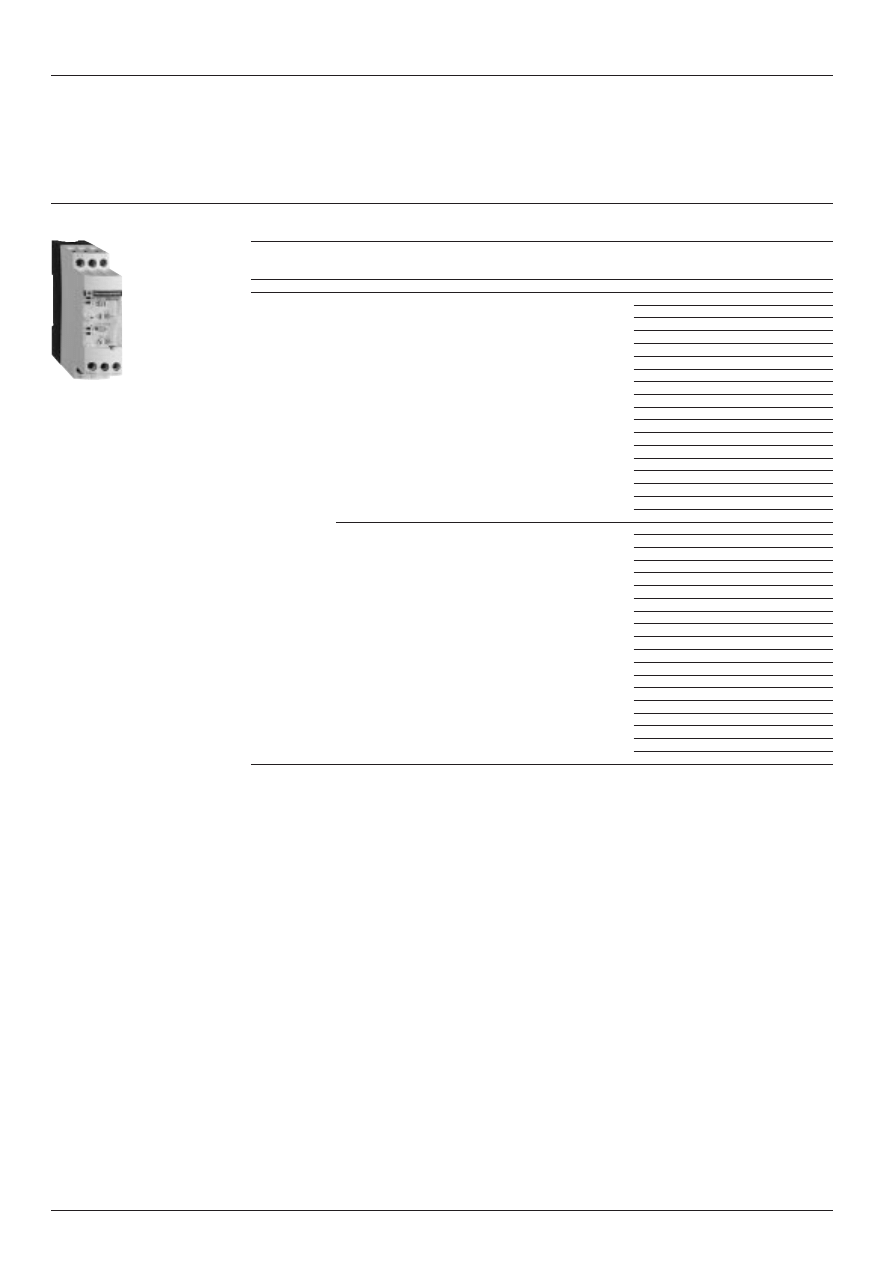
Current measurement relays RM4-JA
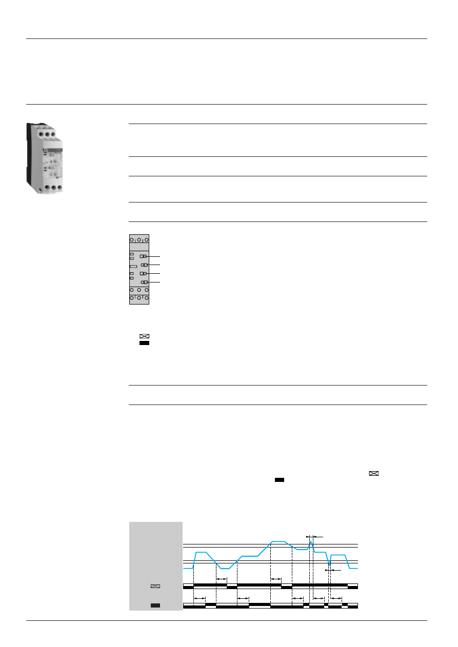
Presentation
Functions
These devices are designed to detect when a preset current threshold is exceeded, on a.c. or d.c. supply.
They have a transparent, hinged flap on their front face to prevent any accidental alteration of the settings.
This flap can be directly sealed.
Type of
Overcurrent
Overcurrent or
Measuring
relay
control
undercurrent control (1)
range
RM4-JA01
Yes
No
3 mA…1 A
RM4-JA31
Yes
Yes
3 mA…1 A
RM4-JA32
Yes
Yes
0.3 A…15 A
Applications:
- excitation control of d.c. machines,
- control of load state of motors and generators,
- control of current drawn by a 3-phase motor,
- monitoring of heating or lighting circuits,
- control of pump draining (undercurrent),
- control of overtorque (crushers).
- monitoring of electromagnetic brakes or clutches.
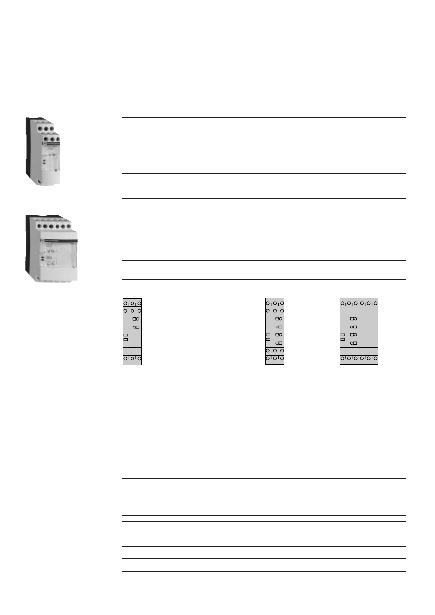
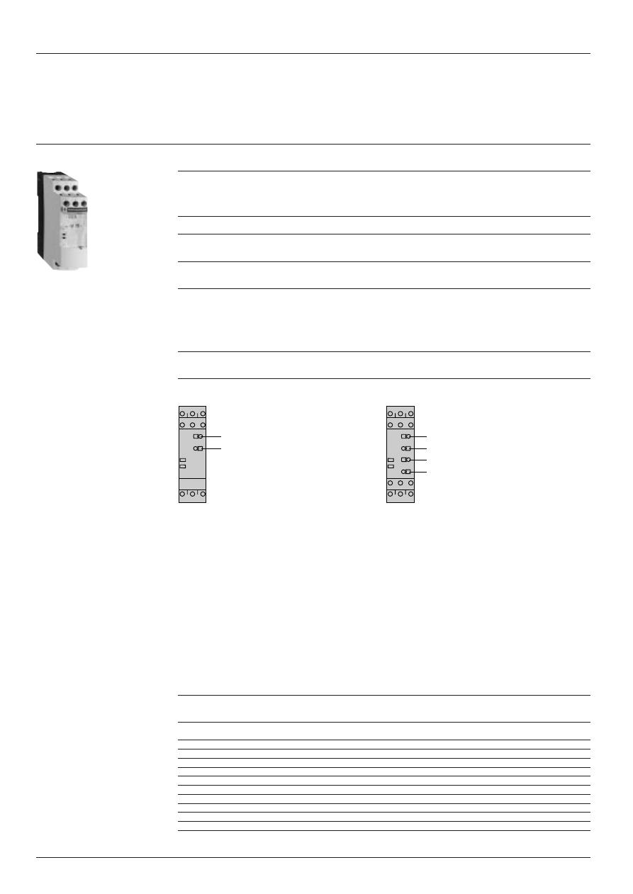
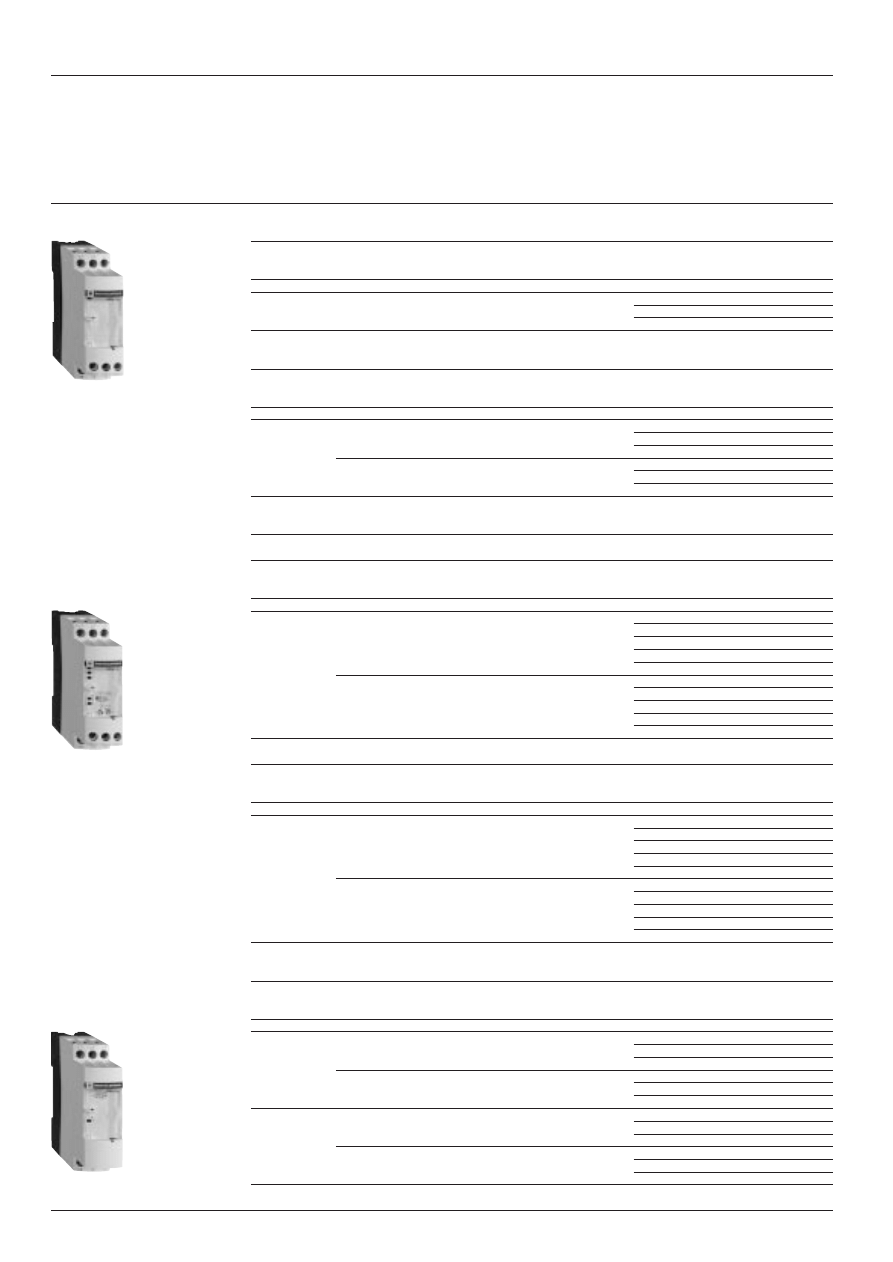
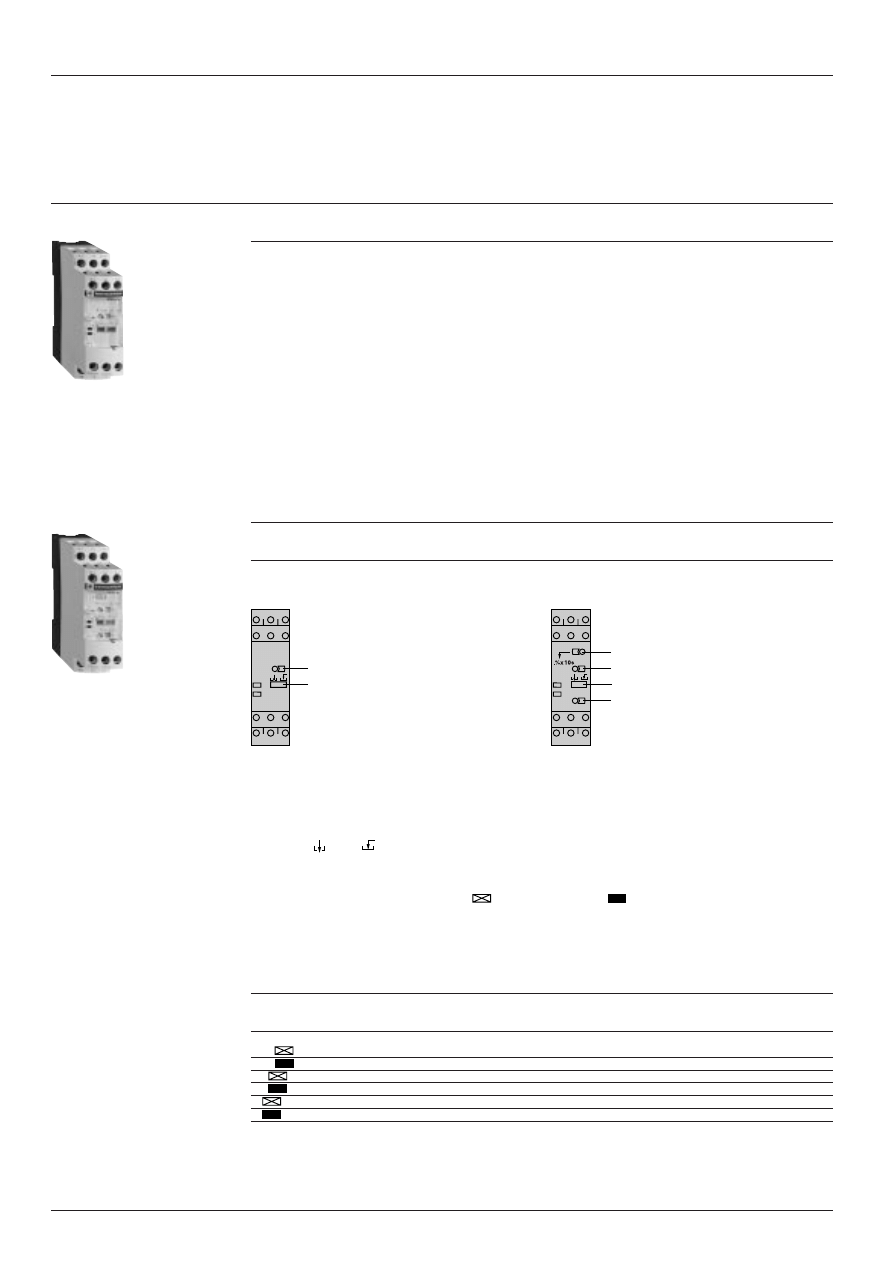
Description
RM4-JA01
RM4-JA31
RM4-JA32
Width 22.5 mm
Width 22.5 mm
Width 45 mm
1
Adjustment of current threshold as % of setting range max. value.
2
Hysteresis adjustment from 5 to 30 % (2).
3
Fine adjustment of time delay as % of setting range max. value.
4
10-position switch combining:
- selection of the timing range: 1 s, 3 s, 10 s, 30 s, no time delay.
- selection of overcurrent (>) or undercurrent (<) detection.
See table below.
R Yellow LED: indicates relay state.
U Green LED: indicates that supply to the RM4 is on.
Table showing details for switch 4
Switch
Function
Time delay
position
(t)
< 0
Undercurrent detection
No time delay
< 1
Undercurrent detection
0.05 to 1 s
< 3
Undercurrent detection
0.15 to 3 s
< 10
Undercurrent detection
0.5 to 10 s
< 30
Undercurrent detection
1.5 to 30 s
> 0
Overcurrent detection
No time delay
> 1
Overcurrent detection
0.05 to 1 s
> 3
Overcurrent detection
0.15 to 3 s
> 10
Overcurrent detection
0.5 to 10 s
> 30
Overcurrent detection
1.5 to 30 s
(1) Selection by switch on front face.
(2) Value of current difference between energisation and de-energisation of the output relay (% of the current threshold
to be measured).
RM4-JA01
Characteristics:
page 28471/4
References:
page 28471/5
Dimensions, schemes:
page 28471/6
Setting-up:
page 28471/7
RM4-JA32
1
2
R
U
1
2
3
4
R
U
1
2
3
4
R
U
2 8 4 7 1 / 3
Te
t:
time delay
B1, B2, B3
RM4-JA
C
Protection components
Zelio Control measurement and control relays
Current measurement relays RM4-JA
Presentation
(continued)
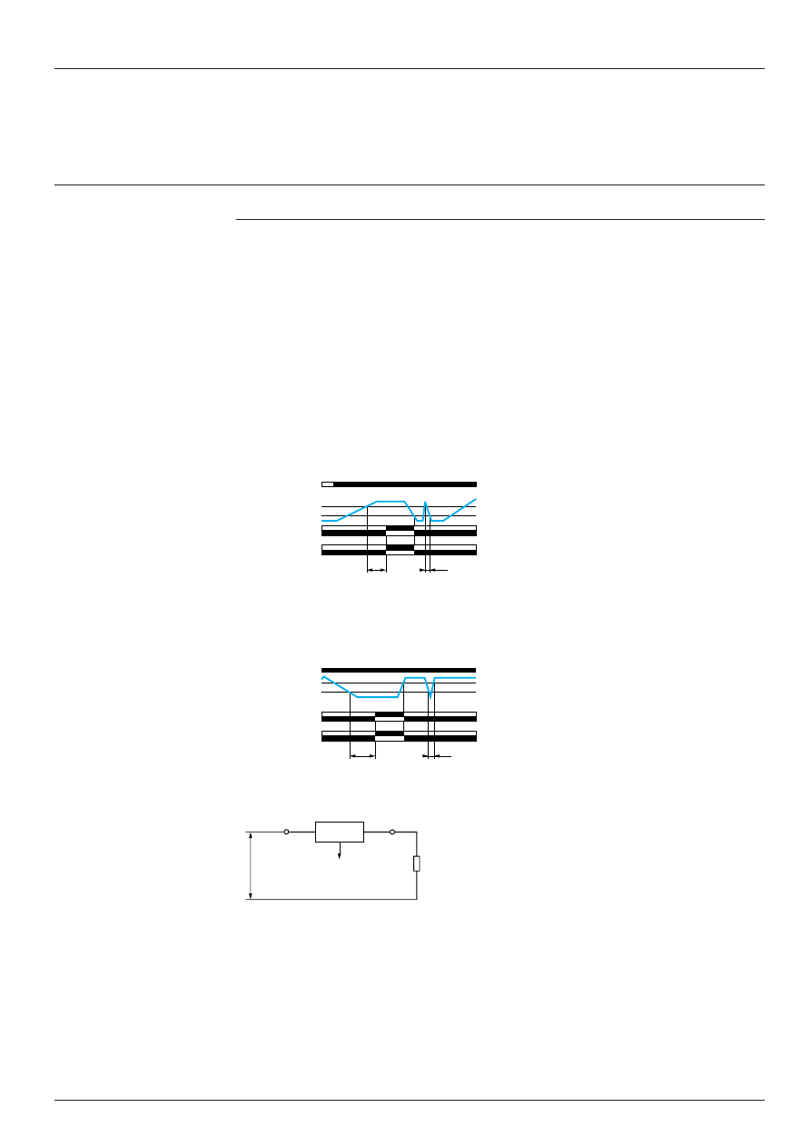
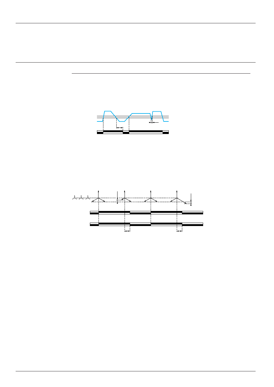
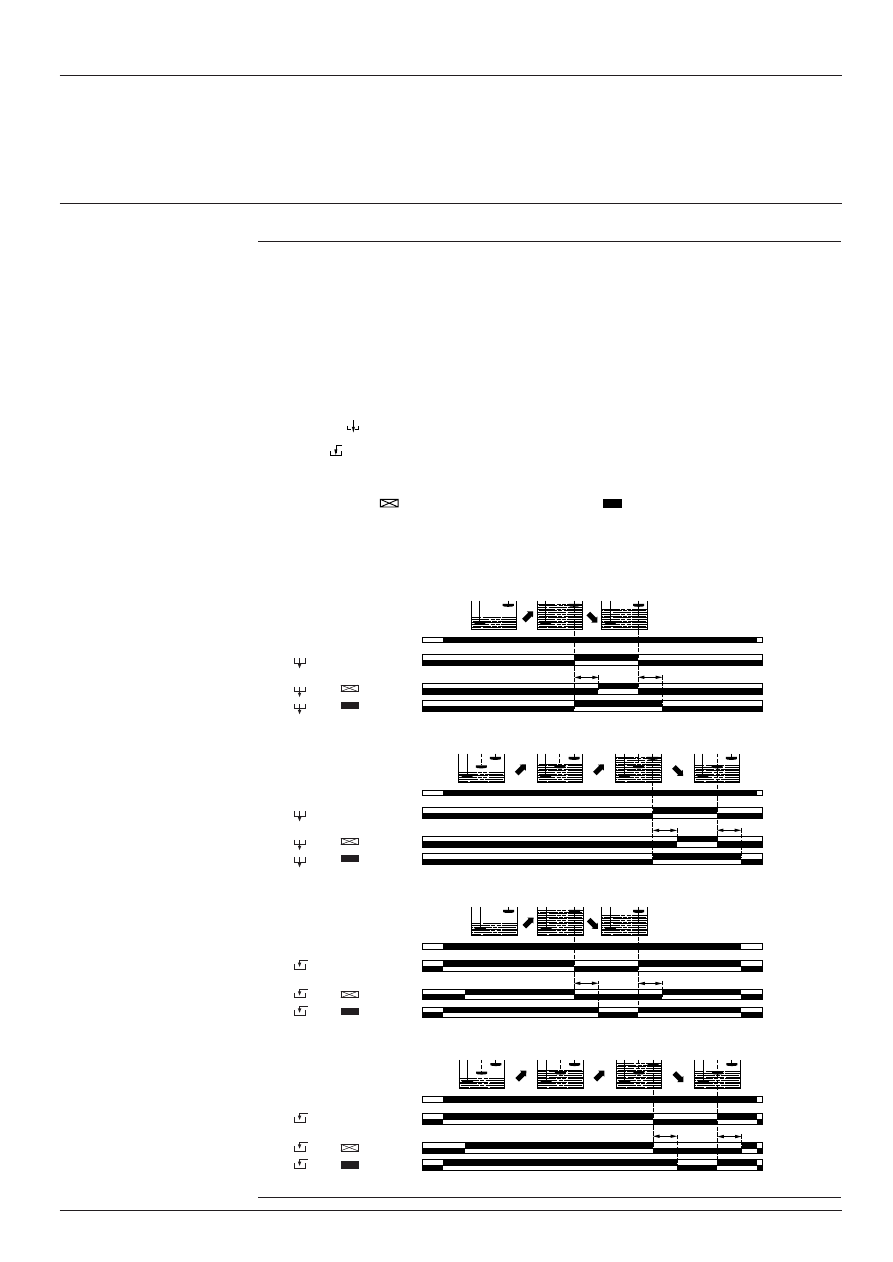
Operating principle
The supply voltage is connected to terminals A1-A2.
The current to be monitored is connected to terminals B1, B2, B3 and C. See diagram below.
Hysteresis is adjustable between 5 and 30 %: for overcurrent h = (IS1 - IS2) / IS1, for undercurrent h = (IS2 - IS1) / IS1.
A measuring cycle lasts only 80 ms, which allows rapid detection of changes in current.
Relay set for overcurrent detection (RM4-JA01 or selector on “>” for model RM4-JA3
i
).
If the current is greater than the setting threshold IS1, the output relay is energised with or without a time delay, depending
on the model. When the current returns to a value IS2 below the threshold, depending on the hysteresis setting, the relay
is instantaneously de-energised.
Relay set for undercurrent detection (selector on “<”, model RM4-JA3
i
only).
If the current is less than the threshold setting IS1, the output relay is energised with or without a time delay, depending
on the model. When the current returns to a value IS2 above the threshold, depending on the hysteresis setting, the relay
is instantaneously de-energised.
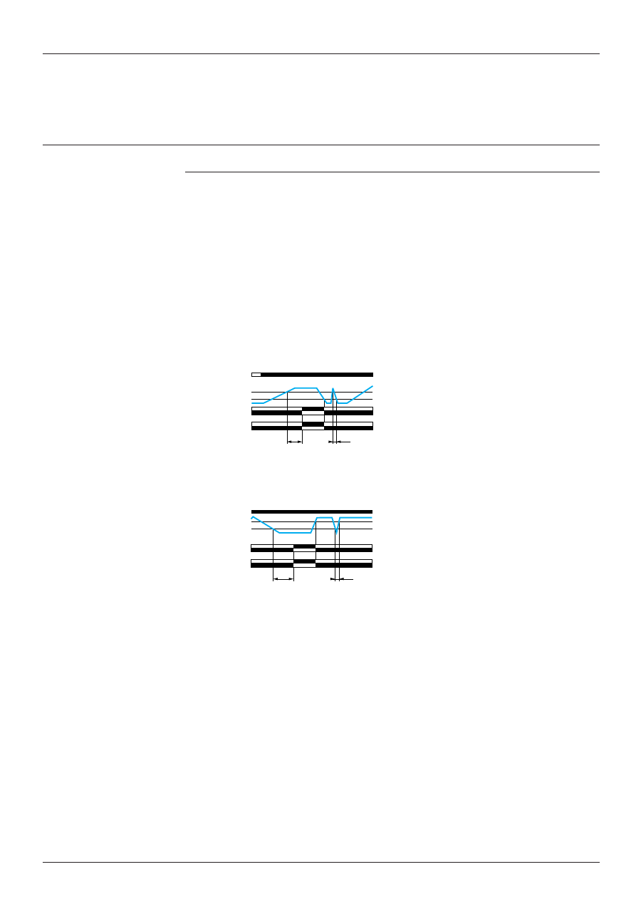
Function diagrams:
Overcurrent detection
Undercurrent detection
Note: The measurement ranges can be extended by means of a current transformer, the secondary of which is connected
to the terminals of the corresponding RM4, or by means of a resistor connected in parallel with the measuring input (see
example page 28471/7 “Setting-up”).
Current
measured
Relay
t
< t
IS1
IS2
15-18
15-16
25-28
25-26
A1-A2
U supply
t
< t
IS1
IS2
15-18
15-16
25-28
25-26
A1-A2
Current
measured
Relay
U supply
Characteristics:
page 28471/4
References:
page 28471/5
Dimensions, schemes:
page 28471/6
Setting-up:
page 28471/7
Function “>”
Function “<”
Measurement circuit
U drop < 1 V
Load
2 8 4 7 1 / 4
Te
Protection components
Zelio Control measurement and control relays
Current measurement relays RM4-JA
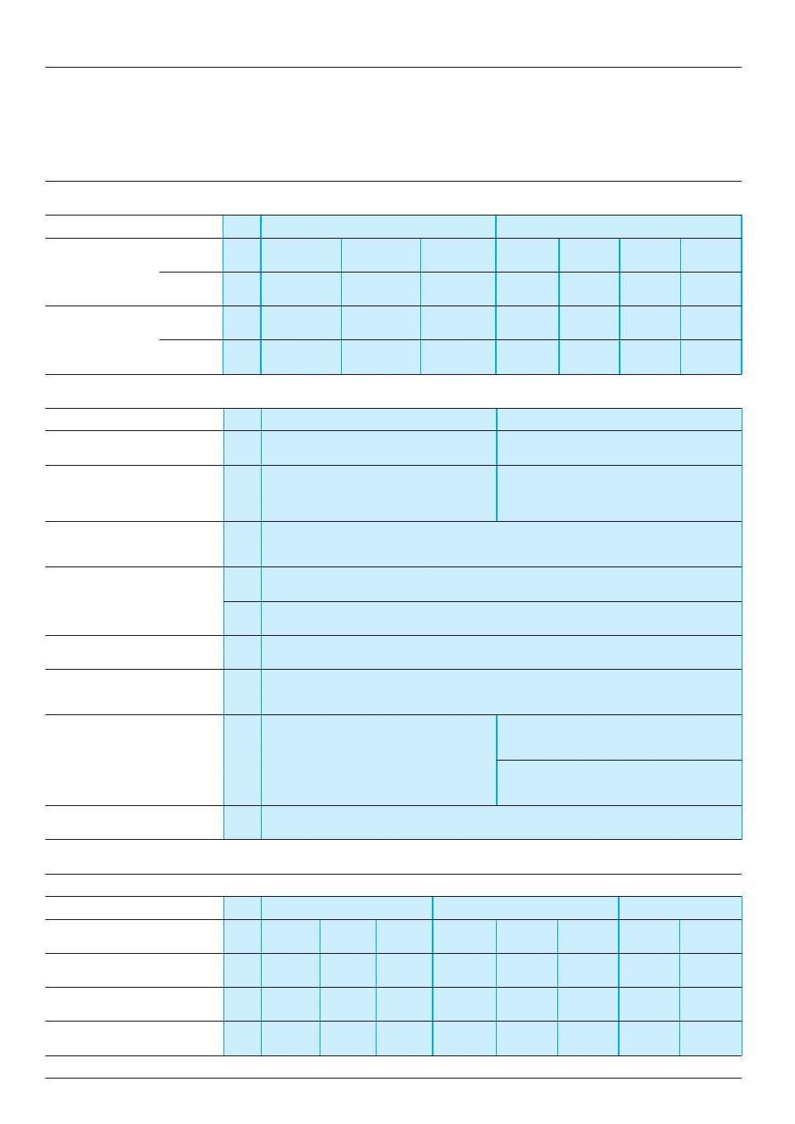
Characteristics
Power supply circuit characteristics
Type of relay
RM4-JA01
RM4-JA31 and RM4-JA32
Rated supply
c
50/60 Hz
V
24
110...130
220...240
24...240
110…130
220...240
380...415
voltage (Un)
a
V
–
–
–
24...240
–
–
–
Average
c
VA
2
1.9…3.3
2.7…3.5
1.5…3.3
1.9…3.3
2.7…3.4
2.7…3
consumption at Un
a
W
–
–
–
1.2
–
–
–
Output relay and operating characteristics
Type of relay
RM4-JA01
RM4-JA31 and RM4-JA32
Number of C/O contacts
1
2
Output relay state
Energised when:
Energised when:
current measured > threshold setting
current measured > threshold setting (“>” function)
current measured < threshold setting (“<” function)
Setting accuracy of the
As % of the full scale value:
±
5 %
switching threshold
Switching threshold drift
%
≤
0.06 per degree centigrade, depending on the permissible ambient temperature
%
≤
0.5, within the supply voltage range (0.85…1.1 Un)
Hysteresis (adjustable)
%
5…30 of the current threshold setting
Setting accuracy of
As % of the full scale value:
±
10 %
the time delay
Time delay drift
%
–
≤
0.07 per degree centigrade, depending on
temperature
≤
0.5, within the supply voltage range
(0.85…1.1 Un)
Measuring cycle
ms
≤
80
Measuring input characteristics
Internal input resistance and permissible overload depending on the current measurement ranges
Type of relay
RM4-JA01 and RM4-JA31
RM4-JA32
Measurement range
3…30 mA
10…100 mA
0.1…1 A
0.3…1.5 A
1…5 A
3…15 A
c
50-60 Hz and
a
Internal input resistance Ri
Ω
33
10
1
0.06
0.02
0.006
Permissible continuous overload
A
0.05
0.15
1.5
2
7
20
Permissible non repetitive overload
A
0.2
0.5
5
10
15
100
for t
≤
3 s
Presentation:
pages 28471/2 and 28471/3
References:
page 28471/5
Dimensions, schemes:
page 28471/6
Setting-up:
page 28471/7
2 8 4 7 1 / 5
Te
Protection components
Zelio Control measurement and control relays
Current measurement relays RM4-JA
References
Current measurement relays: overcurrent detection
Time delay
Current to be measured
Width
Output
Basic reference.
Weight
depending on connection
relay
Complete with code indicating
c
or
a
the voltage code (1)
mm
kg
None
3...30 mA
22.5
1 C/O
RM4-JA01
i
0.172
10...100 mA
0.1...1 A
Current measurement relays: overcurrent or undercurrent detection
Adjustable
Current to be measured
Width
Output
Basic reference.
Weight
time delay
depending on connection
relay
Complete with code indicating
c
or
a
the voltage code (1)
s
mm
kg
0.05...30
3...30 mA
22.5
2 C/O
RM4-JA31
ii
0.172
10...100 mA
0.1...1 A
0.3...1.5 A
45
2 C/O
RM4-JA32
ii
0.204
1...5 A
3...15 A
(1) Standard supply voltages
RM4-JA01
Volts
24
110...130
220...240
c
50/60 Hz
B
F
M
RM4-JA31
Volts
24...240
110...130
220...240
380...415
and RM4-JA32
c
50/60 Hz
MW
F
M
Q
a
MW
–
–
–
Presentation:
pages 28471/2 and 28471/3
Characteristics:
page 28471/4
Dimensions, schemes:
page 28471/6
Setting-up:
page 28471/7
RM4-JA32
RM4-JA01
2 8 4 7 1 / 6
Te
Protection components
Zelio Control measurement and control relays
Current measurement relays RM4-JA
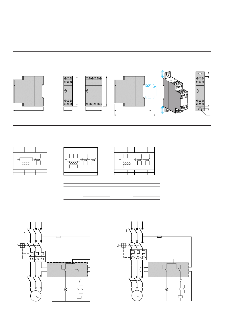
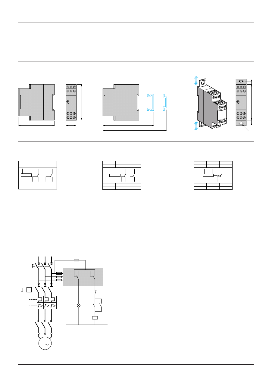
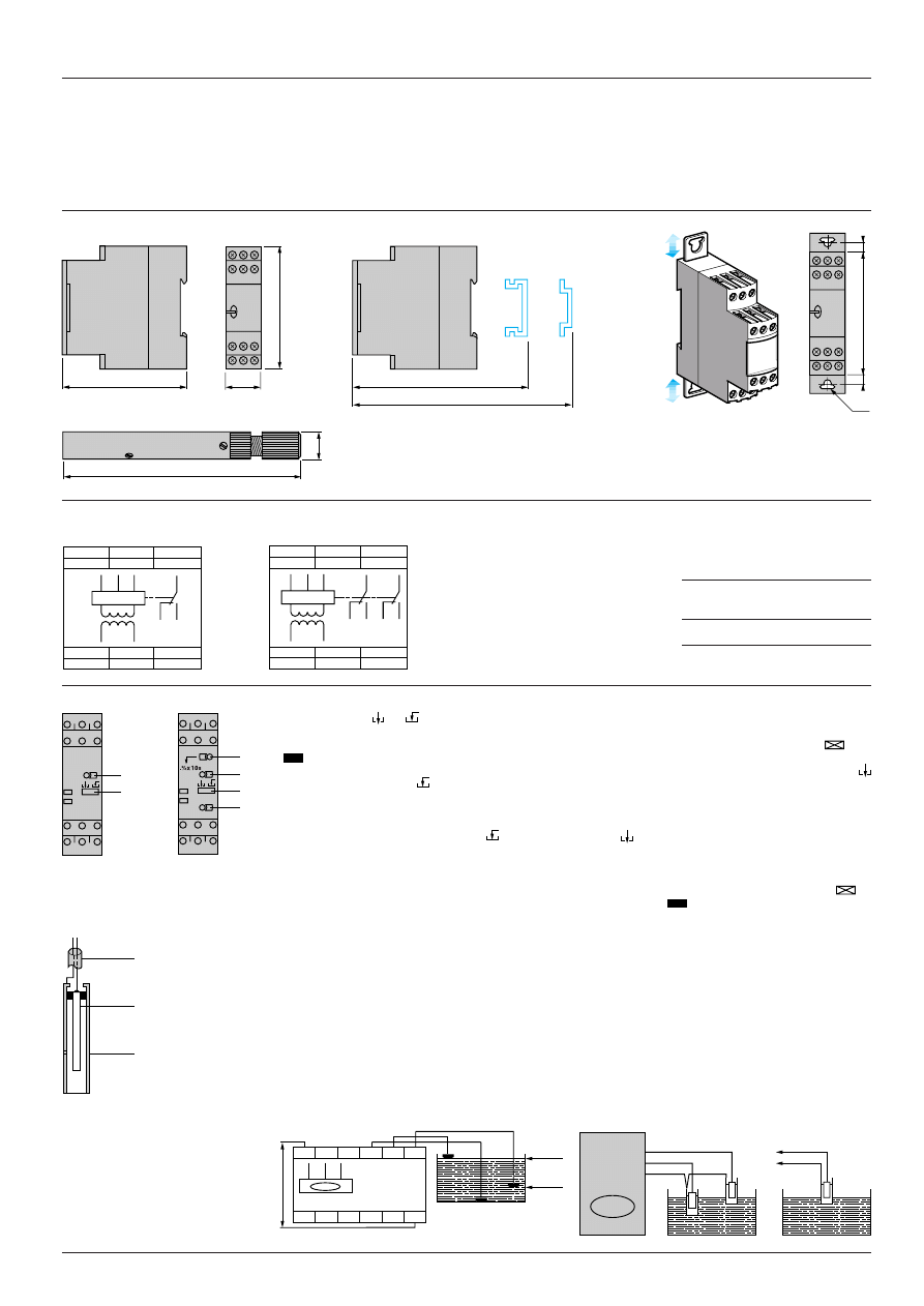
Dimensions, schemes
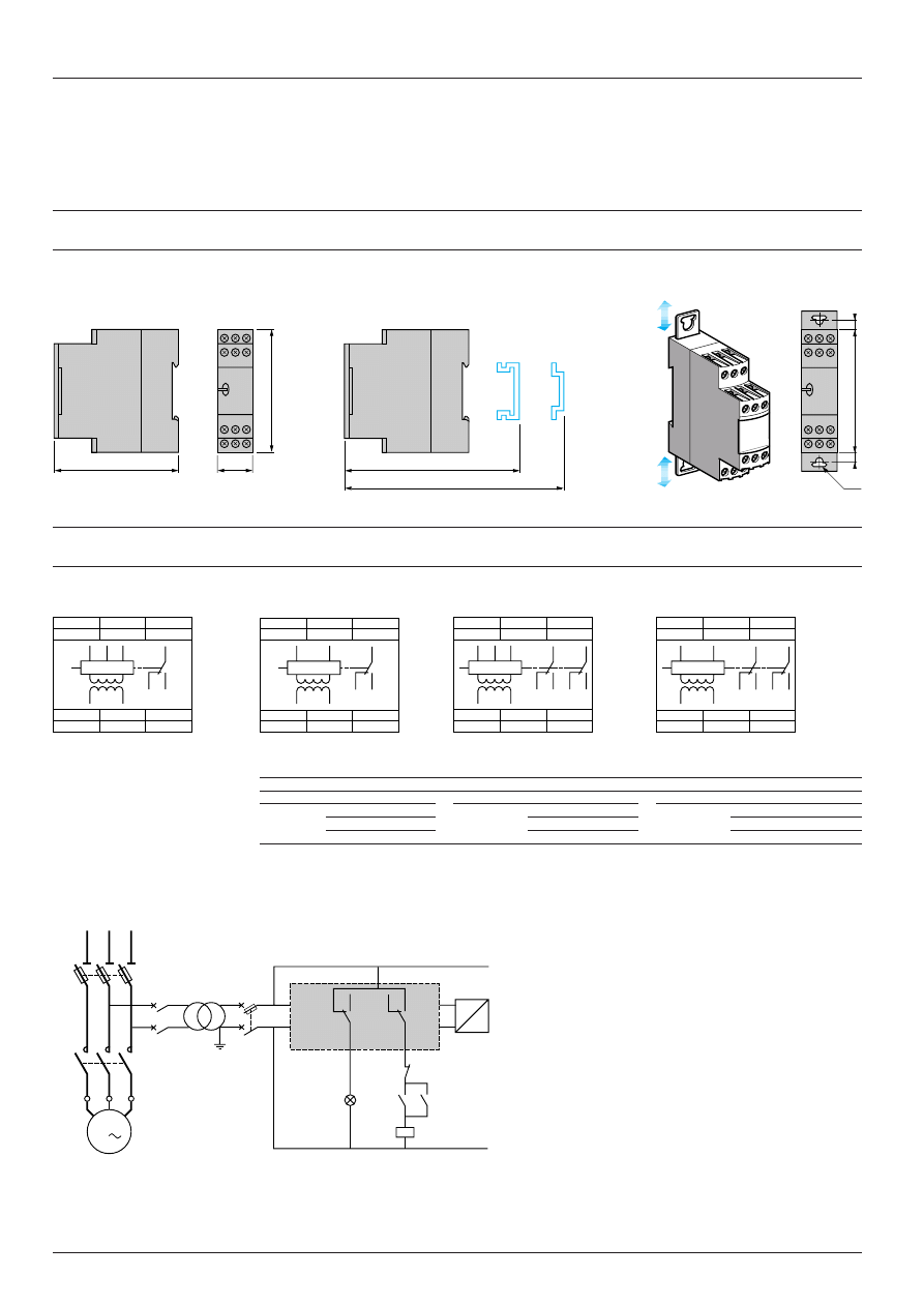
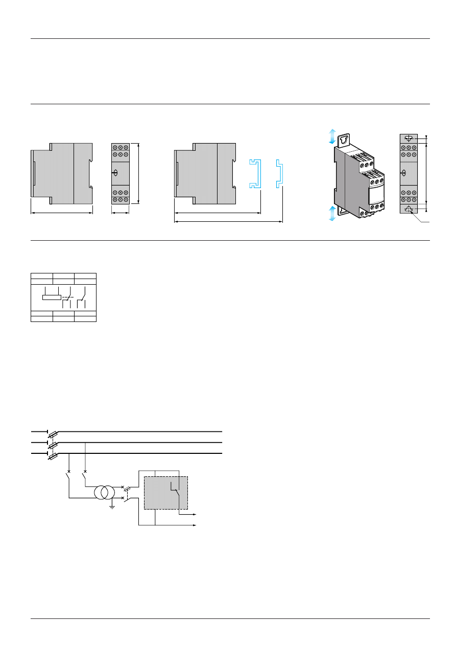
Dimensions
Dimensions
Rail mounting
Screw fixing
RM4-JA (common side view)
RM4-JA
i
1
RM4-JA32
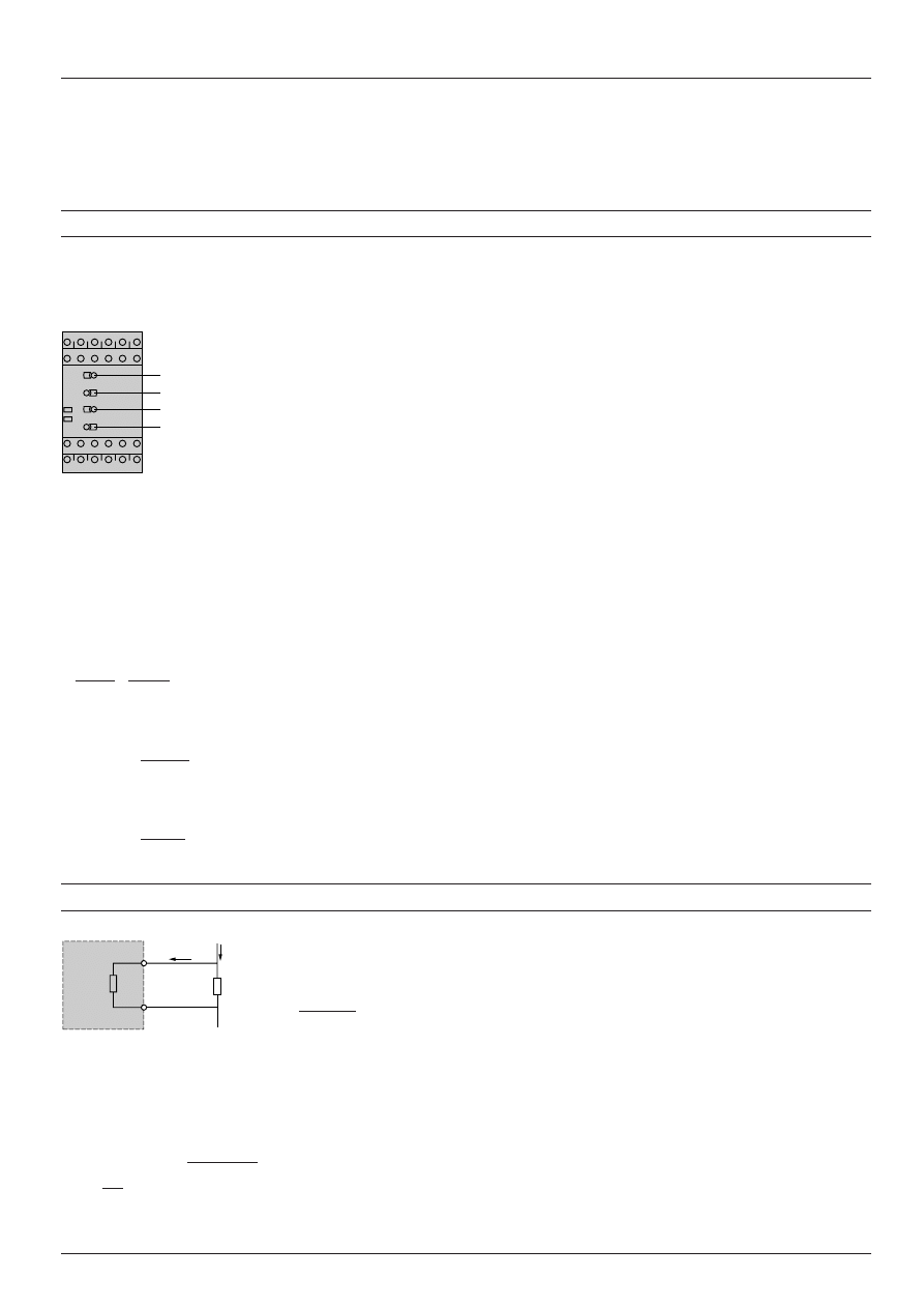
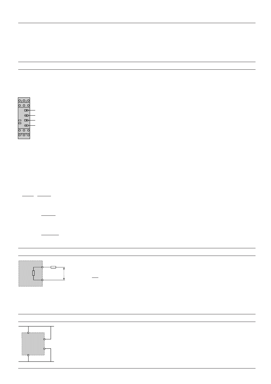
Schemes, connection
Terminal blocks
RM4-JA01
RM4-JA31
RM4-JA32
A1-A2
Supply voltage
Connection and current values to be measured, depending on type of RM4-JA
B1, B2.
Currents to be measured
RM4-JA01
B1-C
3…30 mA
RM4-JA32
B1-C
0.3…1.5 A
B3, C
(see table opposite)
and RM4-JA31 B2-C
10…100 mA
B2-C
1…5 A
B3-C
0.1…1 A
B3-C
3…15 A
Application schemes
Example: detection of blockage on a crusher (overcurrent function)
Current measured
≤
15 A
Current measured > 15 A
Presentation:
pages 28471/2 and 28471/3
Characteristics:
page 28471/4
References:
page 28471/5
Setting-up:
page 28471/7
80
22,5
89,5
82
Ø4
6
6
78
78
45
78
A1
A2
C
B1
B3
B2
26
28
25
18
16
15
18
15
16
B3
28
25
26
B2
B1
A2
A1
C
A1
A2
C
B1
B2
B3
18
16
15
28
26
25
18
15
16
B3
28
25
26
B2
B1
A2
A1
C
A1
A2
C
B1
B3
B2
18
16
15
18
15
16
B3
B2
B1
A2
A1
C
15
18
16
25
28
26
RM4-JA3
KM1
KM1
1/L1
2
3/L2
4
5/L3
6
Q1
2/T1
4/T2
6/T3
1
Q2
3
5
KM1
1
2
3
4
5
6
U1
W1
V1
M1
3
B3
C
A1
A2
N
Overtorque
Start
Stop
15
18
16
25
28
26
RM4-JA3
KM1
KM1
1/L1
2
3/L2
4
5/L3
6
Q1
2/T1
4/T2
6/T3
1
Q2
3
5
KM1
1
2
3
4
5
6
U1
W1
V1
M1
3
B3
C
A1
A2
N
Overtorque
Start
Stop
2 8 4 7 1 / 7
Te
10
(2 x 1/0.1) - 1
Protection components
Zelio Control measurement and control relays
Current measurement relays RM4-JA
Setting-up
Example of overcurrent to be measured
Overcurrent threshold at: 13 A.
Output relay time delay: 5 s.
Reset current threshold: 11 A.
Supply voltage: 127 V
a
.
i
Product selected RM4-JA32MW
Connection of current to be measured B3-C (3 to 15 A)
Adjustments:
i
Adjustment of function and timing range, switch
4
:
- determine whether overcurrent or undercurrent detection is required; in this example, overcurrent.
- determine the timing range, immediately greater than the time required; in this example, 10 s.
- position switch
4
according to the above 2 criteria; in this example, switch
4
on > 10.
i
Fine adjustment of time delay:
Depending on the max. range setting displayed at
4
(in this example: 10 s) use potentiometer
3
to set the required time delay as a % of value
4
.
In this example, the required time = 5 s therefore:
=
= 50 %
Set the time delay potentiometer
3
to 50.
i
Set the current threshold setting potentiometer
1
as a percentage of the maximum value of the measuring range selected when wiring.
In this example: wiring B3-C, max. value of measuring range = 15 A, therefore:
Setting
1
=
= 87 %
Set the current threshold setting potentiometer
1
to 87.
i
Set the hysteresis
2
as a % of the threshold value; in this example:
Setting
2
=
= 15.4 %
Set the hysteresis
2
to 15 (13 - 11 = 2 i.e. 15.4 % of the current to be measured).
Extension of the measuring range
d.c. or a.c. supply
Simply connect a resistor “Rs” to terminals B1-C (or B2, B3-C) on the measuring input.
The relay energisation threshold will be towards the middle of the setting potentiometer range if the value of Rs is in the
region of:
Rs =
where : Ri Internal resistance of input B1-C.
Im Maximum value of threshold setting range.
I
Current threshold to be measured.
Power dissipated by Rs: P = Rs (I -Im/2)
2
Application:
Use of relay RM4-JA31
ii
(10 to 100 mA).
Connection B2-C to measure a threshold of 1 A, knowing that Ri = 10
Ω
for this rating and that Im = 100 mA
The value of Rs will be:
= 0.526
Ω
P = (1 - )
2
x 0.526 i.e. 0.47 W
Select a resistor Rs capable of dissipating at least twice the calculated value, i.e. 1 W for this example, in order to limit temperature rise.
On an a.c. supply, it is also possible to use a current transformer.
1
2
3
4
R
U
t x 100
4
5 x 100
10
13 x 100
15
13 - 11
13
Presentation:
pages 28471/2 and 28471/3
Characteristics:
page 28471/4
References:
page 28471/5
Dimensions, schemes:
page 28471/6
Ri
(2I/Im) - 1
0.1
2
Rs
B1
C
RM4-JA
Ri
Im
I
2 8 4 7 2 / 2
Te
Protection components
Zelio Control measurement and control relays
Voltage measurement relays RM4-UA
Presentation
Functions
These devices are designed to detect when a preset voltage threshold is exceeded, on a.c. or d.c. supply.
They have a transparent, hinged flap on their front face to prevent any accidental alteration of the settings.
This flap can be directly sealed.
Type of
Overvoltage
Overvoltage or
Measuring
relay
control
undervoltage control (1)
range
RM4-UA0
i
Yes
No
50 mV…500 V
RM4-UA3
i
Yes
Yes
50 mV…500 V
Applications:
- d.c. motor overspeed control,
- battery monitoring,
- monitoring of a.c. or d.c. supplies,
- speed monitoring (with tacho-generator).
Presentation
RM4-UA0
i
RM4-UA3
i
Width 22.5 mm
Width 22.5 mm
1
Adjustment of voltage threshold as % of setting range max. value.
2
Hysteresis adjustment from 5 to 30 % (2).
3
Adjustment of time delay as % of setting range max. value.
4
Switch combining:
- selection of the timing range: 1s, 3s, 10s, 30s, no time delay,
- selection of overvoltage (>) or undervoltage (<) detection.
See table below.
R Yellow LED: indicates relay state.
U Green LED: indicates that supply to the RM4 is on.
Table showing details for switch 4
Switch
Function
Time delay
position
(t)
< 0
Undervoltage detection
No time delay
< 1
Undervoltage detection
0.05 to 1 s
< 3
Undervoltage detection
0.15 to 3 s
< 10
Undervoltage detection
0.5 to 10 s
< 30
Undervoltage detection
1.5 to 30 s
> 0
Overvoltage detection
No time delay
> 1
Overvoltage detection
0.05 to 1 s
> 3
Overvoltage detection
0.15 to 3 s
> 10
Overvoltage detection
0.5 to 10 s
> 30
Overvoltage detection
1.5 to 30 s
(1) Selection by switch on front face.
(2) Value of voltage difference between energisation and de-energisation of the output relay (% of the voltage threshold
to be measured).
RM4-UA01
Characteristics:
page 28472/4
References:
page 28472/5
Dimensions, schemes:
page 28472/6
Setting-up:
page 28472/7
1
2
R
U
1
2
3
4
R
U
2 8 4 7 2 / 3
Te
Voltage
measured
Voltage
measured
t:
time delay
Protection components
Zelio Control measurement and control relays
Voltage measurement relays RM4-UA
Presentation
(continued)
Operating principle
The supply voltage is connected to terminals A1-A2.
The voltage to be monitored is connected to terminals B1, B2 or B3 and C.
Hysteresis is adjustable between 5 and 30 %:
for overvoltage h = (US1 - US2) / US1, for undervoltage h = (US2 - US1) / US1.
A measurement cycle lasts only 80 ms, which allows rapid detection of changes in voltage.
Relays set for overvoltage detection (RM4-UA0
i
or selector on “>” for model RM4-UA3
i
):
If the voltage is greater than the threshold setting US1, the output relay is energised, with or without a time delay. When
the voltage returns to a value US2 below the threshold, depending on the hysteresis setting, the relay is instantaneously
de-energised.
Relays set for undervoltage detection (selector on “<”, model RM4-UA3
i
only):
If the voltage is less than the threshold setting US1, the output relay is energised, with or without a time delay. When the
voltage returns to a value US2 above the threshold, depending on the hysteresis setting, the relay is de-energised.
Function diagrams
Overvoltage control
Undervoltage control
Note: the measurement ranges can be extended above 500 V by adding a resistor, see page 28472/7.
The measurement range on
c
supply can be extended by means of a voltage transformer, the secondary of which is
connected to the measuring terminals of the corresponding RM4 .
Characteristics:
page 28472/4
References:
page 28472/5
Dimensions, schemes:
page 28472/6
Setting-up:
page 28472/7
Function “>”
Function “<”
U supply A1-A2
U supply A1-A2
Relay
Relay
t
< t
US1
US2
15-18
15-16
25-28
25-26
t
< t
US1
US2
15-18
15-16
25-28
25-26
2 8 4 7 2 / 4
Te
Protection components
Zelio Control measurement and control relays
Voltage measurement relays RM4-UA
Characteristics
Power supply circuit characteristics
Type of relay
RM4-UA0
i
RM4-UA3
i
Rated supply
c
50/60 Hz
V
24
110...130
220...240
24...240
110…130
220...240
380...415
voltage (Un)
a
V
–
–
–
24...240
–
–
–
Average
c
VA
2
1.9…3.3
2.7…3.5
1.5…3.3
1.9…3.3
2.7…3.4
2.7…3
consumption at Un
a
W
–
–
–
1.2
–
–
–
Output relay and operating characteristics
Type of relay
RM4-UA0
i
RM4-UA3
i
Number of C/O contacts
1
2
Output relay state
Energised when:
Energised when:
voltage measured > threshold setting
voltage measured > threshold setting (“>” function )
voltage measured < threshold setting (“<” function)
Setting accuracy of the
As % of the full scale value:
±
5 %
switching threshold
Switching threshold drift
%
≤
0.06 per degree centigrade, depending on the permissible ambient temperature
%
≤
0.5, within the supply voltage range (0.85…1.1 Un)
Hysteresis (adjustable)
%
5…30 of the voltage threshold setting
Setting accuracy of
As % of the full scale value:
±
10 %
the time delay
Time delay drift
%
–
≤
0.5, within the supply voltage range
(0.85…1.1 Un)
≤
0.07 per degree centigrade, depending on the
rated operating temperature
Measuring cycle
ms
≤
80
Measuring input characteristics
Internal input resistance and permissible overload depending on the current measurement ranges
Type of relay
RM4-UA
i
1
RM4-UA
i
2
RM4-UA
i
3
Measurement range
V
0.05…0.5
0.3…3
0.5…5
1…10
5…50
10…100
30…300
50…500
c
50-60 Hz and
a
Internal input resistance Ri
k
Ω
6.6
43
71
23
112
225
668
1111
Permissible continuous overload
V
20
60
80
90
150
300
400
550
Permissible non repetitive overload
V
25
80
100
100
200
400
500
550
for t
≤
1 s
Presentation:
pages 28472/2 and 28472/3
References:
page 28472/5
Dimensions, schemes:
page 28472/6
Setting-up:
page 28472/7
2 8 4 7 2 / 5
Te
Protection components
Zelio Control measurement and control relays
Voltage measurement relays RM4-UA
References
Voltage measurement relays: overvoltage detection
Time delay
Voltage to be measured
Width
Output
Basic reference.
Weight
depending on connection
relay
Complete with code indicating
c
or
a
the voltage code (1)
V
mm
kg
None
0.05...0.5
22.5
1 C/O
RM4-UA01
i
0.168
0.3…3
0.5…5
1...10
22.5
1 C/O
RM4-UA02
i
0.168
5…50
10…100
30...300
22.5
1 C/O
RM4-UA03
i
0.168
50…500
Voltage measurement relays: overvoltage or undervoltage detection
Adjustable
Voltage to be measured
Width
Output
Basic reference.
Weight
time delay
depending on connection
relay
Complete with code indicating
c
or
a
the voltage code (1)
s
V
mm
kg
0.05...30
0.05...0.5
22.5
2 C/O
RM4-UA31
ii
0.168
0.3…3
0.5…5
1...10
22.5
2 C/O
RM4-UA32
ii
0.168
5…50
10…100
30...300
22.5
2 C/O
RM4-UA33
ii
0.168
50…500
(1) Standard supply voltages
RM4-UA0
i
Volts
24
110...130
220...240
c
50/60 Hz
B
F
M
RM4-JA3
i
Volts
24...240
110...130
220...240
380...415
c
50/60 Hz
MW
F
M
Q
a
MW
–
–
–
Presentation:
pages 28472/2 and 28472/3
Characteristics:
page 28472/4
Dimensions, schemes:
page 28472/6
Setting-up:
page 28472/7
RM4-UA01
2 8 4 7 2 / 6
Te
Protection components
Zelio Control measurement and control relays
Voltage measurement relays RM4-UA
Dimensions, schemes
Dimensions
Dimensions
Rail mounting
Screw fixing
RM4-UA
Schemes, connection
Terminal blocks
RM4-UA01, UA02
RM4-UA03
RM4-UA31, UA32
RM4-UA33
A1-A2
Supply voltage
Connection and voltage values to be measured, depending on type of RM4-UA
B1, B2. Voltages to be measured
RM4-UA
i
1 B1-C
0.05…0.5 V
RM4-UA
i
2
B1-C
1…10 V
RM4-UA
i
3
B2-C
30…300 V
B3, C
(see table opposite)
B2-C
0.3…3 V
B2-C
5…50 V
B3-C
50…500 V
B3-C
0.5…5 V
B3-C
10…100 V
Application scheme
Example: overspeed monitoring (undervoltage function)
Presentation:
pages 28472/2 and 28472/3
Characteristics:
page 28472/4
References:
page 28472/5
Setting-up:
page 28472/7
A1
A2
C
B1
B3
B2
18
16
15
18
15
16
B3
B2
B1
A2
A1
C
A1
A2
C
B1
B3
B2
26
28
25
18
16
15
18
15
16
B3
28
25
26
B2
B1
A2
A1
C
80
22,5
89,5
82
Ø4
6
6
78
78
Q1
1/L1
2
3/L2
4
5/L3
6
Q4
1
2
Q3
2
1
Q2
2
1
15
18
16
25
28
26
RM4-UA
KM1
KM1
A1
A2
B1
C
U
v
KM1
1
2
3
4
5
6
U1
W1
V1
M1
3
Tacho-
generator
Overspeed
Stop
Start
A1
A2
C
B3
B2
18
16
15
18
15
16
B3
B2
A2
A1
C
A1
A2
C
B3
B2
26
28
25
18
16
15
18
15
16
B3
28
25
26
B2
A2
A1
C
2 8 4 7 2 / 7
Te
Protection components
Zelio Control measurement and control relays
Voltage measurement relays RM4-UA
Setting-up
Example of undervoltage to be measured
Undervoltage threshold to be measured: 12 V
a
.
Time delay of the output relay: 20 s.
Reset voltage threshold: 13.2 V.
Supply voltage: 230 V
c
60 Hz.
i
Product selected RM4-UA32M
Connection of voltage to be measured B2-C (5 to 50 V)
Adjustments:
i
Adjustment of function and timing range, switch
4
:
- determine the timing range, immediately greater than the time required, in this example 30 s.
- determine whether overvoltage or undervoltage detection is required, in this example undervoltage.
- position switch
4
according to the above 2 criteria, in this example, switch
4
on < 30.
i
Fine adjustment of time delay:
Depending on the max. range setting displayed at
4
(in this example: 30 s) use potentiometer
3
to set the required time delay as a % of value
4
.
In this example, the required time = 20 s therefore:
=
= 66 %
Set the time delay potentiometer
3
to 66.
i
Set the voltage threshold setting potentiometer
1
as a percentage of the maximum value of the measuring range selected when wiring.
In this example: wiring B2-C, max. value of measuring range = 50 V, therefore:
Setting
1
=
= 24 %
Set the voltage threshold setting potentiometer
1
to 24.
i
Set the hysteresis
2
as a % of the threshold value; in this example:
Setting
2
=
= 10 %
Set the hysteresis
2
to 10.
Extension of the measuring range
d.c. or a.c. supply
Simply connect an additional resistor (Rs) in series with the measuring input B3 or C.
If the value of Rs is in the region of:
Rs = Ri (
- 1) where: Ri
Internal resistance of input B3-C.
Um Maximum value of threshold setting range.
U
Voltage threshold to be measured.
The tripping threshold of the relay will be towards the maximum graduation on the threshold setting potentiometer.
In general, the power consumed by the resistor does not exceed 0.5 W.
For a.c. voltages, it is also possible to use a voltage transformer.
Supply by the measured voltage
For monitoring mains and power supplies, the RM4-UA can be supplied by the voltage to be controlled, provided that:
- the measurement threshold is within the operating range of the product's power supply (0.85…1.1 Uc).
- variations of the voltage to be measured are compatible with the supply and measurement voltage ranges.
t x 100
4
20 x 100
30
12 x 100
50
13.2 - 12
12
Presentation:
pages 28472/2 and 28472/3
Characteristics:
page 28472/4
References:
page 28472/5
Dimensions, schemes:
page 28472/6
1
2
3
4
R
U
U
Um
Rs
C
B3
Ri
U > 500 V
RM4-UA33
A1
A2
B2/B3
C
RM4-UA
2 8 4 7 3 / 2
Te
Protection components
Zelio Control measurement and control relays
3-phase supply control relays RM4-T
Presentation
Functions
These devices are designed to monitor 3-phase supplies and to protect motors and other loads against the faults listed
in the table below.
They have a transparent, hinged flap on their front face to prevent any accidental alteration of the settings. This flap can
be directly sealed.
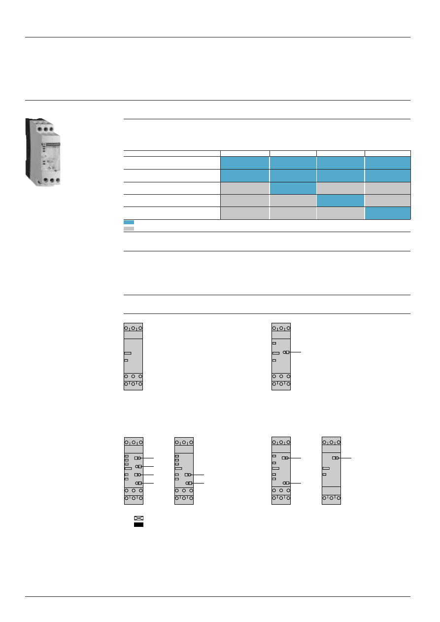
RM4-TG
RM4-TU
RM4-TR
RM4-TA
Monitoring of rotational
direction of phases
Detection of complete failure
of one or more of the phases
Undervoltage detection
Overvoltage and undervoltage
detection (2 thresholds)
Detection of phase asymmetry
(imbalance)
Function performed
Function not performed
Applications
i
Control for connection of moving equipment (site equipment, agricultural equipment, refrigerated trucks).
i
Control for protection of persons and equipment against the consequences of reverse running (lifting, handling,
elevators, escalators, etc.).
i
Control of sensitive 3-phase supplies.
i
Protection against the risk of a driving load (phase failure).
i
Normal/emergency power supply switching.
Presentation
RM4-TG
RM4-TU
R
Yellow LED: indicates relay output state.
R
Yellow LED: indicates relay output state.
< U Red LED: undervoltage fault.
1
Undervoltage setting potentiometer.
RM4-TR31.
RM4-TR33.
RM4-TA3
RM4-TA0
RM4-TR32
RM4-TR34
1
Time delay function selector:
1
Asymmetry threshold setting potentiometer, from 5 to 15 %
Fault detection delayed.
2
Potentiometer for setting time delay, 0.1 to 10 s.
Fault detection extended.
R Yellow LED: indicates relay state.
2
Potentiometer for setting time delay in seconds.
U Green LED: indicates that supply to the RM4 is on.
3
Potentiometer for setting overvoltage as a
A Red LED: phase asymmetry.
direct value.
P Red LED: phase failure or incorrect rotational
4
Potentiometer for setting undervoltage as a
direction of phases.
direct value.
R
Yellow LED: indicates relay state.
U
Green LED: indicates that supply to the RM4 is on.
> U Red LED: overvoltage fault
< U Red LED: undervoltage fault
P
Red LED: phase failure or incorrect rotational
direction of phases.
RM4-T
R
1
R
<U
3
4
1
2
R
U
<U
P
>U
1
2
R
U
<U
P
>U
1
2
R
U
P
A
1
R
Characteristics:
page 28473/5
References:
page 28473/6
Dimensions, schemes:
page 28473/7
2 8 4 7 3 / 3
Te
Protection components
Zelio Control measurement and control relays
3-phase supply control relays RM4-T
Presentation
(continued)
Operating principle
The supply voltage to be monitored is connected to terminals L1, L2, L3 of the product.
There is no need to provide a separate power supply for RM4-T relays; they are self-powered by terminals L1, L2, L3.
i
Monitoring rotational direction of phases and detection of complete failure of one of more of the phases
(RM4-T all models)
When terminals L1, L2, L3 are energised, the relay is energised and the yellow LED comes on if the rotational direction
of phases is correct and if all 3 phases are present.
If one or more of the phases have failed or if the rotational direction is incorrect, the relay is not energised at switch-
on. In normal operation (no fault) the relay is energised; it de-energises instantaneously in the event of failure of one
or more of the phases (any time delay set is not active on these faults).
In the event of failure or absence of a single phase, a voltage greater than the detection threshold (
≈
130 V on RM4-TG,
undervoltage threshold setting on RM4-TU and RM4-TR) can be generated back through the control circuit, thus
preventing detection of the phase failure. In this case, we recommend the use of RM4-TA relays.
The absence of a phase is signalled, on RM4-TR and RM4-TA, by illumination of led “P”.
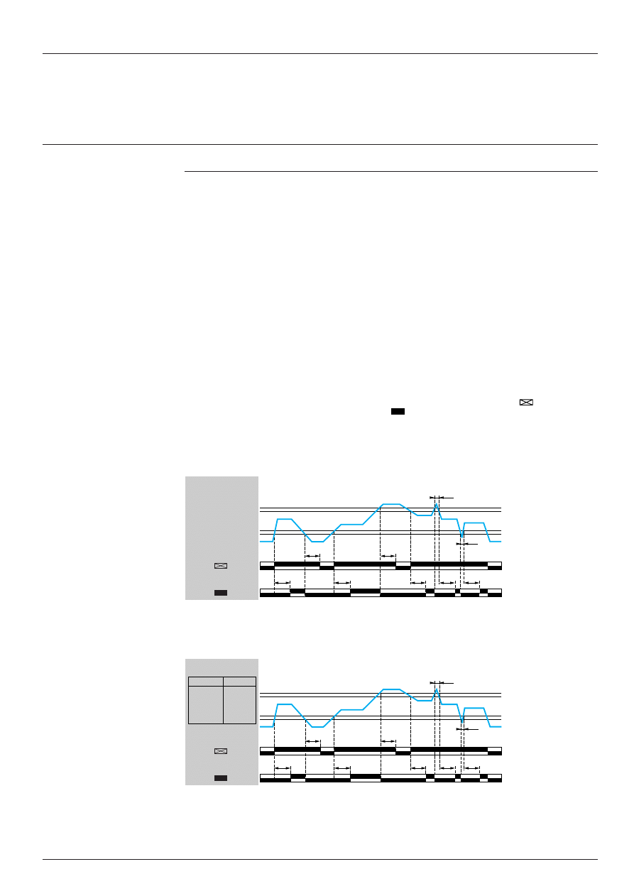
i
Overvoltage and undervoltage detection (RM4-TR):
In normal operation, the relay is energised and LEDs “U” and “R” are illuminated.
If the average of the 3 voltages between phases goes outside the range to be monitored, the output relay is de-
energised:
- overvoltage: the Red LED “> U” illuminates.
- undervoltage: the Red LED “< U” illuminates.
When the supply returns towards its rated value, the relay is re-energised according to the hysteresis value (5%) and
the corresponding red LED goes out.
A selector switch allows selection of an adjustable time delay from 0.1 s to 10 s. With function transient “over” or
“under” voltages are not taken into account. With function all variations above or below are taken into account and
re-energisation of the relay is delayed.
In all cases, in order to be detected, the duration of the overvoltage or undervoltage must be greater than the measuring
cycle time (80 ms).
Function diagram (RM4-TR31, RM4-TR32)
t: time delay
Function diagram (RM4-TR33, RM4-TR34)
t: time delay
t
t
< t
t
t
t
t
t
< t
15/18 25/28
15/16 25/26
15/18 25/28
15/16 25/26
RM4-TR31
RM4-TR32
U
L1 L2 L3
0 Volt
t
t
< t
t
t
t
< t
15/18 25/28
15/16 25/26
15/18 25/28
15/16 25/26
242 V 440 V
230 V 418 V
208 V 378 V
198 V 360 V
RM4-TR33
RM4-TR34
TR33 TR34
U
L1 L2 L3
t
t
0 Volt
Characteristics:
page 28473/5
References:
page 28473/6
Dimensions, schemes:
page 28473/7
Setting > U
0.95 x Setting > U
1.05 x Setting < U
Setting < U
Function
Function
Function
Function
2 8 4 7 3 / 4
Te
Protection components
Zelio Control measurement and control relays
3-phase supply control relays RM4-T
Presentation
(continued)
Operating principle
(continued)
i
Undervoltage detection only (RM4-TU)
In normal operation, the output relay is energised and the yellow LED is illuminated.
If the average of the 3 voltages between phases is less than the undervoltage threshold setting, the relay is de-
energised after 550 ms and the red LED “< U” illuminates.
Function diagram
t: fixed time delay = 550 ms
i
Detection of phase asymmetry (RM4-TA)
In normal operation, the output relay is energised and the yellow and green LEDs are illuminated.
In the event of an asymmetry fault, after a time delay set between 0.1 s and 10 s (on RM4-TA3 only), the output relay
is de-energised, the yellow LED goes out and red LED “A” illuminates (RM4-TA3
i
only).
The relay re-energises when the asymmetry value measured is less than half of the asymmetry value setting
(hysteresis).
Function diagram
t: time delay
Example: asymmetry set at 10 %, mains supply voltage 400 V
- relay de-energisation threshold: 400 - 10 % = 360 V.
10 %
- relay re-energisation threshold: 400 V – ––––
= 380 V.
2
Asymmetry >
set threshold
Relay
Asymmetry >
set threshold
t
< t
0 volt
15/18 25/28
15/16 25/26
U
L1 L2 L3
Characteristics:
page 28473/5
References:
page 28473/6
Dimensions, schemes:
page 28473/7
1.05 x Setting < U
Setting < U
15-18
15-16
25-28
25-26
t
t
L1
L3 L2
L2
L1 L3
L3
L2 L1
2 8 4 7 3 / 5
Te
Protection components
Zelio Control measurement and control relays
3-phase supply control relays RM4-T
Characteristics
Type of relay
RM4-TG
RM4-TU
RM4-TR
RM4-TA
Output relay and operating characteristics
Number of C/O contacts
2
2
2
RM4-TA3i: 2
RM4-TA0
i
: 1
Output relay state
Energised during
Energised during
Energised during
Energised during
fault free
fault free
fault free
fault free
operation.
operation.
operation.
operation.
De-energised or
De-energised on
De-energised on
De-energised on
unable to
detection of
detection of
detection of
energise on
undervoltage or
overvoltage,
asymmetry
detection of
rotational direction undervoltage or
fault, phase
rotational direction fault or
rotational
failure or
fault or failure of
failure of one or
direction fault or
rotational
one or more
more phases
phase failure
direction fault
phases
Accuracy of switching
As % of the set value
–
±
3 %
±
3 %
±
3 %
threshold setting
Switching threshold drift
Depending on the
–
≤
0.06 % per
≤
0.06 % per
≤
0.06 % per
permissible ambient
degree centigrade degree centigrade degree centigrade
temperature
Within the
–
≤
0.5 %
≤
0.5 %
≤
0.5 %
measuring range
Accuracy of time delay
As % of the full scale
–
±
10 %
±
10 %
±
10 %
setting
value
Time delay drift
Within the
–
≤
0.5 %
≤
0.5 %
≤
0.5 %
measuring range
Depending on the
–
≤
0.07 % per
≤
0.07 % per
≤
0.07 % per
rated operational
degree centigrade degree centigrade degree centigrade
temperature
Hysteresis
Fixed
–
About 5 % of the
About 5 % of the
About 50 % of the
de-energisation
de-energisation
asymmetry
threshold
threshold
percentage
Measuring cycle
ms
≤
80
≤
80
≤
80
≤
80
Measuring input characteristics
Minimum operational voltage (1)
L1 L2
V
140
RM4-TU01: 160
RM4-TR31,
RM4-TA01,
or
RM4-TR33: 160
RM4-TA31: 160
L2 L3
or
RM4-TU02: 290
RM4-TR32,
RM4-TA02,
L1 L3
RM4-TR34: 290
RM4-TA32: 290
Maximum permissible
L1 L2 L3
V
580
RM4-TU01: 300
RM4-TR31,
RM4-TA01,
voltage between phases
RM4-TR33: 300
RM4-TA31: 300
RM4-TU02: 580
RM4-TR32,
RM4-TA02,
RM4-TR34: 580
RM4-TA32: 580
(1) Minimum voltage required for operation of indicators and of the time delay.
Presentation:
pages 28473/2 to 28473/4
References:
page 28473/6
Dimensions, schemes:
page 28473/7
2 8 4 7 3 / 6
Te
Protection components
Zelio Control measurement and control relays
3-phase supply control relays RM4-T
References
Control relays: rotational direction and presence of phases
Time delay
Rated
Width
Output
Reference
Weight
mains supply
relay
voltage (1)
s
V
mm
kg
None
200...500
22.5
2 C/O
RM4-TG20
0.110
50/60 Hz
Control relays: rotational direction and presence of phases + undervoltage
Time delay
Rated
Control
Width
Output
Reference
Weight
mains supply
threshold
relay
voltage (1)
s
V
V
mm
kg
None
200…240
Undervoltage
22.5
2 C/O
RM4-TU01
0.110
50/60 Hz
160…220
380…500
Undervoltage
22.5
2 C/O
RM4-TU02
0.110
50/60 Hz
300…430
Control relays: rotational direction and presence of phases + overvoltage and undervoltage
Relays with fixed voltage thresholds
Adjustable
Rated
Control
Width
Output
Reference
Weight
time delay
mains supply
threshold
relay
voltage (1)
s
V
V
mm
kg
0.1...10
220
Undervoltage
22.5
2 C/O
RM4-TR33
0.110
50/60 Hz
198
Overvoltage
242
400
Undervoltage
22.5
2 C/O
RM4-TR34
0.110
50/60 Hz
360
Overvoltage
440
Relays with adjustable voltage thresholds
Adjustable
Rated
Control
Width
Output
Reference
Weight
time delay
mains supply
threshold
relay
voltage (1)
s
V
V
mm
kg
0.1…10
200…240
Undervoltage
22.5
2 C/O
RM4-TR31
0.110
50/60 Hz
160…220
Overvoltage
220…300
380…500
Undervoltage
22.5
2 C/O
RM4-TR32
0.110
50/60 Hz
300…430
Overvoltage
420…580
Control relays: rotational direction and presence of phases + asymmetry
Time delay
Rated
Control
Width
Output
Reference
Weight
on
mains supply
threshold
relay
de-energisation voltage (1)
s
V
%
mm
kg
Fixed
200...240
Asymmetry
22.5
1 C/O
RM4-TA01
0.110
0.5
50/60 Hz
5…15
380…500
Asymmetry
22.5
1 C/O
RM4-TA02
0.110
50/60 Hz
5…15
Adjustable
200...240
Asymmetry
22.5
2 C/O
RM4-TA31
0.110
0.1…10
50/60 Hz
5…15
380...500
Asymmetry
22.5
2 C/O
RM4-TA32
0.110
50/60 Hz
5…15
(1) Can be used on other supply voltages provided that the minimum operational voltages, maximum voltage between
phases and compatibility with the control threshold ranges are complied with, see page 28473/5.
RM4-TG20
RM4-TR33
RM4-TA01
Presentation:
pages 28473/2 to 28473/4
Characteristics:
page 28473/5
Dimensions, schemes:
page 28473/7
2 8 4 7 3 / 7
Te
Protection components
Zelio Control measurement and control relays
3-phase supply control relays RM4-T
Dimensions, schemes
Dimensions
Rail mounting
Screw fixing
RM4-T
Schemes, connection
Terminal blocks
RM4-TG20, TU0
i
ii
ii
RM4-TR3
i
ii
ii
, TA3
i
ii
ii
RM4-TA0
i
ii
ii
L1, L2, L3
Supply to be monitored
L1, L2, L3
Supply to be monitored
L1, L2, L3
Supply to be monitored
15(11)-18(14)
1
st
C/O contact
15-18
1
st
C/O contact
15-18
1
st
C/O contact
15(11)-16(12)
of the output relay
15-16
of the output relay
15-16
of the output relay
25(21)-28(24)
2
nd
C/O contact
25-28
2
nd
C/O contact
25(21)-26(22)
of the output relay
25-26
of the output relay
Application scheme
Example
Presentation:
pages 28473/2 to 28473/4
Characteristics:
page 28473/5
References:
page 28473/6
80
22,5
89,5
82
Ø4
6
6
78
78
L1
L2
L3
18
15
16
18
15
16
L1
L2
L3
L1
L2
L3
28 (24)
26 (22)
18 (14)
25 (21)
15 (11)
16 (12)
L1
L2
L3
28
25
(21)
26
16
(24)
(22)
18
15
(11)
(14)
(12)
L1
L2
L3
18
15
16
28
25
26
18
15
16
28
25
26
L1
L2
L3
15
18
16
25
28
26
RM4-T
KM1
KM1
1/L1
2
3/L2
4
5/L3
6
Q1
2/T1
4/T2
6/T3
1
Q2
3
5
KM1
1
2
3
4
5
6
U1
W1
V1
M1
3
L3
L2
L1
N
Fault
Start
Stop
2 8 4 7 4 / 2
Te
Protection components
Zelio Control measurement and control relays
Single-phase supply control relays RM4-UB
Presentation
Functions
These devices are designed for monitoring single-phase mains and power supplies.
They have a transparent, hinged flap on their front face to prevent any accidental alteration of the settings.
The flap can be directly sealed.
Applications
- Protection of electronic or electromechanical devices against overvoltage and undervoltage.
- Normal/emergency power supply switching.
Presentation
RM4-UB
1
Overvoltage setting potentiometer.
2
Undervoltage setting potentiometer.
3
Time delay function selector:
Fault detection delayed.
Fault detection extended.
4
Potentiometer for setting time delay in seconds.
R
Yellow LED: indicates relay state.
U
Green LED: indicates that supply to the RM4 is on.
> U Red LED: overvoltage fault
< U Red LED: undervoltage fault
Operating principle
The supply voltage to be monitored is connected to terminals L1, L3 of the product.
There is no need to provide a separate power supply for RM4-UB relays; they are self-powered by terminals L1, L2, L3.
If the voltage goes outside the range to be monitored, the output relay is de-energised:
- overvoltage: red LED “> U” illuminates.
- undervoltage: red LED “< U” illuminates.
When the supply returns towards its rated value, the relay is re-energised according to the hysteresis value (5%) and the
corresponding red LED goes out.
A selector switch allows selection of an adjustable time delay from 0.1 s to 10 s. With function , transient “over” or
“under” voltages are not taken into account. With function , all variations above or below are taken into account and
re-energisation of the relay is delayed.
In all cases, in order to be detected, the duration of the overvoltage or undervoltage must be greater than the measuring
cycle time (80 ms).
Function diagram
t: time delay
RM4-UB
1
2
3
4
R
U
<U
>U
Characteristics:
page 28474/3
References:
page 28474/4
Dimensions, schemes:
page 28474/5
t
t
< t
t
t
t
t
t
< t
15/18 25/28
15/16 25/26
15/18 25/28
15/16 25/26
RM4-UB34
RM4-UB35
U
L1 L3
0 Volt
Setting > U
0.95 x Setting > U
1.05 x Setting < U
Setting < U
Function
Function
2 8 4 7 4 / 3
Te
Protection components
Zelio Control measurement and control relays
Single-phase supply control relays RM4-UB
Characteristics
Output relay and operational characteristics
Number of C/O contacts
2
Output relay state
Energised during fault free operation.
De-energised on detection of an overvoltage or undervoltage fault.
Setting accuracy of
As % of the setting value
±
3 %
switching threshold
Switching threshold drift
Depending on the
≤
0.06 % per degree centigrade
permissible ambient
temperature
Within the
≤
0.5 %
measuring range
Accuracy of time delay
As % of the full scale
±
10 %
setting
value
Time delay drift
Within the
≤
0.5 %
measuring range
Depending on the
≤
0.07 % per degree centigrade
rated operational
temperature
Hysteresis
Fixed
About 5 % of the
de-energisation threshold
Measuring cycle
ms
≤
80
Measuring input characteristics
Minimum operational voltage
V
RM4-UB34: 60
RM4-UB35: 160
Maximum permissible
V
RM4-UB34: 300
voltage between L1 and L3
RM4-UB35: 300
Presentation:
page 28474/2
References:
page 28474/4
Dimensions, schemes:
page 28474/5
2 8 4 7 4 / 4
Te
Protection components
Zelio Control measurement and control relays
Single-phase supply control relays RM4-UB
References
Relays with adjustable thresholds
Adjustable
Rated
Control
Width
Output
Reference
Weight
time delay
mains supply
threshold
relay
voltage (1)
s
V
V
mm
kg
0.1…10
100…200
Undervoltage
22.5
2 C/O
RM4-UB34
0.110
50/60 Hz
80…120
Overvoltage
160…220
180…270
Undervoltage
22.5
2 C/O
RM4-UB35
0.110
50/60 Hz
160…220
Overvoltage
220…300
(1) Can be used on other supply voltages provided that the minimum operational voltages, maximum voltage between
phases and compatibility with the control threshold ranges are complied with, see page 28474/3.
RM4-UB
Presentation:
page 28474/2
Characteristics:
page 28474/3
Dimensions, schemes:
page 28474/5
2 8 4 7 4 / 5
Te
Protection components
Zelio Control measurement and control relays
Single-phase supply control relays RM4-UB
Dimensions, schemes
Dimensions
Rail mounting
Screw fixing
RM4-UB
Scheme, connection
Terminal block
RM4-UB
L1, L3
Supply to be monitored
15-18
1
st
C/O contact
15-16
of the output relay
25-28
2
nd
C/O contact
25-26
of the output relay
Application scheme
Example
Presentation:
page 28474/2
Characteristics:
page 28474/3
References:
page 28474/4
80
22,5
89,5
82
Ø4
6
6
78
78
L1
L3
18
15
16
28
25
26
18
15
16
28
25
26
L1
L3
15
18
16
Q2
1
2
Q2
1
2
Q1
1/L1
2
3/L2
4
5/L3
6
Q4
RM4-UB
L3
L1
To
sensitive
loads
2 8 4 7 5 / 2
Te
Protection components
Zelio Control measurement and control relays
Liquid level control relays
Presentation
Functions
These devices monitor the levels of conductive liquids.
They control the actuation of pumps or valves to regulate levels, and are also suitable for protecting submersible pumps
against running empty, or protecting tanks from “overflow”. They can also be used to control dosing of liquids in mixing
processes and to protect heating elements in the event of non immersion.
They have a transparent, hinged flap on their front face to prevent any accidental alternation of the settings. This flap can
be directly sealed.
i
Compatible liquids:
- spring, town, industrial and sea water,
- metallic, acid or basic salt solutions,
- liquid fertilizers,
- non concentrated alcohol (< 40 %),
- liquids in the food processing industry: milk, beer, coffee, etc.
i
Non-compatible liquids:
- chemically pure water,
- fuels, liquid gasses (inflammable),
- oil, concentrated alcohol (> 40 %),
- ethylene, glycol, paraffin, varnish and paints.
Description
RM4-LG01
RM4-LA32
Width 22.5 mm
Width 22.5 mm
1
Fine adjustment of time delay (as % of maximum value of setting range).
2
Fine adjustment of response sensitivity (as % of maximum value of setting range).
3
Function selector switch:
- empty
or fill
.
4
Switch combining:
- selection of the response sensitivity range,
- selection of time delay on energisation
or on de-energisation
of the relay.
R Yellow LED: indicates relay state.
U Green LED: indicates that supply to the RM4 is on
Table showing details for switch 3
Switch
Time delay
Sensitivity
position
500
On-delay
High = 500 k
Ω
range
500
Off-delay
High = 500 k
Ω
range
50
On-delay
Medium = 50 k
Ω
range
50
Off-delay
Medium = 50 k
Ω
range
5
On-delay
Low = 5 k
Ω
range
5
Off-delay
Low = 5 k
Ω
range
RM4-LG01
2
3
R
U
1
2
4
R
U
3
RM4-LA32
Characteristics:
page 28475/4
References:
page 28475/4
Dimensions:
page 28475/5
Setting-up:
page 28475/5
Te
2 8 4 7 5 / 3
Protection components
Zelio Control measurement and control relays
Liquid level control relays
Presentation
(continued)
Operating principle
The operating principle is based on a change in the resistance measured between immersed or non immersed electrodes.
Low resistance between electrodes: liquid present. High resistance between electrodes: no liquid present. The electrodes
may be replaced by other sensors or probes which transmit values representing variations in resistance. The a.c.
measuring voltage, which is < 30 V and galvanically insulated from the supply and contact circuits, ensures safe use and
the absence of any electrolysis phenomena.
RM4-L relays may be used:
i
For detection of a liquid level, operating with 2 electrodes, one reference electrode and one high level electrode, or an
LA9-RM201 probe. Example: prevention of tank overflow.
i
For regulating a liquid level between a minimum and a maximum level, operating with 3 electrodes, or an LA9-RM201
probe. Example: water tower.
The state of the output relay can be configured:
i
Empty function
: the output relay is energised when high level electrode B2 is immersed and is de-energised when
low level electrode B3 is “dry” (1).
i
Fill function
: the output relay is energised when the low level electrode is “dry” and is de-energised when the high
level electrode is immersed (1).
On model RM4-LA32, a time delay can be set on energisation or de-energisation of the output relay in order to raise the
maximum level (function
) or to lower the minimum level (function
).
This function also makes it possible to avoid pulsing of the output relay (wave effect) when operating with 2 electrodes.
Empty function, maximum level detection (2 electrodes or 1 probe LA9-RM201)
Empty function, regulation between a maximum and a minimum level (3 electrodes or 2 probes LA9-RM201)
Fill function, maximum level detection (2 electrodes or 1 probe LA9-RM201)
Empty function, regulation between a maximum and a minimum level (3 electrodes or 2 probes LA9-RM201)
B1: reference electrode
B2: high level electrode
B3: low level electrode
(1) When operating with 2 electrodes, the high level electrode performs both high and low level functions.
Characteristics:
page 28475/4
References:
page 28475/4
Dimensions:
page 28475/5
Setting-up:
page 28475/5
t
t
15/18 25/28
15/16 25/26
15/18 25/28
15/16 25/26
15/18
15/16
B1 B3 B2
B1 B3 B2
B1 B3 B2
B1 B3 B2
t
t
15/18 25/28
15/16 25/26
15/18 25/28
15/16 25/26
15/18
15/16
B1 B3 B2
B1 B3 B2
B1 B3 B2
B1 B3 B2
t
t
15/18 25/28
15/16 25/26
15/18 25/28
15/16 25/26
15/18
LA32
LA32
LG01
LA32
LA32
LG01
–
LA32
LA32
LG01
–
LA32
LA32
LG01
–
–
15/16
B1
B2
B1
B2
B1
B2
t
t
15/18 25/28
15/16 25/26
15/18 25/28
15/16 25/26
15/18
15/16
B1
B2
B1
B2
B1
B2
U supply
A1/A2
Type
RM4-
U supply
A1/A2
U supply
A1/A2
U supply
A1/A2
Function
switch 3
Time
delay
switch 4
Type
RM4-
Function
switch 3
Time
delay
switch 4
Type
RM4-
Function
switch 3
Time
delay
switch 4
Type
RM4-
Function
switch 3
Time
delay
switch 4
2 8 4 7 5 / 4
Te
RM4-LA32
LA9-RM201
RM4-LG01
Protection components
Zelio Control measurement and control relays
Liquid level control relays
Characteristics, references
Type of relay
RM4-LG01
RM4-LA32
Power supply circuit characteristics
Rated supply
c
50/60 Hz
V
24
110...130
220...240
380...415
24...240
24
110...130
220...240
380...415
voltage (Un)
a
V
–
–
–
–
24...240
–
–
–
–
Average
c
VA
1.9
2.6
2.4
2.9
2.7
3.1
2.7
2.6
3.4
consumption at Un
a
W
–
–
–
–
2.4
–
–
–
–
Output relay and operating characteristics
Number of C/O contacts
1
2
Output relay state
Can be configured by switch: empty
/fill
Electrode circuit characteristics
(1)
Sensitivity scale
k
Ω
5…100 (adjustable)
0.25…5
2.5…50
25…500
Maximum a.c. electrode
V
24
24
voltage (peak to peak)
Maximum current in
mA
1
1
1
1
the electrodes
Maximum cable capacity
nF
10
200
25
4
Maximum cable length
m
100
1000
100
20
References
Liquid level control relays
Time delay
Sensitivity
Width
Output
Basic reference.
Weight
scale
relay
Complete with code
indicating the voltage (2)
k
Ω
mm
kg
None
5…100
22.5
1 C/O
RM4-LG01
i
0.165
Adjustable
0.25 ...5
22.5
2 C/O
RM4-LA32
ii
0.165
0.1...10 s
2.5 ...50
25 ...500
Liquid level control probe
Type of installation
Maximum operating
Reference
Weight
temperature
°
C
kg
Suspended by cable
100
LA9-RM201
0.100
(1) The electrodes may also be incorporated in the probes. The probes are normally designed for fixing to a tank by means
of a bracket with a seal (closed tanks) or suspended by their own electrical connecting cable (boreholes, etc.). See page
28475/5 “Setting-up” Probe LA9-RM201.
(2) Standard supply voltages
RM4-LG01
Volts
24
110...130
220...240
380...415
c
50/60 Hz
B
F
M
Q
RM4-LA32
Volts
24...240
24
110...130
220...240
380...415
c
50/60 Hz
MW
B
F
M
Q
a
MW
–
–
–
–
Presentation:
pages 28475/2 and 28475/3
Dimensions:
page 28475/5
Setting-up:
page 28475/5
2 8 4 7 5 / 5
Te
Protection components
Zelio Control measurement and control relays
Liquid level control relays
Dimensions, schemes, setting-up
Dimensions
Rail mounting
Screw fixing
RM4-LG01, LA32
Probe LA9-RM201
Schemes, connection
RM4-LG01
RM4-LA32
A1-A2
Supply voltage
Electrodes and level controlled
B1, B2, B3 Electrodes
(see table opposite)
B1
Reference or tank earth
15-18
1st C/O contact
electrode
15-16
of the output relay
25-28
2
nd
C/O contact
B2
High level
25-26
of the output relay
B3
Low level
Setting-up
i
Select the empty
/fill
function according to the sequence to be performed.
i
If necessary, set potentiometer
1
to minimum (time delay).
i
Set potentiometer
2
to minimum; on RM4-LA select the lowest sensitivity range using potentiometer
4
(5
or 5
).
i
With all the electrodes immersed, turn the sensitivity potentiometer towards maximum until the relay is energised (
function) or de-energised (
function), then exceed the threshold by about 10 % to compensate for variation in the
supply voltage.
If the relay is not able to energise, a higher sensitivity scale must be used (selector
4
on RM4-LA32) or relay RM4-LG
must be replaced by an RM4-LA32 relay and the adjustment procedure must be started again.
i
Then check that the relay de-energises (
function) or energises (
function) as soon as electrodes B3 and B2 are
out of the liquid. If the relay does not de-energise, select a lower sensitivity scale.
i
The electrode connection point must be protected against corrosion by sticking or sealing. In areas where thunder-
storms are likely to occur, measures must also be taken to protect the electrode lines.
Note: the high level can be raised by means of the adjustable time delay from 0.1 to 10 seconds with function
.
The low level can be lowered by means of this same time delay with function
.
Probe LA9-RM201
This probe is of the “suspended” type. It is coaxial, i.e. in addition to the normal (central) electrode, the stainless steel skirt
can also act as earth (reference) electrode, which means that there is no need to install a separate reference probe. In
this way, for controlling one level, only one probe is required instead of 2; for controlling 2 levels, only 2 probes are required
instead of 3.
The connecting cable must be of the “2-conductor” type, with common cylindrical PVC sheath, having a maximum
diameter of 6.3 mm. The skirt also acts as a ”calming chamber”, so avoiding inaccuracy due to an agitated surface of the
liquid (waves).
Maximum operating temperature: 100
°
C.
Probe LA9-RM201 can also be fixed on various containers (cisterns, tanks,...) by means of a bracket or other suitable
fixing device.
Connection examples
Control by electrodes
Control by probes
Presentation:
pages 28475/2 and 28475/3
Characteristics:
page 28475/4
References:
page 28475/4
22,5
78
80
89,5
82
Ø4
6
6
78
150
16
B1
B2
A1
15
B3
25
18
16
A2
28
26
18
15
16
B3
26
28
25
B2
B1
A2
A1
B1
B2
A1
15
B3
18
16
A2
18
15
16
B3
B2
B1
A2
A1
B3
B2
B1
A1
B2
B3
B1
A2
B1
B2
B3
B2
B1
RM4-LG01
1 level
Low
level
High
level
Supply voltage
2 levels
1
2
4
R
U
3
2
3
R
U
2-conductor cable in
cylindrical sheath
(max.Ø 6.3 mm)
Reference electrode
(skirt)
Level electrode
RM4-LG01
RM4-LA32
LA9-RM201
2 8 3 1 2 / 2
Te
R1
K2
K1
R2
L1
L2
L3
N
RM3-PA1
A1
A2
L
+
–
T
t
t
t
T
Protection components
Measurement and control relays
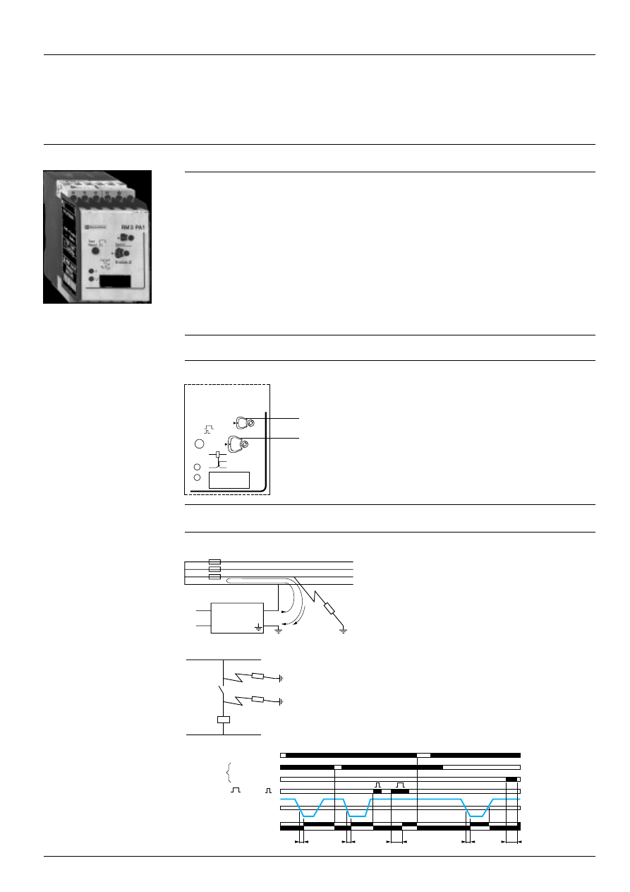
Insulation control relays for a.c. circuits, RM3-PA101
General
Functions
This device monitors the presence of an insulation resistance on an a.c. circuit (with neutral insulated from earth) and
the earth connection.
Its detection threshold range is 1 to 110 k .
A fault memory is possible (automatic or manual, local or remote reset), see page 28312/6 “Setting-up”.
A pushbutton on the front face of the relay allows an “earth fault” TEST to be performed. This test can also be performed
remotely. The LEDs on the front of the relay indicate the various states, see page 28312/6 “Setting-up”.
Applications on a.c. supply
3-phase supplies :
- without neutral conductor,
- with artificial neutral,
- with insulated neutral.
Single-phase supplies :
- control circuit of automation equipment,
- control circuit,
- any auxiliary control circuit galvanically isolated from the mains supply.
Presentation
Width 45 mm
1
Resistance range selector (maximum value in the range, in
k ).
2
End of resistance range setting (from 1 to 11 or from 10 to
110 k ).
F Red LED : indicates a fault.
U Green LED : indicates that supply to the RM3 is on.
Operating principle
The supply voltage is connected to terminals A1-A2 or A1-B2. Its value can be identical to that of the circuit to be monitored.
A continuous voltage (terminal L) is connected between one
phase (or neutral if present) of the installation and earth (
s
terminal).
As soon as an earth insulation fault occurs, it causes a non
infinite resistance to appear between the installation and earth.
A fault current is established and this current then passes
through the so-called “insulation” resistance.
When this current exceeds a value corresponding to the preset
threshold resistance, the output relay is energised with a time
delay (see curve, page 28312/6 “Setting-up”) and a fault
indicator illuminates on the relay.
Purpose of continuous insulation monitor RM3-PA1
The main purpose of this device is to indicate the first insulation
fault in an installation in order to protect it against incorrect
operation due to the appearance of a second fault.
In the diagram opposite, resistances R1 and R2, correspond-
ing to two successive insulation faults, are in series and can
keep K2 energised when contact K1 is open. This incorrect
operation can have very serious consequences in some instal-
lations.
t : time delay, T : time delay Test > 1.5 s.
RM3-PA101
Characteristics :
page 28301/4
References :
page 28312/5
Scheme, dimensions :
page 28312/6
Functional diagram
On RM3 Test
Reset
15-18
15-16
U supply A1-A2/B2
Reset S1/S2
Test S1/
s
Remote
Insulation resistance
Relay
15
18
16
A2
A1
F
U
RM3 PA1
Te
2
1
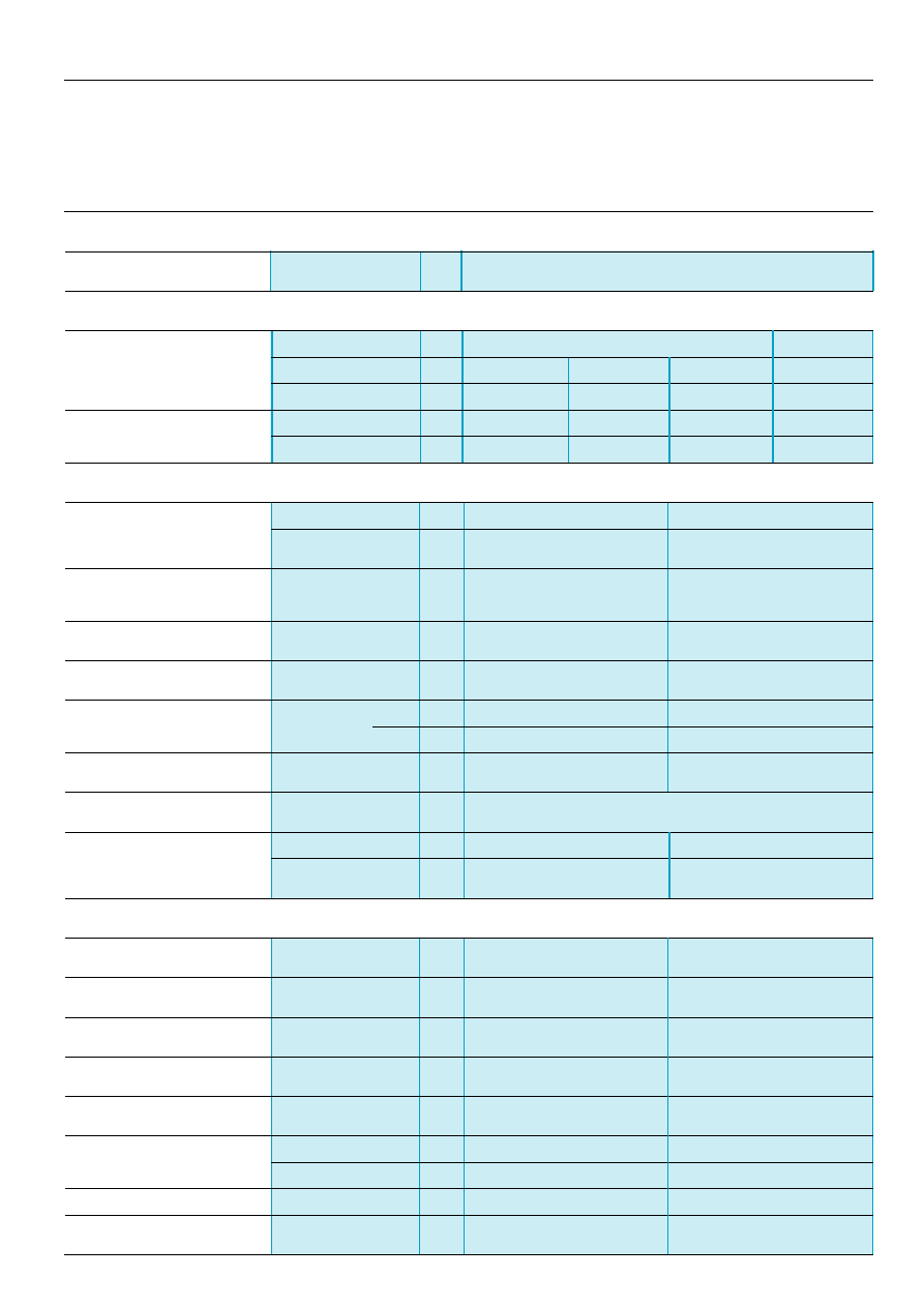
2 8 3 1 2 / 4
Te
Protection components
Measurement and control relays
Insulation control relays RM3-PA1
Characteristics
Environment
Conforming to standards
RM3-PA101
UTE 63080, DIN 0413 (part 2), VDE 0413 part 2
Supply circuit characteristics
RM3-PA101
RM3-PA102
Rated supply voltage (Un)
c
50-60 Hz
V
24...240
110...130
220...240
24...240
a
V
24...240
–
–
24...240
Average consumption at Un
c
VA
4.5
2.5
2.5
5.5
a
W
4.5
–
–
5.5
Output relay and operating characteristics
RM3-PA101
RM3-PA102
Number of C/O contacts
1
1
Output relay state
Energised on detection of an
Energised or de-energised on
insulation fault
detection of an insulation fault,
depending on position of switch
Rated operational voltage
V
400
400
(switching)
Conventional thermal current
A
6
6
Rated breaking capacity
AC-15
250 V
A
3
3
400 V
A
2
2
Time delay
Delay on fault
See curve, page 28312/6
< 1 s for R measured < 0.9 R set
Relay resetting threshold
Fixed setting
Approximately equal to 1.6 times the insulation resistance value set
(tripping of relay)
Operating status indication
U Green LED on
Supply to device on
Supply to device on
F Red LED on
Relay energised on detection of fault
L+ : L+
s
fault
L- : L-
s
fault
Measuring input characteristics
Current of circuit to be monitored
a.c. 50/60 Hz
d.c.
Voltage of circuit to be monitored
Between L+ and L-
V
–
20.4...264
Setting range
k
1...11, 10...110
10...110
Minimum internal resistance
c
or
a
k
100
57
Internal test resistance
820
–
Maximum insulation voltage
Between L and
s
V
415
–
Between L+ and
s
, L- and
s
V
–
300
Measurement voltage
a
V
30 maximum
–
Maximum length of
m
10
10
Test or Reset cable
General :
pages 28312/2 and 28312/3
References :
page 28312/5
Scheme, dimensions :
pages 28312/6 and 28312/7
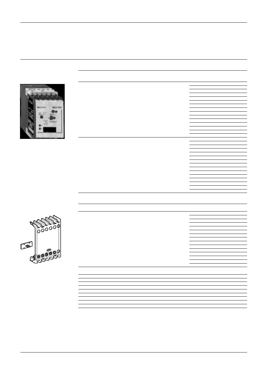
2 8 3 1 2 / 5
Te
Protection components
Measurement and control relays
Insulation control relays RM3-PA1
References
Insulation control relays
Insulation
Current of
Basic reference.
Weight
measurement
monitored
Complete with code indicating
circuit
control circuit voltage (1)
kg
1...110 k
c
c
c
c
RM3-PA101
iii
0.250
10...110 k
a
a
a
a
RM3-PA102
iii
0.210
Accessory
(to be ordered separately)
Description
Reference
Weight
kg
Sealing cover
LA9-RM301
0.005
width 45 mm
(1) Standard supply voltages
RM3-PA101
Volts
24...240
110...130 or 220...240
c
50/60 Hz
MW
FU7
a
MW
–
RM3-PA102
Volts
24...240
c
50/60 Hz
MW
a
MW
RM3-PA101
LA9-RM301
General :
pages 28312/2 and 28312/3
Characteristics :
page 28312/4
Scheme, dimensions :
pages 28312/6 and 28312/7
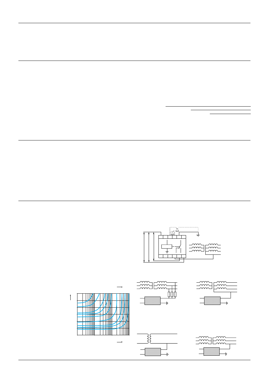
2 8 3 1 2 / 6
Te
0,1
1
10
R
im
100
k
Ω
1,5
1
0,5
2
2,5
t
A
3
Sec
1
2
4 6 10 20
R
is
40 60 100
k
Ω
c
A2
A1
L
RM3-PA1
s
L1
L2
L3
S
P
S
P
c
A2
A1
L
RM3-PA1
s
L1
L2
L3
N
18
15
16
L
A1 15 S1
s
S2
16 18
L
A2
B2
R <
s
S
P
220…240 V
c
/
a
(FU)
110…130 V
c
/
a
(FU)
c
A2
A1
L
RM3-PA1
s
L1
L2
L3
N
S
P
c
A2
A1
L
RM3-PA1
s
L1
L2
L3
S
P
Protection components
Measurement and control relays
Insulation control relays for a.c. circuits, RM3-PA101
Scheme, dimensions, setting-up
Scheme, connection
RM3-PA101
Supply voltages :
Mixed
c
or
a
A1-A2
24...240 V
Dual voltage
c
A1-B2
110...130 V
A1-A2
220...240 V
L,
s
Insulation measurement
(see table opposite)
S1-
s
Remote TEST
S1-S2
Remote Reset
15-18
C/O contact of output
15-16
relay
Dimensions
Setting-up
Fault memory
Short-circuiting of terminals S1 and S2 (see scheme opposite) allows the fault
to be memorised as soon as it appears, even if only fleetingly. The duration of
the fault must exceed the response time of the relay (see curve below) for it to
be detected. If this short-circuiting is achieved by means of a N/C pushbutton,
this acts as the remote reset button (if the fault has disappeared). Manual local
resetting is achieved by briefly pressing (less than 0.5 s) the RESET/TEST
button on the front of the relay.
Test
When the installation being controlled does not have an insulation fault,
pressing the RESET/TEST button on the front of the relay and holding for more
than 1.5 s causes 2 simultaneous actions :
- the measuring input terminal not connected to earth (L) is disconnected from
the line being controlled,
- a resistance (internal) of 820 is connected to this input in order to simulate
an insulation fault.
The relay must then react in the same way as for a real fault.
A N/O pushbutton may be connected to terminals S1 and
s
which will act as the
remote test button and this will have the same effect as the built-in test button
(see scheme opposite).
t
A
= Delay on energisation
R
im
= Insulation resistance measured
R
is
= Insulation resistance threshold
Connection and values of the 2 resistance ranges to be
controlled
RM3-PA101
L to
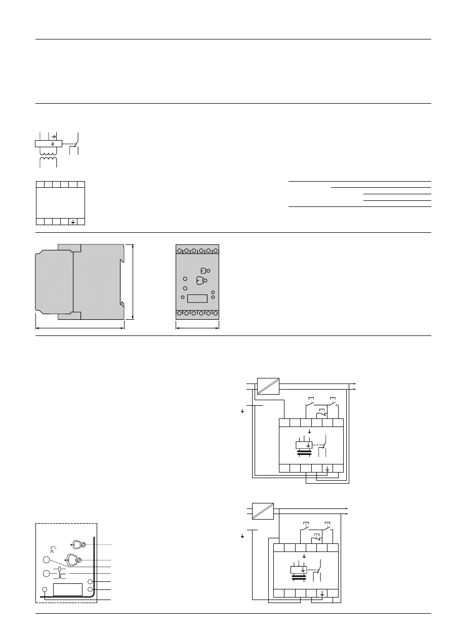
2 8 3 1 2 / 7
Te
Protection components
Measurement and control relays
Insulation control relays for d.c. circuits, RM3-PA102
Scheme, dimensions, setting-up
Scheme, connection
RM3-PA102
Supply voltages :
Mixed
c
or
a
A1-A2
24...240 V
L+, L-
s
Insulation measurement
(see table opposite)
S1-S3
Remote TEST, L+
S3-S4
Remote TEST, L-
S2-S3
Remote Reset
15-18
C/O contact of output
15-16
relay
Dimensions
Setting-up
Fault memory
Short-circuiting of terminals S3 and S2 allows the fault to be memorised as soon
as it appears, even if only fleetingly. If this short-circuiting is achieved by means
of a N/C pushbutton, this acts as the remote reset button (if the fault has
disappeared). Manual local resetting is achieved by briefly pressing (less than
1 s) the RESET/TEST button on the front face of the relay.
Test
When the installation being controlled does not have an insulation fault, the two
control circuits, corresponding to each polarity, can be tested independently.
Testing circuit L+
s
Pressing button
3
on the front of the relay and holding for more than 1 s causes
2 simultaneous actions :
- the measuring input terminal L+ is disconnected from the line being controlled,
- an internal resistance is connected to this input in order to simulate an
insulation fault.
The relay must then react in the same way as for a real fault.
Testing circuit L-
s
Pressing button
4
on the front of the relay causes 2 simultaneous actions :
- the measuring input terminal L- is disconnected from the line being controlled,
- an internal resistance is connected to this input in order to simulate an
insulation fault.
The relay must then react in the same way as for a real fault.
Connection and values of the resistance ranges to be
controlled
RM3-PA102
L+ to
s
10…110 k
L- to
s
Basic scheme of the installation
- Separate supply to RM3
- Supply to RM3 from circuit being monitored
18
15
16
A2
L
–
L
+
A1
R <
A1 15 S1 S2 S3 S4
16 18
A2
L-
L+
L
L+
L-
N
PE
( )
24-240 V AC
24-240 V DC
AC
DC
A1
A2
18
15
L+L-
16
R <
Reset
Test +
Test -
A1
15
S1
S2
S3
S4
16
18
L+
L-
A2
L
L+
L-
N
PE
( )
24-240 V DC
AC
DC
A1
A2
18
15
L+L-
16
R <
Reset
Test +
Test -
A1
15
S1
S2
S3
S4
16
18
L+
L-
A2
15
18
16
A2
A1
U
F
2
6
7
4
3
5
1
Test
Reset
Test
Te
General :
page 28312/3
Characteristics :
page 28312/4
References :
page 28312/5
45
77,5
100
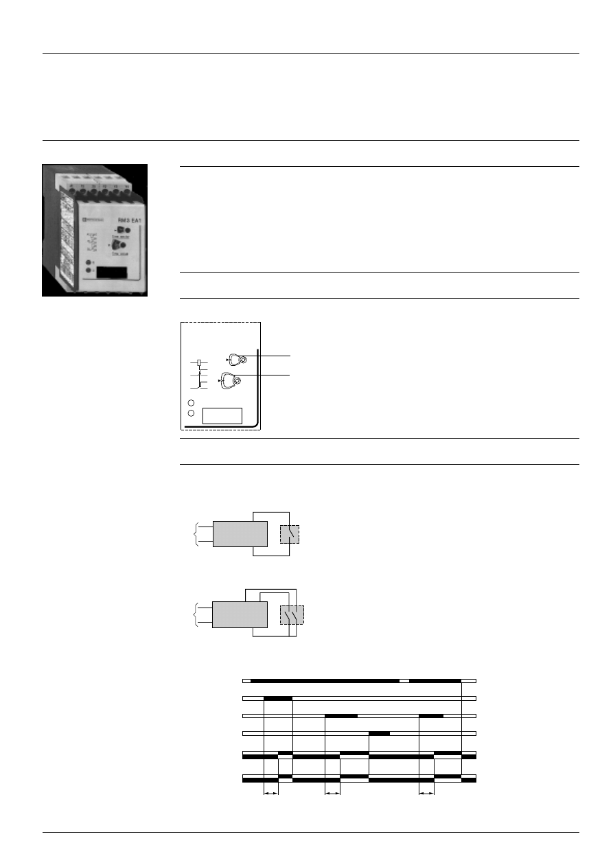
28313/2
Te
15
18
16
A2
A1
25
28
26
R
U
RM3 EA1
Te
2
1
Protection components
Measurement and control relays
Sensitive contact protection relays RM3-EA1
General
Functions
This device relays, protects and amplifies a low level “Discrete” output. It may be used with or without memory function.
The adjustable time delay from 0.05 to 30 s avoids oscillations of the relay in the event of interference or bouncing of the
contact to be protected.
It can be controlled by a mechanical contact or by a 3-wire solid state switch (see examples, page 28313/5 “Setting-up”).
Applications :
- protection,
- ensuring reliability,
- amplification of low level outputs on measuring devices, sensors, probes etc.
Presentation
Width 45 mm
1
Time delay range selector switch (0.05 to 1 s and 1.5 to
30 s).
2
End of time delay setting.
R Yellow LED : indicates relay state.
U Green LED : indicates that supply to the RM3 is on.
Operating principle
The supply voltage is connected to terminals A1-A2.
Protection of “Discrete” contacts
The RM3’s output relay is energised when terminals Y1-Y2
are connected to the contact to be protected and this
contact is closed.
Protection of contacts with memory (latching)
The RM3’s output relay is energised when terminals Y1-Y3
are connected to the contact to be protected and this
contact is closed for a time 20 ms.
It remains energised after opening of Y1-Y3.
It de-energises when Y1 - Y4 are short-circuited.
Functional diagram
t : time delay
U supply A1/A2
15-18
15-16
t
t
t
25-28
25-26
Y1/Y4
Y1/Y3
Y1/Y2
Relay
Contact to
be protected
Contact to
be protected
A1
RM3-EA
Y4
Y3
Y1
A2
A1
RM3-EA
Y1
Y2
A2
RM3-EA1
Contact
to be
protected
Characteristics :
pages 28301/2, 28301/3 and 28313/3
References :
page 28313/4
Sche
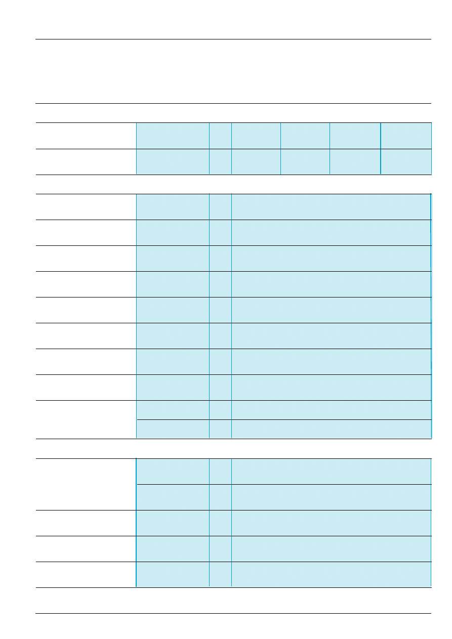
2 8 3 1 3 / 3
Te
General :
page 28313/2
References :
page 28313/4
Scheme, dimensions :
page 28313/5
Protection components
Measurement and control relays
Sensitive contact protection relays RM3-EA1
Characteristics
Supply circuit characteristics
Rated supply voltage (Un)
c
50-60 Hz
V
24
110...130
220...240
380...415
Average consumption at Un
c
VA
3.4
3.4
3.4
3.4
Output relay and operating characteristics
Number of C/O contacts
2
Output relay state
See diagram page 28313/2 and note (1) below
Rated operational voltage
V
400
(switching)
Conventional thermal current
A
5
Rated breaking capacity
AC-15
230 V-3 A, 400 V-2 A
Time delay on energisation
Adjustable
s
0.05...30
Time delay on de-energisation
ms
50
Minimum closing time for
ms
20
memory (latching)
Operating status indication
U Green LED on
Supply to device on
R Yellow LED on
Relay energised
Measuring input characteristics
Resistance
Energisation guaranteed
“Discrete” contacts Y1-Y2 < 6.5 k
“Latching” contacts Y1-Y3 < 6.5 k
De-energisation guaranteed
“Discrete” contacts Y1-Y2 > 19 k
“Latching” contacts Y1-Y4 < 16 k
No-load voltage
a
current
V
10
Switching current
mA
3
Continuous voltage applied
3-wire control,
V
30
(maximum)
a
current
(1) If circuits Y1-Y3 and Y1-Y4 are closed, the output relay is energised.
The relay memory is reset to zero when the power supply is switched off.
In the event of a power failure, the relay de-energises and is re-energised at switch-on only if circuit Y1-Y3 is closed.
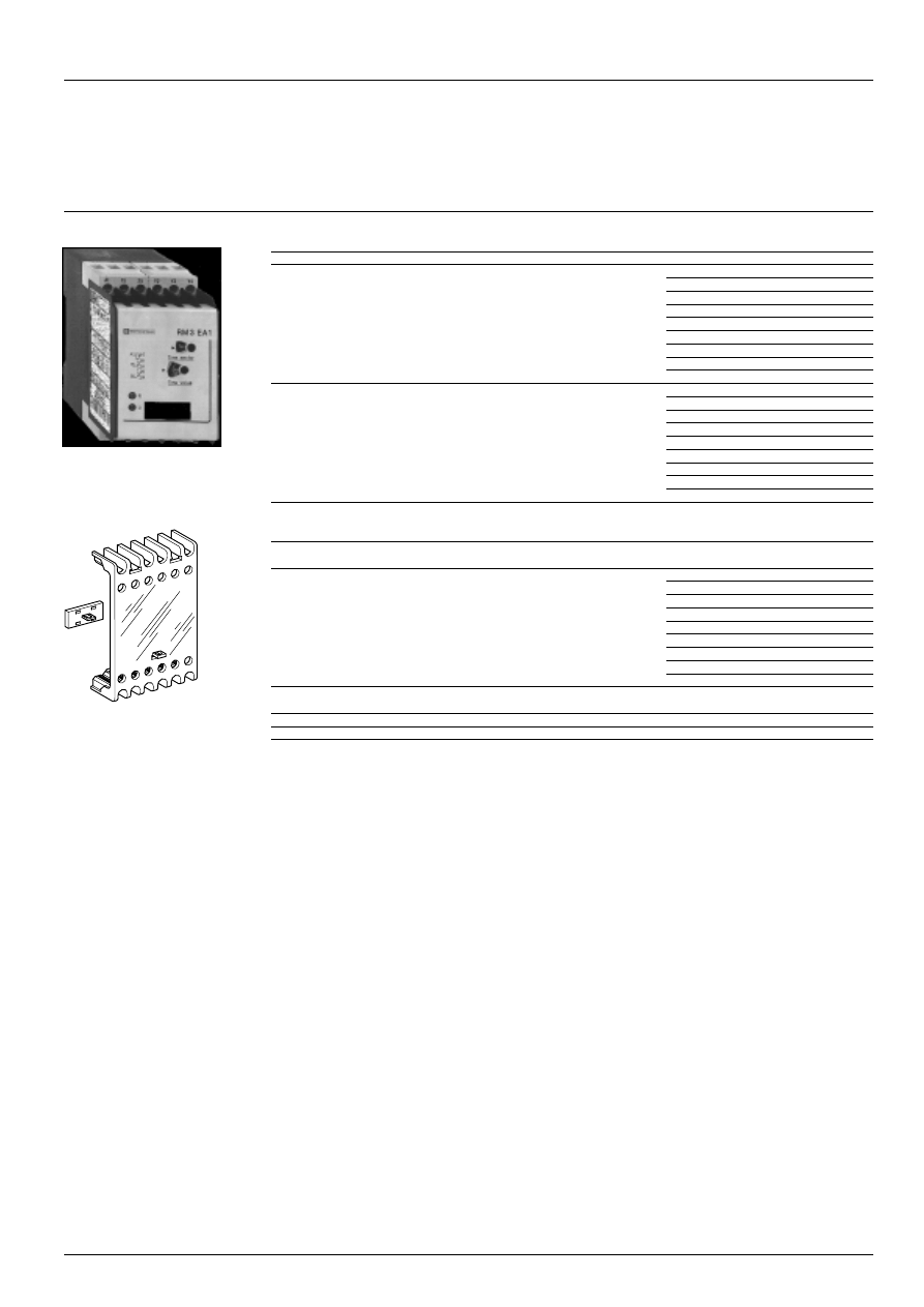
2 8 3 1 3 / 4
Te
Protection components
Measurement and control relays
Sensitive contact protection relays RM3-EA1
References
Time delay
Basic reference. Complete
Weight
with code indicating
control circuit voltage (1)
s
kg
Adjustable
RM3-EA111
iii
0.310
0.05...30
None
RM3-EA101
iii
0.310
Accessory
(to be ordered separately)
Description
Reference
Weight
kg
Sealing cover
LA9-RM301
0.005
width 45 mm
(1) Standard supply voltages
Volts
24
110...130
220...240
380...415
c
50/60 Hz
B7
FG7
MU7
QN7
RM3-EA1
LA9-RM301
General :
page 28313/2
Characteristics :
pages 28301/2, 28301/3 and 28313/3
Scheme, dimensions :
page 28313/5
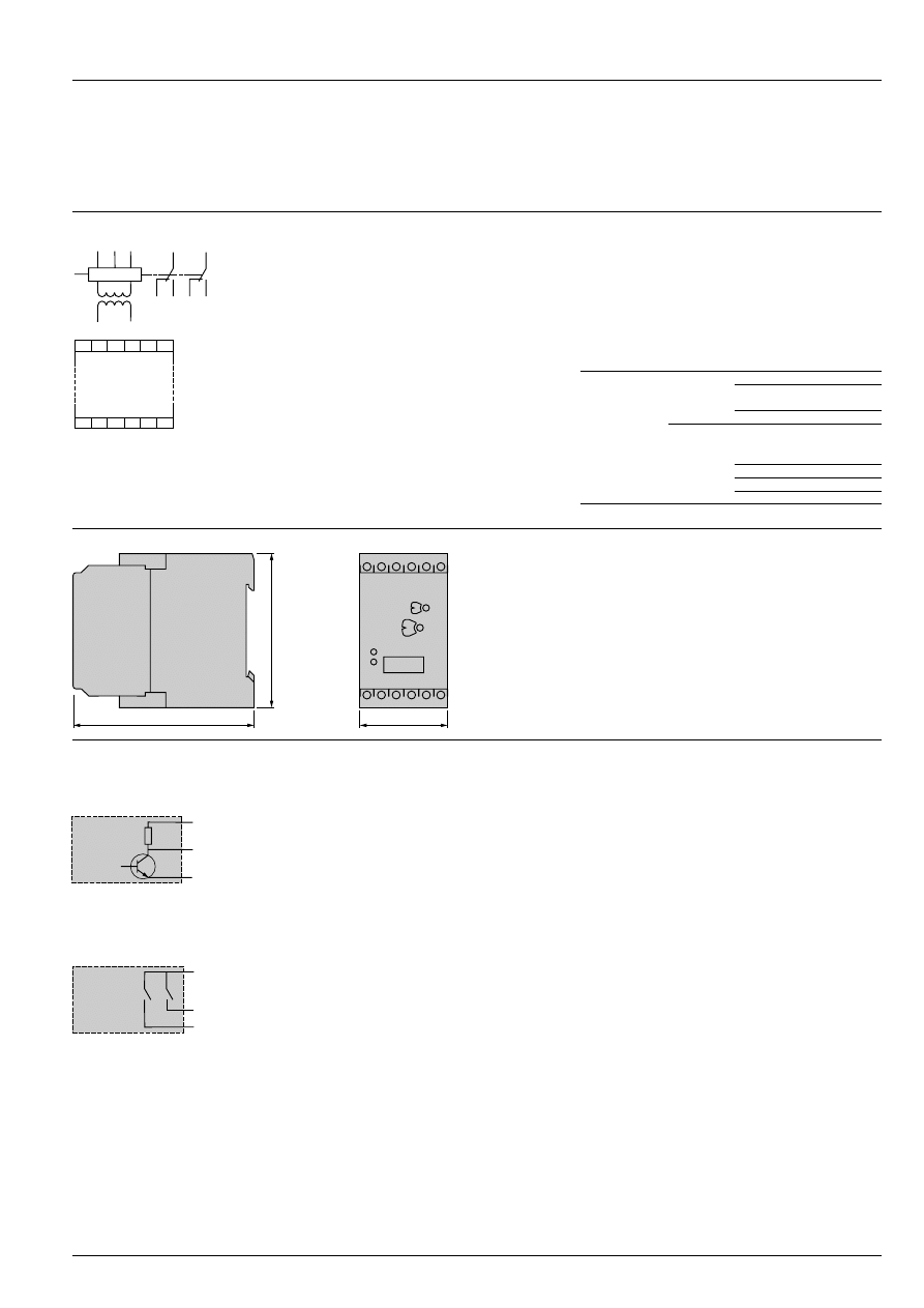
28313/5
Te
Protection components
Measurement and control relays
Sensitive contact protection relays RM3-EA1
Scheme, dimensions, setting-up
Scheme, connection
RM3-EA1
A1-A2
Supply voltage
Y1, Y2,
Connection of contacts to be
Y3, Y4
monitored (see table opposite)
15-18
1
st
C/O contact of output relay
15-16
25-28
2
nd
C/O contact of output relay
25-26
Dimensions
Setting-up
Energisation by 3-wire NPN solid state switch
On : the relay is energised (Y1-Y3).
Off : the relay is de-energised (Y1-Y4).
Relays having two contacts with common point may be connected to two separate RM3-EA1 relays.
The common point of the contacts must be connected to terminal Y2 of each RM3-EA1.
Connection and type of protection
RM3-EA1
i
1
Y1-Y2
Protection of “Discrete”
contact
Protection of contact with
memory “Latching” :
Y1-Y3
Energisation
Y1-Y4
De-energisation
NPN
+
UB
Y1
Y3/
–
UB
Y4/
–
UB
18
15
16
Y4
28
25
26
Y3
Y2
A2
A1
Y1
A1 15 25
Y3 Y4
Y2
16 18 28
Y1 A2
26
General :
page 28313/2
Characteristics :
pages 28301/2, 28301/3 and 28313/3
References :
page 28313/4
45
77,5
100
Y2
(RM3-EA N°1)
(RM3-EA N°2)
Y1 (RM3-EA N°2)
Y1 (RM3-EA N°1)
Document Outline
- Protection components
- Zelio Control measurement and control relays
- General characteristics
- Current measurement relays RM4-JA
- Voltage measurement relays RM4-UA
- 3-phase supply control relays RM4-T
- Single-phase supply control relays RM4-UB
- Liquid level control relays
- Insulation control relays for a.c. circuits, RM3-PA101
- Insulation control relays RM3-PA1
- Insulation control relays for a.c. circuits, RM3-PA101
- Insulation control relays for d.c. circuits, RM3-PA102
- Sensitive contact protection relays RM3-EA1
Wyszukiwarka
Podobne podstrony:
02 ZELIO TIME CATALOGUE
04 1b Zelio Control RM4T instr Nieznany
04 1b Zelio Control RM4U RM4J i Nieznany (2)
04 1b Zelio Control RM4L instr uzytk
controlling finansowy - ćwiczenia 1 - 02.10.2011
04 1a ZELIO TIME CONTROL PANORA Nieznany (2)
02 PHASEO POWER SUPPLIES CATALOGUE
2013 Ankieta 1 bez controllingu 15 02 2013id 28299
2013 Ankieta 1 bez controllingu 15 02 2013
Raport Karma Royal Canin Vet Diet Sensitive Control Ocena 02 na 20
więcej podobnych podstron