WS13-1
PAT301, Workshop 13, December 2005
Copyright 2005 MSC.Software Corporation
WORKSHOP 13
CANTILEVERED BEAM USING 1D OR
2D ELEMENTS, AND ANALYSIS
MES w modelowaniu układów mechatronicznych lab. 1,2 (based on MSC tutorial WS13

WS13-2
PAT301, Workshop 13, December 2005
Copyright 2005 MSC.Software Corporation
MES w modelowaniu układów mechatronicznych lab. 1,2 (based on MSC tutorial WS13

WS13-3
PAT301, Workshop 13, December 2005
Copyright 2005 MSC.Software Corporation
Workshop Objectives
Create two models of a cantilevered beam. The models are for
1D (bar elements) or 2D (plate elements). Compare the results
from the analysis for the models.
Problem Description
Compare the deformation and stress results for the two types of
models.
Piston material: Aluminum with E = 2e5 MPa and ! = 0.3
Force on tip of beams = 150 N
Software Version
MSC.Patran 2005r2
MSC.Nastran 2005r2b
MES w modelowaniu układów mechatronicznych lab. 1,2 (based on MSC tutorial WS13

WS13-4
PAT301, Workshop 13, December 2005
Copyright 2005 MSC.Software Corporation
Key Concepts and Steps:
Database: create a database with Analysis Code = MSC.Nastran and
Analysis Type = Structural
Geometry: create a 50mm x 10mm x 15mm parametric solid
Elements: create 2D Quad4 mesh on the four long sided faces of the solid
Loads/BCs: apply concentrated force at free end of cantilevered beam.
Constrain cantilevered end of beam.
Materials: create material properties for beam; use aluminum properties.
Properties: create properties for Quad4 elements. They include both
bending and membrane properties.
Analysis: Solution Type = Nastran Linear Static, Solution Sequence =
101, Method = Full Run
Analysis: access analysis results by attaching the XDB file to database
Results: view both the deformation and stress results
MES w modelowaniu układów mechatronicznych lab. 1,2 (based on MSC tutorial WS13

WS13-5
PAT301, Workshop 13, December 2005
Copyright 2005 MSC.Software Corporation
Key Concepts and Steps: (continued)
Database: create a database with Analysis Code = MSC.Nastran and
Analysis Type = Structural
Geometry: create a <50 0 0> curve
Elements: mesh the curve with 1D Bar2 elements. Create a rigid link
(MPC) for force application at the free end of the cantilevered beam.
Loads/BCs: apply a concentrated force at the free end of the MPC
Materials: create material properties for beam; use aluminum properties.
Properties: create properties for Bar2 elements. Use the Beam Library
and select the rectangular cross-section option.
Analysis: Solution Type = Nastran Linear Static, Solution Sequence =
101, Method = Full Run
Analysis: access analysis results by attaching the XDB file to database
Results: view both the deformation and stress results
Results: compare the 2D and 1D model results
MES w modelowaniu układów mechatronicznych lab. 1,2 (based on MSC tutorial WS13
WS13-6
PAT301, Workshop 13, December 2005
Copyright 2005 MSC.Software Corporation
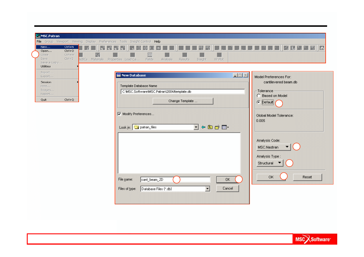
Step 1. Create a Database for 2D Element Model
Create a new database for 2D
element model.
a.
File / New.
b.
Enter cant_beam_2D as
the file name.
c.
Click OK.
d.
Choose Default Tolerance.
e.
Select MSC.Nastran as the
Analysis Code.
f.
Select Structural as the
Analysis Type.
g.
Click OK.
a
b
e
f
d
c
g
MES w modelowaniu układów mechatronicznych lab. 1,2 (based on MSC tutorial WS13
WS13-7
PAT301, Workshop 13, December 2005
Copyright 2005 MSC.Software Corporation
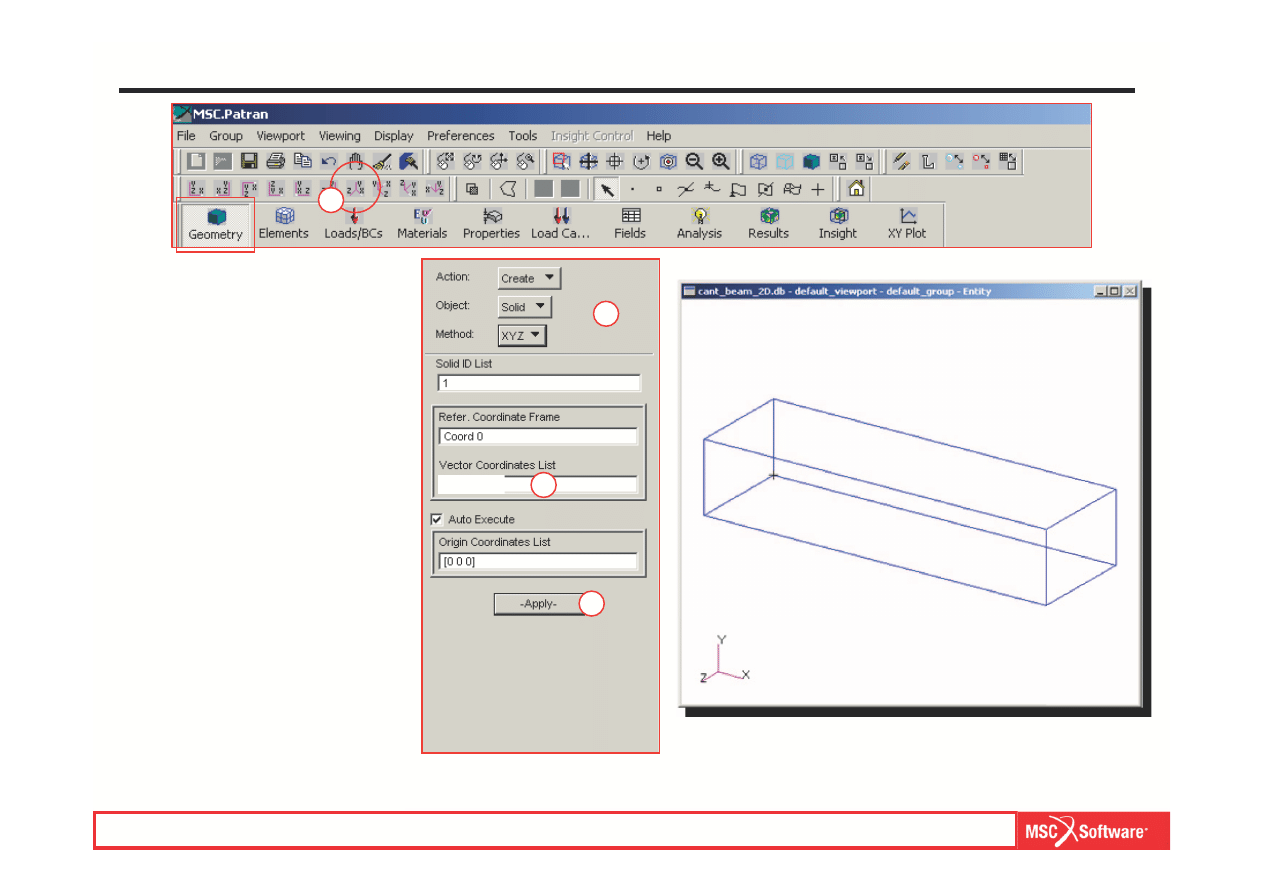
Step 2. Create Solid Geometry
a.
Geometry: Create / Solid /
XYZ.
b.
Select on Vector
Coordinates List and enter
< 50 10 15 >.
c.
Apply.
d.
Change view to I
so 1 View.
a
b
c
d
MES w modelowaniu układów mechatronicznych lab. 1,2 (based on MSC tutorial WS13
< 50 10 15 >
WS13-8
PAT301, Workshop 13, December 2005
Copyright 2005 MSC.Software Corporation
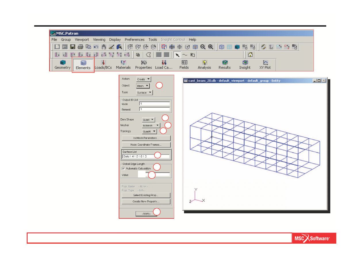
Step 3. Create 2D Element Mesh
a.
Elements: Create / Mesh /
Surface.
b.
Element Shape: Quad.
c.
Mesher: I
soMesh.
d.
Topology: Quad4.
e.
Click on Surface List and
select the four long faces of
the solid, not including the
end faces.
f.
Uncheck Automatic
Calculation.
g.
Enter 5 for Global Edge
Length.
h.
Apply.
a
g
h
f
e
b
c
d
MES w modelowaniu układów mechatronicznych lab. 1,2 (based on MSC tutorial WS13
5
WS13-9
PAT301, Workshop 13, December 2005
Copyright 2005 MSC.Software Corporation
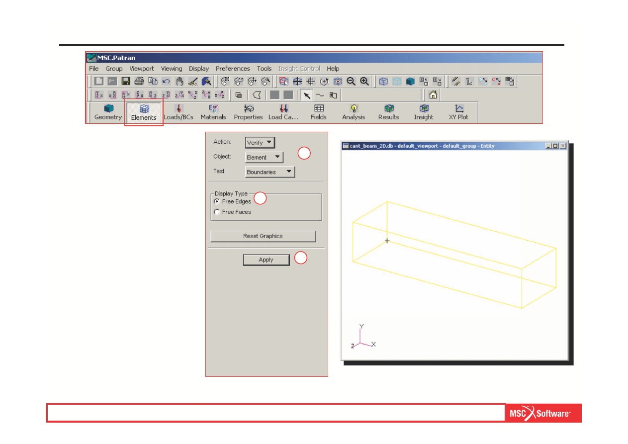
Step 4. Display Free Edges
a.
Elements: Verify / Element /
Boundaries.
b.
Display Type: Free Edges.
c.
Apply.
d.
As shown in the figure,
yellow lines along the solid
edges should appear
a
b
c
MES w modelowaniu układów mechatronicznych lab. 1,2 (based on MSC tutorial WS13
WS13-10
PAT301, Workshop 13, December 2005
Copyright 2005 MSC.Software Corporation
b
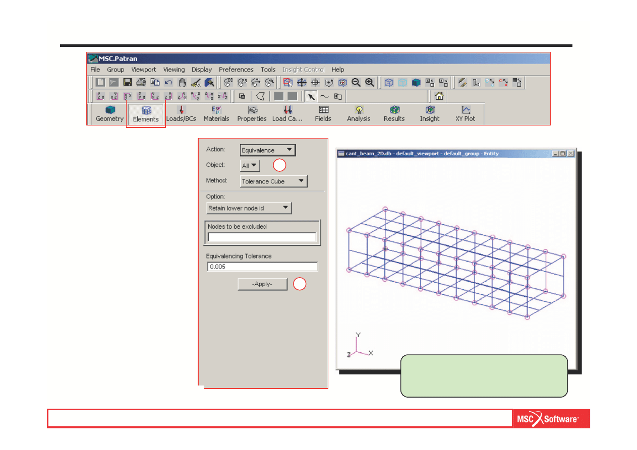
Step 5. Connect the Elements Together
a.
Elements: Equivalence / All /
Tolerance Cube.
b.
Apply.
Notice that magenta colored circles
are drawn where nodes are
equivalenced.
a
MES w modelowaniu układów mechatronicznych lab. 1,2 (based on MSC tutorial WS13
WS13-11
PAT301, Workshop 13, December 2005
Copyright 2005 MSC.Software Corporation
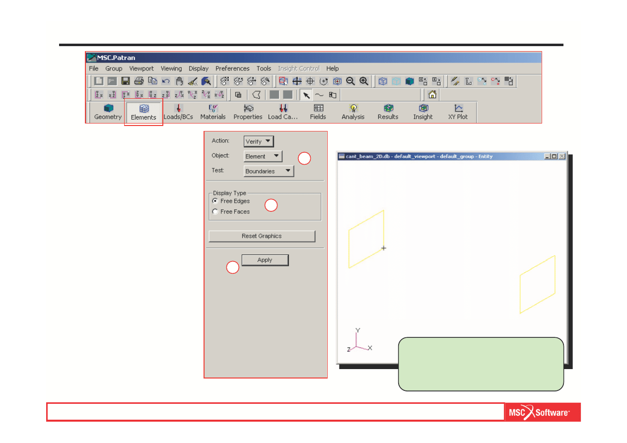
Step 6. Display Free Edges Again
a.
Elements: Verify / Element /
Boundaries.
b.
Display Type: Free Edges.
c.
Apply.
No longer do the yellow lines in the
long direction appear. This means
that the adjacent 2D quad elements
are connected.
a
b
c
MES w modelowaniu układów mechatronicznych lab. 1,2 (based on MSC tutorial WS13
WS13-12
PAT301, Workshop 13, December 2005
Copyright 2005 MSC.Software Corporation
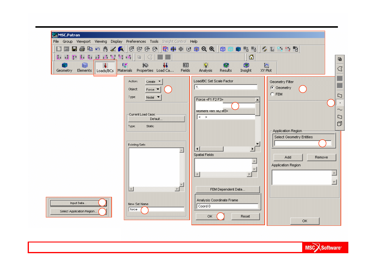
Step 7. Apply a Force at One End
a.
Loads / BCs: Create / Force
/ Nodal.
b.
Select on New Set Name
and enter force.
c.
Input Data.
d.
Enter <
0 -150 0> for Force
<F1 F2 F3 >.
e.
OK.
f.
Select Application Region.
g.
Geometry Filter: Geometry.
h.
Click on Select Geometry
Entities.
i.
Select Point or Vertex icon
from the Pick Menu.
a
b
c
d
e
f
g
h
i
MES w modelowaniu układów mechatronicznych lab. 1,2 (based on MSC tutorial WS13
< 0 -150 0 >
WS13-13
PAT301, Workshop 13, December 2005
Copyright 2005 MSC.Software Corporation
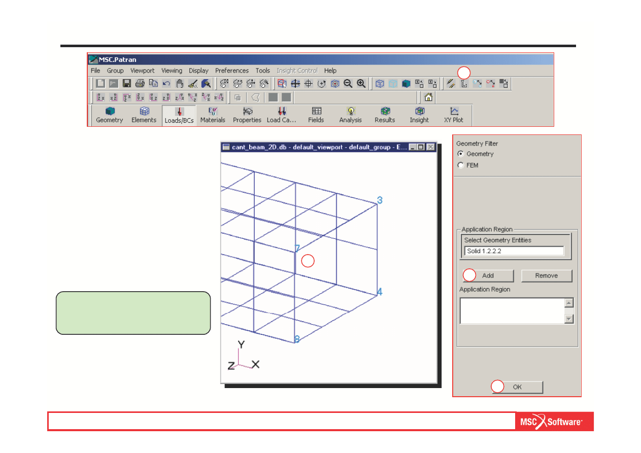
Step 7. Apply a Force at One End (cont.)
a.
Turn on the Point labels.
b.
Select on the point (Point 7)
as shown in the figure.
c.
Add.
d.
OK.
e.
Apply.
Close-Up
b
c
d
a
Note that selecting Point 7 and
Vertex Solid 1.2.2.2 is
equivalent.
MES w modelowaniu układów mechatronicznych lab. 1,2 (based on MSC tutorial WS13
WS13-14
PAT301, Workshop 13, December 2005
Copyright 2005 MSC.Software Corporation
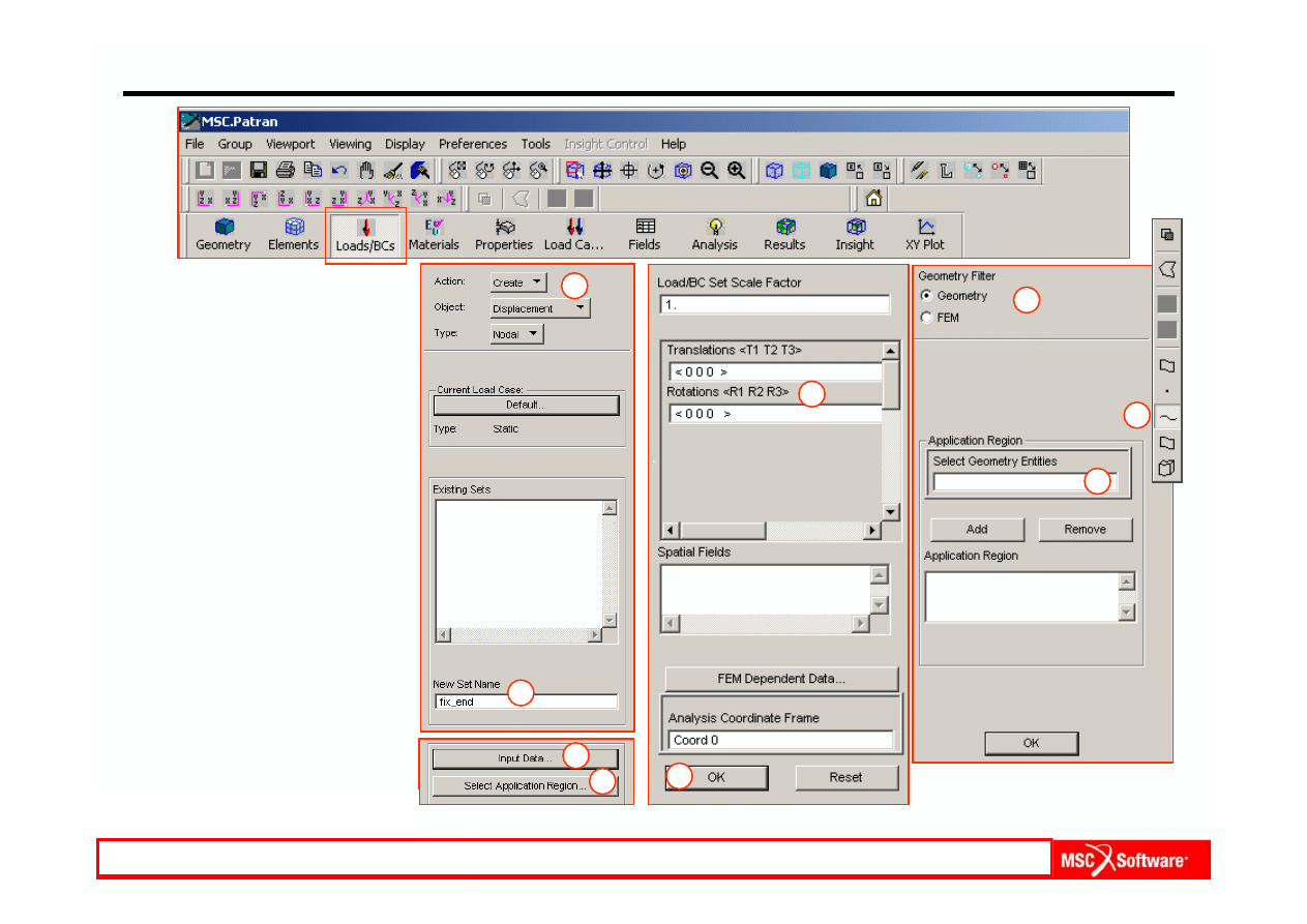
Step 8. Create Constraints
Constrain beam at other end, fixing
all six degrees of freedom at all
nodes.
a.
Loads / BCs: Create /
Displacements / Nodal.
b.
Select on New Set Name:
and enter fix_end.
c.
Select Input Data.
d.
Enter <
0 0 0> for
Translations <T1 T2 T3 >
and Rotations <R1 R2 R3>.
e.
OK.
f.
Click on Select Application
Region.
g.
Select Geometry for
Geometry Filter.
h.
Click on Select Geometry
Entities.
i.
Select Curve or Edge icon
for the picking.
a
b
c
d
e
f
g
h
i
MES w modelowaniu układów mechatronicznych lab. 1,2 (based on MSC tutorial WS13
WS13-15
PAT301, Workshop 13, December 2005
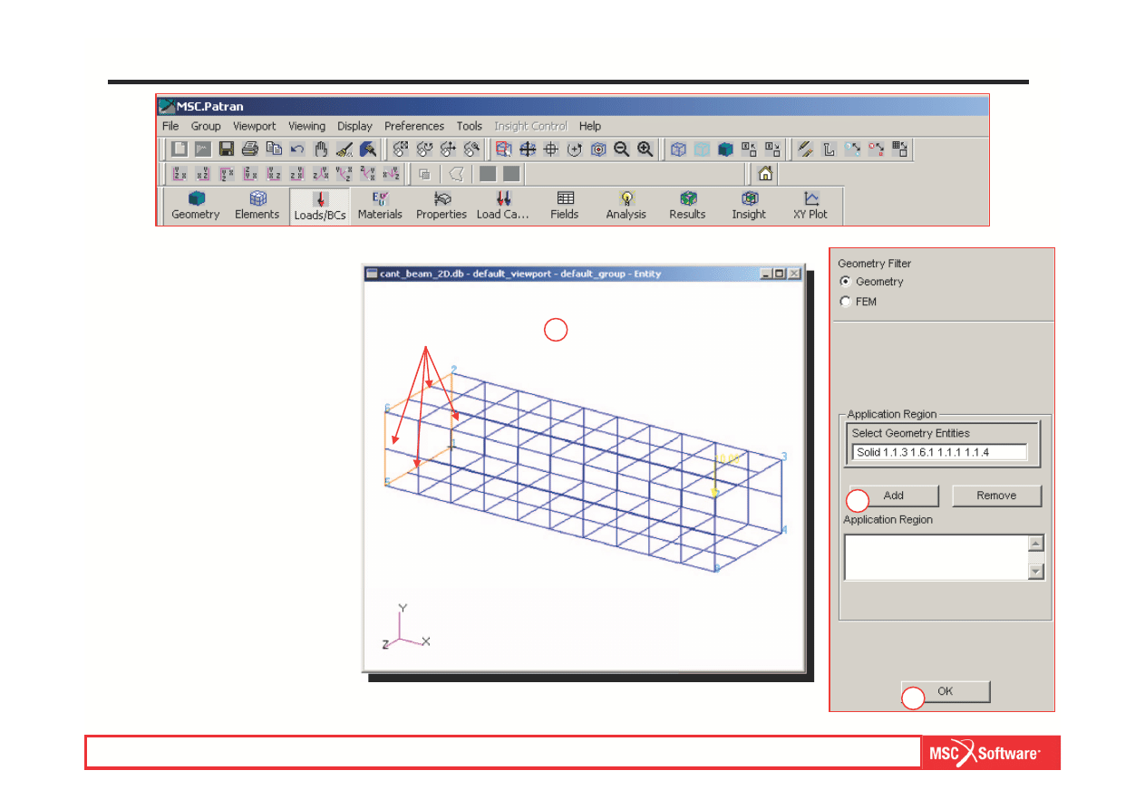
Copyright 2005 MSC.Software Corporation
a.
Select the four solid edges
as shown in the figure.
b.
Add.
c.
OK.
d.
Apply.
Step 8. Create Constraints (Cont.)
Select these edges
a
b
c
MES w modelowaniu układów mechatronicznych lab. 1,2 (based on MSC tutorial WS13
WS13-16
PAT301, Workshop 13, December 2005
Copyright 2005 MSC.Software Corporation
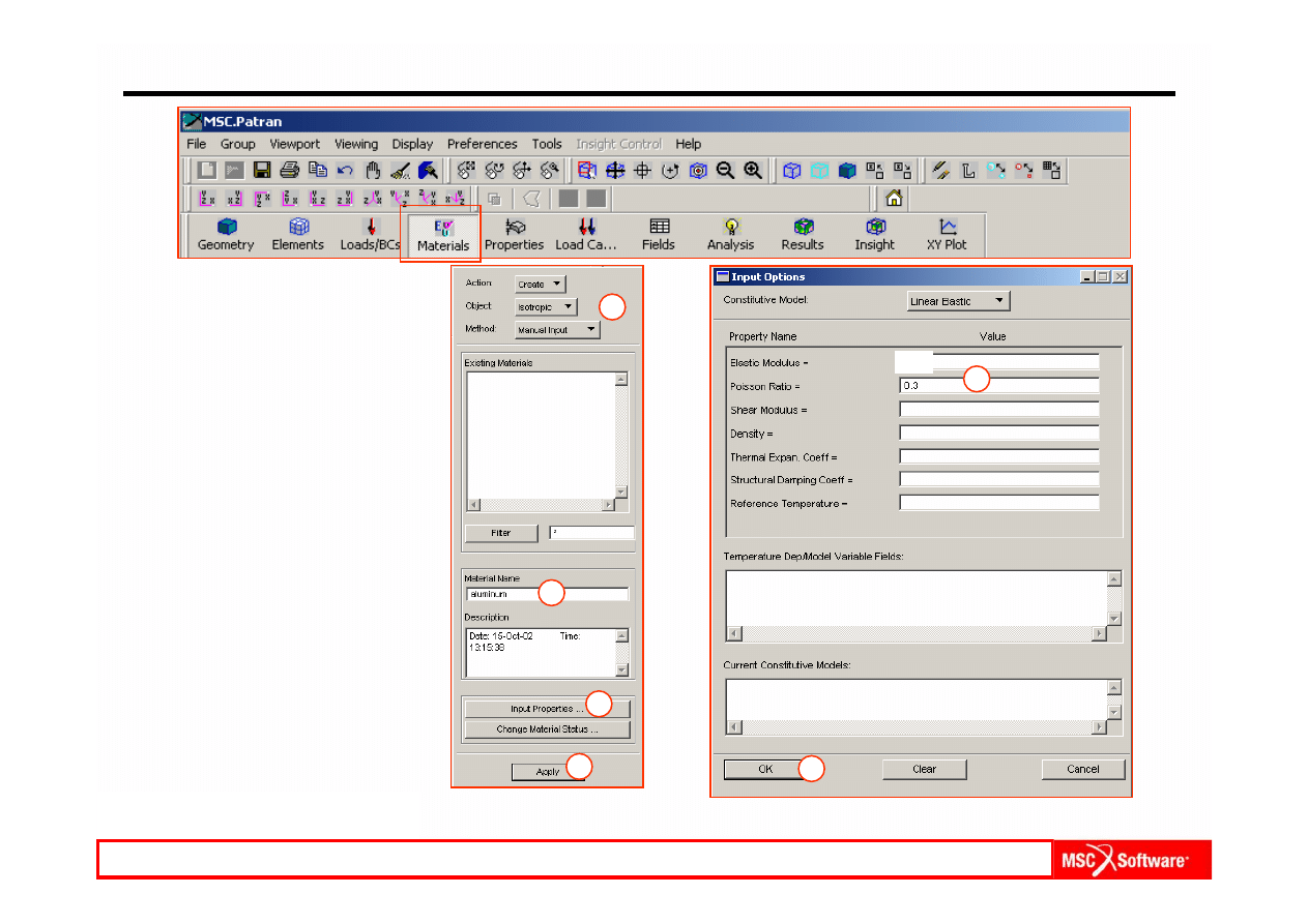
Step 9. Create Material Properties
a.
Materials: Create / Isotropic /
Manual Input.
b.
Select on Material Name
and enter aluminum.
c.
Select I
nput Properties.
d.
Enter:
Elastic Modulus: 2e5.
Poisson Ratio: 0.3.
e.
OK.
f.
Apply.
a
b
c
d
e
f
MES w modelowaniu układów mechatronicznych lab. 1,2 (based on MSC tutorial WS13
2e5
WS13-17
PAT301, Workshop 13, December 2005
Copyright 2005 MSC.Software Corporation
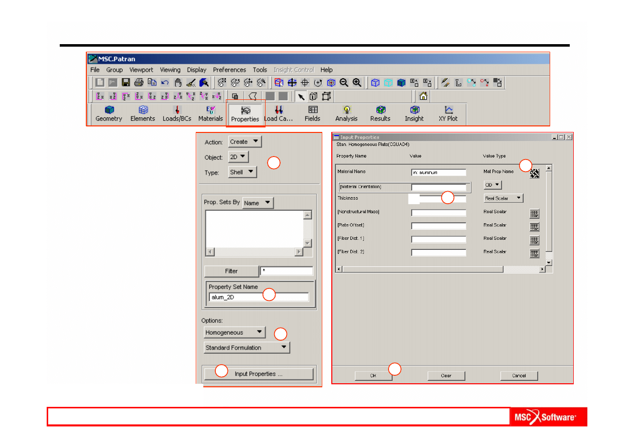
Step 10. Create Element Properties for the 2D Quad Topology
a.
Properties: Create / 2D /
Shell.
b.
Option(s): Homogeneous /
Standard Formulation.
c.
Select Property Set Name
and enter alum_2D.
d.
Select Input Properties.
e.
Click on Mate
rial Property
Name icon and select
aluminum under Select
Existing Material.
f.
Thickness: 1.
g.
OK.
a
b
c
d
e
f
g
MES w modelowaniu układów mechatronicznych lab. 1,2 (based on MSC tutorial WS13
1
WS13-18
PAT301, Workshop 13, December 2005
Copyright 2005 MSC.Software Corporation
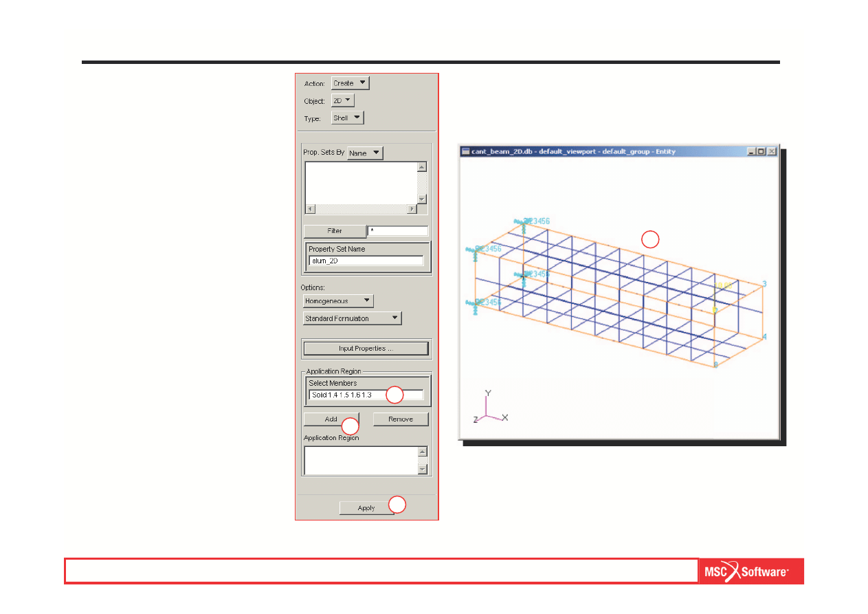
Step 10. Create Element Properties for the 2D Quad Topology (Cont.)
a.
Click on Select Members.
b.
Select the four long solid
faces.
c.
Add.
d.
Apply.
e.
Turn off the Point labels.
a
b
c
d
MES w modelowaniu układów mechatronicznych lab. 1,2 (based on MSC tutorial WS13
WS13-19
PAT301, Workshop 13, December 2005
Copyright 2005 MSC.Software Corporation
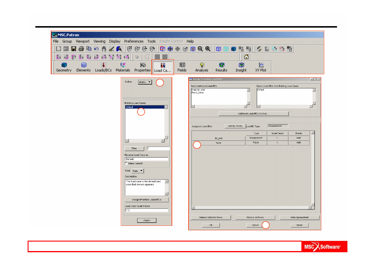
Step 11. Check Assignment of Loads and BC’s to Load Case
a.
Load Cases: Modify.
b.
Select Default in Select
Load Case to Modify.
c.
Check that all Loads and
BC’s are selected.
d.
Cancel.
a
b
c
d
MES w modelowaniu układów mechatronicznych lab. 1,2 (based on MSC tutorial WS13
WS13-20
PAT301, Workshop 13, December 2005
Copyright 2005 MSC.Software Corporation
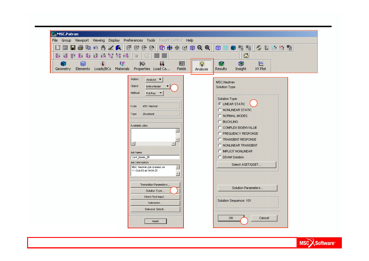
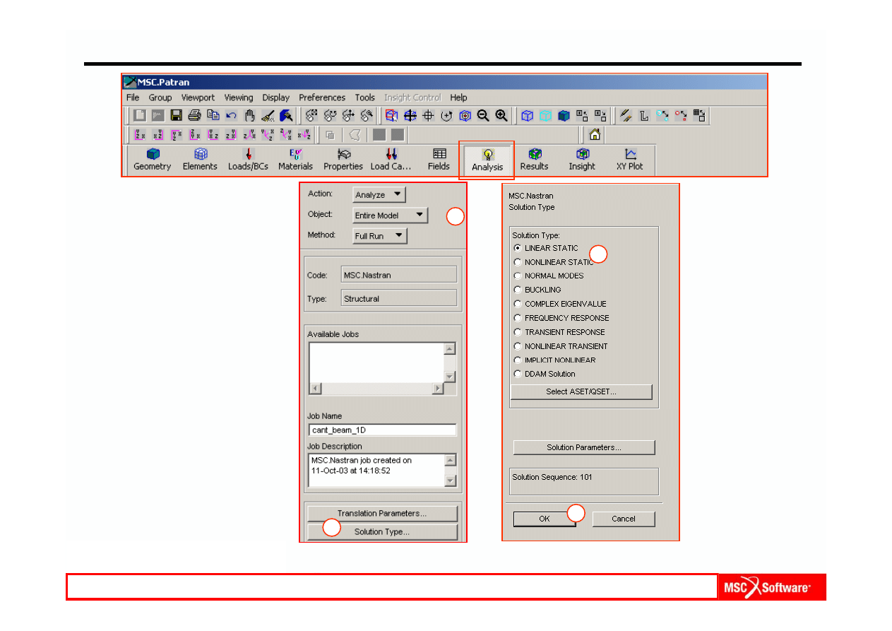
Step 12. Run the Analysis
Run the analysis of the model.
a.
Analysis: Analyze / Entire
Model / Full Run.
b.
Select Solution Type.
c.
Choose L
INEAR STATIC for
Solution Type.
d.
OK.
e.
Apply.
b
c
d
a
MES w modelowaniu układów mechatronicznych lab. 1,2 (based on MSC tutorial WS13
WS13-21
PAT301, Workshop 13, December 2005
Copyright 2005 MSC.Software Corporation
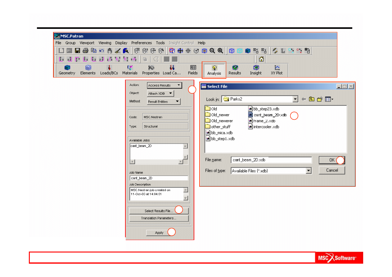
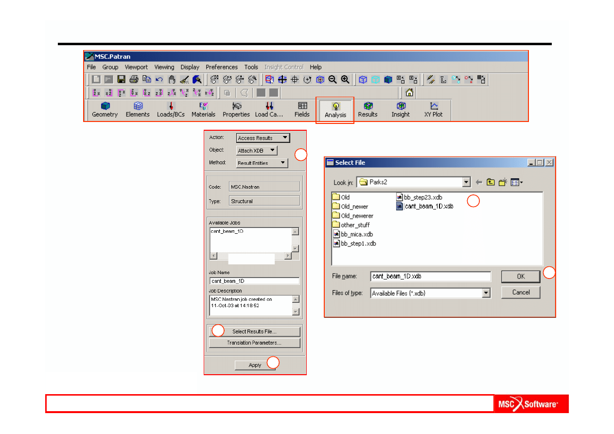
Step 13. Read Results Under Analysis
Attach the .xdb file to read the
results.
a.
Analysis: Access Results /
Attach XDB / Result Entities.
b.
Click on Select Results
File.
c.
Select and attach
cant_beam_2D.xdb.
d.
OK.
e.
Apply.
c
d
a
b
e
MES w modelowaniu układów mechatronicznych lab. 1,2 (based on MSC tutorial WS13
WS13-22
PAT301, Workshop 13, December 2005
Copyright 2005 MSC.Software Corporation
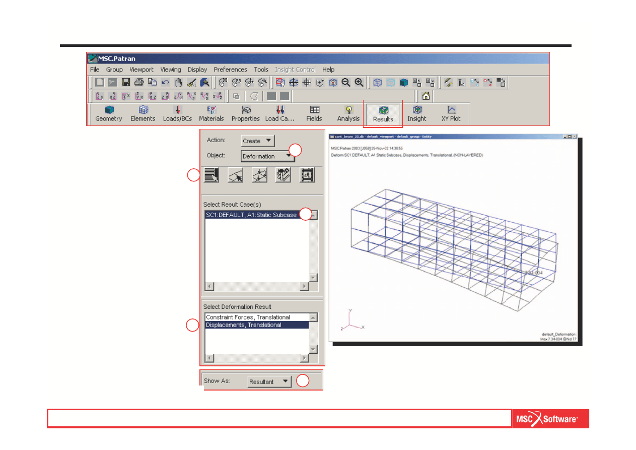
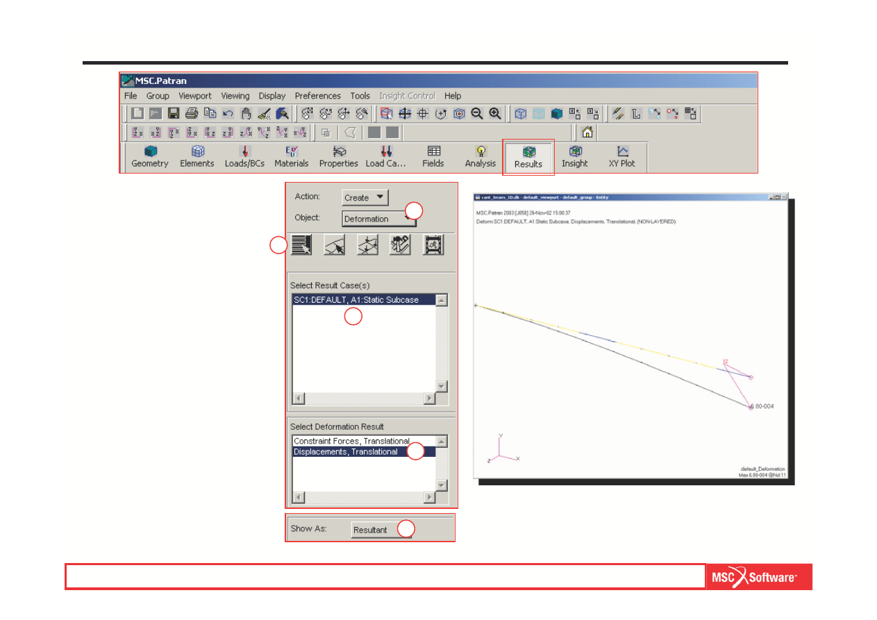
Step 14. View Results
a.
Results: Create /
Deformation.
b.
Select Results icon.
c.
Select A
1:Static Subcase
under Select Result Cases.
d.
Select Displacements,
Translational under Select
Deformation Result.
e.
Show As: Resultant.
f.
Apply.
a
b
c
d
e
MES w modelowaniu układów mechatronicznych lab. 1,2 (based on MSC tutorial WS13
WS13-23
PAT301, Workshop 13, December 2005
Copyright 2005 MSC.Software Corporation
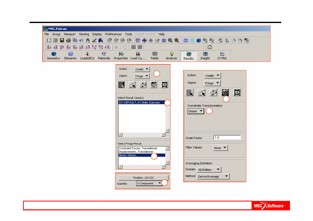
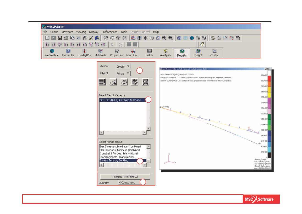
Step 14. View Results (Cont.)
a.
Results: Create / Fringe.
b.
Select A1:Static Subcase
under Select Result Cases.
c.
Select S
tress Tensor under
Select Fringe Result.
d.
Quantity: X Component.
e.
Select P
lot Options button.
f.
Coordinate Transformation:
Global.
g.
Apply.
a
b
c
d
e
f
MES w modelowaniu układów mechatronicznych lab. 1,2 (based on MSC tutorial WS13
WS13-24
PAT301, Workshop 13, December 2005
Copyright 2005 MSC.Software Corporation
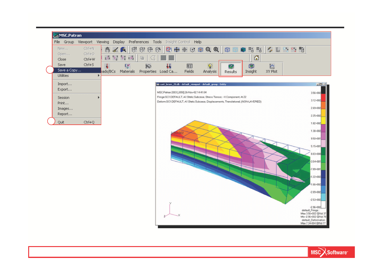
Step 15. Stress Results and Save a Copy of the Database
Display X component of stress fringe
plot. Save a copy of this database for
use later for a transient simulation.
a.
File / Save a Copy as...
b.
File name:
cant_beam_transient.db.
c.
Save.
d.
File / Quit.
a
d
MES w modelowaniu układów mechatronicznych lab. 1,2 (based on MSC tutorial WS13

WS13-25
PAT301, Workshop 13, December 2005
Copyright 2005 MSC.Software Corporation
Step 16. Create a New Database for 1D Element Model
Create a new database for 1D
element model.
a.
File / New.
b.
Enter cant_beam_1D as the
file name.
c.
Click O
K.
d.
Choose Default Tolerance.
e.
Select MSC.Nastran as the
Analysis Code.
f.
Select Structural as the
Analysis Type.
g.
Click O
K.
a
b
e
f
d
c
g
MES w modelowaniu układów mechatronicznych lab. 1,2 (based on MSC tutorial WS13
WS13-26
PAT301, Workshop 13, December 2005
Copyright 2005 MSC.Software Corporation
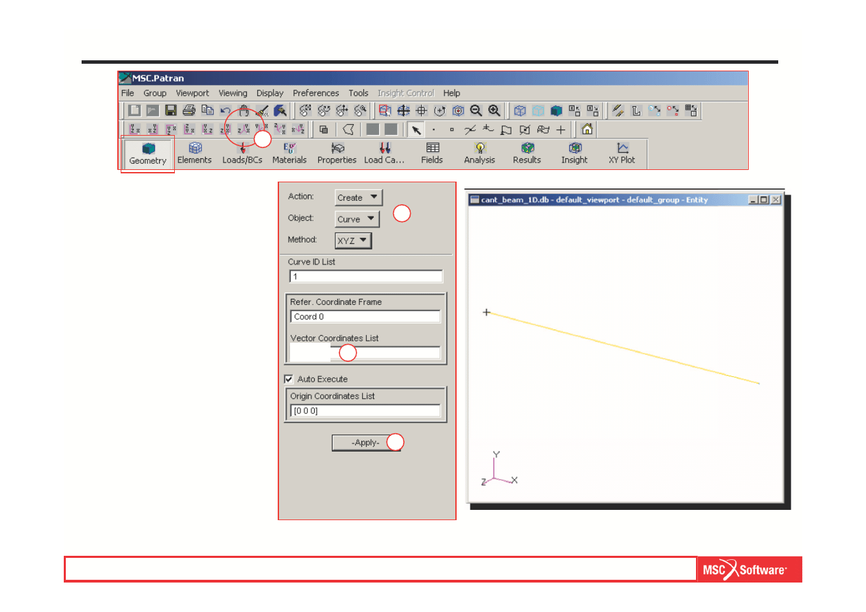
Step 17. Create Curve Geometry
a.
Geometry: Create / Curve /
XYZ.
b.
Select on Vector
Coordinates List and enter
< 50 0 0 >.
c.
Apply.
d.
Change view to I
so 1 View.
a
b
c
d
MES w modelowaniu układów mechatronicznych lab. 1,2 (based on MSC tutorial WS13
< 50 0 0 >
WS13-27
PAT301, Workshop 13, December 2005
Copyright 2005 MSC.Software Corporation
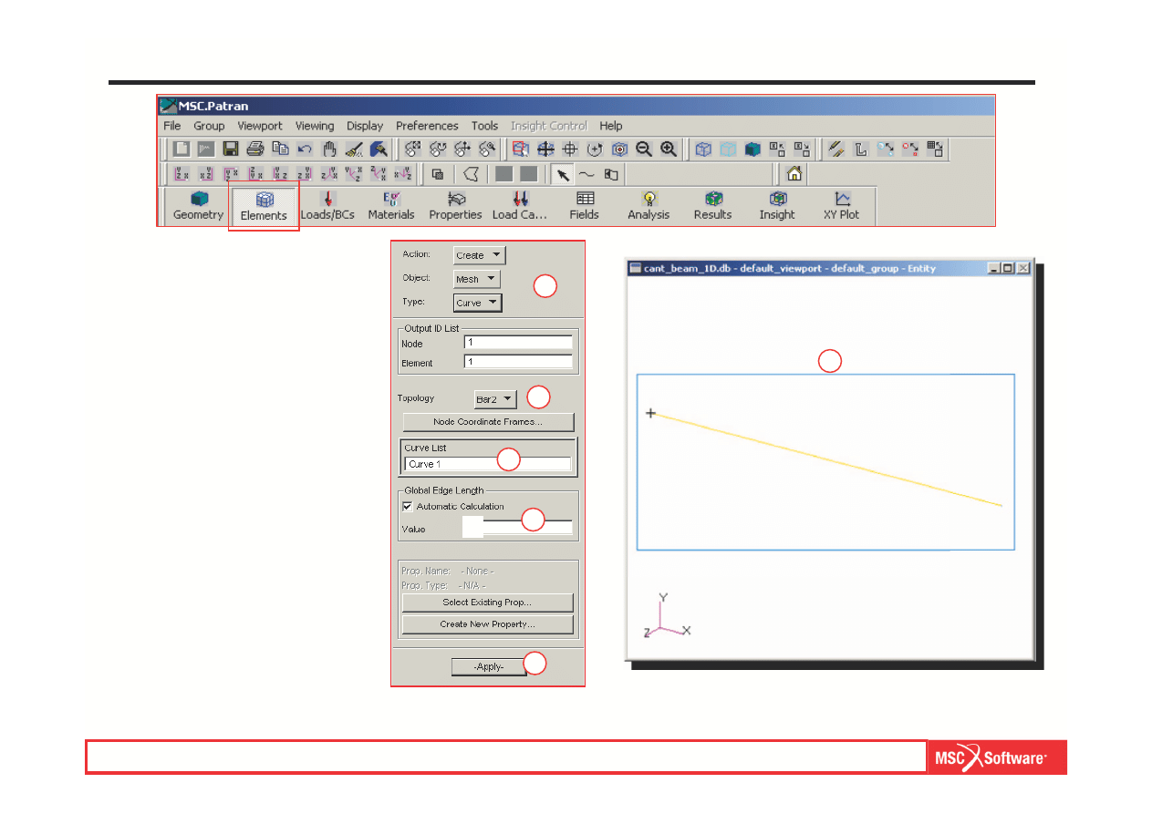
Step 18. Create 1D Element Mesh
a.
Elements: Create / Mesh /
Curve.
b.
Topology: Bar2.
c.
Click on Curve List and select
the curve.
d.
Enter 5 for Global Edge
Length.
e.
Apply.
a
b
c
d
e
c
MES w modelowaniu układów mechatronicznych lab. 1,2 (based on MSC tutorial WS13
5
WS13-28
PAT301, Workshop 13, December 2005
Copyright 2005 MSC.Software Corporation
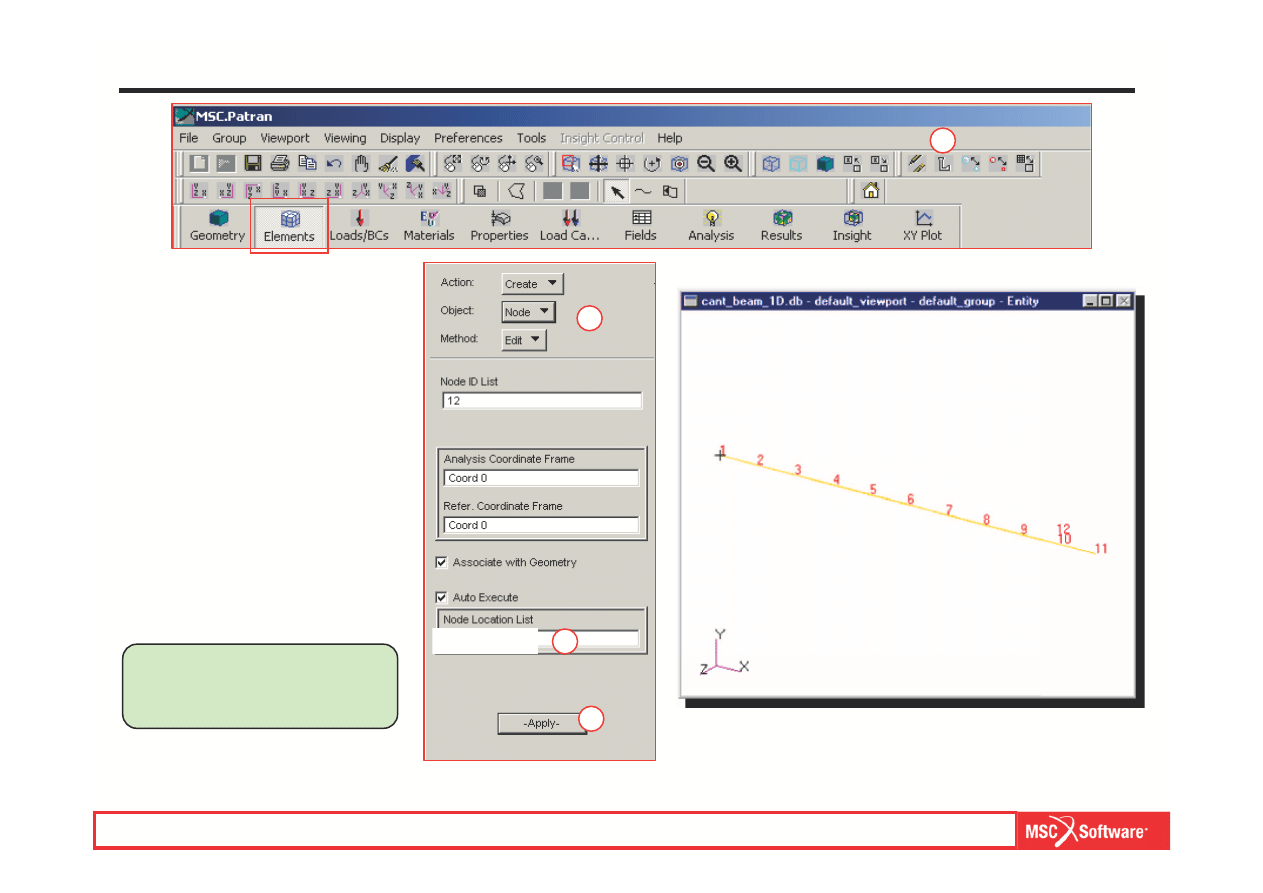
Step 19. Create a Rigid Link at Force End
Create a rigid link at the end of the
beam where the load will be
applied. That will offset the load so
it will be applied equivalent to that
for the prior 2D model.
a.
Turn on the node labels.
b.
Elements: Create / Node /
Edit.
c.
Select on Node Location List
and enter [50, 5, 7.5].
d.
Apply.
This will give Node 12,
where the load will be
applied.
b
d
a
c
MES w modelowaniu układów mechatronicznych lab. 1,2 (based on MSC tutorial WS13
[50, 5, 7.5]
WS13-29
PAT301, Workshop 13, December 2005
Copyright 2005 MSC.Software Corporation
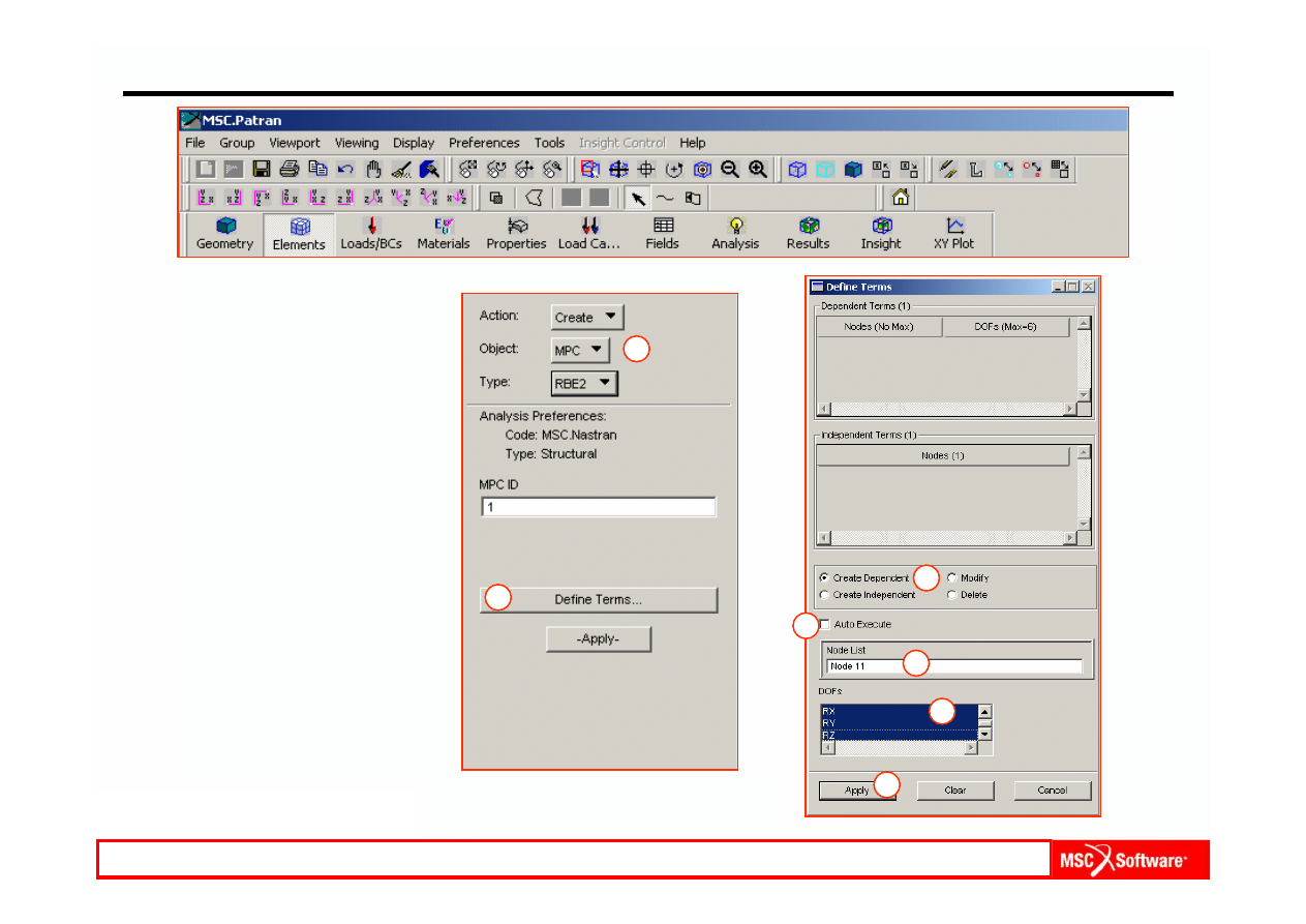
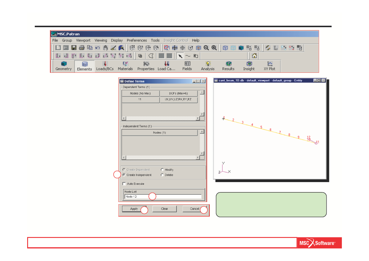
Step 19. Create a Rigid Link (Cont.)
a.
Elements: Create / MPC /
RBE2.
b.
Select Define Terms.
c.
Select C
reate Dependent.
d.
Turn off Auto Execute.
e.
Click on Node List and
select Node 11 from the
figure.
f.
DOFs: specify UX, UY, UZ,
RX, RY, RZ.
g.
Apply.
a
b
c
d
e
f
g
MES w modelowaniu układów mechatronicznych lab. 1,2 (based on MSC tutorial WS13
WS13-30
PAT301, Workshop 13, December 2005
Copyright 2005 MSC.Software Corporation
Step 19. Create a Rigid Link (Cont.)
a.
Notice that Create
Independent is active now.
b.
Click on Node List and
select Node 12 from the
figure.
c.
Apply.
d.
Cancel.
e.
Apply.
Notice that a magenta colored line was
drawn from Node 11 to Node 12. This
represents the rigid RBE2 MPC.
a
b
c
d
MES w modelowaniu układów mechatronicznych lab. 1,2 (based on MSC tutorial WS13
WS13-31
PAT301, Workshop 13, December 2005
Copyright 2005 MSC.Software Corporation
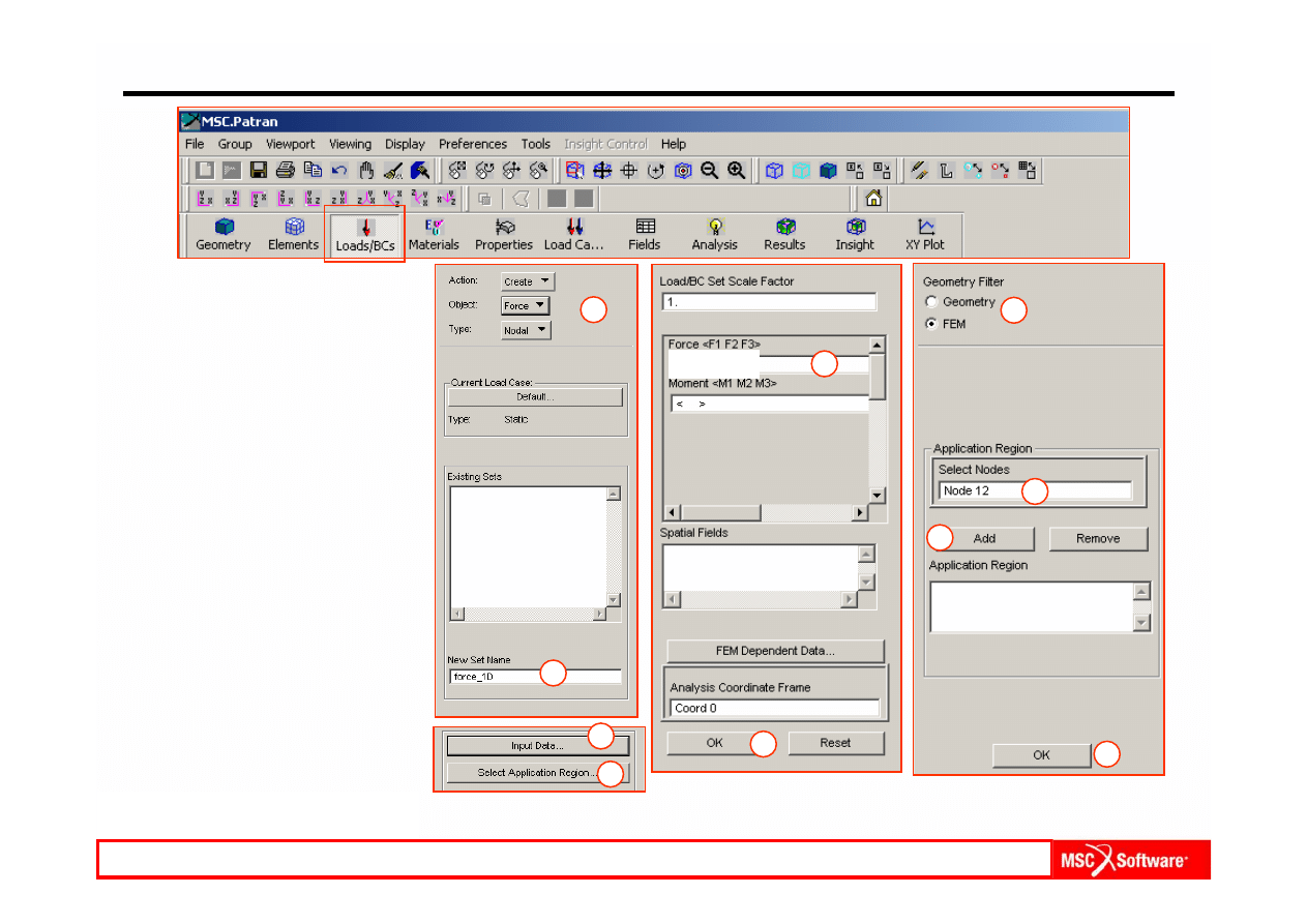
Step 20. Create a Concentrated Force
Apply a force at the free end of the
MPC.
a.
Loads / BCs: Create / Force
/ Nodal.
b.
Select on New Set Name
and enter force-1D.
c.
Input Data.
d.
Enter <
0 -150 0> for Force
<F1 F2 F3 >.
e.
OK.
f.
Select Application Region.
g.
Geometry Filter: FEM.
h.
Click on Select Nodes and
select Node 12.
i.
Add.
j.
OK.
k.
Apply.
a
b
c
d
e
f
g
h
i
j
MES w modelowaniu układów mechatronicznych lab. 1,2 (based on MSC tutorial WS13
<0 -150 0>
WS13-32
PAT301, Workshop 13, December 2005
Copyright 2005 MSC.Software Corporation
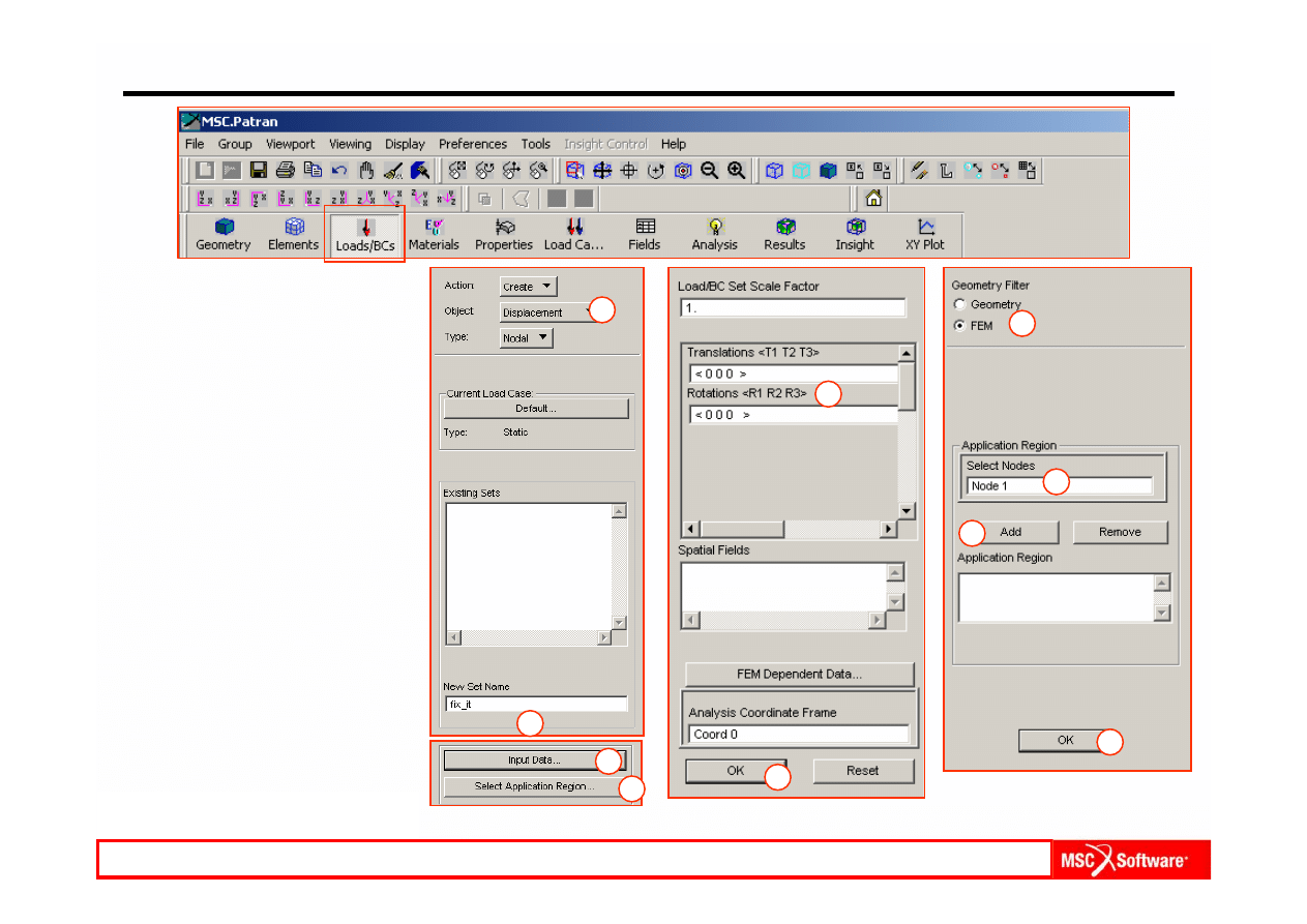
Step 21. Apply Constraints at Other End
a.
Loads / BCs: Create /
Displacements / Nodal.
b.
Select on New Set Name:
and enter fix_it.
c.
Select Input Data.
d.
Enter <
0 0 0> for
Translations <T1 T2 T3 >
and Rotations <R1 R2 R3>.
e.
OK.
f.
Click on Select Application
Region.
g.
Select FEM for Geometry
Filter.
h.
Click on Select Nodes and
select Node 1.
i.
Add.
j.
OK.
k.
Apply
a
b
c
d
e
f
g
h
i
j
MES w modelowaniu układów mechatronicznych lab. 1,2 (based on MSC tutorial WS13
WS13-33
PAT301, Workshop 13, December 2005
Copyright 2005 MSC.Software Corporation
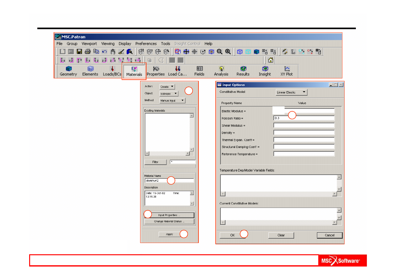
Step 22. Create Material Properties
a.
Materials: Create / Isotropic /
Manual Input.
b.
Select on Material Name
and enter aluminum2.
c.
Select Input Properties.
d.
Enter:
Elastic Modulus: 2e
5.
Poisson Ratio: 0.3.
e.
OK.
f.
Apply.
a
b
c
d
e
f
MES w modelowaniu układów mechatronicznych lab. 1,2 (based on MSC tutorial WS13
2e5
WS13-34
PAT301, Workshop 13, December 2005
Copyright 2005 MSC.Software Corporation
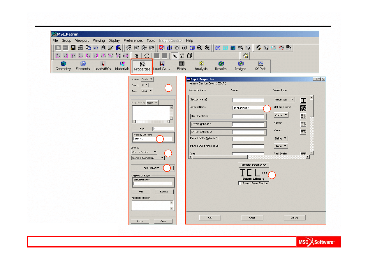
Step 23. Create Element Properties for the 1D Beam Topology
a.
Properties: Create / 1D /
Beam.
b.
Option(s): General Section /
Standard Formulation.
c.
Select Property Set Name and
enter alum_1D.
d.
Select Input Properties.
e.
From the Material Property
Sets, select aluminum2 for
Material Name.
f.
Select Create Sections Beam
Library.
a
b
c
d
e
f
MES w modelowaniu układów mechatronicznych lab. 1,2 (based on MSC tutorial WS13
WS13-35
PAT301, Workshop 13, December 2005
Copyright 2005 MSC.Software Corporation
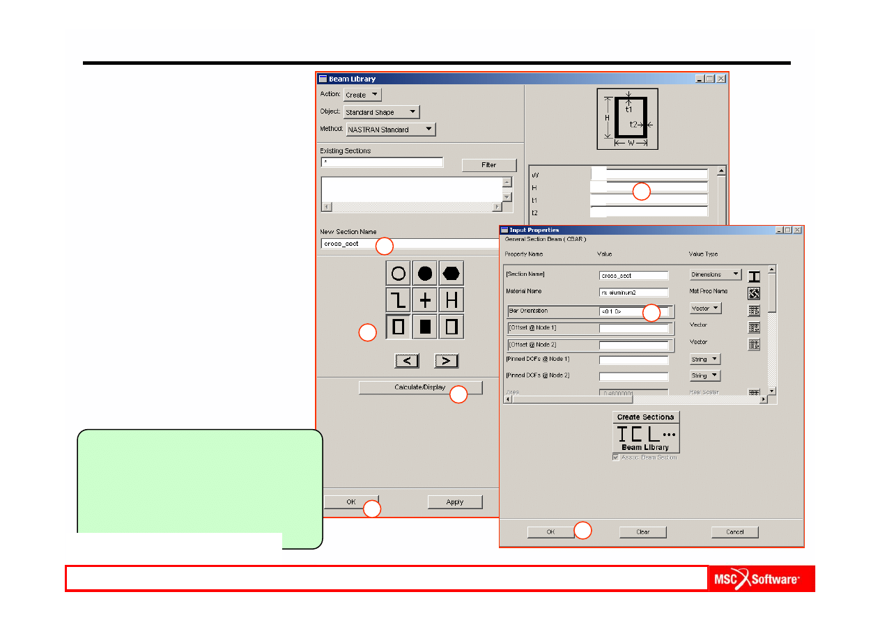
Step 23. Create Element Properties for the 1D Beam Topology (Cont.)
a.
In New Section Name:
cross_sect.
b.
Select the rectangular cross-
section button and enter:
W = 15, H = 10, t1 =1,
t2 =1.
c.
Calculate / Display.
d.
OK.
e.
Enter < 0 1 0 > in Bar
Orientation.
f.
OK.
g.
Click on Select Members and
select Curve 1.
h.
Add.
i.
Click A
pply.
j.
Display the cross-section to
scale under Display /
Load/BC /Elem. Props…
using Beam Display / 3D:
FullSpan + Offsets.
k.
Click Apply.
a
b
c
Notice that the name “cross_sect” now
appears in the Input Properties form
under Section Name. Area, Inertia
and Torsional Constant have values.
The values are ghosted out so that to
change them it is necessary to use the
Create Section button.
d
e
f
b
MES w modelowaniu układów mechatronicznych lab. 1,2 (based on MSC tutorial WS13
15
10
1
1
WS13-36
PAT301, Workshop 13, December 2005
Copyright 2005 MSC.Software Corporation
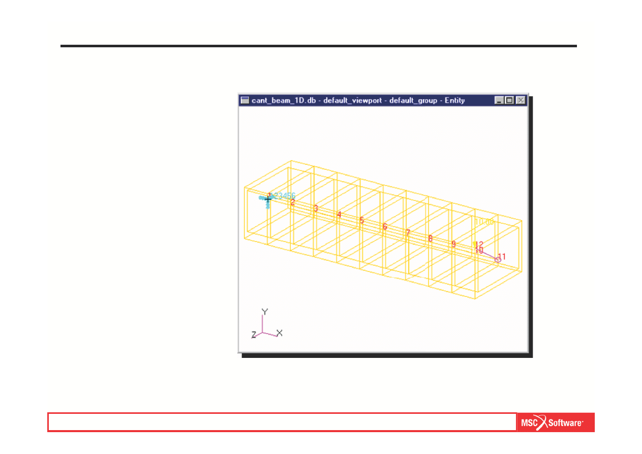
a.
This is the entire 1D model.
A representation of the
cross-section is shown,
even though the geometry is
only 1D.
Step 23. Create Element Properties for the 1D Beam Topology (Cont.)
MES w modelowaniu układów mechatronicznych lab. 1,2 (based on MSC tutorial WS13
WS13-37
PAT301, Workshop 13, December 2005
Copyright 2005 MSC.Software Corporation
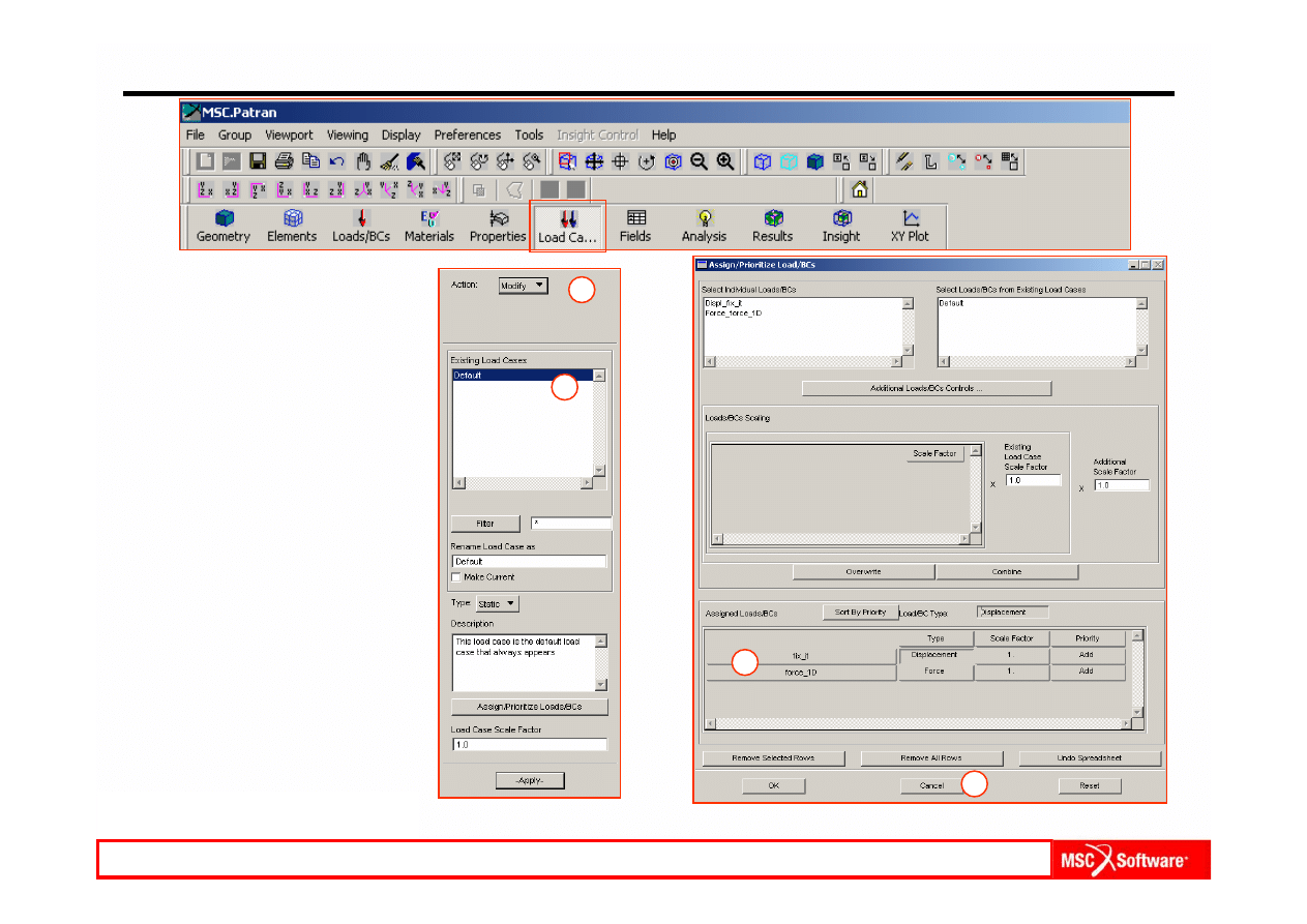
Step 24. Check Assignment of Loads and BC’s to Load Case
a.
Load Cases: Modify.
b.
Select Default in Select
Load Case to Modify.
c.
Check that all Loads and
BC’s are selected.
d.
Cancel.
a
b
c
d
MES w modelowaniu układów mechatronicznych lab. 1,2 (based on MSC tutorial WS13
WS13-38
PAT301, Workshop 13, December 2005
Copyright 2005 MSC.Software Corporation
Step 25. Run Analysis for 1D Beam
a.
Analysis: Analyze / Entire
Model / Full Run.
b.
Select Solution Type.
c.
Choose LINEAR STATIC for
Solution Type.
d.
OK.
e.
Apply.
b
c
d
a
MES w modelowaniu układów mechatronicznych lab. 1,2 (based on MSC tutorial WS13
WS13-39
PAT301, Workshop 13, December 2005
Copyright 2005 MSC.Software Corporation
Step 26. Read Results Under Analysis
Attach the .xdb file to read the
results.
a.
Analysis: Access Results /
Attach XDB / Result Entities.
b.
Click on Select Result File.
c.
Select and attach the
cant_beam_1D.xdb.
d.
OK.
e.
Apply.
c
d
a
b
e
MES w modelowaniu układów mechatronicznych lab. 1,2 (based on MSC tutorial WS13
WS13-40
PAT301, Workshop 13, December 2005
Copyright 2005 MSC.Software Corporation
Step 27. View Results
Create a Deformation plot .
a.
Results: Create /
Deformation.
b.
Select Results icon.
c.
Select A
1:Static Subcase
under Select Result Cases.
d.
Select Displacements,
Translational under Select
Deformation Result.
e.
Show As: Resultant.
f.
Apply.
a
b
c
d
e
MES w modelowaniu układów mechatronicznych lab. 1,2 (based on MSC tutorial WS13
WS13-41
PAT301, Workshop 13, December 2005
Copyright 2005 MSC.Software Corporation
Step 27. View Results (Cont.)
a.
Results: Create / Fringe.
b.
Select A1:Static Subcase
under Select Result Case(s).
c.
Select S
tress Tensor,
Bending under Select
Fringe Result.
d.
Quantity: X Component.
e.
Apply.
a
b
c
d
MES w modelowaniu układów mechatronicznych lab. 1,2 (based on MSC tutorial WS13
WS13-42
PAT301, Workshop 13, December 2005
Copyright 2005 MSC.Software Corporation
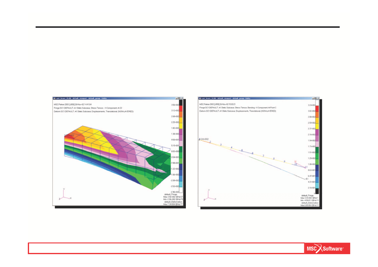
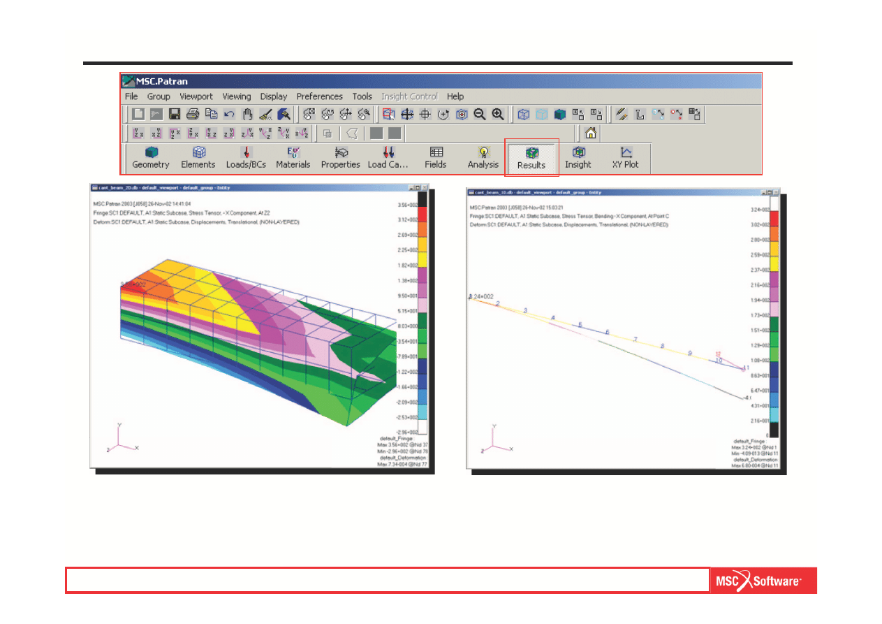
a.
Compare Results.
b.
This ends this exercise.
Step 28. Compare 2D and 1D Model Results
MES w modelowaniu układów mechatronicznych lab. 1,2 (based on MSC tutorial WS13
Wyszukiwarka
Podobne podstrony:
I9M1S1 Nawrot Gudanowicz lab2
IWP JP2 Lab2 Struktury
Lab2 OZE id 259328 Nieznany
MES 02
mes rama
lrm sprawozdanie kck lab2
LAB 4 Lab2 WprowadzenieMATLAB 2 Nieznany
MES, Polibuda MBM PWR 2012-2016, Sem. V, MES, koło
lab2(v2), Semestr III, Technologie wytwarzania
termo lab2 szczotka
Sprawozdanie MES
Grudziński Krawiec lab2# 10 2012
sprawko mes cw5 4 04 2014r
Badanie wyplywu cieczy ze zbior sprawozdanie z lab2 id 631079 (2)
lab2 3 3
program lab2 1JP3
lab2 7 id 259265 Nieznany
więcej podobnych podstron