165
CHAPTER 10
RADIO WAVES
ELECTROMAGNETIC WAVE PROPAGATION
1000. Source Of Radio Waves
Consider electric current as a flow of electrons along a
conductor between points of differing potential. A direct cur-
rent flows continuously in the same direction. This would
occur if the polarity of the electromotive force causing the
electron flow were constant, such as is the case with a battery.
If, however, the current is induced by the relative motion be-
tween a conductor and a magnetic field, such as is the case in
a rotating machine called a generator, then the resulting cur-
rent changes direction in the conductor as the polarity of the
electromotive force changes with the rotation of the genera-
tor’s rotor. This is known as alternating current.
The energy of the current flowing through the conduc-
tor is either dissipated as heat (an energy loss proportional
to both the current flowing through the conductor and the
conductor’s resistance) or stored in an electromagnetic field
oriented symmetrically about the conductor. The orienta-
tion of this field is a function of the polarity of the source
producing the current. When the current is removed from
the wire, this electromagnetic field will, after a finite time,
collapse back into the wire.
What would occur should the polarity of the current
source supplying the wire be reversed at a rate which great-
ly exceeds the finite amount of time required for the
electromagnetic field to collapse back upon the wire? In the
case of rapid pole reversal, another magnetic field, propor-
tional in strength but exactly opposite in magnetic
orientation to the initial field, will be formed upon the wire.
The initial magnetic field, its current source gone, cannot
collapse back upon the wire because of the existence of this
second, oriented electromagnetic field. Instead, it “detach-
es” from the wire and propagates out into space. This is the
basic principle of a radio antenna, which transmits a wave
at a frequency proportional to the rate of pole reversal and
at a speed equal to the speed of light.
1001. Radio Wave Terminology
The magnetic field strength in the vicinity of a conduc-
tor is directly proportional to the magnitude of the current
flowing through the conductor. Recall the discussion of al-
ternating current above. A rotating generator produces
current in the form of a sine wave. That is, the magnitude of
the current varies as a function of the relative position of the
rotating conductor and the stationary magnetic field used to
induce the current. The current starts at zero, increases to a
maximum as the rotor completes one quarter of its revolu-
tion, and falls to zero when the rotor completes one half of
its revolution. The current then approaches a negative max-
imum; then it once again returns to zero. This cycle can be
represented by a sine function.
The relationship between the current and the magnetic
field strength induced in the conductor through which the
current is flowing is shown in Figure 1001. Recall from the
discussion above that this field strength is proportional to the
magnitude of the current; that is, if the current is represented
by a sine wave function, then so too will be the magnetic field
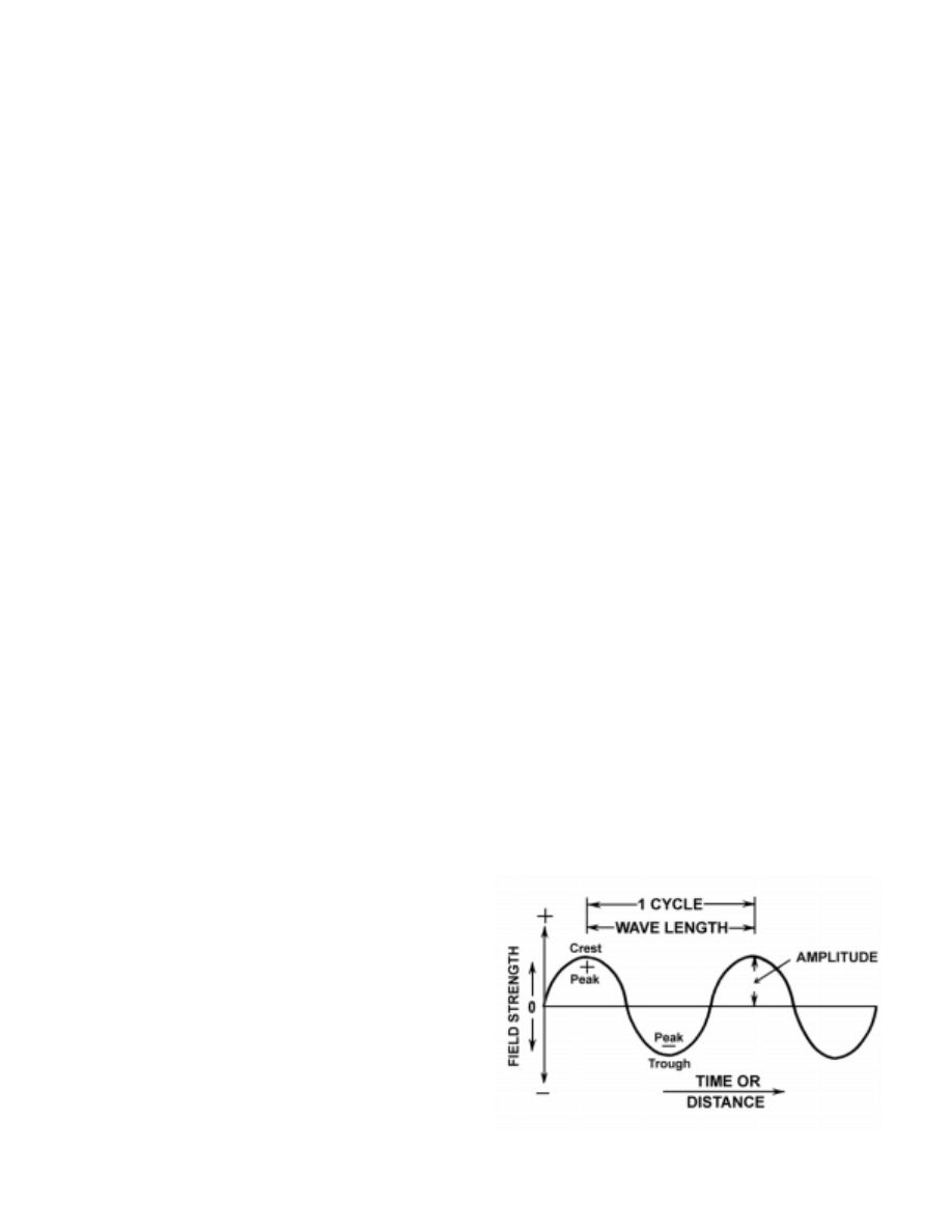
strength resulting from that current. This characteristic shape
of the field strength curve has led to the use of the term
“wave” when referring to electromagnetic propagation. The
maximum displacement of a peak from zero is called the am-
plitude. The forward side of any wave is called the wave
front. For a nondirectional antenna, each wave proceeds out-
ward as an expanding sphere (or hemisphere).
One cycle is a complete sequence of values, as from crest
to crest. The distance traveled by the energy during one cycle
is the wavelength, usually expressed in metric units (meters,
centimeters, etc.). The number of cycles repeated during unit
time (usually 1 second) is the frequency. This is given in hertz
(cycles per second). A kilohertz (kHz) is 1,000 cycles per sec-
ond. A megahertz (MHz) is 1,000,000 cycles per second.
Wavelength and frequency are inversely proportional.
The phase of a wave is the amount by which the cycle
has progressed from a specified origin. For most purposes it
Figure 1001. Radio wave terminology.

166
RADIO WAVES
is stated in circular measure, a complete cycle being consid-
ered 360
°
. Generally, the origin is not important, principal
interest being the phase relative to that of some other wave.
Thus, two waves having crests 1/4 cycle apart are said to be
90
°
“out of phase.” If the crest of one wave occurs at the
trough of another, the two are 180
°
out of phase.
1002. Electromagnetic Spectrum
The entire range of electromagnetic radiation frequen-
cies is called the electromagnetic spectrum. The
frequency range suitable for radio transmission, the radio
spectrum, extends from 10 kilohertz to 300,000 mega-
hertz. It is divided into a number of bands, as shown in
Table 1002. Below the radio spectrum, but overlapping it,
is the audio frequency band, extending from 20 to 20,000
hertz. Above the radio spectrum are heat and infrared, the
visible spectrum (light in its various colors), ultraviolet, X-
rays, gamma rays, and cosmic rays. These are included in
Table 1002. Waves shorter than 30 centimeters are usually
called microwaves.
1003. Polarization
Radio waves produce both electric and magnetic fields.
The direction of the electric component of the field is called
the polarization of the electromagnetic field. Thus, if the
electric component is vertical, the wave is said to be “verti-
cally polarized,” and if horizontal, “horizontally polarized.”
A wave traveling through space may be polarized in any di-
rection. One traveling along the surface of the earth is
always vertically polarized because the earth, a conductor,
short-circuits any horizontal component. The magnetic field
and the electric field are always mutually perpendicular.
1004. Reflection
When radio waves strike a surface, the surface reflects
them in the same manner as light waves. Radio waves of all
frequencies are reflected by the surface of the earth. The
strength of the reflected wave depends upon grazing angle
(the angle between the incident ray and the horizontal), type
of polarization, frequency, reflecting properties of the sur-
face, and divergence of the reflected ray. Lower frequency
results in greater penetration. At very low frequencies, us-
able radio signals can be received some distance below the
surface of the sea.
A phase change occurs when a wave is reflected from
the surface of the earth. The amount of the change varies with
the conductivity of the earth and the polarization of the wave,
reaching a maximum of 180
°
for a horizontally polarized
wave reflected from sea water (considered to have infinite
conductivity). When direct waves (those traveling from
transmitter to receiver in a relatively straight line, without re-
flection) and reflected waves arrive at a receiver, the total
signal is the vector sum of the two. If the signals are in phase,
they reinforce each other, producing a stronger signal. If
there is a phase difference, the signals tend to cancel each
other, the cancellation being complete if the phase difference
is 180
°
and the two signals have the same amplitude. This in-
teraction of waves is called wave interference. A phase
difference may occur because of the change of phase of a re-
flected wave, or because of the longer path followed by it.
The second effect decreases with greater distance between
transmitter and receiver, for under these conditions the dif-
ference in path lengths is smaller. At lower frequencies there
is no practical solution to interference caused in this way. For
VHF and higher frequencies, the condition can be improved
Band
Abbreviation
Range of frequency
Range of wavelength
Audio frequency
AF
20 to 20,000 Hz
15,000,000 to 15,000 m
Radio frequency
RF
10 kHz to 300,000 MHz
30,000 m to 0.1 cm
Very low frequency
VLF
10 to 30 kHz
30,000 to 10,000 m
Low frequency
LF
30 to 300 kHz
10,000 to 1,000 m
Medium frequency
MF
300 to 3,000 kHz
1,000 to 100 m
High frequency
HF
3 to 30 MHz
100 to 10 m
Very high frequency
VHF
30 to 300 MHz
10 to 1 m
Ultra high frequency
UHF
300 to 3,000 MHz
100 to 10 cm
Super high frequency
SHF
3,000 to 30,000 MHz
10 to 1 cm
Extremely high
frequency
EHF
30,000 to 300,000 MHz
1 to 0.1 cm
Heat and infrared*
10
6
to 3.9
×
10
8
MHz
0.03 to 7.6
×
10
-5
cm
Visible spectrum*
3.9
×
10
8
to 7.9
×
10
8
MHz
7.6
×
10
-5
to 3.8
×
10
-5
cm
Ultraviolet*
7.9
×
10
8
to 2.3
×
10
10
MHz
3.8
×
10
-5
to 1.3
×
10
-6
cm
X-rays*
2..0
×
10
9
to 3.0
×
10
13
MHz
1.5
×
10
-5
to 1.0
×
10
-9
cm
Gamma rays*
2.3
×
10
12
to 3.0
×
10
14
MHz
1.3
×
10
-8
to 1.0
×
10
-10
cm
Cosmic rays*
>4.8
×
10
15
MHz
<6.2
×
10
-12
cm
* Values approximate.
Table 1002. Electromagnetic spectrum.

RADIO WAVES
167
by elevating the antenna, if the wave is vertically polarized.
Additionally, interference at higher frequencies can be more
nearly eliminated because of the greater ease of beaming the
signal to avoid reflection.
Reflections may also occur from mountains, trees, and
other obstacles. Such reflection is negligible for lower fre-
quencies, but becomes more prevalent as frequency
increases. In radio communication, it can be reduced by us-
ing directional antennas, but this solution is not always
available for navigational systems.
Various reflecting surfaces occur in the atmosphere. At
high frequencies, reflections take place from rain. At still
higher frequencies, reflections are possible from clouds, par-
ticularly rain clouds. Reflections may even occur at a sharply
defined boundary surface between air masses, as when
warm, moist air flows over cold, dry air. When such a surface
is roughly parallel to the surface of the earth, radio waves
may travel for greater distances than normal The principal
source of reflection in the atmosphere is the ionosphere.
1005. Refraction
Refraction of radio waves is similar to that of light
waves. Thus, as a signal passes from air of one density to
that of a different density, the direction of travel is altered.
The principal cause of refraction in the atmosphere is the
difference in temperature and pressure occurring at various
heights and in different air masses.
Refraction occurs at all frequencies, but below 30 MHz
the effect is small as compared with ionospheric effects,
diffraction, and absorption. At higher frequencies, refrac-
tion in the lower layer of the atmosphere extends the radio
horizon to a distance about 15 percent greater than the vis-
ible horizon. The effect is the same as if the radius of the
earth were about one-third greater than it is and there were
no refraction.
Sometimes the lower portion of the atmosphere be-
comes stratified. This stratification results in nonstandard
temperature and moisture changes with height. If there is a
marked temperature inversion or a sharp decrease in water
vapor content with increased height, a horizontal radio duct
may be formed. High frequency radio waves traveling hor-
izontally within the duct are refracted to such an extent that
they remain within the duct, following the curvature of the
earth for phenomenal distances. This is called super-re-
fraction. Maximum results are obtained when both
transmitting and receiving antennas are within the duct.
There is a lower limit to the frequency affected by ducts. It
varies from about 200 MHz to more than 1,000 MHz.
At night, surface ducts may occur over land due to
cooling of the surface. At sea, surface ducts about 50 feet
thick may occur at any time in the trade wind belt. Surface
ducts 100 feet or more in thickness may extend from land
out to sea when warm air from the land flows over the cool-
er ocean surface. Elevated ducts from a few feet to more
than 1,000 feet in thickness may occur at elevations of
1,000 to 5,000 feet, due to the settling of a large air mass.
This is a frequent occurrence in Southern California and
certain areas of the Pacific Ocean.
A bending in the horizontal plane occurs when a
groundwave crosses a coast at an oblique angle. This is due
to a marked difference in the conducting and reflecting prop-
erties of the land and water over which the wave travels. The
effect is known as coastal refraction or land effect.
1006. The Ionosphere
Since an atom normally has an equal number of nega-
tively charged electrons and positively charged protons, it
is electrically neutral. An ion is an atom or group of atoms
which has become electrically charged, either positively or
negatively, by the loss or gain of one or more electrons.
Loss of electrons may occur in a variety of ways. In the
atmosphere, ions are usually formed by collision of atoms
with rapidly moving particles, or by the action of cosmic
rays or ultraviolet light. In the lower portion of the atmo-
sphere, recombination soon occurs, leaving a small
percentage of ions. In thin atmosphere far above the surface
of the earth, however, atoms are widely separated and a
large number of ions may be present. The region of numer-
ous positive and negative ions and unattached electrons is
called the ionosphere. The extent of ionization depend-
supon the kinds of atoms present in the atmosphere, the
density of the atmosphere, and the position relative to the
sun (time of day and season). After sunset, ions and elec-
tronsrecombine faster than they are separated, decreasing
the ionization of the atmosphere.
An electron can be separated from its atom only by the
application of greater energy than that holding the electron.
Since the energy of the electron depends primarily upon the
kind of an atom of which it is a part, and its position relative
to the nucleus of that atom, different kinds of radiation may
cause ionization of different substances.
In the outermost regions of the atmosphere, the density
is so low that oxygen exists largely as separate atoms, rather
than combining as molecules as it does nearer the surface of
the earth. At great heights the energy level is low and ion-
ization from solar radiation is intense. This is known as the
F layer. Above this level the ionization decreases because
of the lack of atoms to be ionized. Below this level it de-
creases because the ionizing agent of appropriate energy
has already been absorbed. During daylight, two levels of
maximum F ionization can be detected, the F
2
layer at about
125 statute miles above the surface of the earth, and the F
1
layer at about 90 statute miles. At night, these combine to
form a single F layer.
At a height of about 60 statute miles, the solar radiation
not absorbed by the F layer encounters, for the first time, large
numbers of oxygen molecules. A new maximum ionization
occurs, known as the E layer. The height of this layer is quite
constant, in contrast with the fluctuating F layer. At night the
E layer becomes weaker by two orders of magnitude.
168
RADIO WAVES
Below the E layer, a weak D layer forms at a height of
about 45 statute miles, where the incoming radiation en-
counters ozone for the first time. The D layer is the
principal source of absorption of HF waves, and of reflec-
tion of LF and VLF waves during daylight.
1007. The Ionosphere And Radio Waves
When a radio wave encounters a particle having an
electric charge, it causes that particle to vibrate. The vibrat-
ing particle absorbs electromagnetic energy from the radio
wave and radiates it. The net effect is a change of polariza-
tion and an alteration of the path of the wave. That portion
of the wave in a more highly ionized region travels faster,
causing the wave front to tilt and the wave to be directed to-
ward a region of less intense ionization.
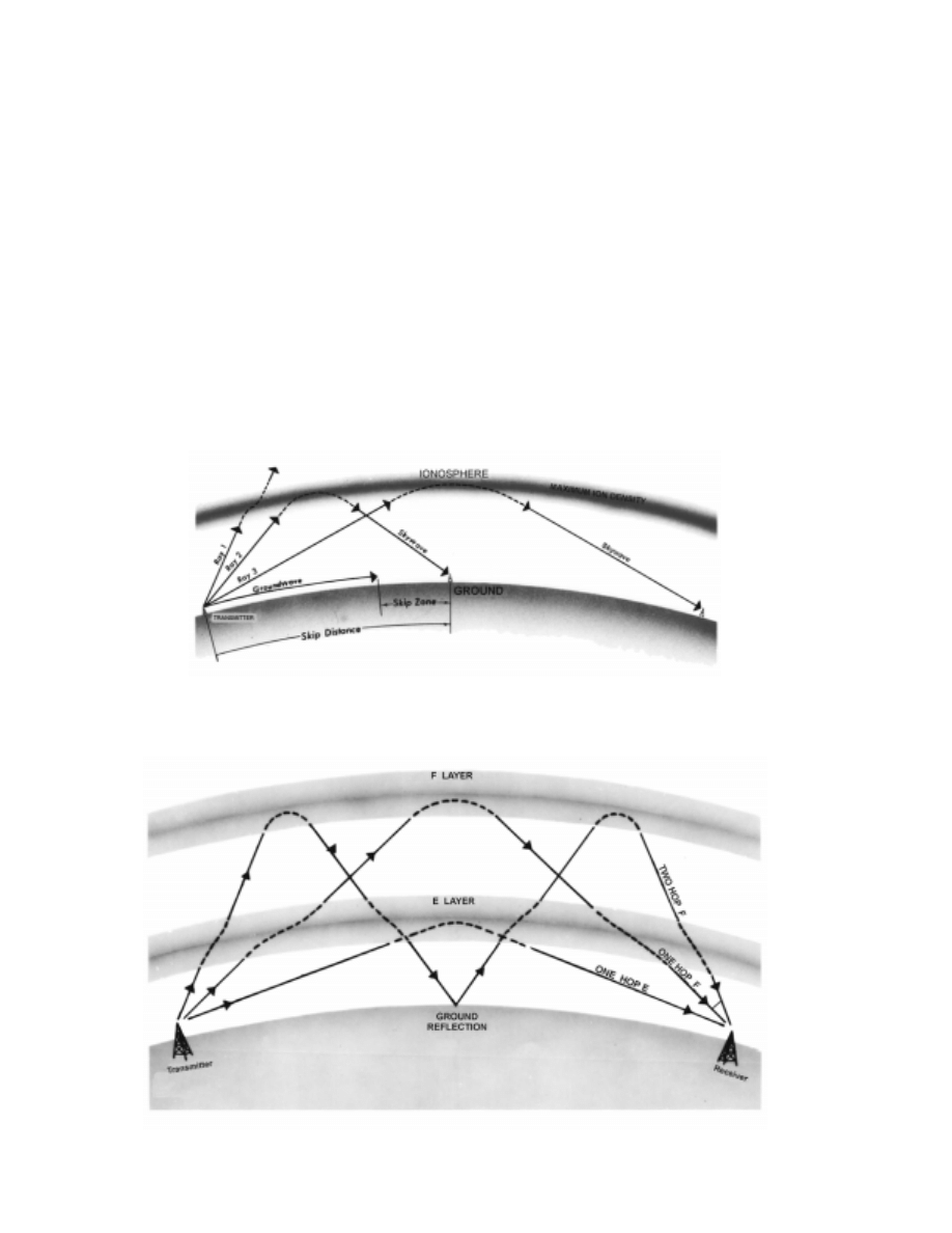
Refer to Figure 1007a, in which a single layer of the
ionosphere is considered. Ray 1 enters the ionosphere at
such an angle that its path is altered, but it passes through
and proceeds outward into space. As the angle with the hor-
izontal decreases, a critical value is reached where ray 2 is
bent or reflected back toward the earth. As the angle is still
further decreased, such as at 3, the return to earth occurs at
a greater distance from the transmitter.
A wave reaching a receiver by way of the ionosphere
is called a skywave. This expression is also appropriately
applied to a wave reflected from an air mass boundary. In
common usage, however, it is generally associated with the
ionosphere. The wave which travels along the surface of the
earth is called a groundwave. At angles greater than the
critical angle, no skywave signal is received. Therefore,
there is a minimum distance from the transmitter at which
Figure 1007a. The effect of the ionosphere on radio waves.
Figure 1007b. Various paths by which a skywave signal might be received.

RADIO WAVES
169
skywaves can be received. This is called the skip distance,
shown in Figure 1007a. If the groundwave extends out for
less distance than the skip distance, a skip zone occurs, in
which no signal is received.
The critical radiation angle depends upon the intensity
of ionization, and the frequency of the radio wave. As the fre-
quency increases, the angle becomes smaller. At frequencies
greater than about 30 MHz virtually all of the energy pene-
trates through or is absorbed by the ionosphere. Therefore, at
any given receiver there is a maximum usable frequency if
skywaves are to be utilized. The strongest signals are re-
ceived at or slightly below this frequency. There is also a
lower practical frequency beyond which signals are too weak
to be of value. Within this band the optimum frequency can
be selected to give best results. It cannot be too near the max-
imum usable frequency because this frequency fluctuates
with changes of intensity within the ionosphere. During mag-
netic storms the ionosphere density decreases. The maximum
usable frequency decreases, and the lower usable frequency
increases. The band of usable frequencies is thus narrowed.
Under extreme conditions it may be completely eliminated,
isolating the receiver and causing a radio blackout.
Skywave signals reaching a given receiver may arrive
by any of several paths, as shown in Figure 1007b. A signal
which undergoes a single reflection is called a “one-hop”
signal, one which undergoes two reflections with a ground
reflection between is called a “two-hop” signal, etc. A
“multihop” signal undergoes several reflections. The layer
at which the reflection occurs is usually indicated, also, as
“one-hop E,” “two-hop F,” etc.
Because of the different paths and phase changes oc-
curring at each reflection, the various signals arriving at a
receiver have different phase relationships. Since the densi-
ty of the ionosphere is continually fluctuating, the strength
and phase relationships of the various signals may undergo
an almost continuous change. Thus, the various signals may
reinforce each other at one moment and cancel each other
at the next, resulting in fluctuations of the strength of the to-
tal signal received. This is called fading. This phenomenon
may also be caused by interaction of components within a
single reflected wave, or changes in its strength due to
changes in the reflecting surface. Ionospheric changes are
associated with fluctuations in the radiation received from
the sun, since this is the principal cause of ionization. Sig-
nals from the F layer are particularly erratic because of the
rapidly fluctuating conditions within the layer itself.
The maximum distance at which a one-hop E signal can be
received is about 1,400 miles. At this distance the signal leaves
the transmitter in approximately a horizontal direction. A one-
hop F signal can be received out to about 2,500 miles. At low
frequencies groundwaves extend out for great distances.
A skywave may undergo a change of polarization during
reflection from the ionosphere, accompanied by an alteration
in the direction of travel of the wave. This is called polariza-
tion error. Near sunrise and sunset, when rapid changes are
occurring in the ionosphere, reception may become erratic and
polarization error a maximum. This is called night effect.
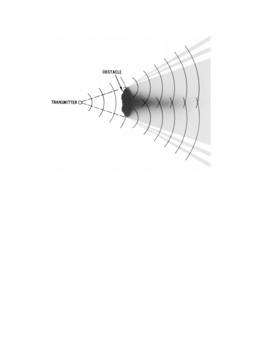
1008. Diffraction
When a radio wave encounters an obstacle, its energy is
reflected or absorbed, causing a shadow beyond the obsta-
cle. However, some energy does enter the shadow area
because of diffraction. This is explained by Huygens’ prin-
ciple, which states that every point on the surface of a wave
front is a source of radiation, transmitting energy in all direc-
tions ahead of the wave. No noticeable effect of this
principle is observed until the wave front encounters an ob-
stacle, which intercepts a portion of the wave. From the edge
of the obstacle, energy is radiated into the shadow area, and
also outside of the area. The latter interacts with energy from
other parts of the wave front, producing alternate bands in
which the secondary radiation reinforces or tends to cancel
the energy of the primary radiation. Thus, the practical effect
of an obstacle is a greatly reduced signal strength in the
shadow area, and a disturbed pattern for a short distance out-
side the shadow area. This is illustrated in Figure 1008.
The amount of diffraction is inversely proportional to
the frequency, being greatest at very low frequencies.
1009. Absorption And Scattering
The amplitude of a radio wave expanding outward
through space varies inversely with distance, weakening
with increased distance. The decrease of strength with dis-
tance is called attenuation. Under certain conditions the
attenuation is greater than in free space.
A wave traveling along the surface of the earth loses a
certain amount of energy to the earth. The wave is diffract-
ed downward and absorbed by the earth. As a result of this
absorption, the remainder of the wave front tilts downward,
resulting in further absorption by the earth. Attenuation is
greater over a surface which is a poor conductor. Relatively
little absorption occurs over sea water, which is an excellent
conductor at low frequencies, and low frequency ground-
waves travel great distances over water.
A skywave suffers an attenuation loss in its encounter
with the ionosphere. The amount depends upon the height
and composition of the ionosphere as well as the frequency
of the radio wave. Maximum ionospheric absorption occurs
at about 1,400 kHz.
In general, atmospheric absorption increases with fre-
quency. It is a problem only in the SHF and EHF frequency
range. At these frequencies, attenuation is further increased
by scattering due to reflection by oxygen, water vapor, wa-
ter droplets, and rain in the atmosphere.
1010. Noise
Unwanted signals in a receiver are called interference.
The intentional production of such interference to obstruct
communication is called jamming. Unintentional interfer-
170
RADIO WAVES
ence is called noise.
Noise may originate within the receiver. Hum is usual-
ly the result of induction from neighboring circuits carrying
alternating current. Irregular crackling or sizzling sounds
may be caused by poor contacts or faulty components with-
in the receiver. Stray currents in normal components causes
some noise. This source sets the ultimate limit of sensitivity
that can be achieved in a receiver. It is the same at any
frequency.
Noise originating outside the receiver may be either
man-made or natural. Man-made noises originate in electri-
cal appliances, motor and generator brushes, ignition
systems, and other sources of sparks which transmit electro-
magnetic signals that are picked up by the receiving antenna.
Natural noise is caused principally by discharge of stat-
ic electricity in the atmosphere. This is called atmospheric
noise, atmospherics, or static. An extreme example is a
thunderstorm. An exposed surface may acquire a consider-
able charge of static electricity. This may be caused by
friction of water or solid particles blown against or along
such a surface. It may also be caused by splitting of a water
droplet which strikes the surface, one part of the droplet re-
quiring a positive charge and the other a negative charge.
These charges may be transferred to the surface. The charge
tends to gather at points and ridges of the conducting sur-
face, and when it accumulates to a sufficient extent to
overcome the insulating properties of the atmosphere, it
discharges into the atmosphere. Under suitable conditions
this becomes visible and is known as St. Elmo’s fire, which
is sometimes seen at mastheads, the ends of yardarms, etc.
Atmospheric noise occurs to some extent at all fre-
quencies but decreases with higher frequencies. Above
about 30 MHz it is not generally a problem.
1011. Antenna Characteristics
Antenna design and orientation have a marked effect
upon radio wave propagation. For a single-wire antenna,
strongest signals are transmitted along the perpendicular to
the wire, and virtually no signal in the direction of the wire.
For a vertical antenna, the signal strength is the same in all
horizontal directions. Unless the polarization undergoes a
change during transit, the strongest signal received from a
vertical transmitting antenna occurs when the receiving an-
tenna is also vertical.
For lower frequencies the radiation of a radio signal
takes place by interaction between the antenna and the
ground. For a vertical antenna, efficiency increases with
greater length of the antenna. For a horizontal antenna, ef-
ficiency increases with greater distance between antenna
and ground. Near-maximum efficiency is attained when
this distance is one-half wavelength. This is the reason for
elevating low frequency antennas to great heights. Howev-
er, at the lowest frequencies, the required height becomes
Figure 1008. Diffraction.

RADIO WAVES
171
prohibitively great. At 10 kHz it would be about 8 nautical
miles for a half-wavelength antenna. Therefore, lower fre-
quency antennas are inherently inefficient. This is partly
offset by the greater range of a low frequency signal of the
same transmitted power as one of higher frequency.
At higher frequencies, the ground is not used, both con-
ducting portions being included in a dipole antenna. Not
only can such an antenna be made efficient, but it can al-
sobe made sharply directive, thus greatly increasing the
strength of the signal transmitted in a desired direction.
The power received is inversely proportional to the
square of the distance from the transmitter, assuming there
is no attenuation due to absorption or scattering.
1012. Range
The range at which a usable signal is received depends
upon the power transmitted, the sensitivity of the receiver,
frequency, route of travel, noise level, and perhaps other
factors. For the same transmitted power, both the ground-
wave and skywave ranges are greatest at the lowest
frequencies, but this is somewhat offset by the lesser effi-
ciency of antennas for these frequencies. At higher
frequencies, only direct waves are useful, and the effective
range is greatly reduced. Attenuation, skip distance, ground
reflection, wave interference, condition of the ionosphere,
atmospheric noise level, and antenna design all affect the
distance at which useful signals can be received.
1013. Radio Wave Propagation
Frequency is an important consideration in radio wave
propagation. The following summary indicates the principal ef-
fects associated with the various frequency bands, starting with
the lowest and progressing to the highest usable radio frequency.
Very Low Frequency (VLF, 10 to 30 kHz): The VLF
signals propagate between the bounds of the ionosphere and
the earth and are thus guided around the curvature of the
earth to great distances with low attenuation and excellent
stability. Diffraction is maximum. Because of the long
wavelength, large antennas are needed, and even these are
inefficient, permitting radiation of relatively small amounts
of power. Magnetic storms have little effect upon transmis-
sion because of the efficiency of the “earth-ionosphere
waveguide.” During such storms, VLF signals may consti-
tute the only source of radio communication over great
distances. However, interference from atmospheric noise
may be troublesome. Signals may be received from below
the surface of the sea.
Low Frequency (LF, 30 to 300 kHz): As frequency is in-
creased to the LF band and diffraction decreases, there is
greater attenuation with distance, and range for a given power
output falls off rapidly. However, this is partly offset by more
efficient transmitting antennas. LF signals are most stable
within groundwave distance of the transmitter. A wider band-
width permits pulsed signals at 100 kHz. This allows
separation of the stable groundwave pulse from the variable
skywave pulse up to 1,500 km, and up to 2,000 km for over-
water paths. The frequency for Loran C is in the LF band. This
band is also useful for radio direction finding and time
dissemination.
Medium Frequency (MF, 300 to 3,000 kHz): Ground-
waves provide dependable service, but the range for a given
power is reduced greatly. This range varies from about 400
miles at the lower portion of the band to about 15 miles at
the upper end for a transmitted signal of 1 kilowatt. These
values are influenced, however, by the power of the trans-
mitter, the directivity and efficiency of the antenna, and the
nature of the terrain over which signals travel. Elevating the
antenna to obtain direct waves may improve the transmis-
sion. At the lower frequencies of the band, skywaves are
available both day and night. As the frequency is increased,
ionospheric absorption increases to a maximum at about
1,400 kHz. At higher frequencies the absorption decreases,
permitting increased use of skywaves. Since the ionosphere
changes with the hour, season, and sunspot cycle, the reli-
ability of skywave signals is variable. By careful selection
of frequency, ranges of as much as 8,000 miles with 1 kilo-
watt of transmitted power are possible, using multihop
signals. However, the frequency selection is critical. If it is
too high, the signals penetrate the ionosphere and are lost in
space. If it is too low, signals are too weak. In general, sky-
wave reception is equally good by day or night, but lower
frequencies are needed at night. The standard broadcast
band for commercial stations (535 to 1,605 kHz) is in the
MF band.
High Frequency (HF, 3 to 30 MHz): As with higher me-
dium frequencies, the groundwave range of HF signals is
limited to a few miles, but the elevation of the antenna may in-
crease the direct-wave distance of transmission. Also, the
height of the antenna does have an important effect upon sky-
wave transmission because the antenna has an “image” within
the conducting earth. The distance between antenna and image
is related to the height of the antenna, and this distance is as
critical as the distance between elements of an antenna system.
Maximum usable frequencies fall generally within the HF
band. By day this may be 10 to 30 MHz, but during the night
it may drop to 8 to 10 MHz. The HF band is widely used for
ship-to-ship and ship-to-shore communication.
Very High Frequency (VHF, 30 to 300 MHz): Com-
munication is limited primarily to the direct wave, or the
direct wave plus a ground-reflected wave. Elevating the an-
tenna to increase the distance at which direct waves can be
used results in increased distance of reception, even though
some wave interference between direct and ground-reflect-
ed waves is present. Diffraction is much less than with
lower frequencies, but it is most evident when signals cross
sharp mountain peaks or ridges. Under suitable conditions,
reflections from the ionosphere are sufficiently strong to be
useful, but generally they are unavailable. There is relative-
ly little interference from atmospheric noise in this band.
Reasonably efficient directional antennas are possible with

172
RADIO WAVES
VHF. The VHF band is much used for communication.
Ultra High Frequency (UHF, 300 to 3,000 MHz):
Skywaves are not used in the UHF band because the iono-
sphere is not sufficiently dense to reflect the waves, which
pass through it into space. Groundwaves and ground-re-
flected waves are used, although there is some wave
interference. Diffraction is negligible, but the radio horizon
extends about 15 percent beyond the visible horizon, due
principally to refraction. Reception of UHF signals is virtu-
ally free from fading and interference by atmospheric noise.
Sharply directive antennas can be produced for transmis-
sion in this band, which is widely used for ship-to-ship and
ship-to-shore communication.
Super High Frequency (SHF, 3,000 to 30,000 MHz):
In the SHF band, also known as the microwave or as the
centimeter wave band, there are no skywaves, transmission
being entirely by direct and ground-reflected waves. Dif-
fraction and interference by atmospheric noise are virtually
nonexistent. Highly efficient, sharply directive antennas
can be produced. Thus, transmission in this band is similar
to that of UHF, but with the effects of shorter waves being
greater. Reflection by clouds, water droplets, dust particles,
etc., increases, causing greater scattering, increased wave
interference, and fading. The SHF band is used for marine
navigational radar.
Extremely High Frequency (EHF, 30,000 to 300,000
MHz): The effects of shorter waves are more pronounced in
the EHF band, transmission being free from wave interfer-
ence, diffraction, fading, and interference by atmospheric
noise. Only direct and ground-reflected waves are avail-
able. Scattering and absorption in the atmosphere are
pronounced and may produce an upper limit to the frequen-
cy useful in radio communication.
1014. Regulation Of Frequency Use
While the characteristics of various frequencies are im-
portant to the selection of the most suitable one for any
given purpose, these are not the only considerations. Con-
fusion and extensive interference would result if every
userhad complete freedom of selection. Some form of reg-
ulation is needed. The allocation of various frequency
bands to particular uses is a matter of international agree-
ment. Within the United States, the Federal
Communications Commission has responsibility for autho-
rizing use of particular frequencies. In some cases a given
frequency is allocated to several widely separated transmit-
ters, but only under conditions which minimize
interference, such as during daylight hours. Interference be-
tween stations is further reduced by the use of channels,
each of a narrow band of frequencies. Assigned frequencies
are separated by an arbitrary band of frequencies that are
not authorized for use. In the case of radio aids to naviga-
tion and ship communications bands of several channels are
allocated, permitting selection of band and channel by the
user.
1015. Types Of Radio Transmission
A series of waves transmitted at constant frequency and
amplitude is called a continuous wave (CW). This cannot be
heard except at the very lowest radio frequencies, when it
may produce, in a receiver, an audible hum of high pitch.
Although a continuous wave may be used directly, as
in radiodirection finding or Decca, it is more commonly
modified in some manner. This is called modulation.
When this occurs, the continuous wave serves as a carrier
wave for information. Any of several types of modulation
may be used.
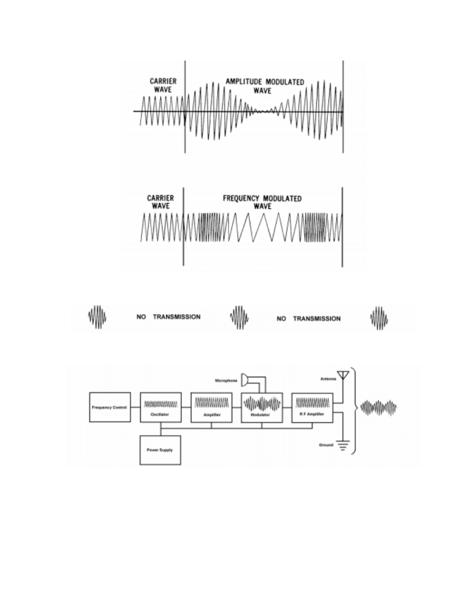
In amplitude modulation (AM) the amplitude of the
carrier wave is altered in accordance with the amplitude of
a modulating wave, usually of audio frequency, as shown in
Figure 1015a. In the receiver the signal is demodulated by
removing the modulating wave and converting it back to its
original form. This form of modulation is widely used in
voice radio, as in the standard broadcast band of commer-
cial broadcasting.
If the frequency instead of the amplitude is altered in
accordance with the amplitude of the impressed signal, as
shown in Figure 1015a, frequency modulation (FM) oc-
curs. This is used for commercial FM radio broadcasts and
the sound portion of television broadcasts.
Pulse modulation (PM) is somewhat different, there
being no impressed modulating wave. In this form of trans-
mission, very short bursts of carrier wave are transmitted,
separated by relatively long periods of “silence,” during
which there is no transmission. This type of transmission,
illustrated in Figure 1015b, is used in some common radio
navigational aids, including radar and Loran-C.
1016. Transmitters
A radio transmitter consists essentially of (1) a power
supply to furnish direct current, (2) an oscillator to convert
direct current into radio-frequency oscillations (the carrier
wave), (3) a device to control the generated signal, and (4)
an amplifier to increase the output of the oscillator. For
some transmitters a microphone is needed with a modulator
and final amplifier to modulate the carrier wave. In addi-
tion, an antenna and ground (for lower frequencies) are
needed to produce electromagnetic radiation. These com-
ponents are illustrated diagrammatically in Figure 1016.
1017. Receivers
When a radio wave passes a conductor, a current is in-
duced in that conductor. A radio receiver is a device which
senses the power thus generated in an antenna, and trans-
forms it into usable form. It is able to select signals of a
single frequency (actually a narrow band of frequencies)
from among the many which may reach the receiving an-
tenna. The receiver is able to demodulate the signal and
provide adequate amplification. The output of a receiver
RADIO WAVES
173
may be presented audibly by earphones or loudspeaker; or
visually on a dial, cathode-ray tube, counter, or other dis-
play. Thus, the useful reception of radio signals requires
three components: (1) an antenna, (2) a receiver, and (3) a
display unit.
Radio receivers differ mainly in (1) frequency range,
the range of frequencies to which they can be tuned; (2) se-
lectivity, the ability to confine reception to signals of the
desired frequency and avoid others of nearly the same fre-
quency; (3) sensitivity, the ability to amplify a weak signal
to usable strength against a background of noise; (4) stabil-
ity, the ability to resist drift from conditions or values to
which set; and (5) fidelity, the completeness with which the
essential characteristics of the original signal are repro-
duced. Receivers may have additional features such as an
automatic frequency control, automatic noise limiter, etc.
Some of these characteristics are interrelated. For in-
stance, if a receiver lacks selectivity, signals of a frequency
Figure 1015a. Amplitude modulation (upper figure) and frequency modulation (lower figure) by the same modulating wave.
Figure 1015b. Pulse modulation.
Figure 1016. Components of a radio transmitter.

174
RADIO WAVES
differing slightly from those to which the receiver is tuned
may be received. This condition is called spillover, and the
resulting interference is called crosstalk. If the selectivity is
increased sufficiently to prevent spillover, it may not permit
receipt of a great enough band of frequencies to obtain the
full range of those of the desired signal. Thus, the fidelity
may be reduced.
A transponder is a transmitter-receiver capable of ac-
cepting the challenge of an interrogator and automatically
transmitting an appropriate reply.
U.S. RADIONAVIGATION POLICY
1018. The Federal Radionavigation Plan
The Federal Radionavigation Plan (FRP) is produced
by the U.S. Departments of Defense and Transportation. It
establishes government policy on electronic navigation sys-
tems, ensuring consideration of national interests and
efficient use of resources. It presents an integrated Federal
plan for all common-use civilian and military Radionaviga-
tion systems, outlines approaches for consolidation of
systems, provides information and schedules, defines and
clarifies new or unresolved issues, and provides a focal point
for user input. The FRP is a review of existing and planned
radionavigation systems used in air, space, land, and marine
navigation. It is available from the National Technical Infor-
mation Service, Springfield, Virginia, 22161.
The first edition of the FRP was released in 1980 as
part of a Presidential report to Congress. It marked the first
time that a joint Department of Transportation/Department
of Defense plan had been developed for systems used by
both departments. The FRP has had international impact on
navigation systems; it has been distributed to the Interna-
tional Maritime Organization (IMO), the International Civil
Aviation Organization (ICAO), the International Associa-
tion of Lighthouse Authorities (IALA), and other
international organizations.
During a national emergency, any or all of the systems
may be discontinued due to a decision by the National
Command Authority (NCA). The NCA’s policy is to con-
tinue to operate radionavigation systems as long as the U.S.
and its allies derive greater benefit than adversaries. Oper-
ating agencies may shut down systems or change signal
formats and characteristics during such an emergency.
The plan is reviewed continually and updated biennial-
ly. Industry, advisory groups, and other interested parties
provide input. The plan considers governmental responsi-
bilities for national security, public safety, and
transportation system economy. It is the official source of
radionavigation systems policy and planning for the United
States. Systems covered by the FRP include, Radiobeacons,
Omega, TACAN, MLS, GPS, Loran C, VOR/VOR-DME/
VORTAC, ILS, and Transit.
1019. Individual System Plans
In order to meet both civilian and military needs, the
federal government has established a number of different
navigation systems. Each system utilized the latest technol-
ogy available at the time of implementation and has been
upgraded as technology and resources permitted. The FRP
addresses the length of time each system should be part of
the system mix. The 1992 FRP sets forth the following sys-
tem policy guidelines:
RADIOBEACONS: Both maritime and aeronautical
radiobeacons provide the civilian community with a low-
cost, medium accuracy navigation system. They will re-
main part of the radionavigation mix at least until the year
2000. Those radiobeacons suitable for supporting Differen-
tial GPS (DGPS) will remain well into the next century.
Many of the remaining maritime radiobeacons may be dis-
continued after the year 2000.
LORAN C: Loran C provides navigation, location, and
timing services for both civil and military air, land, and sea
users. It is the federally provided navigation system for the
maritime Coastal Confluence Zone; it is also a supplemental
air navigation system. The Loran C system serving the con-
tinental U.S., Alaska, and coastal areas with the exception of
Hawaii, is expected to remain in place through the year
2015. Military requirements for Loran C ended in 1994, and
U.S.-maintained stations overseas and in Hawaii will be
phased out. Discussions between the U.S. and foreign gov-
ernments may result in continuation of certain overseas
stations after termination of the military requirements.
OMEGA: Omega serves civilian and military mari-
time and air navigation. The military requirement for
Omega ended in 1994; the system may be maintained for
civil users at least until the year 2005. Replacement of
equipment at some stations may result in disruption or re-
duction of service in some areas. Also, the Omega system
relies on support from several foreign nations whose coop-
eration may not be forthcoming
TRANSIT: The Transit satellite system will end oper-
ations in December 1996.
GPS: The Global Positioning System, or GPS, will be
the military’s primary radionavigation system well into the
next century. It is operated by the U.S. Air Force, and it will
provide two basic levels of positioning service.
Standard Positioning Service (SPS) is a positioning and

RADIO WAVES
175
timing service which will provide horizontal positioning accu-
racies of 100 meters (2 drms, 95% probability) and 300 meters
(99.99% probability). Precise Positioning Service (PPS) will
provide extremely accurate positioning to only military users.
DIFFERENTIAL GPS: DGPS services are planned
by several DOT agencies to enhance civilian navigation
without reliance on the PPS. The Coast Guard operates ma-
rine DGPS in U.S. coastal waters. DGPS is a system in
which differences between observed and calculated GPS
signals are broadcast to users using marine radiobeacons.
The Coast Guard is implementing DGPS service in all U.S.
coastal waters, beginning with important ports and harbors,
to include Hawaii and the Great Lakes. It will provide 4-20
meter continuous accuracy.
A Memorandum of Agreement between DOD and
DOT for radionavigation planning became effective in
1979. It was updated in 1984 and again in 1990. This agree-
ment recognizes the joint responsibility of both agencies to
provide cost-effective navigation systems for both military
and civilian users, and requires the cooperation of both
agencies in navigation systems planning.
Many factors influence the choice of navigation sys-
tems, which must satisfy an extremely diverse group of users.
International agreements must be honored. The current in-
vestment in existing systems by both government and users
must be considered. The full life-cycle cost of each system
must be considered. No system will be phased out without
consideration of all these factors. The FRP recognizes that-
GPS may not meet the needs of all users; therefore, some
systems are currently being evaluated independently of GPS.
When GPS is fully implemented and evaluated, a further re-
view will determine which systems to retain and which to
phase out. The goal is to meet all military and civilian re-
quirements with the minimum number of systems.
The Departments of Defense and Transportation continual-
ly evaluate the components which make up the federally
provided and maintained radionavigation system. Several fac-
tors influence the decision on the proper mix of systems; cost,
military utility, accuracy requirements, and user requirements all
drive the problem of allocating scarce resources to develop and
maintain marine navigation systems. The lowering cost and in-
creasing accuracy of the Global Positioning System increase its
attractiveness as the primary navigation method of the future for
both military and civilian use. However, the popularity of GPS
with navigation planners masks the fact that it is still much more
expensive to the user than other radionavigation systems such as
loran and omega, and many civilian mariners may balk at the
cost of conversion. Planners’ uncertainties over the future of the
older navigation systems, especially in a time of shrinking re-
sources, will contribute to the uncertainty which will mark the
next five years in radionavigation planning and development.
RADIO DIRECTION FINDING
1020. Introduction
Medium frequency radio direction finders on board
vessels enable measurement of the bearings of marine ra-
diobeacons, aeronautical radiobeacons, and some
commercial radio stations. This is the simplest use of radio
waves in navigation.
Depending upon the design of the radio direction find-
er (RDF), the bearings of the radio transmissions are
measured as relative bearings, or as both relative and true
bearings. In one design, the true bearing dial is manually set
with respect to the relative bearing dial, in accordance with
the ship’s heading. In another design, the true bearing dial
is rotated electrically in accordance with a course input
from the gyrocompass.
Radiobeacons established primarily for mariners are
known as marine radiobeacons; beacons established pri-
marily for airmen are known as aeronautical
radiobeacons; other beacons established for both classes of
user are sometimes known as aeromarine radiobeacons.
The most common type of marine radiobeacon transmits ra-
dio waves of approximately uniform strength in all
directions. These omnidirectional beacons are known as
circular radiobeacons.
Except for calibration, radiobeacons operate continu-
ously, regardless of weather conditions.
Simple combinations of dots and dashes are used for
station identification. Where applicable, the Morse equiva-
lent character or characters are shown in conjunction with
the station characteristic. All radiobeacons superimpose the
characteristic on a carrier wave which is on continuously
during the period of transmission. This extends the useful-
ness of marine radiobeacons to an airborne or marine user
of an automatic radio direction finder (ADF). Users of the
“aural null” type radio direction finder notice no change. A
10-second dash is incorporated in the characteristic signal
to enable the user of the aural null type of radio direction
finder to refine the bearing.
Aeronautical radiobeacons are sometimes used by ma-
rine navigators for determining lines of position when
marine radiobeacons are not available. Since it is not possi-
ble to predict the extent to which land effect may render the
bearings of these beacons unreliable, they are not included
in Pub. 117, Radio Navigational Aids unless they are within
the marine frequency band and they are close enough to the
coast to have negligible land effect. Their inclusion in Pub.
117 does not imply that the beacons have been found reli-
able for marine use.

176
RADIO WAVES
1021. Using Radio Direction Finders
Direction bearing measurement at the receiver is ac-
complished with a directional antenna. Nearly all antennas
have some directional properties, but in the usual antenna
used for radio communication, these properties are not suf-
ficiently critical for navigational use.
Simple small craft RDF units usually have a ferrite rod
antenna mounted directly on a receiver, with a 360
°
gradu-
ated scale. The rod can be rotated to the null and a reading
taken off the scale, which is preset to either the boat’s course
or true north, according the navigator’s wishes. Some small
craft RDFs have a portable hand-held combination ferrite
rod and compass, with earphones to hear the null.
Two types of loop antenna are used in larger radio di-
rection finders. In one of these, the crossed loop type, two
loops are rigidly mounted in such manner that one is placed
at 90
°
to the other. The relative output of the two antennas is
related to the orientation of each with respect to the direction
of travel of the radio wave, and is measured by a device
called a goniometer. This is the type antenna used in an au-
tomatic direction finder. In the other variation, the rotating
loop type, a single loop is kept in rapid rotation by means of
a motor. The antenna output is shown on a cathode-ray tube,
and the resulting display shows the direction of the signal.
1022. Errors of Radio Bearings
Bearings obtained by radio direction finder are subject
to certain errors:
Quadrantal error: When radio waves arrive at a re-
ceiver, they are influenced somewhat by the immediate
environment. An erroneous bearing results from currents
induced in the direction finder antenna by re-radiation from
the structural features of the vessel’s superstructure and dis-
tortion of the radio wave front due to the physical
dimensions and contour of the vessel’s hull. This quadran-
tal error is a function of the relative bearing, normally being
maximum for bearings broad on the bow and broad on the
quarter. Its value for various bearings can be determined,
and a calibration table made.
Coastal refraction: A radio wave crossing a coastline
at an oblique angle undergoes a change of direction due to
differences in conducting and reflecting properties of land
and water. This is sometimes called land effect. It is avoided
by not using, or regarding as of doubtful accuracy, bearings
of waves which cross a shoreline at an oblique angle. Bear-
ings making an angle of less than 15
°
to 20
°
with a shoreline
should not be trusted. If the transmitter is near the coast, neg-
ligible error is introduced because of the short distance the
waves travel before undergoing refraction.
Polarization error: The direction of travel of radio
waves may undergo an alteration during the confused peri-
od near sunrise or sunset, when great changes are taking
place in the ionosphere. This error is sometimes called night
effect. The error can be minimized by averaging several
readings, but any radio bearings taken during this period
should be considered of doubtful accuracy.
Reciprocal bearings: Unless a radio direction finder has
a vertical sensing wire, there is a possible 180
°
ambiguity in
the reading. If such an error is discovered, one should take the
reciprocal of the uncorrected reading, and apply the correction
for the new direction. If there is doubt as to which of the two
possible directions is the correct one, one should wait long
enough for the bearing to change appreciably and take another
reading. The transmitter should draw aft between readings. If
the reciprocal is used, the station will appear to have drawn for-
ward. A reciprocal bearing furnished by a direction finder
station should not be used because the quadrantal error is not
known, either on the given bearing or its reciprocal.
1023. Accuracy Of Radio Bearings
In general, good radio bearings should not be in error
by more than 2
°
for distances under 150 nautical miles.
However, conditions vary considerably, and skill is an im-
portant factor. By observing the technical instructions for
the equipment and practicing frequently when results can
be checked by visual observation or by other means, one
can develop skill and learn to what extent radio bearings
can be relied upon under various conditions.
Other factors affecting accuracy include range, the
condition of the equipment, and the accuracy of the calibra-
tion. Errors in bearing can result if the selectivity of a radio
direction finder is poor.
1024. Factors Affecting Maximum Range
The service range of a radiobeacon is determined by the
strength of the radiated signal. Field strength requirements
for a given service range vary with latitude, being higher in
the southern latitudes. The actual useful range may vary con-
siderably from the service range with different types of radio
direction finders and during varying atmospheric conditions.
Sensitivity is a measure of the ability of a receiver to
detect transmissions. The sensitivity of a radio direction
finder determines the degree to which the full range capa-
bility of the radiobeacon system can be utilized.
Selectivity is a measure of the ability of a receiver to
choose one frequency and reject all others. Selectivity var-
ies with the type of receiver and its condition.
1025. Using RDF Bearings
Due to the many factors which enter into the transmis-
sion and reception of radio signals, a mariner cannot
practically estimate his distance from a radiobeacon either
by the strength of the signals received or by the time at
which the signals were first heard.
By setting the ship’s head toward the null, the naviga-
tor can steer toward the transmitter, and this is the most

RADIO WAVES
177
common use of RDFs today. In reduced visibility it is un-
wise to head directly toward the station unless there is
certain sea room. Soundings should be watched carefully
when homing, and a good lookout should be kept.
Alternatively, bearings can be taken on two or more
stations and the lines plotted to determine a fix. A single
RDF bearing can, of course, be crossed with any other LOP.
An RDF bearing crossed with a sounding curve can give a
rough position in the absence of any other systems. For
emergency use, an ordinary transistor radio tuned to a com-
mercial station can provide a rough bearing if the location
of the transmitter is known.
Before taking bearings on a commercial broadcasting
station, the mariner should consider the following, all of
which lead to errors:
1. The frequency of the commercial station may differ
widely from the frequency for which the radio di-
rection finder is calibrated.
2. The antenna may be remote from the broadcast
station.
3. The commercial stations are usually inland.
Accordingly, the use of commercial broadcasting sta-
tions to obtain a direction finder bearing is not
recommended for accurate navigation. If these stations are
used, the mariner should recognize the limitations of the
bearings obtained.
1026. Radio Direction Finder Stations
Radio direction finder stations are equipped with special
apparatus to determine the direction of radio signals transmit-
ted by ships. Many are for use only in emergencies, and none
are now located in the U.S. See Pub. 117, Radio Navigation-
al Aids, for a current worldwide list of RDF stations.

Document Outline
- Chapter 10
- Radio Waves
- Electromagnetic Wave Propagation
- 1000 . Source Of Radio Waves
- 1001 . Radio Wave Terminology
- 1002 . Electromagnetic Spectrum
- 1003 . Polarization
- 1004 . Reflection
- 1005 . Refraction
- 1006 . The Ionosphere
- 1007 . The Ionosphere And Radio Waves
- 1008 . Diffraction
- 1009 . Absorption And Scattering
- 1010 . Noise
- 1011 . Antenna Characteristics
- 1012 . Range
- 1013 . Radio Wave Propagation
- 1014 . Regulation Of Frequency Use
- 1015 . Types Of Radio Transmission
- 1016 . Transmitters
- 1017 . Receivers
- U.S. Radionavigation Policy
- Radio Direction Finding
- Electromagnetic Wave Propagation
- Radio Waves
Wyszukiwarka
Podobne podstrony:
Swanwick Radio Waves
Radio Waves Michael Swanwick
Radio Waves Michael Swanwick
radio jako medium audialne
radio i sport
Instrukcja radio Gamma V PL
Bmw 01 94 Business Mid Radio Owners Manual
zestawy radio
RADIO HELLO
Radio USG cw
checklist radio tv theatre events
Heathkit Basic Electricity Course (Basic radio Pt 2) ek 2b WW
CHAPT14 IBS
ar 156 radio 60360686 04 2001
radio WB, DIKS, ZSM
Pytania z radio 2008-2009, radiologia
II Rok Wydzial Lekarsko-Stomatologiczny, 3 rok stoma, radio
to sa pytania z radio od grupy ktora dzis pisala, stoma 4 rok, Radiologia stomatologiczna
więcej podobnych podstron