Politechnika Warszawska, Wydział Inżynierii Produkcji, Instytut Technologii Maszyn
Część 5
Pętla for, przebiegi
czasowe, struktury,
wzory
PRZYRZĄDY
PRZYRZĄDY
WIRTUALNE
WIRTUALNE
prof. dr hab. Krzysztof Jemielniak
k.jemielniak@wip.pw.edu.pl
http://www.cim.pw.edu.pl/kjemiel
ST 149, tel. 660 8656
http://www.cim.pw.edu.pl/labview
Warszawa, 2003
Politechnika Warszawska, Wydział Inżynierii Produkcji, Instytut Technologii Maszyn
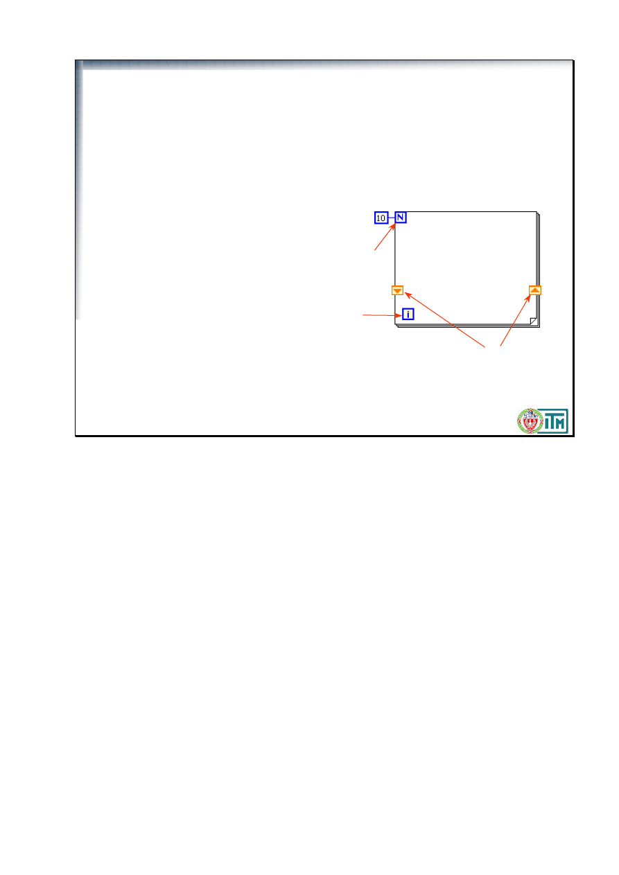
Pętla For
Wykonuje diagram wewnątrz
pętli zadaną liczbę razy
Terminal zadanej liczby przebiegów
(wejście numeryczne)
Licznik iteracji (wyjście numeryczne)
podaje liczbę wykonanych iteracji,
poczynając od 0 (tu 0..9)
Można dodać rejestry przesuwne, jeśli
potrzebne jest przekazywanie wartości
jednej iteracji do następnej
For Loops
A For Loop, shown at left, executes a subdiagram a set number of times. The value in the count terminal (an
input terminal) represented by the N, indicates how many times to repeat the subdiagram. The iteration
terminal (an output terminal), shown at left, contains the number of completed iterations. The iteration count
always starts at zero. During the first iteration, the iteration terminal returns 0.
You can add shift registers if you need to retain values from one iteration to the next.
Difference between While Loops and For Loops:
While Loops run until a condition is met.
For Loops run a predetermined number of times.
Politechnika Warszawska, Wydział Inżynierii Produkcji, Instytut Technologii Maszyn
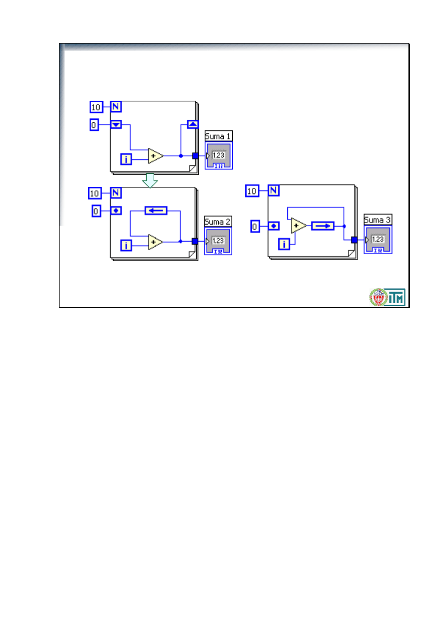
Węzeł sprzężenia zwrotnego
(Feedback Node)
45
45
Węzeł zawiera dane z
poprzedniej iteracji!
36
The Feedback Node, shown at left, appears automatically only in a For Loop or While Loop when you wire
the output of a subVI, function, or group of subVIs and functions to the input of that same VI, function, or
group. Like a shift register, the Feedback Node stores data when the loop completes an iteration, sends that
value to the next iteration of the loop, and transfers any data type. Use the Feedback Node to avoid
unnecessarily long wires in loops. The Feedback Node arrow indicates in which direction the data flows
along the wire.
You also can select the Feedback Node and place it only inside a For Loop or While Loop. If you place the
Feedback Node on the wire before you branch the wire that connects the data to the tunnel, the Feedback
Node passes each value to the tunnel. If you place the Feedback Node on the wire after you branch the wire
that connects data to the tunnel, the Feedback Node passes each value back to the input of the VI or function
and then passes the last value to the tunnel.
Politechnika Warszawska, Wydział Inżynierii Produkcji, Instytut Technologii Maszyn
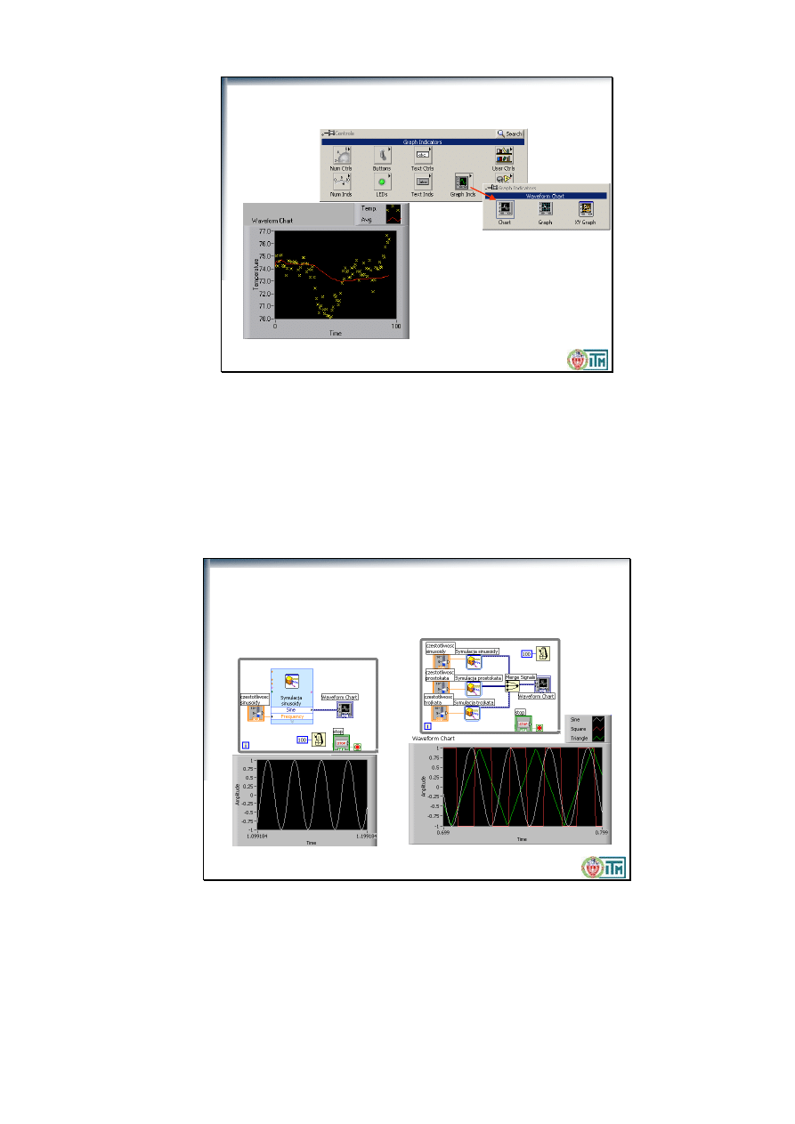
Przebiegi czasowe
(
Waveform Charts
)
Waveform Chart
– to specjalny
rodzaj wykresu służący do
wyświetlania przebiegu wartości
w czasie
The waveform chart is a special numeric indicator that displays one or more plots. The waveform chart is
located on the Controls»Graph Indicators palette. Waveform charts can display single or multiple plots.
The following front panel shows an example of a multi-plot waveform chart.
You can change the min and max values of either the x or y axis by double clicking on the value with the
labeling tool and typing the new value. Similarly, you can change the label of the axis. You can also right
click the plot legend and change the style, shape, and color of the trace that is displayed on the chart.
Politechnika Warszawska, Wydział Inżynierii Produkcji, Instytut Technologii Maszyn
Łączenie przewodów do przebiegów czasowych
Przebiegi pojedyncze
Przebiegi wielu zmiennych
You can wire a scalar output directly to a waveform chart to display one plot. To display multiple plots on
one chart, use the Merge Signals function found in the Functions >> Signal Manipulation palette. The
Merge Signal function bundles multiple outputs to plot on the waveform chart. To add more plots, use the
Positioning tool to resize the Merge Signal function.
The context help contains very good information on how the different ways to wire data into charts.
Politechnika Warszawska, Wydział Inżynierii Produkcji, Instytut Technologii Maszyn
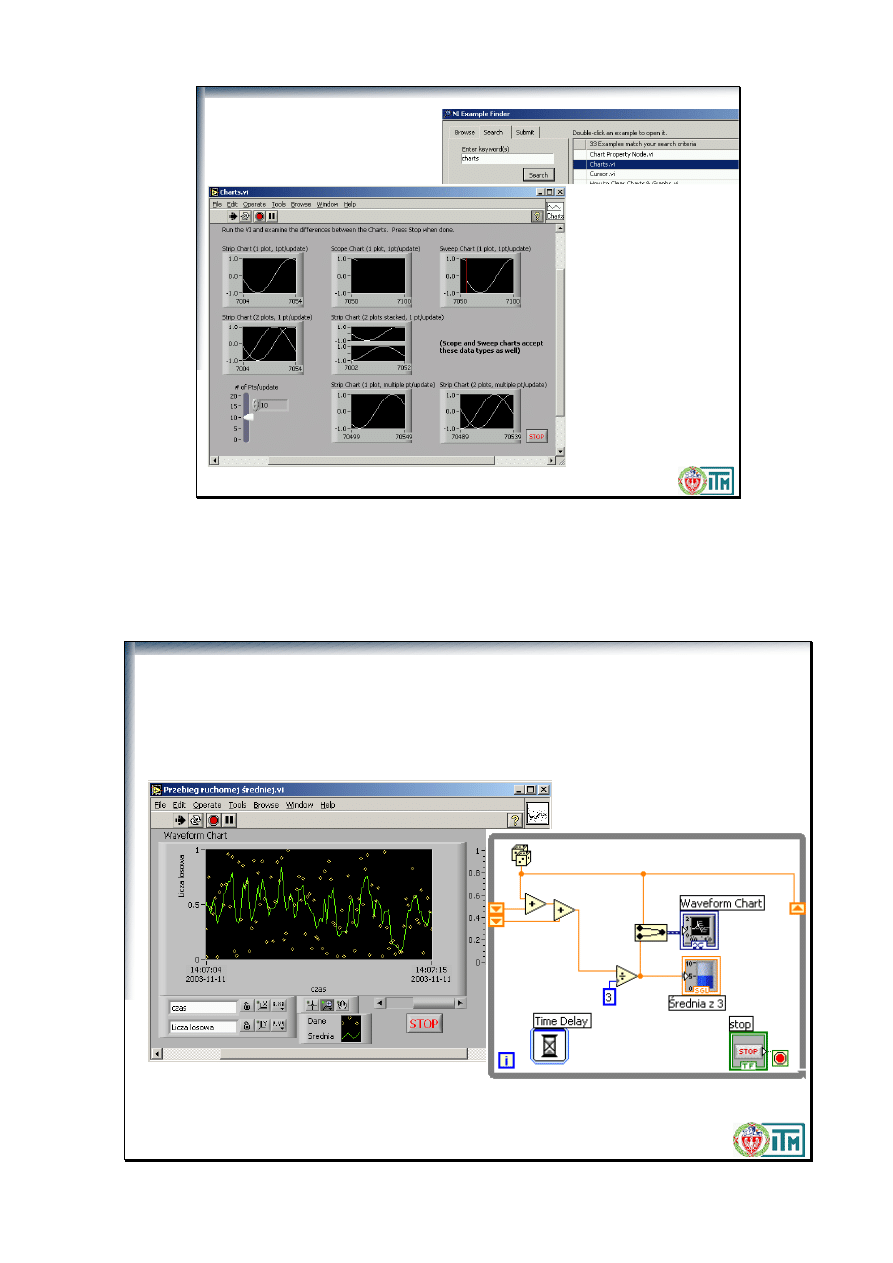
Charts – przykłady
This VI illustrates the different kinds of charts and the data types that they can accept. Charts can accept a
single point at a time or multiple points at a time. Also, charts can display multiple overlayed or stacked
plots. To change between strip, scope, and sweep update modes, right click on the chart and select
Advanced->Update Mode.
Politechnika Warszawska, Wydział Inżynierii Produkcji, Instytut Technologii Maszyn
Ćwiczenie:
Przebieg ruchomej średniej.VI
Zmodyfikuj
Ruchoma średnia.vi
tak, by widoczny by
ł
przebieg tej
średniej w czasie. Zapisz jako
Przebieg ruchomej średniej.vi
Politechnika Warszawska, Wydział Inżynierii Produkcji, Instytut Technologii Maszyn
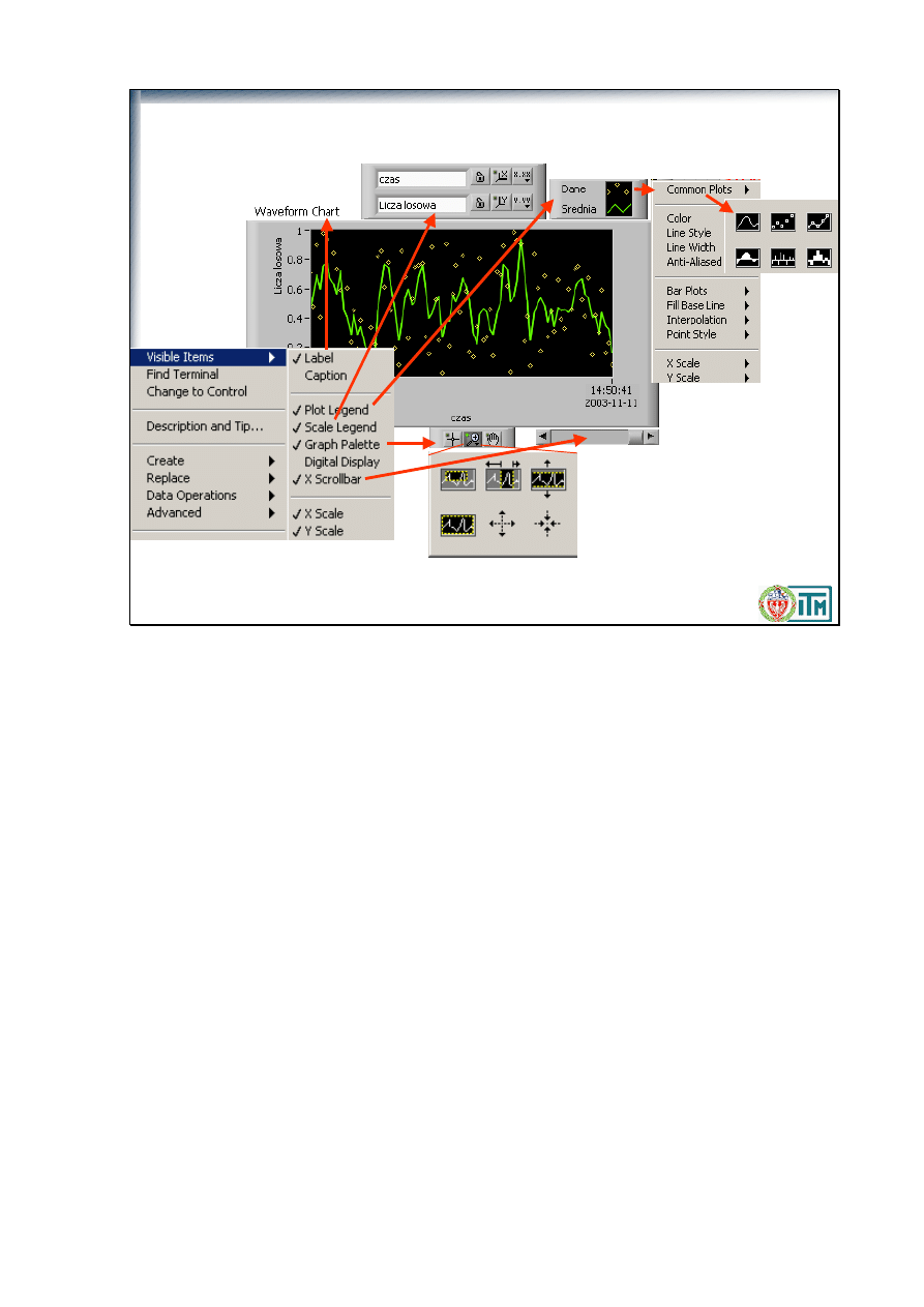
Dostosowywanie przebiegów czasowych
You can extensively customize charts and graphs.
Use the Show option in the pop-up menu to add Digital Displays for the traces, the Palette for the chart, and
Scroll Bars for the X axis.
You can change the font style and color for the axis labels by highlighting one of the numbers on the axis
you want to change with the Labeling tool and then choosing the style and color you want from the Text
menu.
Politechnika Warszawska, Wydział Inżynierii Produkcji, Instytut Technologii Maszyn
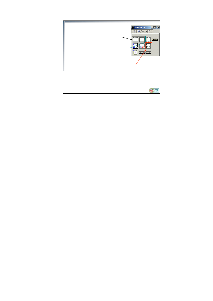
Struktury i wzory
• Struktura sekwencji (
Sequence structure
) —
zawiera jeden lub więcej podprogramów
wykonywanych kolejno
• Struktura warunkowa (
Case structure
) —zawiera
szereg podprogramów, z których wykonywany
jest tylko jeden – spełniający zadany warunek
• Węze
ł
wzorów (
Formula Node
) — wykonuje zaprogramowane
tekstowo operacje matematyczne w oparciu o podane na wejściach
wartości
Structures are graphical representations of the loops and case statements of text-based programming
languages. Use structures on the block diagram to repeat blocks of code and to execute code conditionally or
in a specific order.
Like other nodes, structures have terminals that connect them to other block diagram nodes, execute
automatically when input data are available, and supply data to output wires when execution completes.
Each structure has a distinctive, resizable border to enclose the section of the block diagram that executes
according to the rules of the structure. The section of the block diagram inside the structure border is called a
subdiagram. The terminals that feed data into and out of structures are called tunnels. A tunnel is a
connection point on a structure border.
Politechnika Warszawska, Wydział Inżynierii Produkcji, Instytut Technologii Maszyn
Struktury warunkowe
(
Case
)
•
Pozwala na alternatywne wykonanie fragmentów
programu zawartego w niej, w zależności od wartości
zmiennej sterującej
•
Zmienna sterująca może być
•
boolowska (prawda – fałsz)
•
tekstowa
•
numeryczna
•
Widoczny jest tylko jeden przypadek
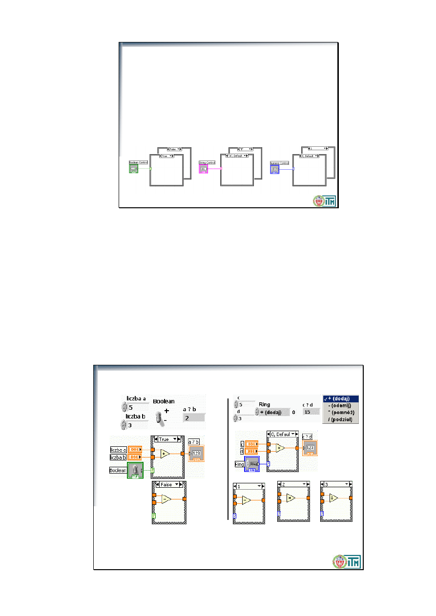
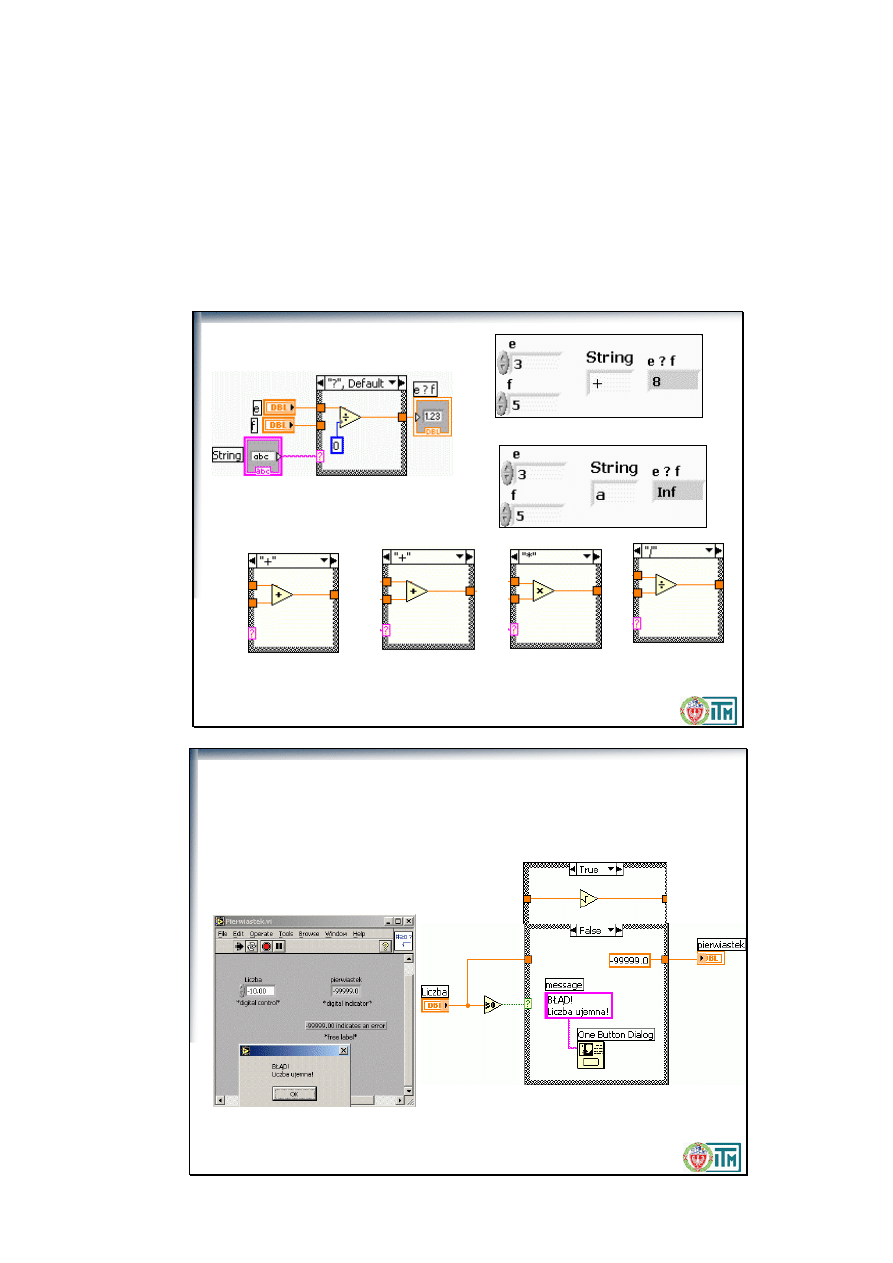
The Case structure allows you to choose a course of action depending on an input value.
Analogous to an if-then-else statement in other languages. Like a deck of cards. You can see only one case at
a time.
Example 1: Boolean input: Simple if-then case. If the Boolean input is TRUE, the true case will execute;
otherwise the FALSE case will execute.
Example 2: String input. Like the numeric input case, the value of the string determines which box to
execute. Stress that the value much match exactly or the structure will execute the default case.
Example 3: Numeric input. The input value determines which box to execute. If out of range of the cases,
LabVIEW will choose the default case.
Politechnika Warszawska, Wydział Inżynierii Produkcji, Instytut Technologii Maszyn
Warunki logiczne i numeryczne
Uwaga! Wszystkie możliwe przypadki muszą być „obsłużone”. Dla
zmiennych sterujących o możliwej większej niż „obsłużona” liczbie
przypadków, jeden musi być oznaczony jako domyślny
(
Default
)
Using the Text Ring from the List & Ring subpalette of the Controls palette.
Some of the features of Case structures:
Directly typing into the Cases
Setting ranges in the Case
Reordering the Cases
The Default Case
Politechnika Warszawska, Wydział Inżynierii Produkcji, Instytut Technologii Maszyn
Warunki tekstowe
Politechnika Warszawska, Wydział Inżynierii Produkcji, Instytut Technologii Maszyn
•Algorytm:
if (liczba >= 0) then
pierwiastek = SQRT (liczba)
else
pierwiastek = -99999
Wyświetl komunikat o błędzie
end if
Ćwiczenie:
Pierwiastek.VI
Politechnika Warszawska, Wydział Inżynierii Produkcji, Instytut Technologii Maszyn
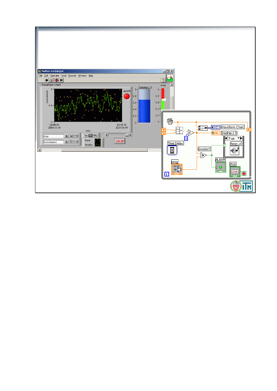
Zmodyfikuj
Przebieg ruchomej średniej.vi
tak, by przekroczenie zadanego
progu by
ł
o sygnalizowane zapaleniem czerwonej lampki (gdy sygna
ł
poniżej,
świeci na zielno) oraz sygna
ł
em dźwiękowym.
Zapisz jako
Nadzor sredniej.vi
.
Ćwiczenie:
Nadzór średniej.VI
Common questions:
Why do I need to place the Beep VI in a Case structure, but not the warning light? The warning light is
a Boolean indicator and registers whatever the Boolean condition is. The Beep VI requires no inputs; it
beeps when called.
Can I show all the cases of my diagram at once? Yes. Choose Preview under the Print Documentation
window of
the File menu.
Politechnika Warszawska, Wydział Inżynierii Produkcji, Instytut Technologii Maszyn
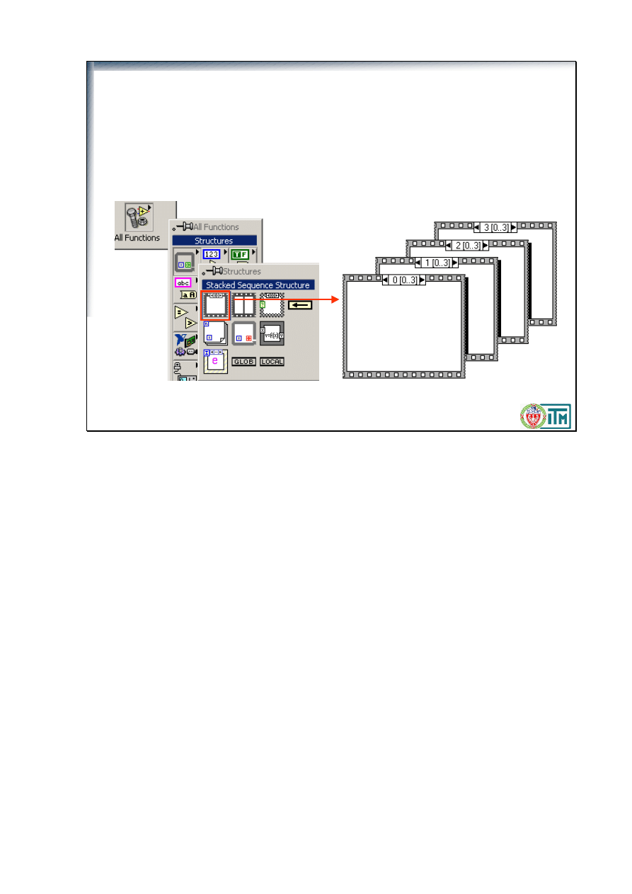
• Znajduje się na palecie
All Functions>Structures
• Wykonuje diagramy zawarte w ramkach
KOLEJNO
ramka po
ramce, jak klatki filmu (0..x), gdzie x – liczba ramek
• Ułożone jedna za drugą jak talia kart (
Stacked
), widoczna tylko
jedna (dowolna wybrana)
Struktura Sekwencji
(Sequence Structure)
In a text-based language, program statements execute in the order in which they appear. In data flow, a node
executes when data is available at all its input terminals.
Sometimes it is hard to tell the exact order of execution. Often, certain events must take place before other
events.
Sequence structure: Used to control the order in which nodes in a diagram will execute.
In the Structures subpalette.
Looks like a frame of film.
Used to execute diagrams sequentially.
Like a deck of cards. You can see only one frame at a time.
Politechnika Warszawska, Wydział Inżynierii Produkcji, Instytut Technologii Maszyn
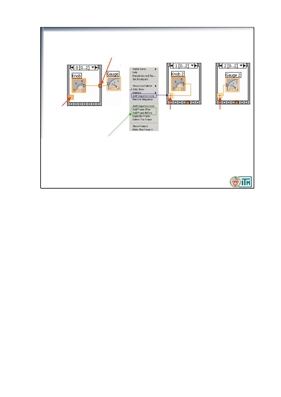
Terminal
stworzony w
ramce 1
Dane
niedostępne
w ramce 0
Przekazywanie danych w sekwencji
Do przekazywania danych między
ramkami (tylko w przód) służą terminale
lokalne sekwencji
(sequence local)
tworzone na brzegach ramek
(klik prawym
klawiszem).
Dane
dostępne
w ramce 2
Dodawanie ramek: klik
prawym klawiszem
Na zewnątrz sekwencji można przekazać dane z dowolnej ramki, jednak są
dostępne dopiero po zakończeniu całej sekwencji
You cannot directly wire data from one sequence frame to any another frame with the usual wiring
techniques.
Sequence locals are variables that pass data between frames of a Sequence structure.
Created on the border of the Sequence frame.
Data wired to a sequence local is available only in subsequent frames. It is not available in previous frames.
In subsequent frames, you can use a sequence local to output only. If you must read a value from a
sequence local, change it, and use it in a later frame, you must create another sequence local.
Applications for Sequence structures:
Benchmarking with DAQ counters (Start Timer, Run Benchmark, Stop Timer). DAQ counters are much
more accurate than the timers based on the computer clock.
Politechnika Warszawska, Wydział Inżynierii Produkcji, Instytut Technologii Maszyn
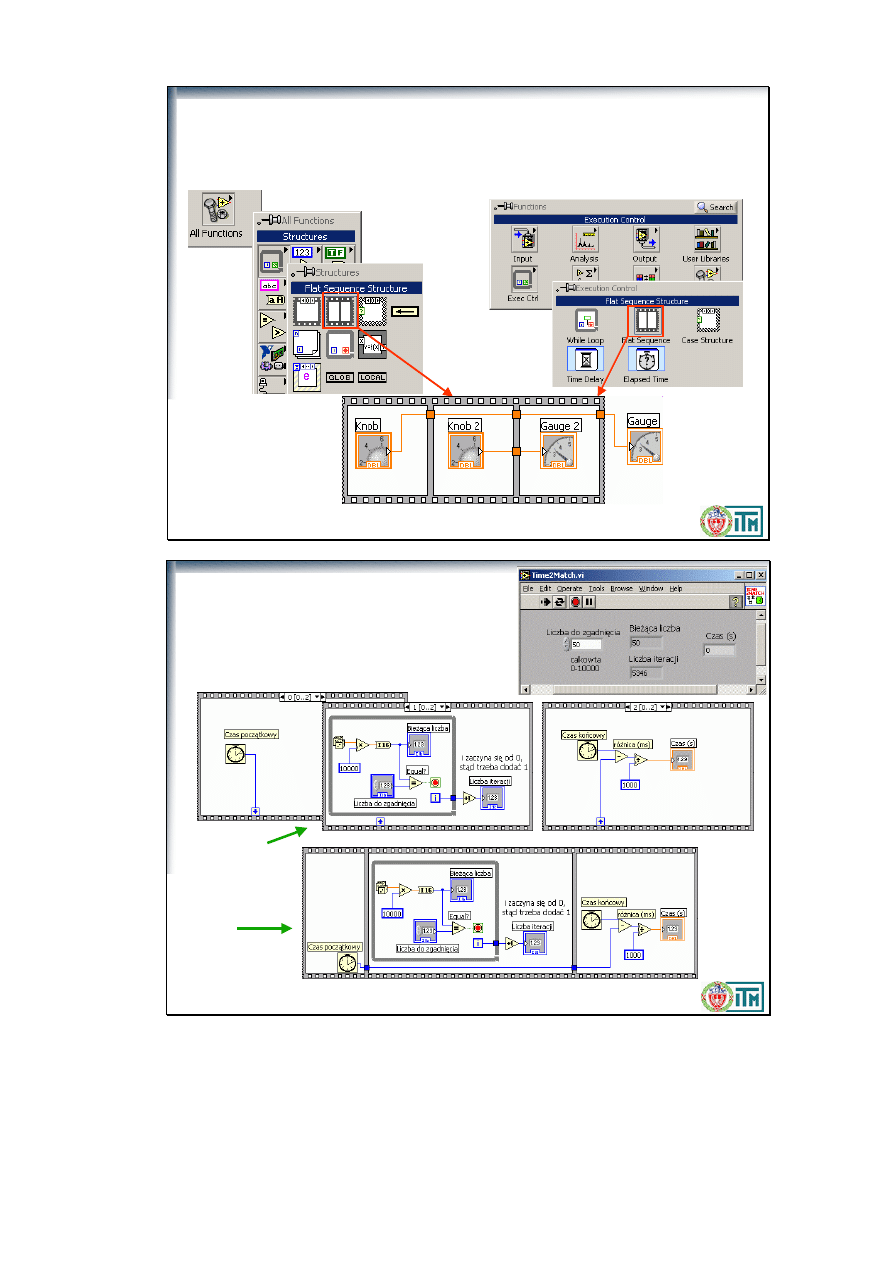
Struktura Sekwencji
(Sequence Structure)
Druga wersja (
Flat
), znajduje się także na palecie
Functions>Execution
Control.
Tu widoczne są wszystkie ramki jednocześnie.
Politechnika Warszawska, Wydział Inżynierii Produkcji, Instytut Technologii Maszyn
Ćwiczenie
Time2Match.vi
Zmodyfikuj
Auto Match.vi
tak by
wskazywał czas potrzebny na znalezienie
dopasowania. Zapisz jako
Time2Match.vi
Stacked
flat
lub
Common questions:
Why do I need to use a Sequence structure? Because you must start timing, find the match, and stop
timing, in that exact order. The Tick Count function does not have any inputs, so it will run immediately if
you do not use a Sequence structure.
Politechnika Warszawska, Wydział Inżynierii Produkcji, Instytut Technologii Maszyn
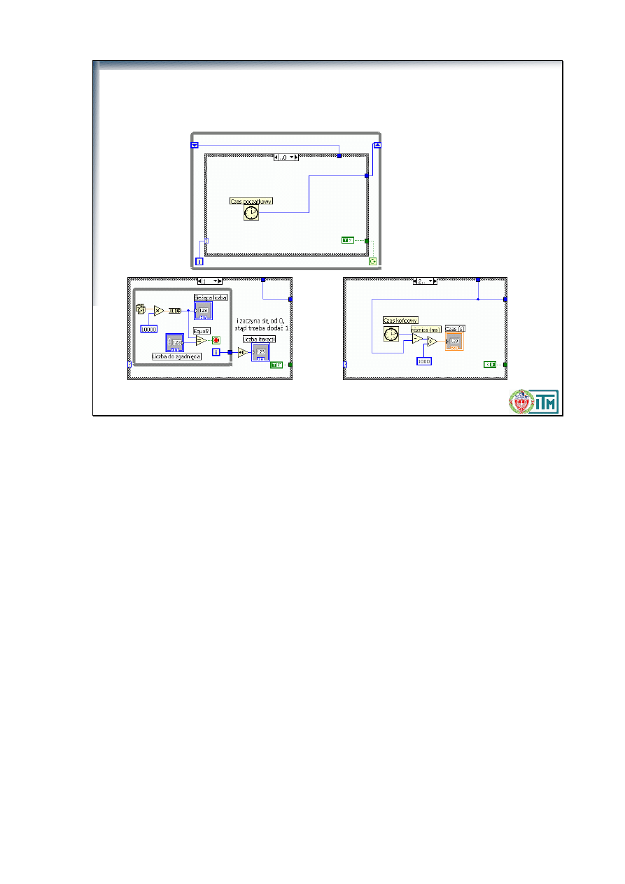
Zastępowanie sekwencji strukturą warunkową
Time2Match
w wersji warunkowej:
Politechnika Warszawska, Wydział Inżynierii Produkcji, Instytut Technologii Maszyn
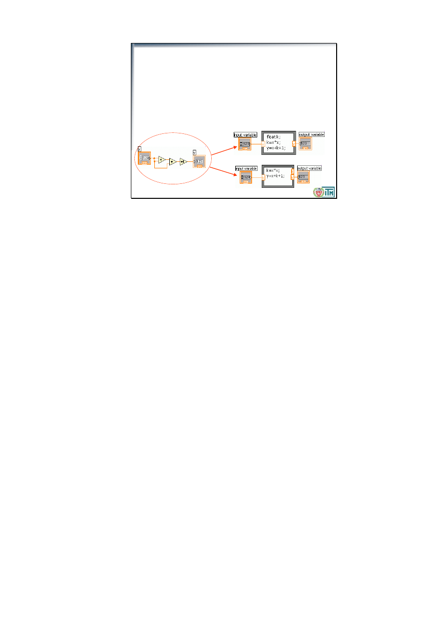
Węzeł wzorów
(
Formula Nodes)
•
Znajduje się na palecie
All Functions>Structures
•
Umożliwia wprowadzenie złożonych wzorów w trybie tekstowym
•
Zmienne wejściowe i wyjściowe tworzy się na brzegach
•
Zmienne pomocnicze tworzy się na brzegach lub deklaruje na
wstępie
•
Każdy wzór musi kończyć się średnikiem (;)
•
Help kontekstowy pokazuje dostępne funkcje
lub
Sometimes it is preferable to program mathematical expressions with text-based function calls, rather than
icons (which can take up a lot of room on the diagram).
Formula Node: allows you to implement complicated equations using text-based instructions.
Resizable box for entering algebraic formulas directly into block diagrams.
To add variables, right-click and choose Add Input or Add Output. Name variables as they are used in
formula. (Names are case sensitive.)
Statements must be terminated with a semicolon.
When using several formulas in a single formula node, every assigned variable (those appearing on the left
hand side of each formula) must have an output terminal on the formula node. These output terminals do not
need to be wired, however.
Compare the examples on the slide.
When you work with variables, remember the following points:
• There is no limit to the number of variables or equations in a Formula Node.
• No two inputs and no two outputs can have the same name, but an output can have the same name as an
input.
• Declare an input variable by right-clicking the Formula Node border and selecting Add Input from the
shortcut menu. You cannot declare input variables inside the Formula Node.
• Declare an output variable by right-clicking the Formula Node border and selecting Add Output from the
shortcut menu. The output variable name must match either an input variable name or the name of a variable
you declare inside the Formula Node.
• You can change whether a variable is an input or an output by right-clicking it and selecting Change to
Input or Change to Output from the shortcut menu.
• You can declare and use a variable inside the Formula Node without relating it to an input or output wire.
• You must wire all input terminals.
• Variables can be floating-point numeric scalars, whose precision depends on the configuration of your
computer. You also can use integers and arrays of numerics for variables.
• Variables cannot have units.
Politechnika Warszawska, Wydział Inżynierii Produkcji, Instytut Technologii Maszyn
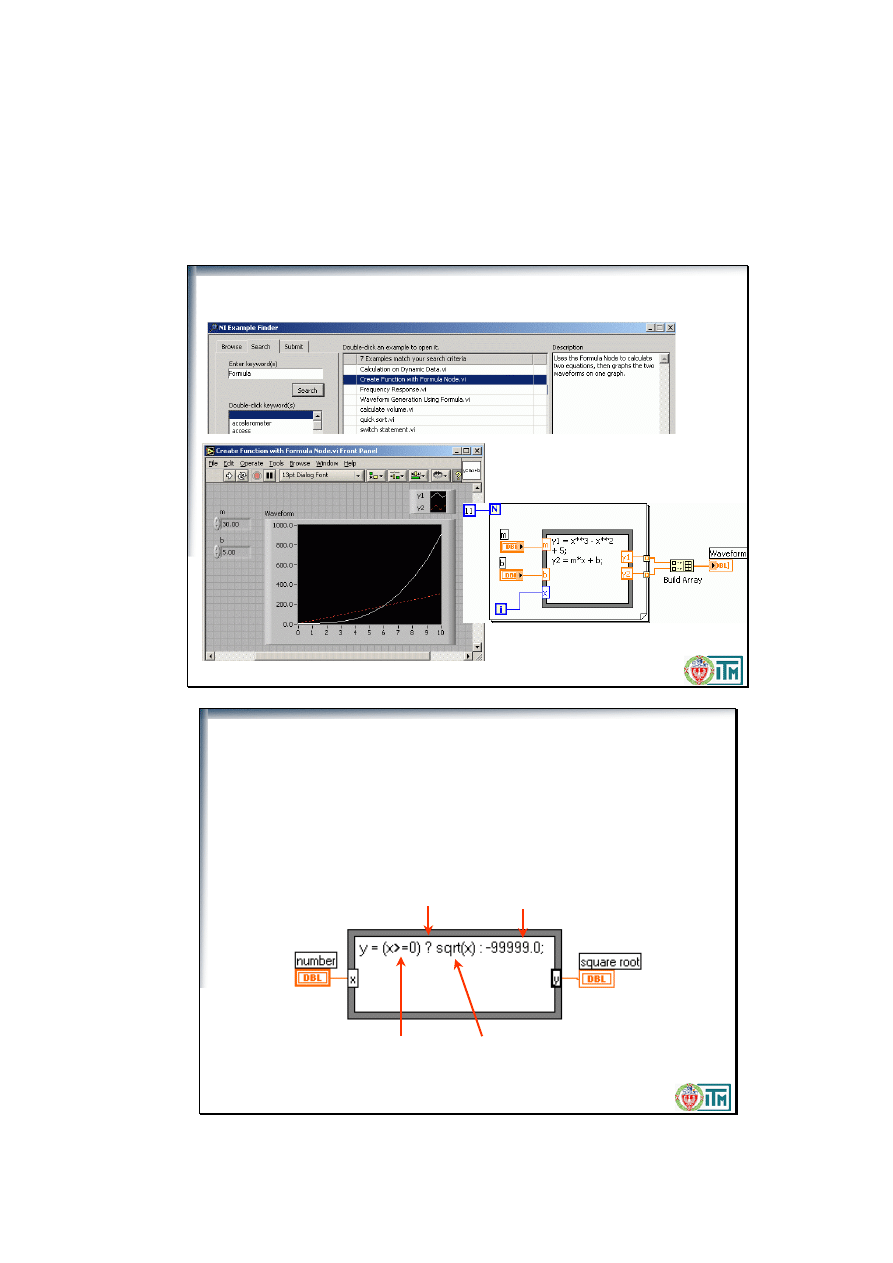
Przykłady zastosowania węzła wzorów
Politechnika Warszawska, Wydział Inżynierii Produkcji, Instytut Technologii Maszyn
warunek
Operator warunkowy
Wynik dla
prawda
Wynik dla
fałsz
Operacje warunkowe w węzłach wzorów
if (x >= 0) then
y = SQRT (x)
else
y = -99999
end if
Branching structure used for Formula Nodes is identical to the “?:” branching structure in C.
Politechnika Warszawska, Wydział Inżynierii Produkcji, Instytut Technologii Maszyn
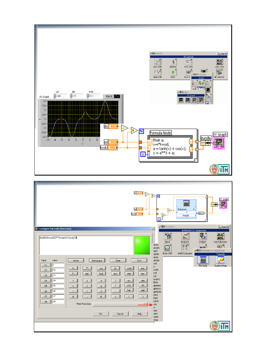
x
y
Ćwiczenie:
Wykres funkcji.VI
Opracuj program wykreślający przebieg dowolnej
funkcji zapisanej węźle wzorów, np.:
y = a
3
+ a;
gdzie
a = tanh(x) + cos(x);
w zadanym przedziale, z zadanym krokiem.
Wykorzystaj
XYGraph
z
All controls>Graph
a
3
-> a**3
Politechnika Warszawska, Wydział Inżynierii Produkcji, Instytut Technologii Maszyn
Express
Formula.vi
Umożliwia wykonanie obliczeń
jak na kalkulatorze naukowym
z 8-ma zmiennymi
wejściowymi
Patrz też przykład:
Moonlanding.vi
Politechnika Warszawska, Wydział Inżynierii Produkcji, Instytut Technologii Maszyn
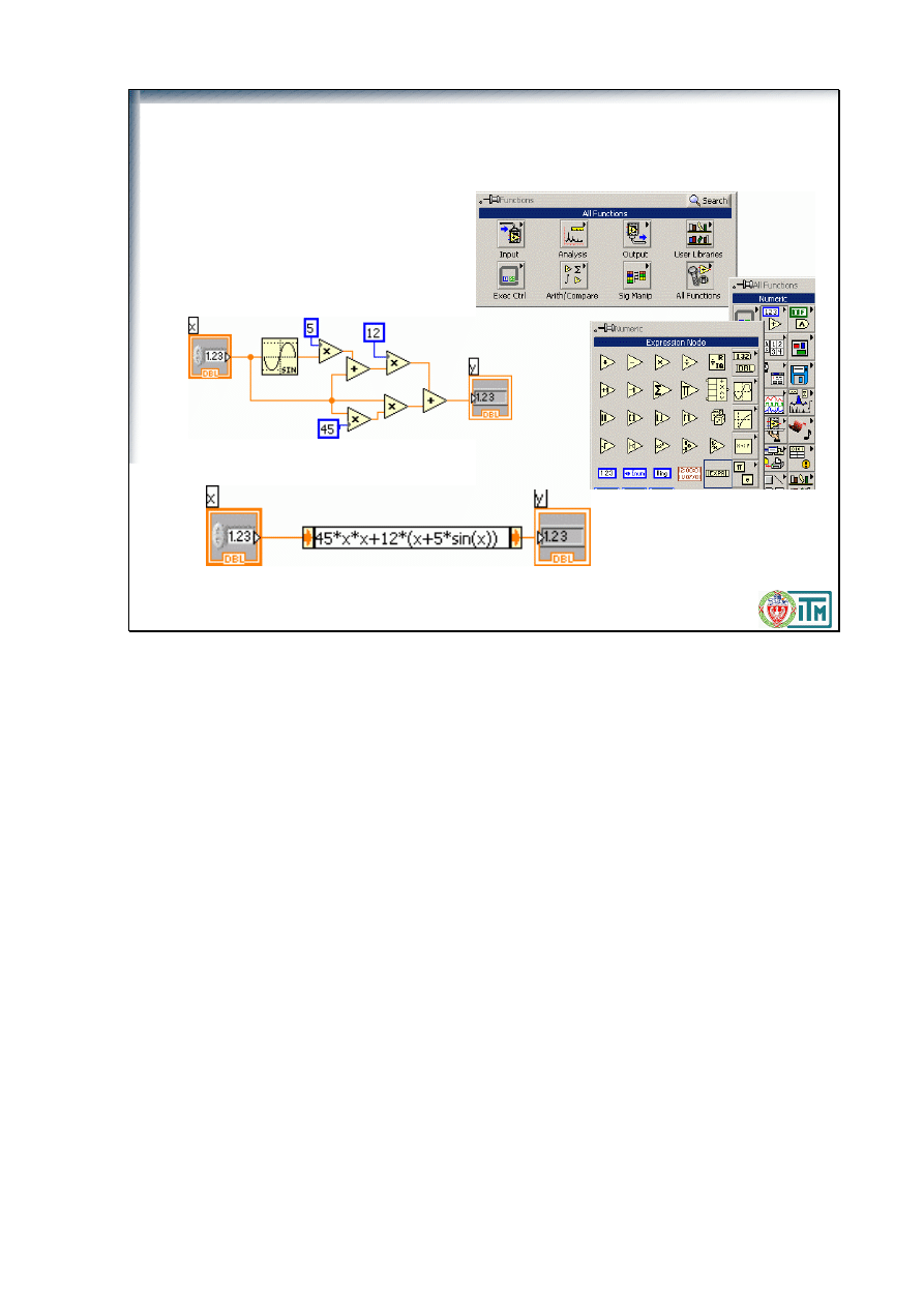
Węzeł wyrażenia
(Expression Node)
Przydatne do z
ł
ożonych wzorów z jedną zmienną, np.:
y=45*x
2
+12*(x+5*sin(x))
Zamiast z
ł
ożonego diagramu...
...można zastosować proste:
Use Expression Nodes to calculate expressions, or equations, that contain a single variable. Expression
Nodes are useful when an equation has only one variable, but is otherwise complicated.
Expression Nodes use the value you pass to the input terminal as the value of the variable. The output
terminal returns the value of the calculation.
Wyszukiwarka
Podobne podstrony:
5 Petla for, przebiegi czasowe, struktury, wzory
Petla For w C
silnik skokowy przebiegi czasowe
silnik bldc przebiegi czasowe
Analiza Struktury wzory
25 Zadań Pętla For
Kompleksowa analiza struktury wzory i wskazowki
silnik srm przebiegi czasowe
Ćw9 Pętla FOR, WHILE, REPEAT
wniosek o czasowe opuszczenie, Wzory pism
Badanie przebiegu czasowego e, Szkoła, Politechnika 1- 5 sem, SEM IV, Maszyny Elektryczne. Laborator
Badanie przebiegu czasowego a, Szkoła, Politechnika 1- 5 sem, SEM IV, Maszyny Elektryczne. Laborator
Badanie przebiegu czasowego b, Szkoła, Politechnika 1- 5 sem, SEM IV, Maszyny Elektryczne. Laborator
Turbo Pascal - pętla for Martunia, ETI Edukacja technicyno inf,, KONSPEKTY, Konspekty
pętla for
008 Pętla FOR
Badanie przebiegu czasowego d, Szkoła, Politechnika 1- 5 sem, SEM IV, Maszyny Elektryczne. Laborator
[lekcja 22] Pętla for Kurs C++ » Poziom 2
więcej podobnych podstron