
VLT
®
Drives and Controls
WINDER AND TENSION
CONTROL OPTION
VLT
®
Series 5000
MG.50.K2.02 - VLT is a registered Danfoss trademark
*MG50K202*
Introduction .................. page 3
Parameters ................... page 5
This manual is to be used for the Winder and Tension
Control Option installed in all VLT 5000 Series Frequency
Converters with software version 3.xx.
If the option is used in drives with a VLT 5000 software
version higher than 3.40, the functionality of the drive will
be that of software version 3.40.
This Winder and Tension Control Option has the software
version 13.10.
The software version number can be found in parameter
624.
VLT
®
5000 Series Winder Option
MG.50.K2.02 - VLT is a registered Danfoss trademark
2
■ Introduction
A wide range of material-processing machines use
tension control to provide a constant pull of a web or
wire through the machine in order to ensure consistent
product quality. The tension is typically measured by
means of a roller mounted on a dancer arm or a load
cell. Dancers are generally used where space is not a
problem, and load cells in applications where the space
is limited. In addition, dancer arms offer much more
Intr
oduction
control flexibility - particularly during transient conditions
like acceleration and deceleration. The tension is
created by a winder or a roller.
The web and wire processing applications are
typical for the metal, paper, textile, plastics, printing
and converting industries.
Danfoss has developed an integrated tension control
option for the VLT 5000 which offer an advanced
PID process controller with feed forward function.
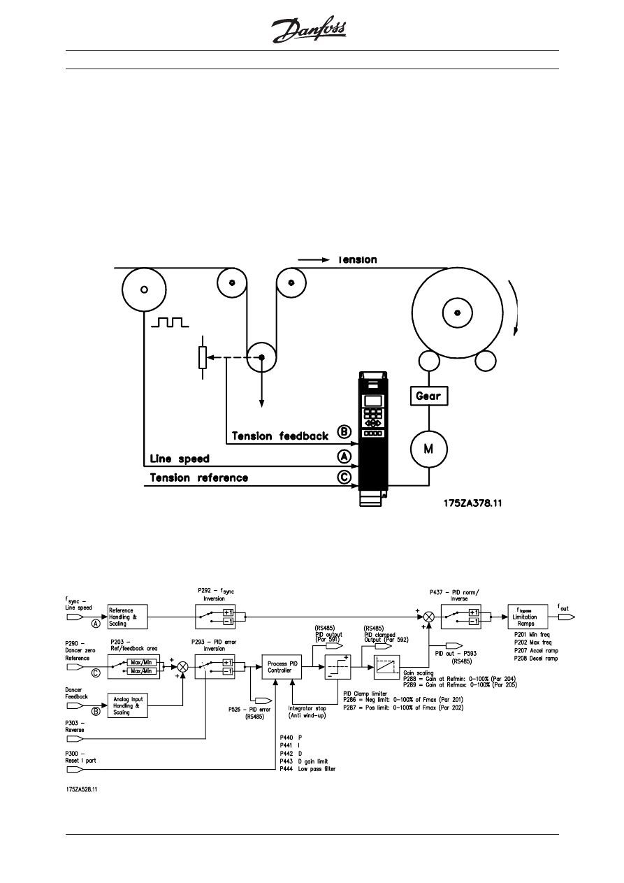
Description of the tension controller option
VLT
®
5000 Series Winder Option
3
MG.50.K2.02 - VLT is a registered Danfoss trademark
■ Features and Benefits
•
Consistent tension as a roll unwinds from full
roll to core or vice versa due to an advanced
PID controller with feed forward function.
In unwinding applications brake chopper and
brake resistor should be used. Alternatively
the DC links of the drives should be inter
connected ( load sharing ).
•
Consistent tension, even during splicing and
emergency stops as the tension feedback
compensates for inertia in the rollers.
•
User-friendly, fast commisioning and
adjustment: all variables are fully scalable and
the functions are programmable as normal or
inverse action.
•
Programmable dancer position as the zero
position is adjustable.
•
Reduced dancer oscillations due to adjustable
D-gain limit, PID low pass filter and PID clamp
limiter.
•
Dancer feedback action can be tailor-made
to the application due to scalable P-gain.
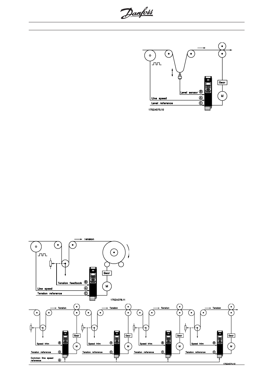
■ Typical Applications
The controller is primarily suitable for the following
applications:
➀ Constant tension surface winders.
➁ Draw applications with common line speed
and dancer speed trim.
➂ Tensionless speed control.
Description of the tension controller option
The tension controller is designed as a PID controller
with feed forward function. The line speed reference
signal is scalable and it is selectable as normal or
inverse action. The feedback signal for the PID
controller is scalable and the polarity of the feedback
signal is selectable. The PID controller allows limiting
the D-gain and a selectable PID low pass filter
dampens feedback oscillations. A PID anti wind-up
function freezes the integrator when reaching the limits
of the output frequency.
A PID clamp limiter makes it possible to clamp the
PID output to limit the action of the PID controller. The
proportional gain scaling makes the P-gain dependent
of the actual line speed. These features are useful to
dampen oscillations in applications with multiple dancer
systems in series.
■
Not suitable for center Winders - no compensation
for changing winder radius.
➀
➁
➂

VLT
®
5000 Series Winder Option
MG.50.K2.02 - VLT is a registered Danfoss trademark
4
✭ = factory setting. ( ) = display text [ ] = value for use in communication via serial communication port
009
Display line 2 (DISPLAY LINE 2)
Value:
Reference [%] (REFERENCE [%])
[1]
Reference [unit] (REFERENCE [UNIT])
[2]
Feedback [unit] (FEEDBACK [UNIT])
[3]
✭ Frequency [Hz] (FREQUENCY [Hz])
[4]
Frequency x Scaling [-] (FREQUENCY X SCALE) [5]
Motor current [A] (MOTOR CURRENT [A])
[6]
Torque [%] (TORQUE [%])
[7]
Power [kW] (POWER [kW])
[8]
Power [HP] (POWER [hp] [US])
[9]
Output energy [kWh] (OUTPUT ENERGY [kWh]) [10]
Motor voltage [V] (MOTOR VOLTAGE [V])
[11]
DC link voltage [V] (DC LINK VOLTAGE [V])
[12]
Thermal load, motor [%] (MOTOR THERMAL [%]) [13]
Thermal load, VLT [%] (VLT THERMAL [%])
[14]
Hours run [Hours] (RUNNING HOURS)
[15]
Digital input [Binary code] (DIGITAL INPUT [BIN]) [16]
Analogue input 53 [V] (ANALOG INPUT 53 [V]) [17]
Analogue input 54 [V] (ANALOG INPUT 54 [V]) [18]
Analogue input 60 [mA]
(ANALOG INPUT 60 [mA])
[19]
Pulse reference [Hz] (PULSE REF. [Hz])
[20]
External reference [%] (EXTERNAL REF [%])
[21]
Status word [Hex] (STATUS WORD [HEX])
[22]
Brake effect/2 min. [KW]
(BRAKE ENERGY/2 min)
[23]
Brake effect/sec. [kW]
(BRAKE ENERGY/s)
[24]
Heat sink temp. [°C] (HEATSINK TEMP [°C])
[25]
Alarm word [Hex] (ALARM WORD [HEX])
[26]
Control word [Hex] (CONTROL WORD [HEX])
[27]
Warning word 1 [Hex]
(WARNING WORD 1 [HEX])
[28]
Warning word 2 [Hex]
(WARNING WORD 2 [HEX])
[29]
W
W
W
W
Winder PID contr
inder PID contr
inder PID contr
inder PID contr
inder PID controller err
oller err
oller err
oller err
oller error
or
or
or
or
(PID ERR)
(PID ERR)
(PID ERR)
(PID ERR)
(PID ERR)
[30]
[30]
[30]
[30]
[30]
W
W
W
W
Winder PID contr
inder PID contr
inder PID contr
inder PID contr
inder PID controller output
oller output
oller output
oller output
oller output
(PID OUT)
(PID OUT)
(PID OUT)
(PID OUT)
(PID OUT)
[31]
[31]
[31]
[31]
[31]
PID clamped output
PID clamped output
PID clamped output
PID clamped output
PID clamped output
(PID clamped out)
(PID clamped out)
(PID clamped out)
(PID clamped out)
(PID clamped out)
[32]
[32]
[32]
[32]
[32]
PID line speed scaled output
PID line speed scaled output
PID line speed scaled output
PID line speed scaled output
PID line speed scaled output
(PID gainscaled out)
(PID gainscaled out)
(PID gainscaled out)
(PID gainscaled out)
(PID gainscaled out)
[33]
[33]
[33]
[33]
[33]
Function:
This parameter allows a choice of the data value to
be displayed in line 2 of the display.
Parameters 010-012 enable the use of three additio-
nal data values to be displayed in line 1.
Operation & Display
Description of choice:
Reference
Reference
Reference
Reference
Reference [%]
[%]
[%]
[%]
[%] corresponds to the total reference
(sum of digital/analogue/preset/bus/freeze ref./catch-
up and slow-down).
Reference
Reference
Reference
Reference
Reference [unit]
[unit]
[unit]
[unit]
[unit] gives the status value of terminals 17/
29/53/54/60 using the unit stated on the basis of
configuration in parameter 100 (Hz, Hz and rpm).
Feedback
Feedback
Feedback
Feedback
Feedback [unit]
[unit]
[unit]
[unit]
[unit] gives the status value of terminal 33/
53/60 using the unit/scale selected in parameter 414,
415 and 416.
Frequency
Frequency
Frequency
Frequency
Frequency [Hz]
[Hz]
[Hz]
[Hz]
[Hz] gives the motor frequency, i.e. the
output frequency from the VLT frequency converter.
Frequency x Scaling
Frequency x Scaling
Frequency x Scaling
Frequency x Scaling
Frequency x Scaling [-]
[-]
[-]
[-]
[-] corresponds to the present
motor frequency f
M
(without resonance dampening)
multiplied by a factor (scaling) set in parameter 008.
Motor current
Motor current
Motor current
Motor current
Motor current [A]
[A]
[A]
[A]
[A] states the phase current of the mo-
tor measured as effective value.
T
T
T
T
Torque
orque
orque
orque
orque [%]
[%]
[%]
[%]
[%] gives the current motor load in relation to
the rated motor torque.
Power
Power
Power
Power
Power [kW]
[kW]
[kW]
[kW]
[kW] states the actual power consumed by the
motor in kW.
Power
Power
Power
Power
Power [HP]
[HP]
[HP]
[HP]
[HP] states the actual power consumed by the
motor in HP.
Output energy
Output energy
Output energy
Output energy
Output energy [kWh]
[kWh]
[kWh]
[kWh]
[kWh] states the energy consumed by
the motor since the latest reset was made in parame-
ter 618.
Motor voltage
Motor voltage
Motor voltage
Motor voltage
Motor voltage [V]
[V]
[V]
[V]
[V] states the voltage supplied to the
motor.
DC link voltage
DC link voltage
DC link voltage
DC link voltage
DC link voltage [V]
[V]
[V]
[V]
[V] states the intermediate circuit volt-
age in the VLT frequency converter.
Thermal load, motor
Thermal load, motor
Thermal load, motor
Thermal load, motor
Thermal load, motor [%]
[%]
[%]
[%]
[%] states the calculated/
estimated thermal load on the motor. 100% is the
cut-out limit.
Thermal load, VL
Thermal load, VL
Thermal load, VL
Thermal load, VL
Thermal load, VLT
T
T
T
T [%]
[%]
[%]
[%]
[%] states the calculated/estimated
thermal load on the VLT frequency converter. 100% is
the cut-out limit.
Hours run
Hours run
Hours run
Hours run
Hours run [Hours]
[Hours]
[Hours]
[Hours]
[Hours] states the number of hours that the
motor has run since the latest reset in parameter 619.
Digital input
Digital input
Digital input
Digital input
Digital input [Binary code]
[Binary code]
[Binary code]
[Binary code]
[Binary code] states the signal states
from the 8 digital terminals (16, 17, 18, 19, 27, 29, 32
and 33) Input 16 corresponds to the bit at the far left.
'0' = no signal, '1' = connected signal.
Analogue input
Analogue input
Analogue input
Analogue input
Analogue input 53 [V]
53 [V]
53 [V]
53 [V]
53 [V] states the signal value on termi-
nal 53.
Analogue input
Analogue input
Analogue input
Analogue input
Analogue input 54 [V]
54 [V]
54 [V]
54 [V]
54 [V] states the signal value on termi-
nal 54.
Analogue input
Analogue input
Analogue input
Analogue input
Analogue input 60 [V]
60 [V]
60 [V]
60 [V]
60 [V] states the signal value on termi-
nal 60.
Pulse
Pulse
Pulse
Pulse
Pulse reference
reference
reference
reference
reference [Hz]
[Hz]
[Hz]
[Hz]
[Hz] states the possible frequency in Hz
connected to the terminals 17 or 29.
External reference
External reference
External reference
External reference
External reference [%]
[%]
[%]
[%]
[%] gives the sum of the external
reference as a percentage (the sum of analogue/
pulse/bus).
Status word
Status word
Status word
Status word
Status word [Hex]
[Hex]
[Hex]
[Hex]
[Hex] gives the status word sent via
the serial communication port in Hex code from the
VLT frequency converter.

VLT
®
5000 Series Winder Option
5
MG.50.K2.02 - VLT is a registered Danfoss trademark
011
Display line 1.2 (DISPLAY LINE 1.2)
Value:
See parameter 009
✭ Motor current [A]
Function:
This parameter enables a choice of the second of the
three data values to be shown on the display, line 1,
position 2.
For Display read-outs, press the [DISPLAY/STATUS]
button, see also page 45.
Description of choice:
There is a choice of 32 different data values, see pa-
rameter 009.
012
Display line 1.3 (DISPLAY LINE 1.3)
Value:
See parameter 009
✭ Power [kW]
Function:
This parameter enables a choice of the third of the
three data values to be shown on the display, line 1,
position 3.
This is a useful function, i.a. when setting the PID
regulator.
Display read-outs are made by pressing the
[DISPLAY/STATUS] button, see also page 45.
Description of choice:
There is a choice of 32 different data values, see pa-
rameter 009.
Brake
Brake
Brake
Brake
Brake power
power
power
power
power/2 min.
/2 min.
/2 min.
/2 min.
/2 min. [KW]
[KW]
[KW]
[KW]
[KW] states the brake power
transferred to an external brake resistor. The mean
power is calculated continuously for the latest 120
seconds.
It is assumed that a resistor value has been entered in
parameter 401.
Brake
Brake
Brake
Brake
Brake power
power
power
power
power/sec.
/sec.
/sec.
/sec.
/sec. [kW]
[kW]
[kW]
[kW]
[kW] states the present brake
power transferred to an external brake resistor. Stated
as an instantaneous value.
It is assumed that a resistor value has been entered in
parameter 401.
Heat sink
Heat sink
Heat sink
Heat sink
Heat sink temp.
temp.
temp.
temp.
temp. [°C]
[°C]
[°C]
[°C]
[°C] states the present heat sink
temperature of the VLT frequency converter. The cut-out
limit is 90 ± 5°C; cutting back in occurs at 60 ± 5°C.
Alarm word
Alarm word
Alarm word
Alarm word
Alarm word [Hex]
[Hex]
[Hex]
[Hex]
[Hex] indicates one or several alarms in a
Hex code. See page 149 for further information.
Control word.
Control word.
Control word.
Control word.
Control word. [Hex]
[Hex]
[Hex]
[Hex]
[Hex] indicates the control word for the
VLT frequency converter. See Serial communication in
the Design Guide.
W
W
W
W
Warning word 1.
arning word 1.
arning word 1.
arning word 1.
arning word 1. [Hex]
[Hex]
[Hex]
[Hex]
[Hex] indicates one or more
warnings in a Hex code. See page 143 for further in-
formation.
W
W
W
W
Warning word 2.
arning word 2.
arning word 2.
arning word 2.
arning word 2. [Hex]
[Hex]
[Hex]
[Hex]
[Hex] indicates one or more status
states in a Hex code. See page 143 for further
information.
W
W
W
W
Winder PID controller error
inder PID controller error
inder PID controller error
inder PID controller error
inder PID controller error corresponds to the error
input to the PID controller in percent of the reference/
feedback range.
W
W
W
W
Winder PID controller output
inder PID controller output
inder PID controller output
inder PID controller output
inder PID controller output states the output
frequency of the PID controller in Hertz.
W
W
W
W
Winder PID clamped output
inder PID clamped output
inder PID clamped output
inder PID clamped output
inder PID clamped output states the output
frequency out of the clamp function.
W
W
W
W
Winder PID line speed scaled output
inder PID line speed scaled output
inder PID line speed scaled output
inder PID line speed scaled output
inder PID line speed scaled output states the
output frequency when the line speed dependent
scaling factor has been multiplied with the winder
PID clamped output.
010
Display line 1.1 (DISPLAY LINE 1.1)
Value:
See parameter 009.
✭ Reference [%]
Function:
This parameter enables a choice of the first of three
data values to be shown on the display, line 1, posi-
tion 1.
For display read-outs, press the [DISPLAY/STATUS]
button, see also page 45.
Description of choice:
There is a choice of 32 different data values, see
parameter 009.
✭ = factory setting. ( ) = display text [ ] = value for use in communication via serial communication port
Operation & Display

VLT
®
5000 Series Winder Option
MG.50.K2.02 - VLT is a registered Danfoss trademark
6
100
Configuration
(CONFIG. MODE)
Value:
✭ Speed control, open loop
(SPEED OPEN LOOP)
[0]
Speed control, closed loop
(SPEED CLOSED LOOP)
[1]
Process control, closed loop
(PROCESS CLOSED LOOP)
[3]
Torque control, open loop
(TORQUE OPEN LOOP)
[4]
Torque control, speed feedback
(TORQUE CONTROL SPEED)
[5]
Function:
This parameter is used for selecting the configuration
to which the VLT frequency converter is to be
adapted. This makes adaptation to a given
application simple, because the parameters that are
not used in the given configuration are covered up
(not active). By changing between the different
application configurations, bumpless transfer
(frequency only) is ensured.
Description of choice:
If Speed control, open loop [0] is selected, a normal
speed control (without feedback signal) is obtained,
but with automatic slip compensation, ensuring a
nearly constant speed at varying loads.
Compensations are active, but may be disabled as
required in parameter group 100.
If Speed control, closed loop [1] is selected, a
full holding torque is obtained at 0 rpm, in addition to
increased speed accuracy. A feedback signal must be
provided and the PID regulator must be set. (See also
connection examples in the Design Guide).
If Process control, closed loop [3] is selected, the
winder specific controller is activated. The standard
process control, closed loop is not accessible when
the winder option is installed. Se also introduction on
page 1.
The winder controller specific parameters (290-294)
are only accessible if process control, closed loop [3]
is selected.
✭ = factory setting. ( ) = display text [ ] = value for use in communication via serial communication port
See drawing on page 1.
If Torque control, open loop [4] is selected, the
speed is regulated and the torque is kept constant.
This is done without a feedback signal, since VLT
5000 accurately calculates the torque on the basis
of the current measurement (See also connection
examples in the Design Guide).
If Torque control, speed feedback [5] is selected, an
encoder speed feedback signal must be connected
to the digital terminals 32/33.
Parameter 205 Maximum reference and parameter
415 Maximum feedback must be adapted to the
application if [1], [3], [4] or [5] is selected.
Load & Motor
VLT
®
5000 Series Winder Option
7
MG.50.K2.02 - VLT is a registered Danfoss trademark
286 PID output negative clamp
Value:
0-100%
Default is OFF
Function:
When active, this function performs a negative
clamp on the winder PID controller output value.
The limit value of the clamp is rated in percent of the
max frequency in P205. If OFF is selected the clamp
has no function and the winder PID controller output
is passed through the clamp.
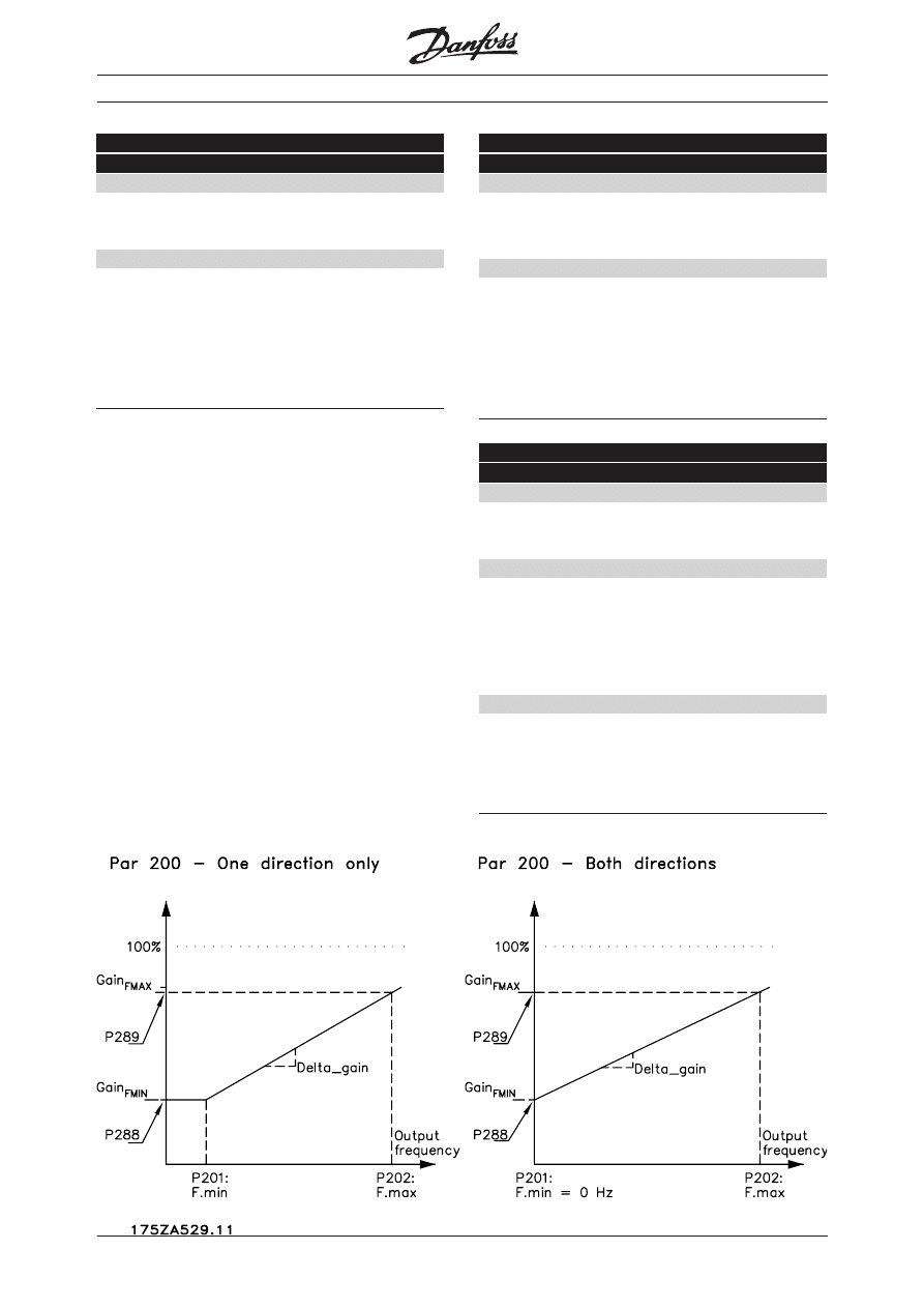
288
PID gain scale at min. ref.
Value:
0-100.00
Default is 100%
Function:
This parameter relates to P289 and is used to
calculate a gain scale factor that is multiplied with
the winder PID controller output (after clamping
P286/P287) to produce the final PID control output
(see the main block diagram).
Description of choice:
This function is mainly intended to stabilise the
process output at certain line speeds (references) by
reducting the proportional factor of the winder PID
controller at these speeds.
287 PID output positive clamp
Value:
0-100% (OFF)
Default is OFF
Function:
When active, this function performs a positive clamp
on the winder PID controller output value. The limit
value of the clamp is rated in percent of the max
frequency in P205. If OFF is selected the clamp has
no function and the winder PID controller output is
passed through the clamp.
Function of proportional gain scaling

VLT
®
5000 Series Winder Option
MG.50.K2.02 - VLT is a registered Danfoss trademark
8
290
Dancer zero setpoint
(DANCER ZERO)
Value:
-100.00 - 100.00 %
✭ 000.00 %
Function:
With this parameter the dancer zero setpoint, i.e the
tension reference for the PID controller, is selected.
Refer to figure on page 1.
Description of choice:
The percentage selected in this parameter is related
to the feedback range determined with parameter
414 and 415. If, for instance, 50 % is selected
steady-state operation is achieved when the
reference is at 50 % as well.
291
PID controller I-part reset
(RESET I-PART)
Value:
✭ Off (OFF)
[0]
On (ON)
[1]
Function:
With this parameter the integrator of the winder
specific PID controller is reset.
Description of choice:
When a reset is activated (On selected), the I-part is
reinitialized and the value in P291 is reset to zero.
Immediately after that the controller starts
integrating again. Refer to parameter 301 for the
description of this feature using terminal 17.
293
PID controller error inversion
(ERROR INVERSION)
Value:
✭ Off (OFF)
[0]
On (ON)
[1]
Function:
If the process is reversed, the sign of the error can be
inverted to take account for this situation.
Description of choice:
If this parameter is Off a feedback lower than the
dancer zero setpoint, will result in an increased output
of the controller and vice versa. If On is selected a
lower feedback results in a decreasing output and
vice versa. Please refer to parameter 303 for a
description of this feature using terminal 19.
294
Process Start Frequency function
(PR. START FREQ)
Value:
✭ Disable (DISABLE)
[0]
Enable (ENABLE)
[1]
Function:
The function of this parameter is to disable
respectively enable Process PID start frequency in
parameter 439.
Description of choice:
If Enable is selected, the VLT frequency converter
ramps the motor in open-loop from zero to the PID
start value defined by parameter 439.
Load & Motor
289
PID gain scale at max. ref.
Value:
0-100.00
Default is 100%
Function:
This parameter relates to P288 and is used to
calculate a gain scale factor that is multiplied with
the winder PID controller output (after clamping
P286/P287) to produce the final PID control output
(see the main block diagram).
Description of choice:
This function is mainly intended to stabilise the
process output at certain line speeds (references) by
reducting the proportional factor of the winder PID
controller at these speeds.
292
Line speed ref. inversion
(REF INVERSION)
Value:
✭ Off (OFF)
[0]
On (ON)
[1]
Function:
Whether the reference is added or subtracted to the
output of the PID controller is determined by this
parameter.
Description of choice:
If a bipolar input (± 10 V) is not available, it is
possible to indicate a changed polarity/changed
direction with this parameter. OFF means that the
frequency is added to the controller output and ON
results in a subtraction.

VLT
®
5000 Series Winder Option
9
MG.50.K2.02 - VLT is a registered Danfoss trademark
Digital inputs
Terminal no.
17
19
parameter
301
303
Inputs & Outputs
✭ = factory setting. ( ) = display text [ ] = value for use in communication via serial communication port
Value:
No function
(NO OPERATION)
[0]
[0]
Reset
(RESET)
[1]
Stop inverse
(STOP INVERSE)
[2]
Reversing
(REVERSING)
[1]★
Start reversing
(START REVERSE)
[2]
Only start anti-clockwise, on (ENABLE START REV)
[3]
[3]
Jog
(JOGGING)
[4]
Preset reference, on
(PRESET REF. ON)
[5]
Preset reference, msb
(PRESET REF. MSB)
[6]
Freeze reference
(FREEZE REFERENCE)
[7]★
Freeze output
(FREEZE OUTPUT)
[8]
Speed down
(SPEED DOWN)
[9]
Choice of Setup, msb
(SETUP SELECT MSB)
[10]
Slow-down
(SLOW DOWN)
[11]
Ramp 2
(RAMP 2)
[12]
Reset I-part
(RESET-I-PART)
[13]
Pulse reference
(PULSE REFERENCE)
[23]
301
Terminal 17, input
(DIGITAL INPUT 17)
Function:
With this parameter it is possible to assign different
functions to the digital input. Please refer to the
Operating Instruction. A new choice enabling a reset
of the process controller’s I-part is integrated for the
special winder software.
Description of choice:
Please refer to the Operating Instruction for a
description of choice (1)-(23). If Reset I-part [13] is
selected, a logical high signal on the terminal will reset
the I-part of the process controller. When the signal is
removed the I-part is reinitialized and the controller
starts integrating. A continuos signal on terminal 17
corresponds to disabling the I-part. See also the
description of parameter 291.
304
Terminal 19, input
(DIGITAL INPUT 19)
Function:
Refer to the Operating Instruction.
Description of choice:
If Reversing [1] is selected, activating the input will
result in an inversion of the PID error, c.f. parameter
293. If Inversion is selected in parameter 293 as well
as on terminal 19 the inversion settings will be
cancelled in both cases.
.
VLT
®
5000 Series Winder Option
MG.50.K2.02 - VLT is a registered Danfoss trademark
10
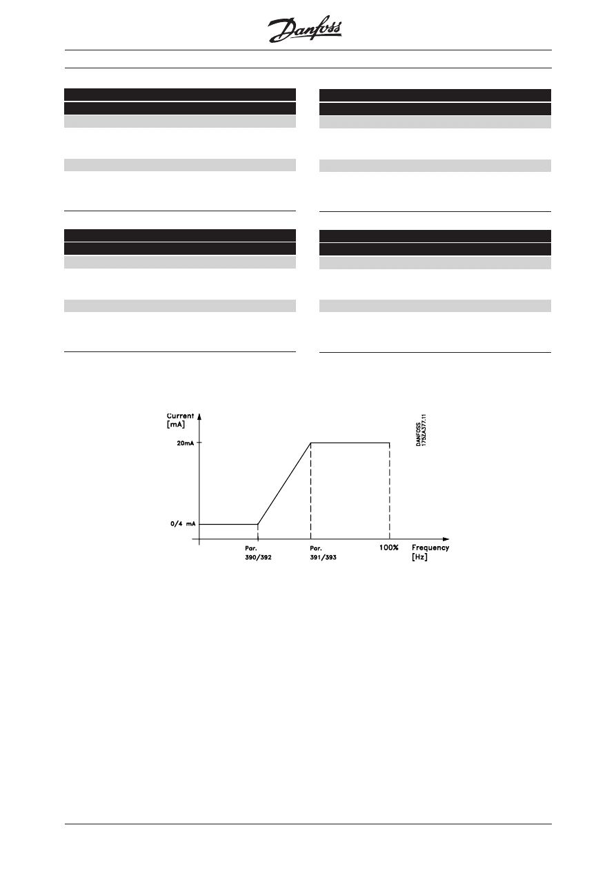
390
Terminal 42, output minimum scaling
(OUT 42 SCAL MIN)
Value:
000 - 100 %
✭ 000 %
Function:
The function of this parameter is to scale the analog
output signal on terminal 42, see figure below.
391
Terminal 42, output maximum scaling
(OUT 42 SCAL MAX)
Value:
000 - 100 %
✭ 100 %
Function:
The function of this parameter is to scale the analog
output signal on terminal 42, see figure below.
392
Terminal 45, output minimum scaling
(OUT 45 SCAL MIN)
Value:
000 - 100 %
✭ 000 %
Function:
The function of this parameter is to scale the analog
output signal on terminal 45, see figure below.
393
Terminal 45, output maximum scaling
(OUT 45 SCAL MAX)
Value:
000 - 100 %
✭ 100 %
Function:
The function of this parameter is to scale the analog
output signal on terminal 45, see figure below.
Inputs & Outputs

VLT
®
5000 Series Winder Option
11
MG.50.K2.02 - VLT is a registered Danfoss trademark
Parameter Setup List
Parameter:
Parameter:
Parameter:
Parameter:
Parameter: Value:
Value:
Value:
Value:
Value:
Setting:
Setting:
Setting:
Setting:
Setting:
Data
Data
Data
Data
Data
009
Display line2
010
Display line1.1
011
Display line 1.2
012
Display line 1.3
100
Configuration
Process control, closed loop
[4]
200
Output frequency range/direction
201
Output frequency low limit
202
Output frequency high limit
203
Reference/feedback range
204
Minimum reference
Only if [0] in P203
205
Maximum reference
This value relates to P415
286
PID output clamp in reverse operation
287
PID output clamp in forward operation
288
PID gain scale at min. ref.
289
PID gain scale at max. ref.
290
Dancer zero
292
Frequency offset inversion
293
PID controller inversion
294
Process start frequency function
301
Terminal 17, digital input
304
Terminal 19, digital input
308
Terminal 53, analogue input
Example: Dancer position as 0-10V feedback [2]
309
Terminal 53, min. scaling
-
0
310
Terminal 53, max. scaling
-
10
311
Terminal 54, analogue input
Example: Line speed of 0-10 V reference
[1]
312
Terminal 54, min. scaling
-
0
313
Terminal 54, max. scaling
-
10
414
Minimum feedback
415
Maximum feedback
This value relates to P205
416
Process units
Not important
437
Process PID normal /inverse
438
Process PID anti wind-up
439
Process PID start frequency
440
Process PID proportional gain
441
Process PID intergration time
442
Process PID differentiation time
443
Process PID diff gain limit
444
Process PID lowpass filter
■

MG.50.K2.02 - VLT is a registered Danfoss trademark
Danfoss can accept no responsibility for possible errors in catalogues, brochures and other printed material.
Danfoss reserves the right to alter its products without notice. This also applies to products already on order provided that such
alterations can be made without subsequential changes being necessary in specifications already agreed.
© Danfoss A/S (TG-MT2) 10.00
175R0166
175R0166
175R0166
175R0166
175R0166
Wyszukiwarka
Podobne podstrony:
Awangarda doc id 74335 Nieznany (2)
kolo 1 doc id 237073 Nieznany
E13 doc id 149200 Nieznany
LAB1 Sw i zast geom doc id 1052 Nieznany
E15 doc id 149221 Nieznany
Cinemania 1997 doc id 117144 Nieznany
LAB3 Sw i zast OFT doc id 10525 Nieznany
doc 4 id 138461 Nieznany
New Doc 1 id 317762 Nieznany
klasa 2 LO Matematyka doc id 23 Nieznany
EKSPRESJONIZM doc id 157089 Nieznany
ci gimin1 doc id 116543 Nieznany
Filmy obowiazkowe doc id 170161 Nieznany
LAB2 Sw i zast dB doc id 105257 Nieznany
Awangarda doc id 74335 Nieznany (2)
Abolicja podatkowa id 50334 Nieznany (2)
4 LIDER MENEDZER id 37733 Nieznany (2)
katechezy MB id 233498 Nieznany
metro sciaga id 296943 Nieznany
więcej podobnych podstron