1
INTRODUCTION
GENERAL
This section describes the operation of the Microproces-
sor Spark Timing System (MSTS). The MSTS ignition
system is used on engines that use an LPG fuel system.
REPAIRS and TROUBLESHOOTING procedures are
also in this section
DESCRIPTION
The general operation of the MSTS system is described
in the following paragraphs. The description of the com-
ponents and a circuit analysis is given in the paragraphs
under OPERATION.
What MSTS Does
The MSTS module receives signals from sensors
mounted on the engine and electronically processes the
information to adjust the ignition timing for the best fuel
use and engine performance.
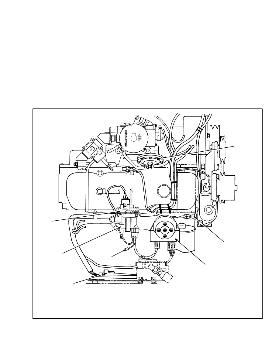
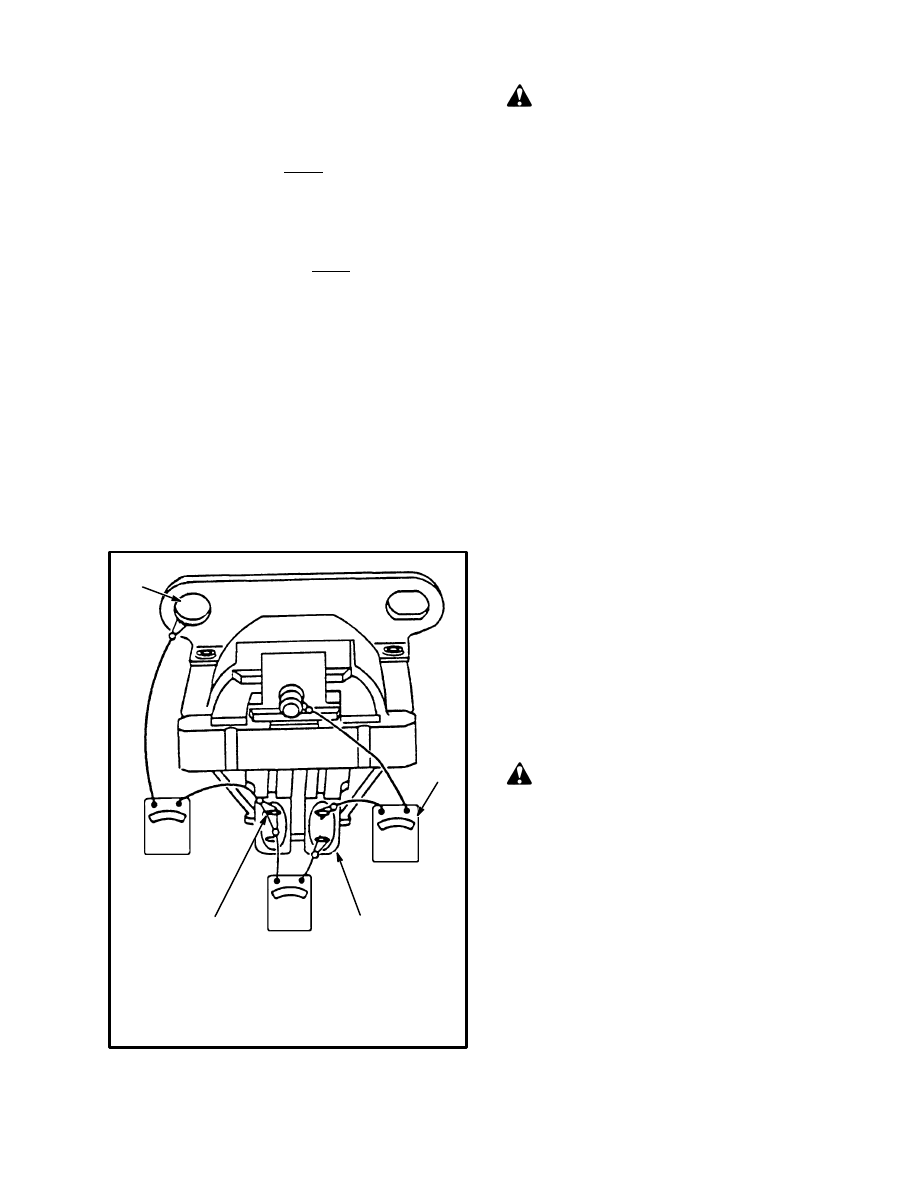
FIGURE 1. MSTS ARRANGEMENT IN THE ENGINE COMPARTMENT
1. GOVERNOR
2. ENGINE COOLANT TEMPERATURE
(ECT) SENSOR
3. DISTRIBUTOR
4. MSTS MODULE
5. TACHOMETER CONNECTOR
6. IGNITION COIL
7. MAP SENSOR
12909
1
2
3
4
5
6
7

2
The MSTS module receives signals from the following
sensors:
•
Manifold Absolute Pressure (MAP) sensor. This
sensor is a pressure transducer that measures the
atmospheric pressure before the engine is started.
The MSTS module uses this pressure as a refer-
ence. This sensor then measures changes in pres-
sure in the intake manifold during engine opera-
tion.
•
Engine Coolant Temperature sensor (ECT). This
sensor is a thermistor (resistor that is calibrated to
change its value as its temperature changes).
•
The ignition module is a small electronic module
within the distributor. This module is a signal
converter that senses the operation of the distrib-
utor. A sensing coil in the distributor senses the
rotation of the timer core and the ignition module
senses the speed of rotation. A square wave gen-
erator in the ignition module converts the pulses
from the sensing coil to a square wave signal that
is sent to the MSTS module. If the signals from
the ignition module to the MSTS indicate that the
engine is rotating at less than 400 rpm, the MSTS
module determines that the engine is being ro-
tated by the starter. The ignition module controls
the ignition for an engine being started. The Elec-
tronic Spark Timing (EST) function from the
MSTS module is deenergized. If the signals from
the ignition module to the MSTS module indicate
that the engine is rotating at greater than 400 rpm,
the MSTS module determines that the engine is
running and the Electronic Spark Timing (EST)
controls the ignition.
How MSTS Begins Operation
When the ignition switch is turned to ON, the MSTS
module measures the atmospheric pressure (BARO sig-
nal) from the MAP sensor. The MSTS module also
checks the signal from the engine coolant temperature
sensor (ECT). When the starter is engaged, the ignition
module sends electronic pulses to the MSTS module.
The frequency of the pulses indicates to the MSTS mod-
ule that the engine is being started. The ignition module
also electronically energizes (ON) and deenergizes
(OFF) the primary circuit of the ignition coil to create a
spark at the spark plugs.
When the engine starts, the frequency of the pulses from
the ignition module increases and indicates to the MSTS
module that the engine is running. The MSTS module
then sends a by–pass signal to the ignition module that
removes control of the spark (ignition) timing from the
ignition module. The MSTS module takes control of the
ignition timing and follows its program to give ignition
timing for the best engine operation. When the engine is
operating, the MSTS module continuously checks the
signals from the MAP, ECT, and distributor speed to
make timing adjustments for the engine operating con-
ditions.
OPERATION
Distributor
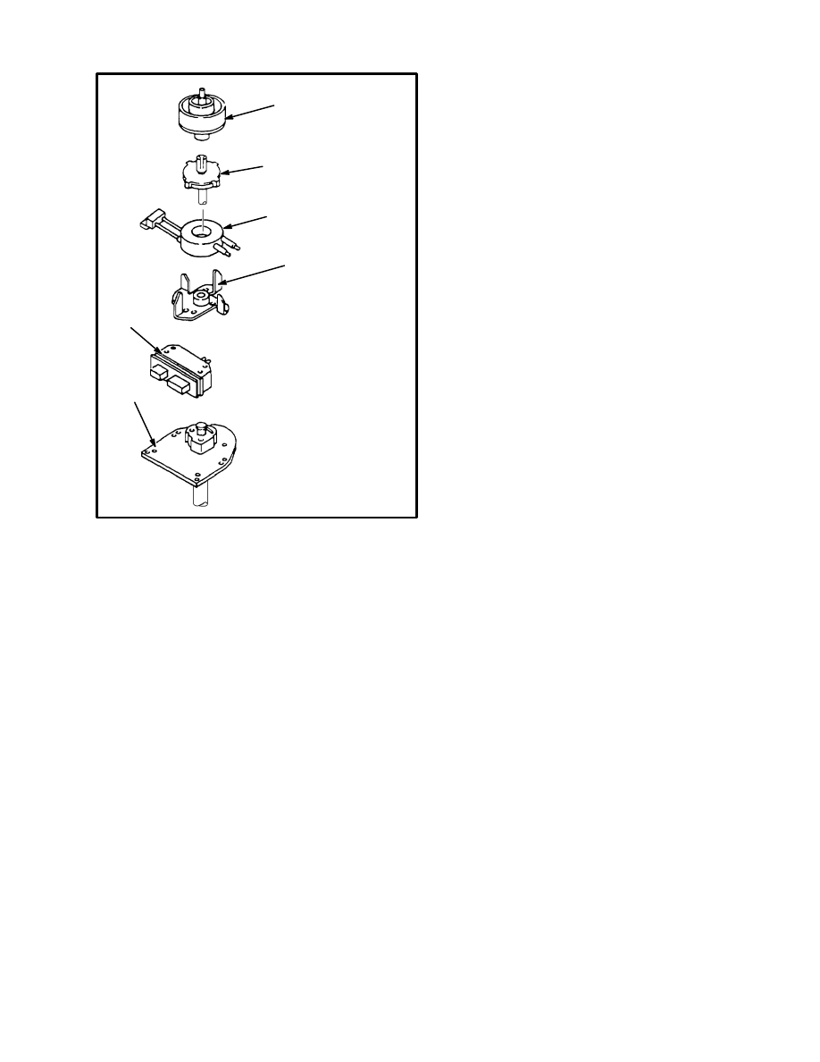
A timer core (permanent magnet) on the shaft of the dis-
tributor has external teeth which align with an equal
number of teeth on the pole piece. See FIGURE 2.
When the teeth of the timer core rotate past the teeth of
the pole piece, there is a decrease in the air gap between
the timer core and the pole piece. The magnetic field in-
creases. When teeth are not aligned, the magnetic field
decreases between the timer core and the pole piece. As
the timer core rotates, the magnetic field increases and
decreases in a cycle.
When a coil is near a changing magnetic field, a voltage
is generated in the coil. This principle is called magnetic
induction. A sensing coil is installed over the permanent
magnet. As the magnetic field near the pole piece
changes, a small voltage is generated in the sensing coil.
The principle of magnetic induction also controls the
polarity of the voltage generated in the coil. An increas-
ing magnetic field will generate a voltage in the coil that
is the opposite polarity of a magnetic field that is de-
creasing. This signal pulse causes the integrated circuits
in the ignition module to generate a square wave signal.
The ignition module and a magnetic pulse generator
control the primary circuit to the ignition coil when the
engine is started. After the engine is started, the MSTS
module receives the square wave signal from the mag-
netic pulse generator and ignition module as one of the
signals to control the EST. The pole piece has the same
number of teeth as the engine has cylinders so that a
spark voltage is correctly sent to each spark plug as the
shaft in the distributor rotates.
3
FIGURE 2. DISTRIBUTOR
1. ROTOR
2. TIMER
CORE/SHAFT
3. SENSING COIL
4. POLE PIECE
5. HOUSING
6. IGNITION
MODULE
1
2
3
4
5
6
Ignition Module
The ignition module is a solid–state electronic device
that operates like a fast switch except that it does not
have any moving or mechanical parts. See FIGURE 3.
Small electrical pulses from the sensing coil of the pulse
generator go to the ignition module.
The MSTS module must always know the speed at
which the engine is operating. The engine speed signal
is generated by the ignition module. The signal conver-
ter in the ignition module changes the signal voltage
from the sensing coil to a square wave reference signal
to the MSTS module. This square wave reference signal
for engine speed is called “REF HI”. The MSTS module
must also have a reference to compare with “REF HI”.
An additional wire between the MSTS module and the
ignition module is called “REF LO”. The “REF HI” and
“REF LO” connections give the PROM in the MSTS
module the necessary information about engine speed.
The other two wires between the MSTS module and the
distributor control the Electronic Spark Timing and are
called “EST” and “BY–PASS”.
NOTE: The ignition module controls spark timing only
when the the engine is being started. The MSTS module
controls the spark timing during engine operation. The
ignition module will also control the spark timing if
there are some failures in the signals to the MSTS mod-
ule. This “back–up” mode of operation will often permit
operation of the engine so that the lift truck can be
moved to an area for repair. The results of the failures in
signals to the MSTS module is described in the para-
graphs under MSTS Module Corrections.
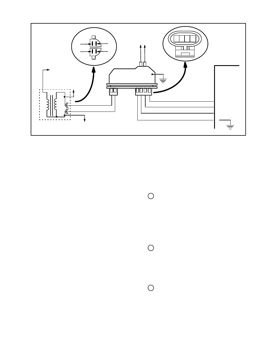
When the Engine Is Being Started
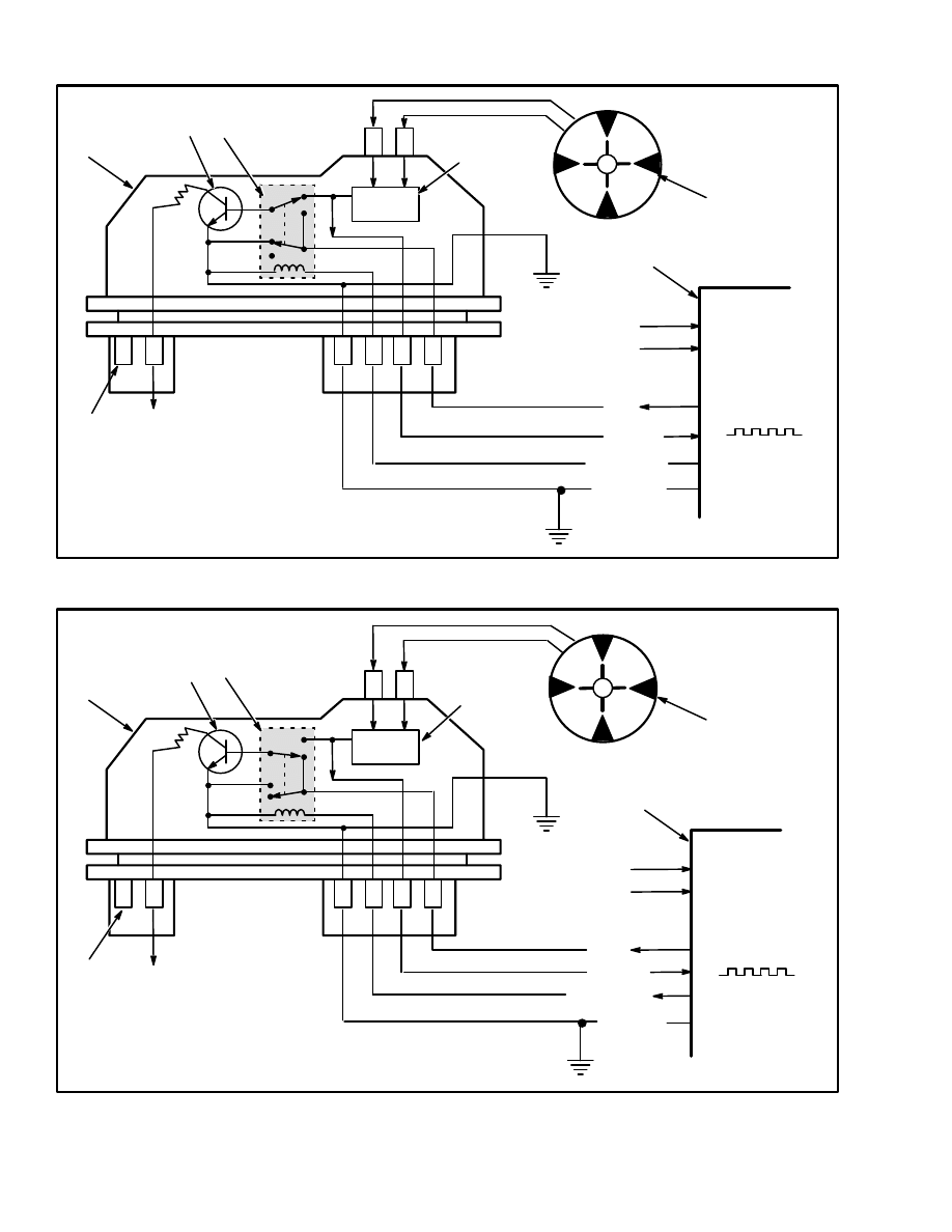
See FIGURE 3. When the engine is rotated by the start-
er, the electronic relay (2) is in the deenergized position.
The sensing coil is connected through the square wave
generator (3) to the base of the transistor (8).
When the sensing coil (4) applies a positive voltage (the
square wave voltage is increasing) to the transistor (8),
the transistor goes ON. When the voltage from the sens-
ing coil changes to negative (the square wave voltage is
decreasing), the transistor goes OFF. When the transis-
tor is ON, current flows through the primary winding of
the ignition coil. When the transistor goes OFF, the cur-
rent flow through the primary winding stops. The
changing magnetic field in the primary winding gener-
ates a high voltage in the secondary winding of the igni-
tion coil This high voltage generates a spark at the spark
plug.
When the Engine Is Running
See FIGURE 4. When the engine speed is approximate-
ly 400 rpm, the MSTS module determines that the en-
gine is running and applies 5 volts on the “BY–PASS”
wire to the ignition module. This voltage energizes the
electronic relay (2) and makes the following changes:
The “EST” wire is not grounded and is now connected to
the base of the transistor (8). The sensing coil is discon-
nected from the base of the transistor (8).
The ignition module and the ignition timing is now con-
trolled by the “EST” signal from the MSTS module.
This mode of operation is called the “EST mode”.
4
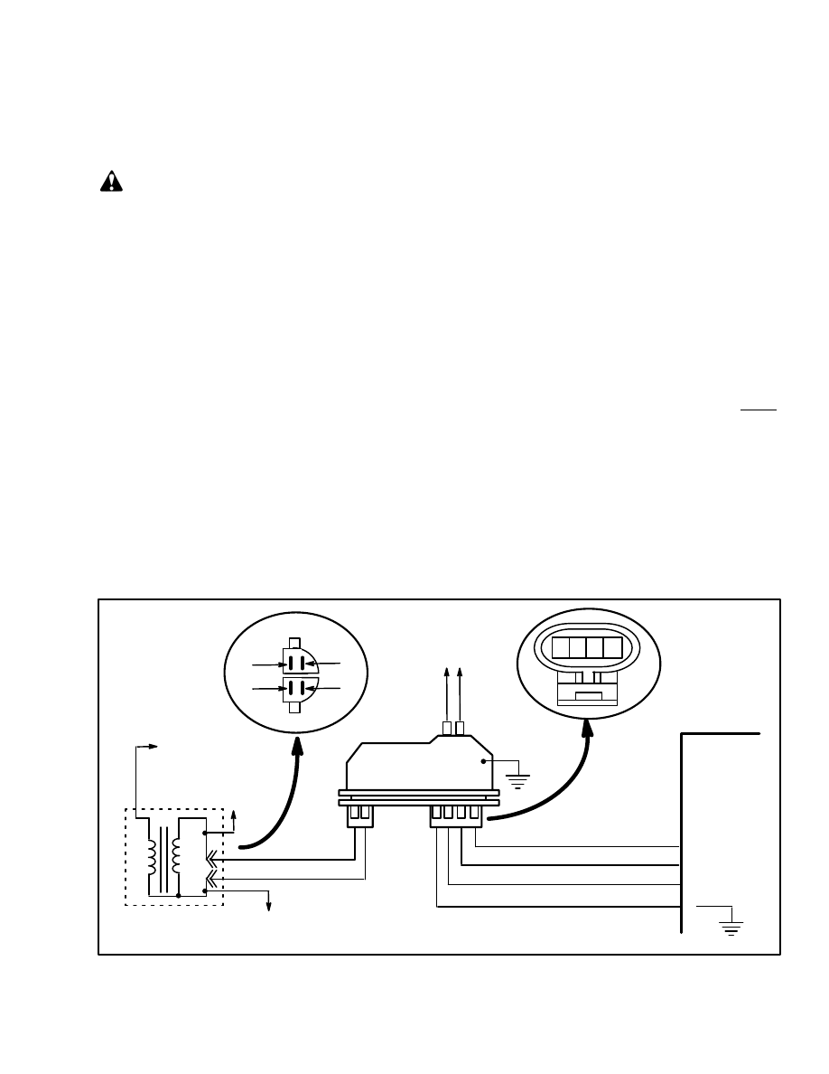
FIGURE 3. IGNITION MODULE WHEN ENGINE IS BEING STARTED
EST
REF HI
BY–PASS
5
G
B
R
E
+
C
P
N
ÉÉÉÉ
ÉÉÉÉ
ÉÉÉÉ
7
1
3
8
2
6
4
A
B
C
D
1. IGNITION MODULE
2. ELECTRONIC RELAY
3. SQUARE WAVE GENERATOR
4. SENSING COIL
5. MSTS MODULE
6. BATTERY VOLTAGE
7. TO IGNITION COIL
8. TRANSISTOR
F
D
E
K
GROUND
NO VOLTAGE
APPLIED
MAP SENSOR
ECT SENSOR
REF–LO
FIGURE 4. IGNITION MODULE WHEN ENGINE IS RUNNING
EST
REF HI
BY–PASS
MAP SENSOR
CTS SENSOR
5
G
B
R
E
+
C
P
N
ÉÉÉÉ
ÉÉÉÉ
7
1
3
8
2
6
4
A
B
C
D
1. IGNITION MODULE
2. ELECTRONIC RELAY
3. SQUARE WAVE GENERATOR
4. SENSING COIL
5. MSTS MODULE
6. BATTERY VOLTAGE
7. TO IGNITION COIL
8. TRANSISTOR
F
D
E
K
NOT GROUND
5V APPLIED
REF–LO
5
Manifold Absolute Pressure (MAP) Sensor
The Manifold Absolute Pressure (MAP) sensor is a
pressure transducer that measures changes in the pres-
sure in the intake manifold. See FIGURE 5. The pres-
sure changes are a result of engine load and speed
changes. The MAP sensor converts these pressure
changes to a signal voltage to the MSTS module.
The MSTS module sends a 5 volt reference signal to the
MAP sensor. When the pressure in the intake manifold
changes, the electrical resistance in the MAP sensor also
changes. The change in the voltage signal from the MAP
sensor enables the MSTS module to sense the pressure
in the intake manifold.
A closed throttle causes a low pressure (high engine vac-
uum) in the intake manifold. This low pressure causes a
low voltage signal from the MAP sensor to the MSTS
module. A fully opened throttle causes a higher pressure
(low engine vacuum) in the intake manifold. This higher
pressure causes a higher voltage signal from the MAP
sensor to the MSTS module. These pressure changes in-
dicates the load on the engine to the MSTS module. The
MSTS module then calculates the spark timing for the
best engine performance.
The MAP sensor also measures the barometric pressure
when the key switch is turned to ON and before the en-
gine is started. The MSTS module “remembers” the
barometric pressure (BARO signal) after the engine is
running. The MSTS module then automatically adjusts
the ignition timing for different altitudes and atmo-
spheric conditions.
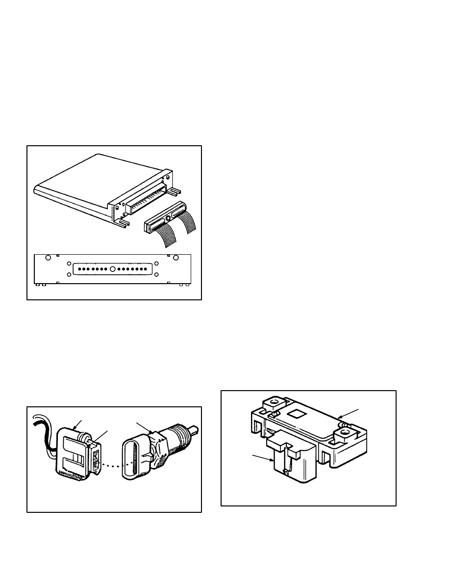
FIGURE 5. MAP SENSOR
1. SENSOR
2. ELECTRICAL
CONNECTOR
2
1
Engine Coolant Temperature (ECT) Sensor
The engine coolant temperature (ECT) sensor
(FIGURE 6.) is a resistor that changes its resistance val-
ue when the temperature changes (thermistor). This sen-
sor is installed in the engine coolant system. A low cool-
ant temperature makes the thermistor have a high resis-
tance [100 700 ohms at –40
°
C (–40
°
F)]. A higher cool-
ant temperature makes the thermistor have a lower resis-
tance [77 ohms at 130
°
C (266
°
F)].
The engine coolant temperature sensor uses a thermistor
to control the signal voltage to the MSTS module. The
MSTS module applies a 5–volt reference voltage to the
ECT. See FIGURE 7. The reference voltage will be high
when the engine coolant is cold. The reference voltage
will be lower when the engine coolant is at operating
temperature. The MSTS module will adjust the ignition
timing for more spark advance when the engine coolant
is cold and less spark advance when the engine coolant
is hot. An engine at operating temperature normally
needs less spark advance.
FIGURE 6. ENGINE COOLANT TEMPERATURE
(ECT) SENSOR
1. TEMPERATURE SENSOR
2. ELECTRICAL CONNECTOR
3. LOCK TAB
2
1
3
MSTS Module Corrections
The operation of the MSTS module was described in
earlier paragraphs. (See the description in “What MSTS
Does”) These paragraphs describe the corrections made
by the MSTS module.
The MSTS module does a check of the system compo-
nents. A set of normal operating limits are part of the
PROM program. If a sensor sends a signal that is outside
of the limits of the PROM program, the MSTS module
will not use the information. The MSTS module will use
a standard value from its program and continue to oper-
ate the MSTS.
The following examples are the action of the MSTS
module if it finds a problem:
MAP Sensor Signal Voltage Is Too High Or
Too Low. The MSTS module will use a MAP val-
6
ue from its PROM program and use this value to
calculate the ignition timing
ECT Signal Voltage Is Too High Or Too Low.
When a coolant sensor error occurs, the MSTS
module will use a value that is approximately the
normal operating temperature of the coolant.
Open Circuit From The MSTS Modules To
The Ignition Module. If the EST circuit is open,
it can not be at ground potential and the EST sig-
nal will rise and fall from the sensing coil. The en-
gine will not run. If the EST circuit becomes open
when the engine is running, it will stop.
Short–Circuit (Grounded Circuit) From The
MSTS Module To The Ignition Module. When
the engine is being rotated by the starter, the
MSTS module normally detects 0 volts in the
EST circuit because the circuit is at ground poten-
tial in the ignition module.
The MSTS module would not detect a problem
until the engine began to run. The MSTS module
could not operate in the EST mode and the engine
will not operate. If the EST circuit has a short–cir-
cuit (grounded circuit) when the engine is run-
ning, it will stop.
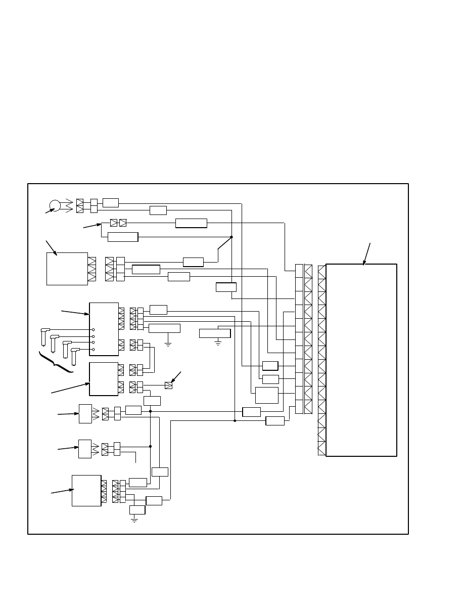
FIGURE 7. MSTS WIRING DIAGRAM
P
N (Not Used)
M
L
K
J
H
G
F
E
D
C (Not Used)
B (Not Used)
A (Not Used)
A
B
C
C
+
E
R
B
G
1. MSTS MODULE
2. GOVERNOR CONTROLLER
3. MSTS FUSE
4. GOVERNOR SOLENOID VALVE
5. IGNITION COIL
6. SPARK PLUGS
7. TACHOMETER CONNECTOR
8. DISTRIBUTOR AND IGNITION MODULE
9. MAP SENSOR
10. INITIAL TIMING CONNECTOR
11. ENGINE COOLANT TEMPERATURE SENSOR
12 VOLT +
1
2
3
4
+
+
A
C
G
H
BLK/RED
PINK
DK GRN
WHT
ORG
BRN
YEL
BLK
BLK/WHT
PURP
GRAY
PURP/
WHT
WHT
WHT
BLK
RED
BRN
YEL
B
A
B
A
1
2
3
4
5
6
7
8
9
10
11
BLK/WHT
D
C
B
A
PURP
YEL
BLK/RED
7
Open Circuit Or Short–Circuit In The BY–
PASS Circuit. The MSTS module would not de-
tect a problem until the engine began to run. The
MSTS module could not operate in the EST mode
and the engine would operate with reduced pow-
er. If this problem occurs when the engine is run-
ning, the engine will only operate in the starting
mode with the ignition module.
Open Circuit Or Short–Circuit In The REF
HI Circuit. The MSTS module would not detect
that the engine was operating. The MSTS module
could not operate in the EST mode and the engine
would operate with reduced power. If this prob-
lem occurs when the engine is running, the en-
gine will only operate in the starting mode with
the ignition module.
Open Circuit Or Short–Circuit In The REF
LO Circuit. The MSTS module would not have a
comparison for operation. The MSTS module
could not operate in the EST mode and the engine
will not operate. If this problem occurs when the
engine is running, it will stop.
Initial Timing Connector
In addition to the sensor inputs, the MSTS module
checks the voltage in a wire from a special plug called
the “initial timing connector”.
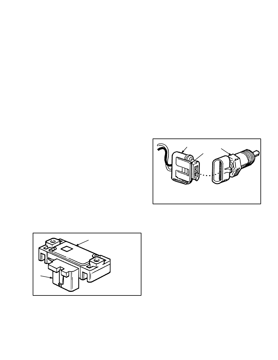
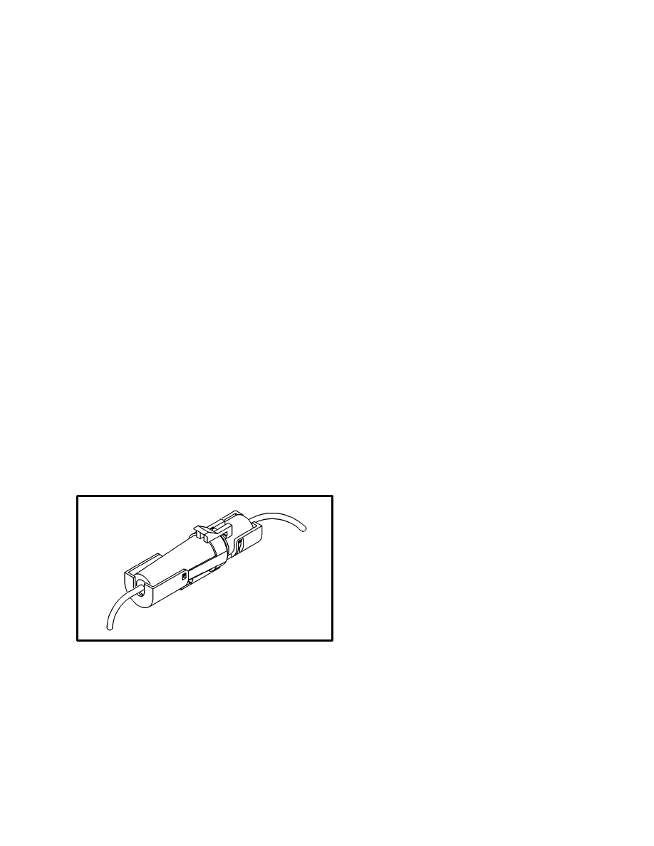
FIGURE 8. INITIAL TIMING CONNECTOR
This initial timing connector is installed in the engine
electrical harness to the distributor. This initial timing
connector is opened to adjust the initial ignition timing.
When the initial timing connector is opened, the correct
timing adjustment is 8
°
BTDC. The ignition timing after
the initial timing connector is installed is controlled by
the MSTS module.
GOVERNOR SYSTEM (See FIGURE 1.)
The governor system controls the maximum engine
speed under variable load conditions. The governor at-
taches to the carburetor throttle assembly. The governor
controller is on the cowl in the operator compartment.
Vacuum lines connect the governor solenoid valve to the
carburetor and to the diaphragm of the governor. The
governor controller is electrically connected to the gov-
ernor solenoid valve, MSTS module and the ignition
coil.
The operation of the governor is controlled by the gov-
ernor controller. Manifold vacuum and air pressure pro-
vide the force to actuate the governor. The governor
controller controls this force. The governor diaphragm
operates the throttle plate of the carburetor. Linkage
from the diaphragm closes the throttle plate when the
vacuum is high. A spring in the governor opens the
throttle plate.
The governor controller is connected to the MSTS mod-
ule and controls the operation of the governor solenoid
valve. The governor solenoid valve controls the vacuum
at the diaphragm in the governor. During operation, the
governor controller receives the engine speed signals.
As the engine speed reaches the limit of the governor,
current flows to the governor solenoid valve. The sole-
noid valve closes, causing vacuum to operate the dia-
phragm. When actuated, the diaphragm works against
the governor spring to close the throttle plate and de-
crease engine speed. The governor solenoid valve opens
and closes as necessary to keep the engine speed within
the governor limits.
8
A
B C D E
F G
H J
K L
M N P
14–PIN CONNECTOR
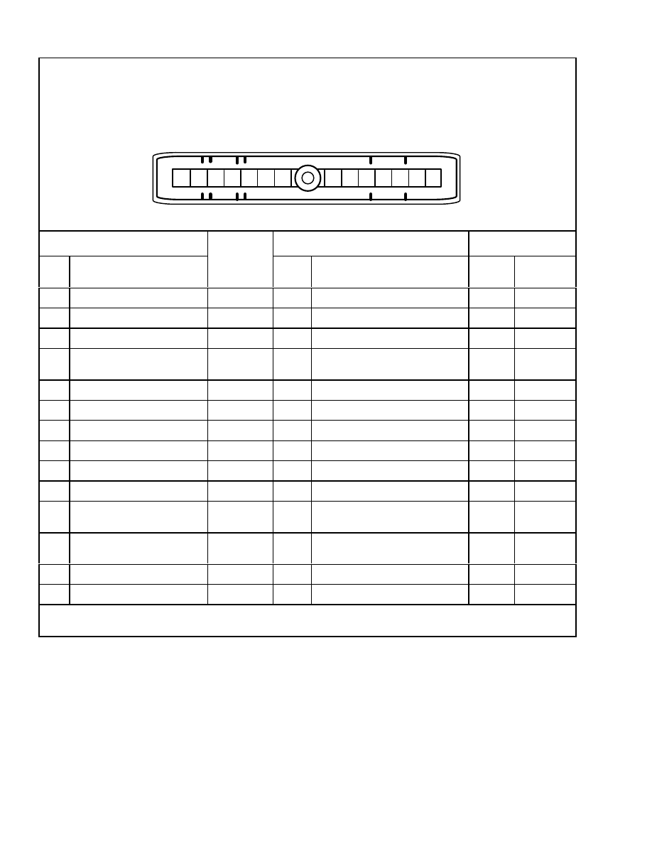
This voltage chart is for use with a digital voltmeter when doing troubleshooting. There can be small variations
in the voltage shown in the chart from those voltages measured during troubleshooting. These small variations
are because of the battery charge and other resistances in the connections. A variation of more than 0.5 volts
can be an indication of a malfunction.
When this chart is used for troubleshooting, the engine must be at its operating temperature and the engine
must be at idle speed (for ENGINE RUNNING column).
MSTS MODULE CONNECTOR
WIRE
COLOR
SENSOR CONNECTOR
NORMAL VOLTAGE
PIN
FUNCTION
COLOR
PIN
FUNCTION
KEY
ON
ENGINE
RUNNING
A
Not Used
–
–
–
–
B
Not Used
–
–
–
–
C
Not Used
–
–
–
–
D
Reference
Orange
White
C
H
Ignition Module
Governor Controller
0
1.3
E
By–pass
Purp/White
B
Ignition Module
0
4.75
F
EST
White
D
Ignition Module
0
1.3
G
ECT Sensor
Yellow
B
MSTS To ECT Sensor
1.6*
1.6*
H
MAP Sensor Signal
Dk Green
B
Manifold Absolute Pressure
4.75**
1.1**
J
+5 Volt Reference – MAP
Gray
C
Manifold Absolute Pressure
5.0
5.0
K
System Ground
Black/Red
0
0
L
Ignition
Pink
Battery Voltage From Ignition
Switch
B+
B+
M
Ground Connector For
Sensors
Purple
A
MAP Sensor, ECT Sensor, Ini-
tial Timing Connector
0
0
N
Not Used
–
–
–
–
P
Initial Timing Connector
BLK/WHT
–
5.0
5.0
*
Voltage changes with temperature.
**
Voltage changes with atmospheric pressure.
FIGURE 9. MSTS MODULE CONNECTIONS

9
TROUBLESHOOTING
GENERAL
The following troubleshooting charts are designed to
give an efficient method of fault analysis on the MSTS.
WARNING
This troubleshooting requires the operation of the
engine for some of the tests. Make sure the tests are
done carefully to prevent injury:
•
Put the lift truck on a level surface. Lower the
carriage and forks and apply the parking
brake. Make sure the lift truck can not move
and cause an injury during the tests. Put
blocks in front and back of the drive tires to
prevent movement of the lift truck.
•
The fuel system and the engine must operate
correctly. Any problems or leaks in the fuel
system or the engine must be repaired before
doing troubleshooting on the MSTS.
•
The fan and the drive belts can remove fingers
or cause other injuries. Be careful that your
hands and tools do not touch the moving fan or
the drive belts.
•
The engine exhaust and other parts of the en-
gine are hot. Do not touch a hot surface and
cause a burn.
CAUTION
Electronic equipment can be damaged if trouble–
shooting and repairs are not done correctly. The fol-
lowing CAUTIONS must be followed when doing
troubleshooting or repairs on an engine with MSTS:
•
Always disconnect the battery negative cable
before disconnecting and removing any parts
of ignition system.
•
Never disconnect the battery from any equip-
ment when the engine is running.
•
If the battery must be charged with a battery
charger, ALWAYS disconnect the battery
from the electrical system.
•
Make sure that all electrical connections are
clean and have good electrical contact.
•
Never connect or disconnect the wiring har-
ness at the MSTS module when the key switch
is “ON”.
•
Always disconnect the battery and the MSTS
module connectors if electric arc welding must
be done on the vehicle.
•
Make sure that any water or steam is not sent
toward the MSTS module or its sensors if the
engine compartment is cleaned with steam.
The heat and steam can damage the electronic
components and cause corrosion in the electri-
cal connections.
•
Use only the tools and test equipment de-
scribed in “TOOLS AND TEST EQUIP-
MENT” to prevent damage to good compo-
nents and to obtain correct test results.
•
All voltage measurements must be done with a
digital voltmeter with a rating of 10 megohm
input impedance.
•
When a test light is used in troubleshooting,
the test light must have less than 0.3 amps (300
milliamps) of maximum current flow. A test
for a correct test light is shown in FIGURE 10.
TOOLS AND TEST EQUIPMENT
The following tools are necessary for troubleshooting
the MSTS:
•
Ohmmeter
•
Digital voltmeter. The voltmeter must have a
minimum input impedance of 10–megohms. (A
digital voltmeter and ohmmeter are normally in-
cluded in a multi–meter test instrument.
•
Tachometer with inductive trigger signal sensor.
•
Test light that has a low current draw as described
in FIGURE 10.
•
Vacuum pump with a gauge. This vacuum pump
is held and operated with the hand. The gauge
must be able to indicate a gauge pressure (vacu-
um) of 34 kPa [20 inches of mercury (20” Hg)].
(See the PRESSURE CONVERSION CHART at
the end of this section.)
10
•
Spark tester. The spark tester is used to check the
secondary ignition. The spark tester is also called
an ST125 and creates a 25 kilovolt load on sec-
ondary ignition components.
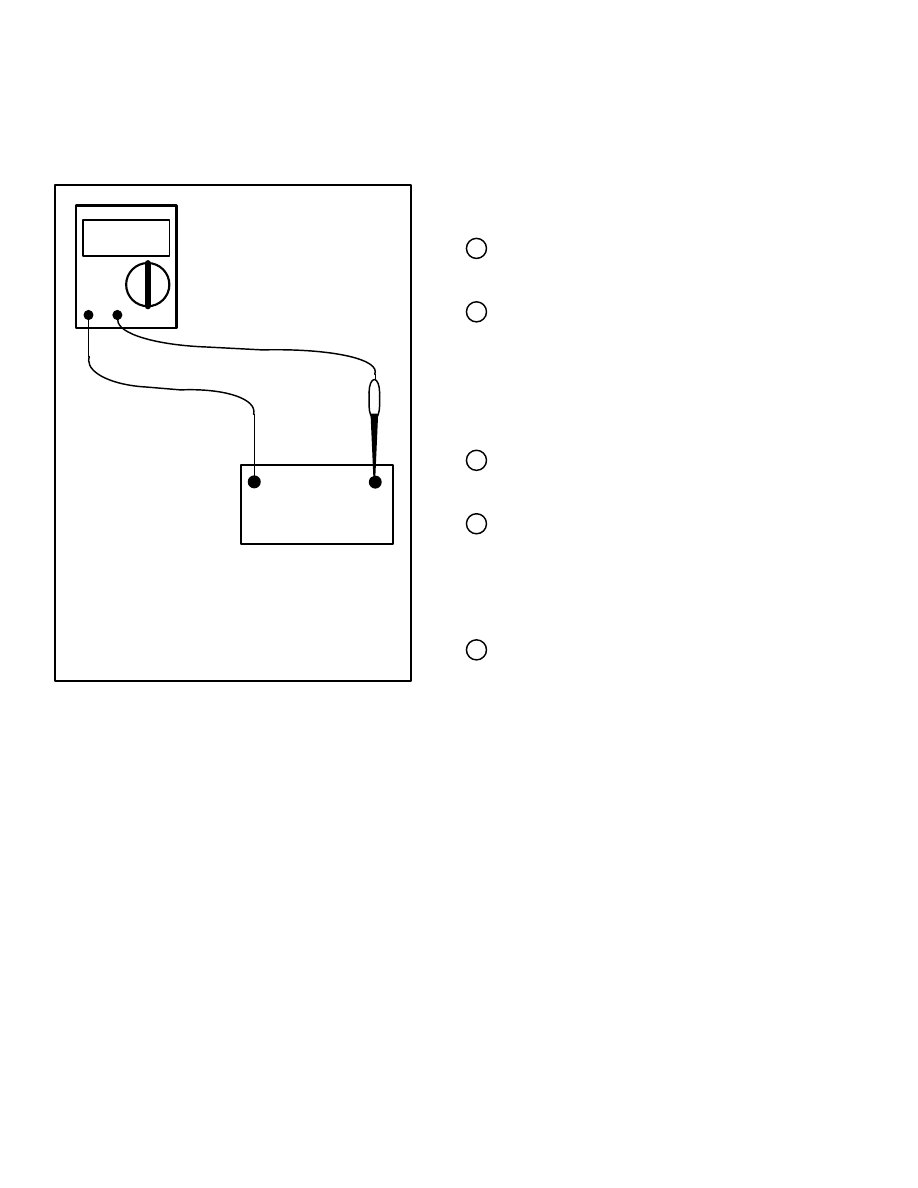
FIGURE 10. CURRENT FLOW TEST FOR A
TEST LIGHT
If the ammeter indicates less than 0.3 amps
(300 milliamps), the test light can be used.
If the ammeter indicates more than 0.3
amps (300 milliamps), the test light can not
be used because it can cause damage to
the electronic components.
DC Amps
+
–
BATTERY
TEST
LIGHT
MSTS
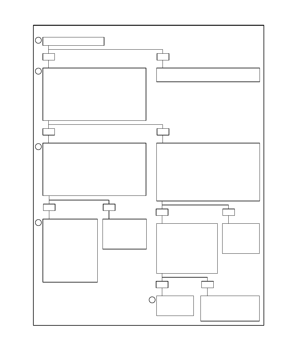
Test Description (See FIGURE 11.)
The numbers in circles on the troubleshooting chart
have the following indications:
1 This step checks if there is a problem in the basic
distributor or ignition coil assembly.
2 This step checks if the Electronic Spark Timing
(EST) is working. If the initial timing connector
is disconnected when the engine is running, the
EST reference signal is removed from the igni-
tion module. The engine runs only with a timing
of 8
°
BTDC.
3 This step checks the operation of the MAP sen-
sor.
4 The parts of the MSTS operate correctly when the
engine is at normal operating temperature, but
not when the engine is cold. There is a
troubleshooting chart for the engine coolant tem-
perature sensor (ECT).
5 In addition to checking the wires for an open cir-
cuit, make sure to check the fastening screw for
the ignition module. The MSTS is grounded
through this screw.
11
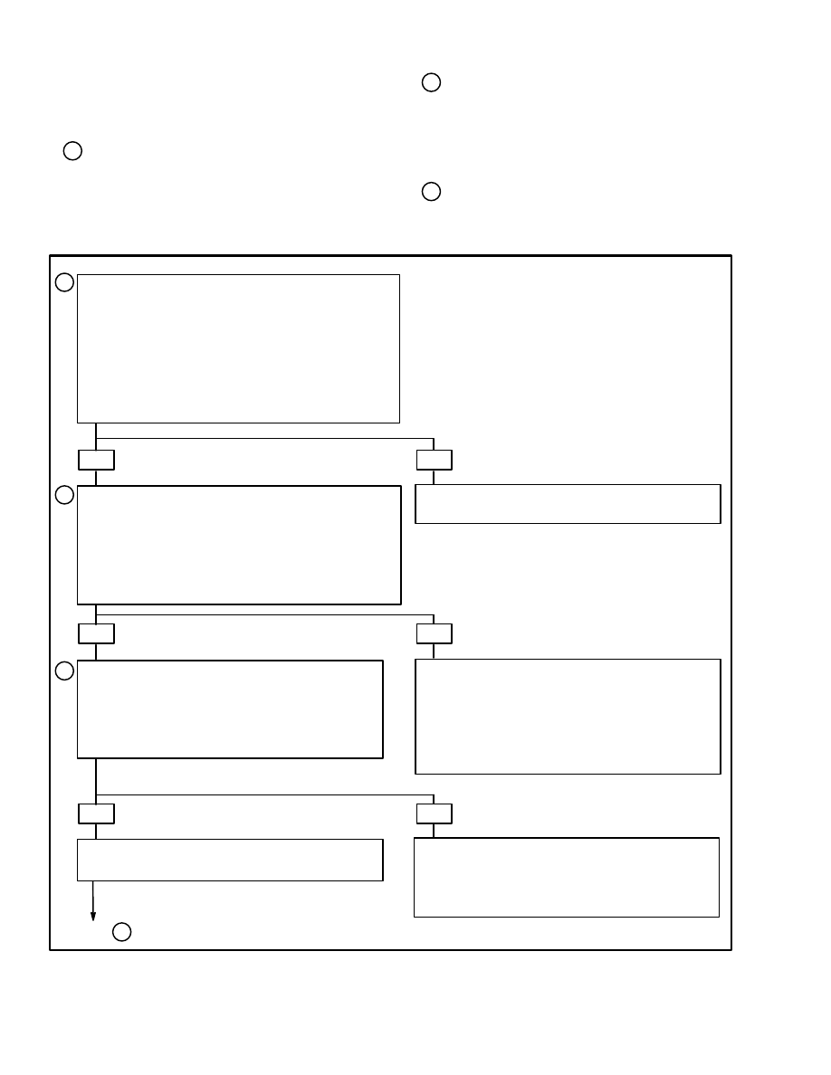
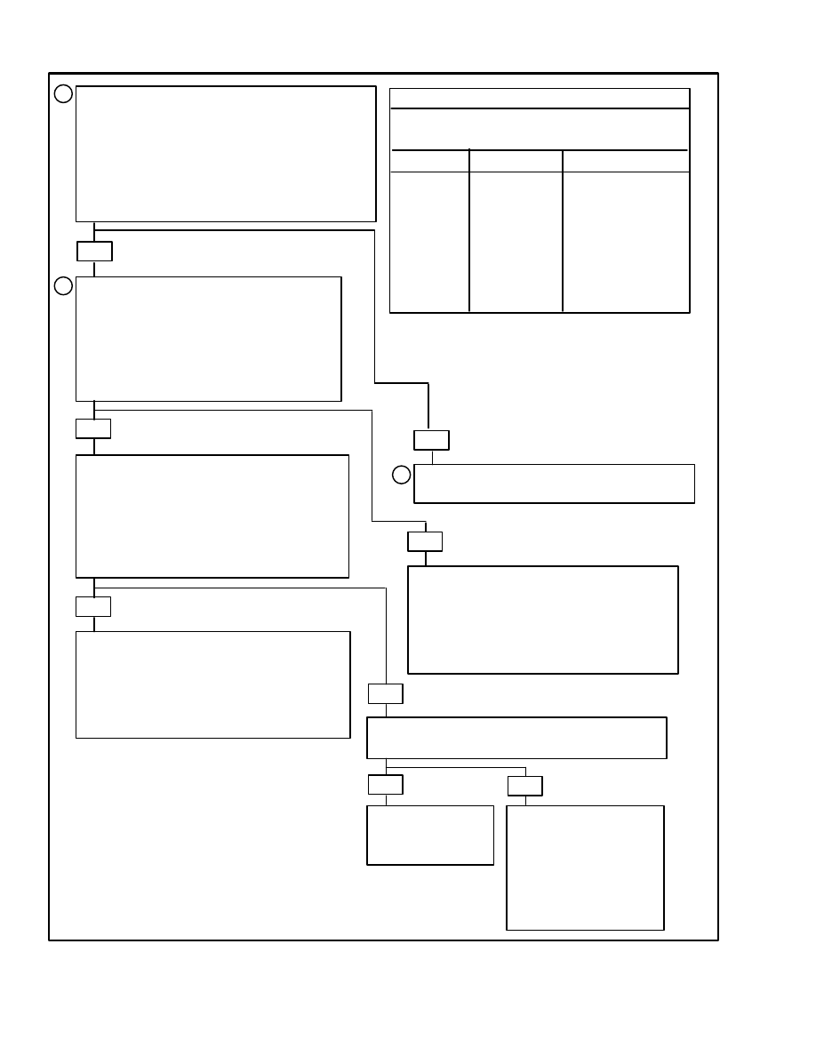
FIGURE 11. MSTS TROUBLESHOOTING CHART
NOTE: Make sure the fuel system is operating correctly before using this chart.
Does the engine start?
YES
NO
a. Run the engine at normal operating
temperature for two minutes.
b. Run the engine at a constant speed of 1500
rpm.
c. Remove the initial timing connector from its
socket.
d. Did the rpm decrease when the initial timing
connector was removed?
See FIGURE 13. “IGNITION SYSTEM
TROUBLESHOOTING CHART”
YES
NO
a. Install the initial timing connector into its
socket.
b. Run the engine at a constant speed of 1500
rpm.
c. Disconnect the electrical connection for the
MAP sensor.
d. Did the engine speed change when the MAP
sensor was disconnected?
a. Turn the key switch to OFF.
b. Disconnect the 14–pin connector from the
MSTS module.
c. Connect a test light to ground.
d. Turn the key switch to ON.
e. Touch the probe of the test light to terminal L
of the 14–pin connector.
f. Is the test light illuminated?
YES
NO
a. Connect a test light to
B+.
b. Touch the probe of the
test light to terminal K of
the 14–pin connector.
c. Is the test light
illuminated?
Repair an open
circuit or a
short–circuit in
the ignition
circuit.
YES
NO
See FIGURE 15.
“ELECTRONIC SPARK
TIMING (EST) TROUBLE–
SHOOTING CHART”.
Repair the
open circuit in
the REF LO.
YES
NO
a. Connect the MAP
sensor again.
b. Turn the key switch
to OFF.
c. MSTS is operating
correctly.
d. If problem still
exists, check for other
troubleshooting
faults.
See “MANIFOLD
ABSOLUTE
PRESSURE
(MAP) TROUBLE–
SHOOTING”.
1
2
3
4
5
12
A B C D
G B R E
+
C
P N
D
E
F
K
TACH
CONN.
TO
IGN
IGNITION
COIL
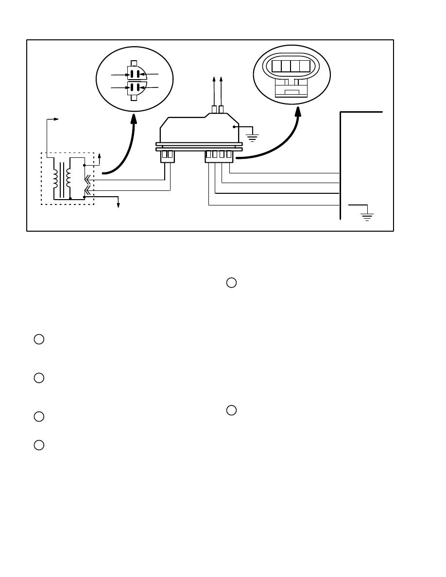
FIGURE 12. IGNITION SYSTEM CIRCUIT
TACH
CONN.
+
C
IGN
C
A B
D
EST
REFERENCE
BY–PASS
MSTS
MODULE
SENSING
COIL
IGNITION
MODULE
DISTRIBUTOR
4–TERMINAL
CONNECTOR
TO
DISTRIBUTOR
IGNITION COIL
CONNECTOR
IGNITION SYSTEM
Test Description (See FIGURE 12.)
If a tachometer has been connected to the TACH
CONN., disconnect it before doing this test. The num-
bers in circles on the troubleshooting chart
(FIGURE 13.) have the following indications:
1 Check a minimum of two spark plug wires to
make sure that one of the spark plug wire does not
have an open circuit.
2 If a spark occurs when the EST connector is dis-
connected, the output from the sensing coil is too
low for EST operation.
3 A spark indicates that the fault is in the distributor
cap or the rotor.
4 The normal voltage at the C and the + terminals is
battery voltage. A low voltage can indicate:
a. An open circuit or a high resistance circuit from
the distributor to the ignition coil or
b. An open circuit in the primary winding of the
ignition coil.
If the voltage at C is less than battery voltage, and
there is 10 volts or more at +, there is an open cir-
cuit from C to the ignition coil or an open circuit
in the primary winding of the ignition coil.
5 Check for a short–circuit in the ignition module
or in the circuit from the ignition coil to the igni-
tion module. Check for approximately 12 volts
between the TACH CONN. and ground.
If the voltage is low (approximately 1 to 6 volts),
there can be a fault in the ignition coil. This con-
dition can cause a failure in the ignition coil from
too much heat. If there is an open circuit in the
primary winding of the ignition coil, a low volt-
age can “leak” through the ignition module from
the B+ to the TACH CONN. terminal.
6 The ignition module normally goes ON when 1.5
to 8 volts is applied to terminal P. When the igni-
tion module is ON, the voltage between the
TACH CONN. and ground will normally de-
crease to 7 to 9 volts. This test checks if the sens-
ing coil or the ignition module has a fault. When
1.5 to 8 volts is momentarily applied to terminal
P, this voltage acts as a trigger voltage that re-
places the voltage from the sensing coil. The pro-
cedure in FIGURE 13. shows a test light, but any
low voltage, low current source can be used as a
trigger voltage.
13
7 When the momentary trigger voltage is removed,
a spark is normally generated through the igni-
tion coil. If no spark occurs, replace the ignition
coil. If a spark occurs, check the sensing coil and
the rotating timer core.
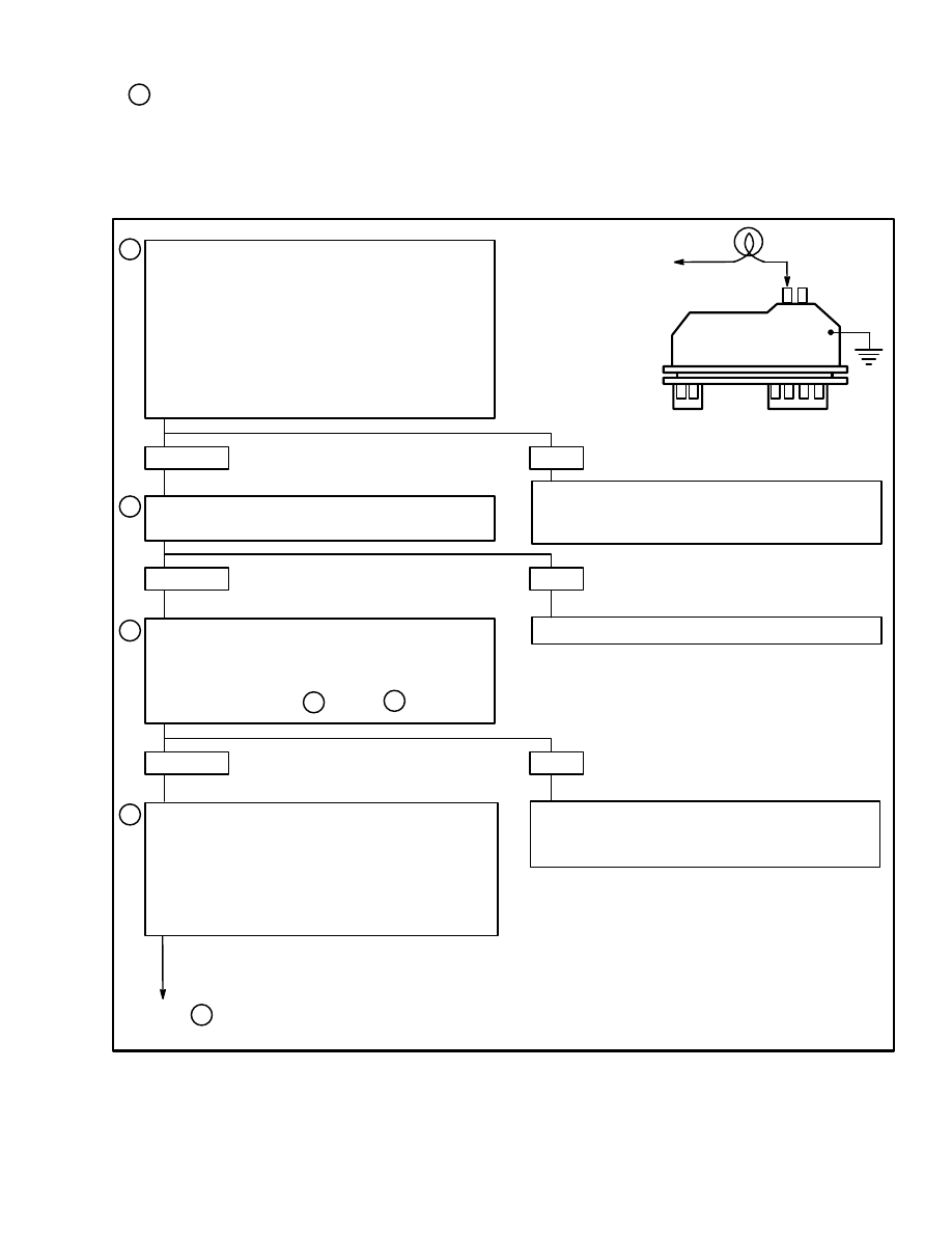
FIGURE 13. IGNITION SYSTEM TROUBLESHOOTING CHART (1 of 2)
NO SPARK
SPARK
Disconnect the 4–terminal distributor connector
and check for a spark.
Check for fuel supply to engine. Check spark
plugs. Check for other faults not in the ignition
system.
Check for spark at coil wire while rotating the
engine with the starter. (If the spark tester is
being used, leave the spark tester connected to
the coil wire for steps through .)
Inspect the distributor cap for water, cracks, or
other damage. If the distributor cap is correct,
replace the distributor rotor.
1
2
3
G B R E
+
C
P N
TEST LIGHT
TO DC
PWER SUPPLY
(1.5 TO 8 V)
a. If a tachometer has been connected to the
TACH CONN., disconnect it.
b. Turn the key switch to ON and use the
starter to rotate the engine. Check for a spark
at the spark plug. Use a spark tester (ST–125)
if it is available. If there is no spark on one wire,
check another wire. A few sparks and then
nothing is the same as no spark.
NO SPARK
SPARK
4
7
NO SPARK
SPARK
Replace sensing coil.
4
a. The engine is stopped. Turn the key switch
to ON.
b. Disconnect the 2–terminal C and +
connector at the distributor.
c. Check the voltage at the C and + terminals
of the wires from the ignition coil.
Go to on next page.
5
IGNITION
MODULE
14
a. Connect the 2–terminal C
and + connector at the
distributor.
b. Turn the key switch to ON.
Check the voltage between the
TACH CONN. and ground.
a. Disconnect the distributor 4–terminal connector.
b. Remove the distributor cap. Disconnect the sensing
coil from the ignition module.
c. Connect a voltmeter from the TACH CONN. to ground.
Turn key switch to ON.
d. Insulate the probe on the test light to 6 mm (0.025 in)
from tip. Check the voltmeter when the test light and the
1.5 to 8 volt source is momentarily touched to terminal P.
5
6
4
From
Both terminals less
than 10 volts
Only terminal C is less
than 10 volts
Both terminals greater
than 10 volts
Repair the wire from the ignition
module + terminal to the +
terminal on the ignition coil.
Check for open circuit or short–
circuit from terminal C to
connector on ignition coil. If
circuit is correct, the fault is the
ignition coil or the connector.
a. Connect a test light between
the TACH CONN. and ground.
b. Rotate the engine with the
starter. Check the test light.
Less than 1 volt
1 to 10 volts
Greater than 10 volts
Repair the wire or the
connector for the TACH
CONN. and repeat step .
Replace the ignition module and
check for spark from ignition coil
described to step .
5
7
NO SPARK
SPARK
System is
correct.
Replace bad
ignition coil.
Test light blinks
Test light is steady
Replace the ignition coil and check for
spark with the spark tester. If there is no
spark, install the original ignition coil and
replace the ignition module.
No voltage decrease
Voltage decreases
7
Check for spark from the coil wire with the spark tester
when the test light is removed from terminal P.
Check the ground connection on the
ignitions module. If connection is correct,
replace ignition module.
NO SPARK
Replace ignition coil
and repeat step .
6
System is
correct.
SPARK
NO SPARK
Install the original ignition coil and check
the wire from the distributor cap. If correct,
replace the ignition module.
SPARK
Is the rotating timer core still
magnetized?
YES
NO
Replace
rotating
timer core
and shaft.
Check sensing coil and
connections. Normal
resistance of coil is 500
to 1500 ohms.
FIGURE 13. IGNITION SYSTEM TROUBLESHOOTING CHART (1 of 2)
15
A B C D
G B R E
+
C
P N
D
E
F
K
TACH
CONN.
TO
DISTRIBUTOR
TO
IGN
IGNITION
COIL
FIGURE 14. ELECTRONIC SPARK TIMING (EST) TROUBLESHOOTING
IGNITION COIL
CONNECTOR
C
A B
D
EST
REFERENCE
BY–PASS
TACH
CONN.
+
C
IGN
IGNITION
MODULE
MSTS
MODULE
SENSING
COIL
DISTRIBUTOR
4–TERMINAL
CONNECTOR
ELECTRONIC SPARK TIMING (EST)
TROUBLESHOOTING
NOTE: If a malfunction indicates a possible fault in the
EST, check how close the wires of the EST are to spark
plug wires and high–current electrical device. The in-
duction from a high–voltage or high–current source can
cause an error in the EST circuit if it is too close to the
EST wires.
Circuit Description
When the system is in the starting mode, there is no volt-
age signal on the BY–PASS, and the ignition module
sends the EST signal to ground. The MSTS module will
not normally have a voltage on the EST terminal F when
the system is in the starting mode. If there is a voltage
signal on terminal F, the system will not change to EST
mode of operation.
When the engine speed is greater than approximately
400 rpm, the BY–PASS signal is applied and EST signal
will not be at ground (0 volts) in the ignition module.
During this mode of operation, there is normally a varia-
tion in the EST voltage.
If the BY–PASS circuit has an open circuit or is at
ground (0 volts), the ignition module will not change to
EST mode and the EST voltage signal will be low.
If the EST circuit is at ground (0 volts), the ignition
module will change to EST mode, but there will not be
an EST signal.
Test Description (See FIGURE 15.)
The numbers in circles on the troubleshooting chart
have the following indications:
1 If the initial timing connector is disconnected
when the engine is running, the EST control is re-
moved and the engine runs only in the starting
mode with the ignition module. If there is a varia-
tion in the timing when the engine rpm is in-
creased, a fault is indicated. There is either a open
circuit or a short–circuit to ground in the EST or
BY–PASS circuits.
2 This step checks if the MSTS module is receiving
REFERENCE pulses from the ignition module.
There can be a small variation in the voltage lev-
els because the engine is operating at idle rpm.
The important part of this step is to check that
there is a voltage signal.
3 This step checks for a normal EST circuit to
ground (0 volts) through the ignition module. If
the EST circuit has a short circuit, the resistance
will also indicate less that 500 ohms. This possi-
16
ble fault will be checked later in the troubleshoot-
ing.
4 When the test light voltage is momentarily
touched to the by–pass circuit the ohmmeter can
indicate out of its range. The important indication
in this test is that the ignition module made the
switch.
5 If the ignition module did not switch, this step
checks for the following faults:
a. EST circuit short–circuit to ground
b. BY–PASS circuit is open
c. Fault in the ignition module or a connection
6 This step checks for a fault in the MSTS module
and not a fault that is not regular in the EST circuit
and the by–pass circuit.
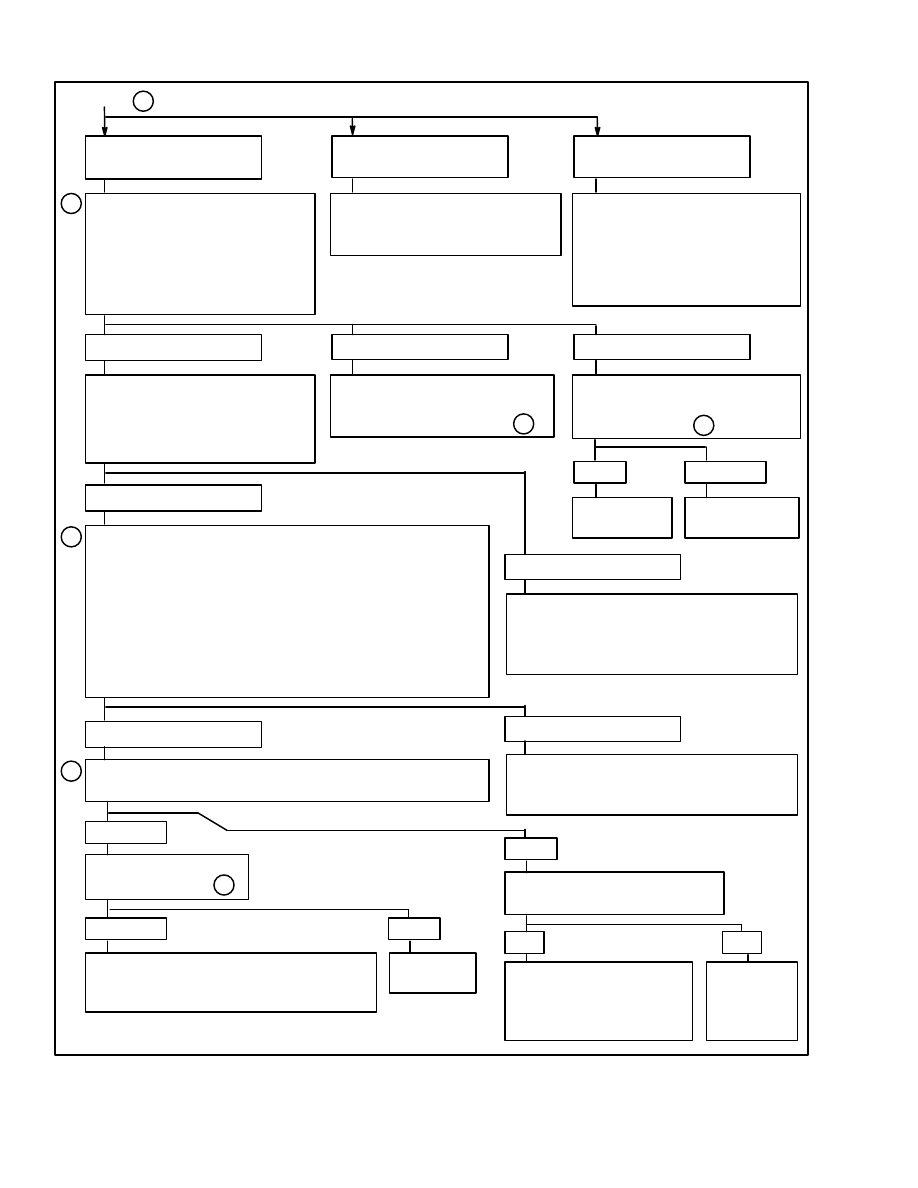
FIGURE 15. ELECTRONIC SPARK TIMING (EST) TROUBLESHOOTING CHART (1 of 2)
a. Turn the key switch to OFF.
b. Disconnect the 14–pin MSTS module connector.
c. Start the engine and run it at idle speed.
d. Check the voltage with a digital voltmeter from
terminal D of the 14–pin connector to ground. Is the
voltage 7 volts or greater?
EST is correct. Check for other faults in the
ignition system.
a. Stop the engine. Turn the key switch to ON.
b. Use the 1000 to 2000 range of the ohmmeter.
Check the resistance between terminal F of the
14–pin connector and ground. Is the resistance
less than 1500 ohms?
1
2
3
a. Turn the key switch to OFF.
b. Remove the initial timing connector from its
socket.
c. Install a timing light.
d. Start the engine.
e. Does the timing change when the engine speed
is increased from idle to approximately 1000 rpm?
Check circuit to D terminal on MSTS module for
the following faults:
a. bad connection.
b. open circuit or short–circuit to ground.
If a fault is not found in this step, replace the
ignition module.
Go to on next page.
4
YES
NO
YES
NO
YES
NO
Open circuit to terminal F on MSTS module or
a bad connection.
If a fault is not found in this step, replace the
ignition module.
Connect a test light to B+ and touch the probe
to terminal E of the 14–pin connector.

17
FIGURE 15. ELECTRONIC SPARK TIMING (EST) TROUBLESHOOTING CHART (2 of 2)
From
TEST LIGHT IS ON
TEST LIGHT IS OFF
4
a. Connect the ohmmeter between terminal F of the
14–pin connector and ground. Connect a test light to
B+ and touch the probe to terminal E of the 14–pin
connector.
b. When the test light is touched to terminal E, check
that the resistance on the ohmmeter changes from
less than 1500 ohms to greater than 2000 ohms.
Disconnect the 4–terminal connector at the
distributor. Check terminal E of the 14–pin
connector with the test light again.
NO
YES
The MSTS
module has a
fault.
The fault does not occur
regularly. Check for other
causes.
3
TEST LIGHT IS ON
TEST LIGHT IS OFF
The ignition module
has a fault.
NO
YES
Connect the ECM again. Start the engine and
run the engine at idle speed for one minute or
until the fault occurs again.
a. The ohmmeter is still connected between
terminal F of the 14–pin connector and ground.
b. Disconnect the 4–terminal connector at the
distributor. Does the resistance increase
greatly to indicate an open circuit?
5
6
YES
NO
Wire to terminal F
has a short–circuit.
Wire to terminal E or a
connection is open. If a
fault is not found in this
step, replace the ignition
module.
Wire to terminal E
has a short–circuit.
18
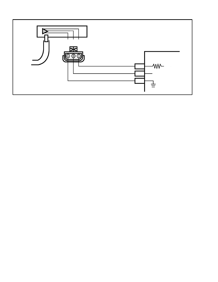
FIGURE 16. MAP SENSOR TROUBLESHOOTING
MSTS MODULE
J
H
M
MAP
SENSOR
A B C
MAP SIGNAL
SENSOR
GROUND
5 VOLT
REFERENCE
MANIFOLD ABSOLUTE PRESSURE
(MAP) SENSOR
Circuit Description
When the load on the engine changes, the pressure in the
intake manifold changes. This pressure is less than the
atmospheric pressure. The Manifold Absolute Pressure
(MAP) sensor measures the changes in the intake man-
ifold pressure and converts these changes to a voltage
signal. The MSTS module sends a reference signal (5.0
volts) to the MAP sensor. When the manifold pressure
changes, the electrical resistance of the MAP sensor
changes and a variation of the voltage signal is received
by the MSTS module.
When the engine is at idle speed and does not have a load
on it, the normal signal voltage from the MAP sensor is
approximately 1.0 to 1.5 volts. When the throttle valve
is fully opened, the intake manifold pressure is higher
(lower vacuum) and the signal voltage from the MAP
sensor is approximately 4.5 to 4.8 volts.
When the ignition switch is turned to ON, the initial
voltage signal from the MAP sensor indicates the baro-
metric pressure (BARO signal) to the MSTS module.
The MSTS module “remembers” the barometric pres-
sure (BARO signal) after the engine is running. The
MSTS module then automatically adjusts the ignition
timing for different altitudes and atmospheric condi-
tions.
Test Description
NOTE: If a malfunction indicates a fault in the MAP
sensor, make the following checks before doing tests on
the MAP sensor:
a. Make sure that the vacuum hose is not damaged.
Disconnect the vacuum hose from the MAP sen-
sor. Connect a vacuum gauge to the end of the
hose and start the engine. Check that the vacuum
indication from the engine to the MAP sensor is
correct. The engine will normally apply greater
than 34 kPa (10” Hg) of vacuum to the MAP sen-
sor.
b. If a malfunction indicates a fault in the MAP sen-
sor, make sure that the electrical connections do
not have dirt and corrosion. A bad electrical con-
nection can give an indication of a malfunction in
the MAP sensor.
NOTE: Make sure that the same digital voltmeter is
used for all measurements. The voltage and resistance
measurements must be carefully done. The differences
in measurements are small and the use of more than one
measuring instrument can give errors.
There are two tests in this procedure. The first test
checks the electrical signals between the MAP sensor
and the MSTS module. The second test checks the sig-
nal output of the MAP sensor when a standard vacuum is
applied to it.

19
Test 1. Do the following test procedure:
a. The key switch is OFF. Disconnect the connector
from the MAP sensor. The engine is stopped and
the key switch is ON. Connect a digital voltmeter
between terminal A and terminal C the plug con-
nector. Terminal C is the 5 volt reference voltage
and terminal A is the sensor ground. Carefully
measure the actual reference voltage (“5V REF-
ERENCE”) between the two terminals.
b. Use a barometer or call a local weather station to
find the local atmospheric pressure. Find the
number in the “Atmospheric Pressure” column in
the chart that is the closest to the atmospheric
pressure. See TABLE 1.
c. Find the “5V REFERENCE” column in the chart
that is closest to the actual reference voltage mea-
sured in step a. Follow the “5V REFERENCE”
column into the signal voltage area until it inter-
sects with the horizontal column for “Atmo-
spheric Pressure” that was found in step b. Make
a note of the “MAP Sensor Signal Voltage” where
the two columns intersect.
d. Three jumper wires are needed so that the voltage
can be measured when the connector to the wir-
ing harness is connected to the MAP sensor. Use
the jumper wires to connect the terminals A, B,
and C to their connections in the wiring harness.
e. Connect the “+” probe of the digital voltmeter to
terminal B (MAP signal voltage). Connect the
negative (or COMM) probe to terminal A (sensor
ground).
f. The engine is stopped and the key switch is ON.
Measure the MAP sensor signal voltage. The
voltage must be within +0.4 volts of the voltage
value found on the chart in step c. If the voltage is
not within these limits, replace the MAP sensor.
Test 2. The jumper wires must be installed as described
in Test 1, step d. The voltmeter must be connected as de-
scribed in Test 1, step e. Do the following procedure:
a. Disconnect the vacuum hose at the MAP sensor
and install a plug in the hose. Connect a vacuum
pump that can be operated by hand to the MAP
sensor.
b. Start the engine and run the engine at idle speed.
c. Use the vacuum pump to apply 34 kPa (20” Hg)
of vacuum to the MAP sensor. (See the PRES-
SURE CONVERSION CHART at the end of this
section.) Look at the voltage change indicated on
the voltmeter. The voltage change will normally
occur as quickly as the vacuum is applied to the
MAP sensor.
d. Compare the voltage indicated on the voltmeter
with the voltage indicated in Test 1, step f. The
correct voltage indicated in this step will be 1.2 to
1.3 volts less that the voltage indicated in Test 1,
step f.
e. If the voltage signals are correct, check for vacu-
um leaks in the hoses and connections. If the volt-
age signals are not correct, replace the MAP sen-
sor.

20
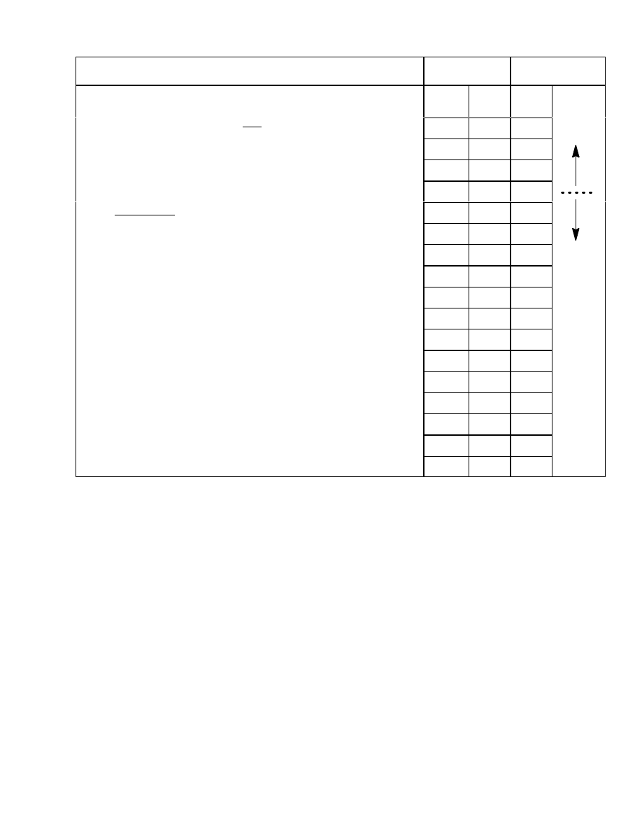
TABLE 1. VOLTAGE AND PRESSURE FOR MAP SENSOR TROUBLESHOOTING
ATMOSPHERIC
5 VOLT REFERENCE
ATMOSPHERIC
PRESSURE
4.80
4.90
5.00
5.10
5.20
kPa
inches of Hg
MAP SENSOR SIGNAL VOLTAGE
64.35
19.0
2.75
2.80
2.86
2.92
2.97
66.04
19.5
2.83
2.89
2.95
3.01
3.07
67.73
20.0
2.92
2.98
3.04
3.10
3.16
69.43
20.5
3.00
3.07
3.13
3.19
3.25
71.12
21.0
3.09
3.15
3.22
3.28
3.35
72.81
21.5
3.18
3.24
3.31
3.37
3.44
74.51
22.0
3.26
3.33
3.40
3.47
3.53
76.20
22.5
3.35
3.42
3.49
3.56
3.63
77.89
23.0
3.43
3.51
3.58
3.65
3.72
79.59
23.5
3.52
3.59
3.67
3.74
3.81
81.28
24.0
3.61
3.68
3.76
3.83
3.91
82.97
24.5
3.69
3.77
3.85
3.92
4.00
84.67
25.0
3.79
3.86
3.94
4.01
4.09
86.36
25.5
3.86
3.94
4.03
4.11
4.19
88.05
26.0
3.95
4.03
4.11
4.20
4.28
89.75
26.5
4.04
4.12
4.20
4.29
4.37
91.44
27.0
4.12
4.20
4.29
4.38
4.47
93.13
27.5
4.21
4.30
4.38
4.47
4.56
94.83
28.0
4.29
4.38
4.47
4.56
4.65
96.49
28.5
4.38
4.47
4.56
4.65
4.75
98.19
29.0
4.47
4.56
4.65
4.75
4.84
99.88
29.5
4.55
4.65
4.74
4.84
4.93
101.57
30.0
4.64
4.74
4.83
4.93
5.03
103.27
30.5
4.72
4.84
4.92
5.02
5.12
104.96
31.0
4.81
4.91
5.01
5.11
5.21
21
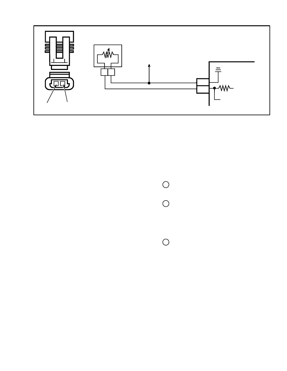
FIGURE 17. ECT SENSOR TROUBLESHOOTING
MSTS MODULE
M
G
ENGINE COOLANT
SENSOR
B A
SENSOR
GROUND
ECT SIGNAL
5 VOLT
REFERENCE
INITIAL TIMING
CONNECTOR
B
A
B
A
ENGINE COOLANT TEMPERATURE
SENSOR (ECT)
NOTE: This troubleshooting is normally used only if
there is a problem when the engine coolant is cold. A
fault in the ECT normally causes a problem before the
engine coolant has increased to operating temperature.
The problem can be a short delay when the throttle is
opened or a decrease in engine power.
Circuit Description (See FIGURE 17.)
The Engine Coolant Temperature sensor (ECT) uses a
thermistor to control the signal voltage to the MSTS
module. The MSTS module (terminal G) applies a
5–volt reference voltage to the ECT. When the engine
coolant is cold, the thermistor resistance is higher than
when the engine coolant is at operating temperature. As
the temperature of the engine coolant increases after the
engine is started, the resistance decreases and the signal
voltage decreases. When the engine is operating at 85 to
95
°
C (185 to 203
°
F), the signal voltage is approximate-
ly 1.5 to 2.0 volts.
Test Description (See FIGURE 18.)
The numbers in circles on the troubleshooting chart
have the following indications:
1 This step checks if there is a fault in the wiring or
the MSTS module or if the fault is in the ECT.
2 Make sure the electrical connections do not have
dirt and corrosion. If an ohmmeter is connected
across the terminals A and B of the ECT, the resis-
tance normally decreases as the temperature of
the engine coolant increases.
3 This step checks if there is a fault in the wiring to
the ECT or the sensor ground.
22
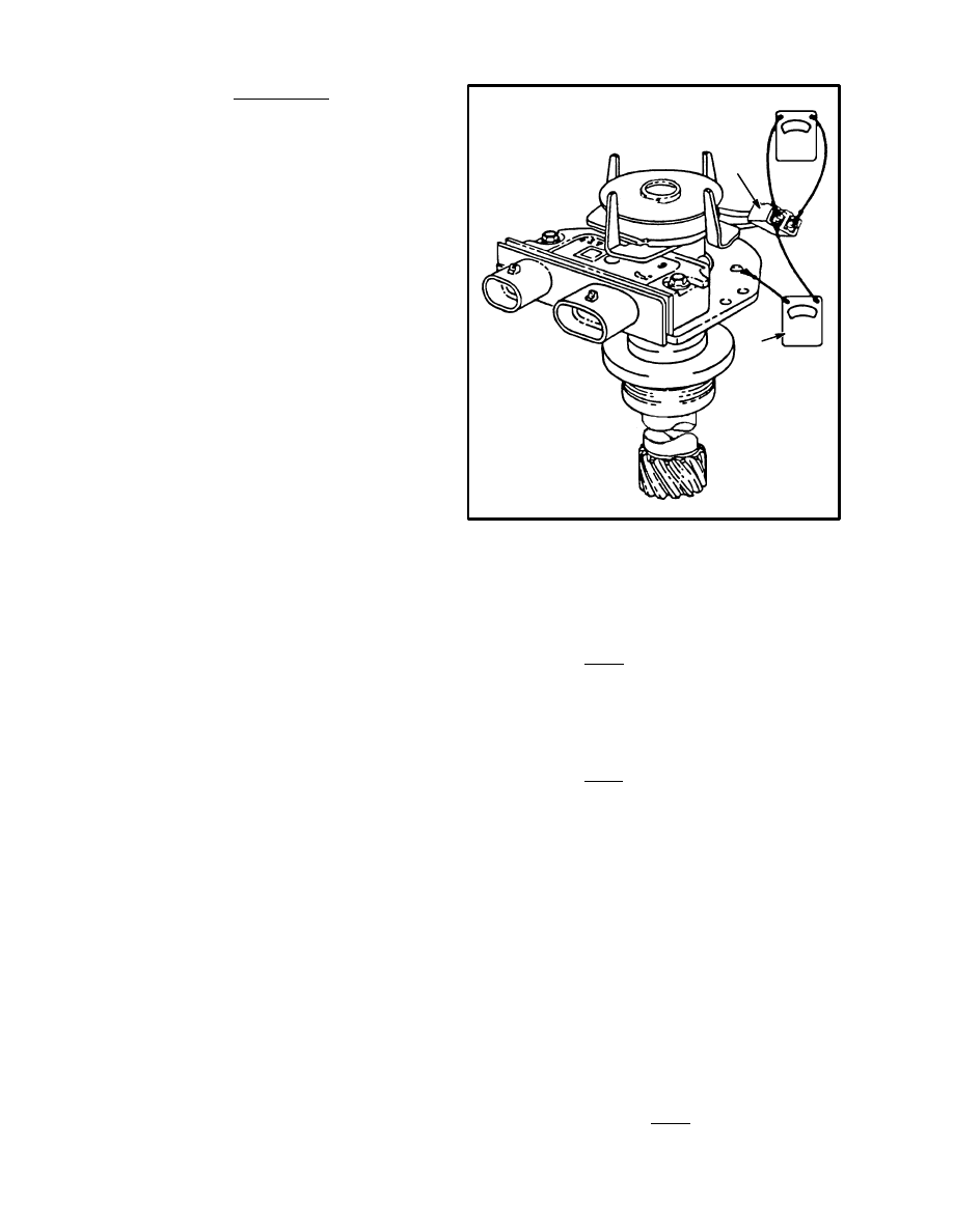
FIGURE 18. ENGINE COOLANT TEMPERATURE SENSOR TROUBLESHOOTING CHART
a. Connect the “+” probe of the digital
voltmeter to terminal B (5V signal circuit)
on the connector.
b. Connect the negative (COMM) probe
to a good ground connection on the
engine. Check that the voltage signal is
greater than 4 volts.
There is a bad connection or the ECT has a
fault. Make repairs.
a. Remove the voltmeter.
b. Turn the key switch to ON.
c. Connect a test light to battery voltage B+.
d. Touch the probe of the test light to
terminal B on the connector to the ECT.
Check that the test light illuminates.
1
3
a. Turn the key switch to OFF.
b. Disconnect the connector at the ECT.
c. Turn the key switch to ON.
d. Connect a digital voltmeter across the two
terminals of the connector to the ECT. Check
that the voltage signal is greater than 4 volts.
Open circuit in the sensor ground
or
bad connection at the MSTS module
or
fault in the MSTS module. Make repairs as
necessary.
YES
NO
YES
NO
YES
NO
Circuit for 5V signal is open
or
bad connection at the MSTS module
or
fault in the MSTS module. Make repairs as
necessary.
2
Disconnect the MSTS module. Is the test light
still illuminated?
YES
NO
Circuit for 5V
signal has a
short–circuit.
Circuit for 5V signal has
a short–circuit to
sensor ground
or
there is a fault in the
MSTS module. Make
repairs as necessary.
COOLANT SENSOR
OHMS
°
C
°
F
100
210
185
70
160
450
38
100
1,800
20
70
3,400
4
40
7,500
–7
20
13,500
–18
0
25,000
–40
–40
1,000,700
TEMPERATURE TO RESISTANCE VALUES
(APPROXIMATE)

23
REPAIRS
NOTE: This REPAIR section describes the components
of the MSTS and how to remove or replace them.
DISTRIBUTOR
A distributor with a separate ignition coil is used on all
MSTS engines. The ignition coil is connected to the ro-
tor in the distributor through a high voltage wire. The
operation of the ignition module and the magnetic pulse
generator is described under OPERATION at the begin-
ning of this section.
When the current in the primary circuit of the ignition
coil quickly decreases, the induction in the secondary
circuit sends a high voltage pulse (35 000 volts) to the
rotor in the distributor. The rotor is aligned with one of
the leads to a spark plug wire and this high voltage pulse
is sent to one of the spark plugs.
Removal
CAUTION
Carefully lift and release the lock tabs on the connec-
tors to the distributor. The lock tabs can be easily
broken if too much force is applied with a screwdriv-
er or other tool.
Never permit the TACH CONN. terminal to touch
ground. The ignition module or the ignition coil can
be damaged.
1. Disconnect the battery negative (ground) cable.
2. If removal of the spark plug wires are not required for
the repairs, leave them connected to the distributor cap.
Remove the two capscrews that fasten the distributor
cap to the distributor. Move the distributor cap away
from the work area.
3. Disconnect the distributor 4–terminal connector.
4. Disconnect the ignition coil connector.
5. Remove the bolt and clamp that hold the distributor in
the engine. Make a note of the positions of the rotor to
distributor housing and the distributor to the engine.
Slowly pull the distributor from the engine until the ro-
tor just stops turning counterclockwise and make a note
of the position of the rotor. This position must be used
when the distributor is installed again.
Disassembly (See FIGURE 19.)
1. Remove the rotor (2). Make a match mark on the gear
(6) and the shaft (3) so that can be assembled in the same
position.
2. Use a punch to remove the roll pin (5) from the shaft
(3).
3. Remove the gear (6).
4. Remove the shaft (3) with the timer core from the
housing (8).
5. Remove the retainer (4) from the housing (8). Use a
screwdriver as a prybar.
6. Disconnect the sensing coil (12) from the ignition
module (9).
CAUTION
Carefully lift and release the lock tab on the connec-
tor to the sensing coil. The lock tab can be easily bro-
ken if too much force is applied with a screwdriver or
other tool.
7. Use a screwdriver to lift the lock tab. Remove the
sensing coil (12).
8. Remove the two screws that hold the ignition module
(9) in the housing. Remove the ignition module.
Inspection
Inspect the shaft for a loose fit between the shaft and its
bushing in the housing. If the bushing or the shaft is
worn so that the shaft moves from side to side in the
bushing, replace the shaft or the housing.
Inspect the housing for cracks or damage.
Assembly (See FIGURE 19.)
1. Apply silicon grease to the bottom of the ignition
module (9). Install the ignition module into the housing
(8) and tighten the two screws.
NOTE: Hyster Part No. 304408 is a silicon bearing
grease used between electronic components and their
heat sinks. A small container of silicon grease is en-
closed in the package with a new ignition module.
2. Install the sensing coil (12). The tab on the bottom of
the sensing coil fits into the anchor hole in the housing
(8).
24
3. Connect the sensing coil to the ignition module. Make
sure that the lock tab on the connector is fastened.
4. Install the retainer (4).
5. Install the shaft assembly (3) into the housing (8).
6. Install the seal (7) on the housing. Install the gear (6)
on the end of the shaft.
7. Align the marks on the gear and shaft. Install the roll
pin (5). Turn the shaft assembly and make sure the teeth
of the timer core on the shaft assembly do not touch the
pole piece.
8. Install the rotor (2) on the shaft.
Installation
1. Put the rotor and distributor in the same position as it
was removed from the engine.
If the engine has been rotated after the distributor was
removed, the following procedure must be used before
the distributor is installed again:
a. Remove the No. 1 spark plug.
b. Put a finger over the No. 1 spark plug hole and
slowly rotate the engine until pressure is felt on
the compression stroke.
c. Align the timing mark on the crankshaft pulley to
0
°
(TDC) on the engine timing indicator.
d. Turn the distributor rotor to point between the po-
sitions on the distributor cap for No. 1 and No. 4
spark plug leads.
e. Install the distributor in the engine. The rotor and
shaft will rotate a few degrees when the gear on
the distributor shaft engages the drive gear on the
engine cam. The timing is correct if the rotor
points at the position on the distributor cap for the
No. 1 spark plug lead.
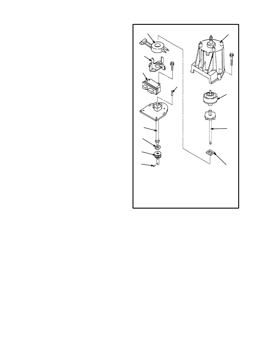
FIGURE 19. DISTRIBUTOR
1. CAP
2. ROTOR
3. SHAFT/
TIMER CORE
4. RETAINER
5. PIN
6. DRIVE GEAR
1
2
3
4
5
6
7. SEAL
8. HOUSING
9. MODULE
10. ALIGNMENT PIN
11. POLE PIECE
12. COIL
7
8
9
10
11
12
2. Install the clamp and bolt. Tighten the bolt with your
hand.
3. Install the distributor 4–terminal connector.
4. Install the ignition coil connector.
5. Install the distributor cap and the two capscrews. If
the spark plug wires were removed. install them in the
correct sequence.
6. Connect the battery negative cable.
7. Start the engine and check the engine timing. See the
following paragraphs about “Ignition Timing”.
8. Tighten the bolt for the distributor clamp to 43 N.m
(25 lb
f
ft).
25
Ignition Timing
1. Disconnect the initial timing connector.
2. Connect a timing light to the No. 1 spark plug wire.
WARNING
Do not touch moving parts (fan, belt, shafts, pulleys).
3. Run the engine at 1200 rpm. The correct setting for
the initial timing set point is 8
°
BTDC.
4. Check for the correct timing. If the timing is not cor-
rect, loosen the clamp that holds the distributor housing.
Rotate the housing right or left to get the correct timing.
Tighten the clamp when the timing is correct.
5. If necessary, check and adjust the idle speed at the car-
buretor.
IGNITION MODULE
Test For A Fault (See FIGURE 20.)
NOTE: The ignition module can be checked in the dis-
tributor. A test light and three jumper wires are needed
to make the tests. The battery in the vehicle must be fully
charged so that the starter rotates the engine at the nor-
mal speed.
1. Disconnect the 4–terminal connector from the distrib-
utor. Use two jumper wires between the distributor and
the 4–terminal connector to connect the following cir-
cuits:
REFERENCE (Purple)
GROUND (Black)
2. Connect the test light to a 12 volt positive source. Start
the engine. Touch the probe of the test light to pin B in
the 4–terminal connector on the distributor. When 12
volts are applied through the test light to pin B (BY–
PASS), the ignition module changes to EST mode. The
EST connection (pin D) is open and the engine will nor-
mally stop. This step checks the BY–PASS operation of
the ignition module.
3. Use a jumper to connect pin D (EST) to pin C (REF-
ERENCE) at the distributor. Apply 12–volts through the
test light to pin B (BY–PASS) as described in step 2.
Start the engine. If the engine starts, this step checks that
the EST circuit in the ignition module is good.
4. Remove the test light from pin B (BY–PASS) while
the engine is running. If the engine stops, this check
shows that the ignition module internally changes the
EST circuit to ground. Since there is a jumper wire be-
tween pin D (EST) to pin C (REFERENCE), the REF-
ERENCE signal is also sent to ground and the engine
stops.
A B C D
G B R E
+
C
P N
D
E
F
K
TO
IGN
FIGURE 20. IGNITION SYSTEM TROUBLESHOOTING
C
A B
D
EST
REFERENCE
BY–PASS
TACH
CONN.
+
C
IGN
IGNITION
MODULE
MSTS
MODULE
DISTRIBUTOR
4–TERMINAL
CONNECTOR
SENSING
COIL
TACHOMETER
CONNECTOR
IGNITION
COIL
IGNITION COIL
CONNECTOR
TO
DISTRIBUTOR
26
5. If any tests described in steps 2, 3, or 4 do not work as
indicated, check the wiring harness for a short–circuit or
an open circuit. If the wiring harness is good, replace the
ignition module.
6. When the tests are complete, connect the system for
normal operation.
Ignition Module Replacement
1. Remove the distributor cap and rotor.
2. Remove the two screws that hold the ignition module
in the distributor.
3. Lift the ignition module and disconnect the connec-
tions. Make a note of the connections so that they can be
correctly connected again. Remove the ignition module
from the distributor.
NOTE: Do not remove the silicon grease from the igni-
tion module or the distributor if the same ignition mod-
ule will be installed again. If a new ignition module is
installed, a small container of silicon grease is in the
package. Clean the old silicon grease and apply a new
layer of silicon grease to both the ignition module and
the distributor housing. This silicon grease is necessary
for cooling the ignition module.
4. Connect the connectors in the distributor to the igni-
tion module. Make sure the connectors are the same as
when they were removed.
5. Install the ignition module in the distributor.
6. Install the two screws that fasten the ignition module
in the distributor.
7. Install the distributor cap and rotor.
SENSING COIL
Test For A Fault
1. Disconnect the battery negative cable.
FIGURE 21. TEST THE SENSING COIL
1. SENSING COIL
CONNECTIONS
2. OHMMETER
1
2
STEP 1.
STEP 2.
2. Remove the distributor cap. Disconnect the connec-
tion from the sensing coil to the ignition module.
3. Check the resistance of the sensing coil with an ohm-
meter. Connect ohmmeter to the sensing coil connec-
tions as shown in step 1 of FIGURE 21. Check the resis-
tance between both connections and ground. The ohm-
meter will indicate infinity for both connections, if the
sensing coil is good.
4. Connect ohmmeter across both sensing coil connec-
tions as shown in step 2 of FIGURE 21. If the ohmmeter
does not indicate 500 to 1500 ohms, replace the sensing
coil. Check the wires for a loose connection.
Sensing Coil Replacement
Remove and disassemble the distributor as described in
the repairs for the DISTRIBUTOR.
IGNITION COIL
Test For A Fault
1. Disconnect the battery negative (ground) cable.
2. Disconnect the high voltage wire.
3. Disconnect the connectors at the ignition coil.
4. Set the ohmmeter on one of the higher scales. Connect
the ohmmeter as shown in step 1 of FIGURE 22. If the
27
ohmmeter indication is less than infinity, install a new
ignition coil.
5. Set the ohmmeter on one of the low scales. Connect
the ohmmeter as shown in step 2 of FIGURE 22. If the
ohmmeter indication is greater than zero to one ohm, in-
stall a new ignition coil.
6. Set the ohmmeter on one of the middle scales. Con-
nect the ohmmeter as shown in step 3 of FIGURE 22. If
the ohmmeter indication is infinity (open circuit), install
a new ignition coil.
Removal
1. Turn the key switch to “OFF”. Apply the parking
brake.
2. Disconnect the negative battery cable.
3. Put tags for identification on the connectors and dis-
connect them from the coil.
FIGURE 22. IGNITION COIL
1. CLEAN METAL FOR GROUND CONNECTION
2. OHMMETER
3. C– AND TACH CONNECTOR
4. B AND + TERMINALS
1
2
3
4
STEP 1.
STEP 2.
STEP 3.
CAUTION
Do not damage the high voltage wires (spark plug
wires) during removal. Hold the wire by the boot
near the end of the wire. Rotate the boot before pull-
ing it and the connection from the terminal.
4. Remove the high voltage wire.
5. Remove the nuts (or capscrews) that fasten the brack-
et for the ignition coil to the engine.
6. Remove the ignition coil and bracket assembly from
the engine.
7. Use a drill and punch to remove the two rivets that fas-
ten the bracket to the coil.
Installation
1. Install the original bracket on the replacement coil us-
ing screws (supplied with replacement coil).
2. Install the ignition coil assembly on the engine with
nuts (or capscrews).
3. Install the control wire connectors and the high volt-
age wire on the ignition coil.
4. Connect the negative (ground) battery cable.
MSTS MODULE
NOTE: See the TROUBLESHOOTING descriptions to
check the operation of the MSTS module. The follow-
ing paragraphs describe the removal and installation of
the MSTS module.
CAUTION
Never connect or disconnect the wiring harness at
the MSTS module when the key switch is “ON”. Nev-
er connect jumper wires or test instruments to the
MSTS module when the key switch is “ON”. The best
procedure is to disconnect the battery negative cable
when removing or installing electrical components.
Do not touch the connector pins or the soldered con-
nections on the circuit board. The MSTS module can
be damaged with an electrostatic discharge.
Removal
1. Disconnect the battery negative cable. Disconnect the
14–pin connector at the MSTS module.
28
2. Remove the three bolts that fasten the MSTS module
to its mount. Remove the MSTS module.
Installation
1. Install the MSTS module on its mount surface and in-
stall the three bolts.
2. Connect the 14–pin connector at the MSTS module.
Connect the battery negative cable.
FIGURE 23. MSTS MODULE
PNMLKJH
GFEDCBA
14–PIN CONNECTOR
ECT SENSOR REPLACEMENT
(See FIGURE 24.)
NOTE: See the TROUBLESHOOTING descriptions to
check the operation of the ECT sensor. The following
paragraphs describe the disconnection or the removal
and installation of the ECT sensor.
FIGURE 24. ENGINE COOLANT
TEMPERATURE SENSOR (ECT)
1. TEMPERATURE SENSOR
2. ELECTRICAL CONNECTOR
3. LOCK TAB
2
1
3
1. Disconnect the battery negative cable. Disconnect the
connector at the ECT sensor.
2. Use a wrench and carefully loosen the ECT from the
coolant manifold.
3. Install the ECT in its hole in the coolant manifold and
carefully tighten it with a wrench.
4. Connect the connector at the ECT. Connect the bat-
tery negative cable.
MAP SENSOR REPLACEMENT
(See FIGURE 25.)
NOTE: The MAP sensor is on the left–hand side of the
bracket that is on top of the valve cover.
1. Disconnect the battery negative cable. Disconnect the
vacuum hose from the MAP sensor. Disconnect the
electrical connector at the MAP sensor.
2. Remove screws that fasten the MAP to its mount. Re-
move the MAP sensor.
3. Install the MAP sensor on its mount surface and in-
stall the screws.
4. Connect electrical connector at the MAP sensor. Con-
nect the vacuum hose to the MAP sensor. Connect the
battery negative cable.
FIGURE 25. MANIFOLD ABSOLUTE
PRESSURE (MAP) SENSOR
2
1
1. SENSOR
2. ELECTRICAL CONNECTOR
29
PRESSURE CONVERSION CHART
ABSOLUTE
PRESSURE
GAUGE
PRESSURE
Vacuum and pressure readings often cause confusion because
everyone does not use the same point of reference. “Absolute
kPa
Inches
of Hg
Inches
of Hg
everyone does not use the same point of reference. Absolute
pressure” is the “gauge pressure” plus the atmospheric pressure.
The standard atmospheric pressure is also called the standard
121.92
36
6
Pressure
The standard atmospheric pressure is also called the standard
barometric pressure and is equal to 101.325 kPa (14.695 psi) or
[29 92 inches of mercury (Hg)] at sea level The reference point for
115.14
34
4
Pressure
[29.92 inches of mercury (Hg)] at sea level. The reference point for
these measurements is zero pressure or an absolute vacuum.
108.4
32
2
these measurements is zero pressure or an absolute vacuum.
Service people normally use “gauge pressure” as the reference point
101.6
30
0
Service people normally use gauge pressure as the reference point
which does not add the atmospheric pressure. The reference point
for “gauge pressure” is atmospheric pressure It is important to know
94.8
28
2
for “gauge pressure” is atmospheric pressure. It is important to know
when reading a pressure chart whether the units are given in
“ b
l t
”
“
”
88.0
26
4
V
g
p
g
“absolute pressure” or “gauge pressure”.
81.3
24
6
Vacuum
The gauges used by most service people indicate “gauge pressure”.
However most gauges calibrated in a metric scale (kilopascals) and
74.51
22
8
However, most gauges calibrated in a metric scale (kilopascals) and
used to measure less than atmospheric pressure normally indicate
b
l t
h
i th
h t A
lib t d i
67.73
20
10
p
p
y
absolute pressure as shown in the chart. A gauge calibrated in
inches of Hg and used to measure a vacuum begins at zero and
60.96
18
12
inches of Hg and used to measure a vacuum begins at zero and
increases its indication as the vacuum increases as shown in the
“gauge pressure” column of the chart.
54.18
16
14
“gauge pressure” column of the chart.
An additional cause of confusion is that the manifold pressure gauge
47.41
14
16
An additional cause of confusion is that the manifold pressure gauge
for an engine with a turbocharger is normally calibrated for absolute
40.64
12
18
for an engine with a turbocharger is normally calibrated for absolute
pressure for both kilopascals and inches of Hg. The Manifold
Absolute Pressure (MAP) sensor described in this section is also
33.87
10
20
Absolute Pressure (MAP) sensor described in this section is also
calibrated for absolute pressure, but the service person doing
checking or troubleshooting will often be using gauges calibrated for
27.09
8
22
checking or troubleshooting will often be using gauges calibrated for
“gauge pressure”.
20.32
6
24
gauge pressure .
13.55
4
26
Document Outline
- INTRODUCTION
- TROUBLESHOOTING
- REPAIRS
Wyszukiwarka
Podobne podstrony:
897844 2200SRM0603 (01 1996) UK EN
897856 2200SRM0612 (01 1996) UK EN
897070 2200SRM0288 (01 1994) UK EN
897415 2200SRM0464 (01 1994) UK EN
897495 2200SRM0514 (01 2004) UK EN
1564268 2200SRM1106 (01 2004) UK EN
1595265 2200SRM1204 (01 2005) UK EN
897928 2200SRM0625 (12 1996) UK EN
1556871 2200SRM1105 (01 2004) UK EN
więcej podobnych podstron