
1
EV–100 MOTOR CONTROLLER
REPAIRS AND ADJUSTMENTS
GENERAL
This section has information for making repairs and ad-
justments for faults found in the Troubleshooting sec-
tion. The EV–100 motor controller, used to control the
operation of electric lift trucks, is made for Hyster Com-
pany by the General Electric Company.
NOTE: This section does not include the EV–100LX/
ZX and EV–200LX/ZX series of motor controllers. See
the section EV–100LX/ZX AND EV–200LX/ZX
MOTOR CONTROLLERS, 2200 SRM 460, for in-
formation on these series of motor controllers.
Most of the components of the EV–100 motor controller
can not be repaired, but must be replaced. This section
describes the procedures for checking or replacing the
components of the motor controller.
There are many electrical components that are not part
of the motor controller, but give input signals to it. These
components include the following:
a. Key switch
b. START switch
c. Brake switch
d. Foot switch
e. Seat switch
f. Direction (FORWARD and REVERSE) switches
g. Accelerator potentiometer
h. Guidance and steering systems
The checks and repairs for these components are in other
sections. Many of these components are adjusted during
installation. See the following sections to check, repair,
or adjust these components:
ELECTRICAL CHECKS AND ADJUST-
MENTS FOR SitDrive
LIFT ELECTRIC
TRUCKS, 2200 SRM 464
ELECTRICAL ADJUSTMENTS, 2200
SRM 381 for the N40–50EA, N40–45ER
ELECTRICAL SYSTEM ADJUSTMENTS,
2200 SRM 420 for the R30E, R30EA, and
R30EF
ELECTRICAL CHECKS AND ADJUST-
MENTS, 2200 SRM 406 for the R40EH
See the section BATTERY INDICATORS, 2200
SRM 138 to adjust or replace the battery indicator. See
the section INSTRUMENT PANEL INDICATORS
AND SENDERS, 2200 SRM 143 to check and replace
the other instrument panel indicators and the senders.
WARNING
Do not operate a lift truck that needs adjustment or
repairs. Report the need for adjustment or repairs
immediately. If adjustment or repair is necessary,
put a “DO NOT OPERATE” tag in the operator’s
area. Remove the key from the key switch.
Some of the checks and adjustments are done with
the battery connected. Never have any metal on your
fingers, arms or neck. These metal items can acci-
dentally make an electrical connection and cause an
injury.
Some voltage measurements must be made with the
SRO circuit complete. Make sure the drive wheels
are raised from the surface before doing
troubleshooting. See the OPERATING MANUAL
or the Preventive Maintenance section for your lift
truck to raise the drive wheels. If you are working
alone, put a weight in the seat to close the seat switch.
If your lift truck has a seat brake, use a block behind
the lower actuator bar to release the seat brake when
the operator in not in the seat. Put the voltmeter so
that you can see it from the operator area. You can
operate the controls with your hand and also make
the voltage measurements.
Make sure you disconnect the battery and separate
the connector before you disassemble any part of the
controller. The capacitor stores electrical energy and
cause injury if a person discharges a capacitor
through parts of the body. AFTER the battery is dis-
connected, make sure you also discharge the capaci-
tor C1 by putting a metal bar (screwdriver or similar
tool) across the two connections of the capacitor.
2
11482
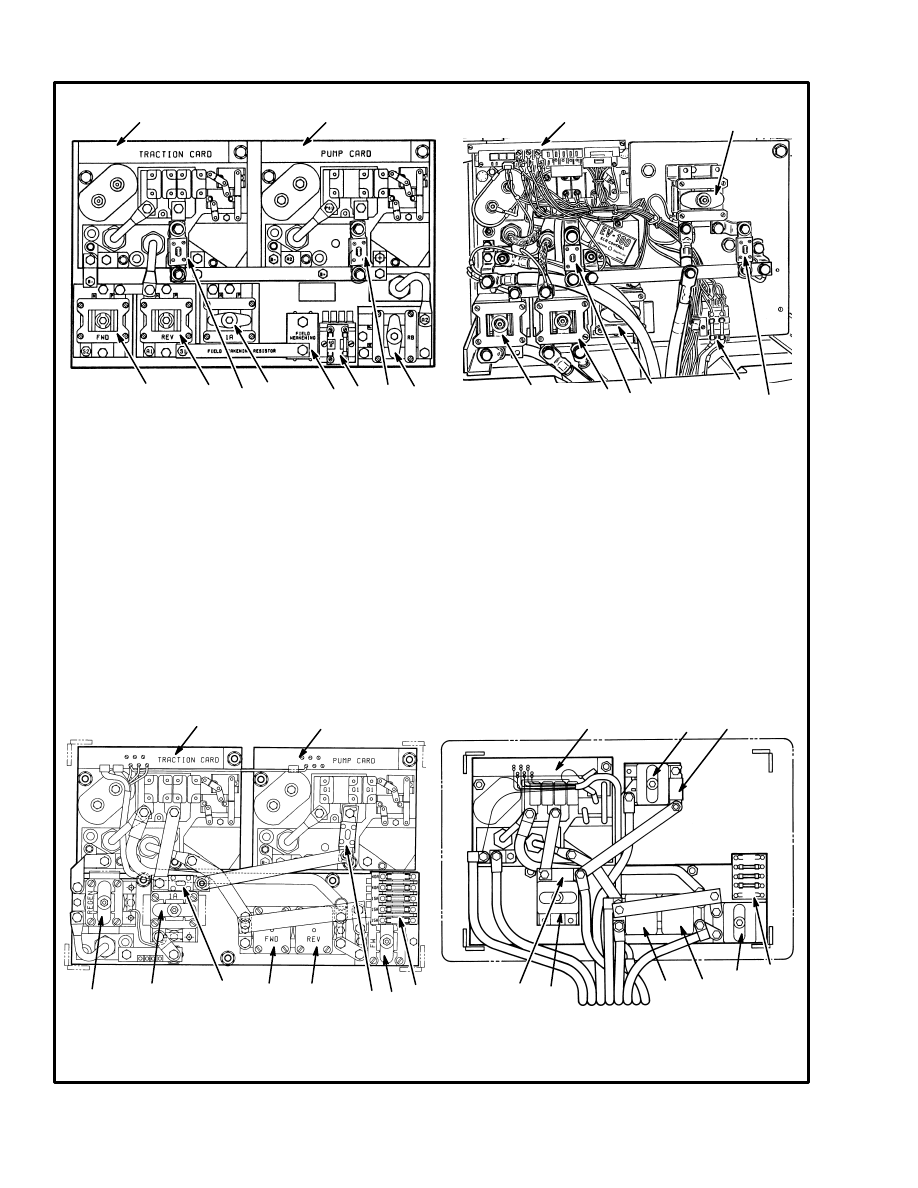
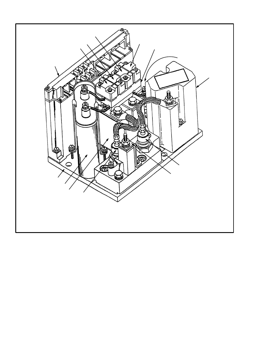
FIGURE 1. TYPICAL COMPONENT LOCATIONS OF THE EV–100 CONTROLLER
1. TRACTION CARD REGENERATIVE BRAKING
2. TRACTION CARD WITHOUT REGENERATIVE
BRAKING
3. EV–100 CONTROL, HYDRAULIC PUMP MOTOR
4. CONTACTOR, HYDRAULIC PUMP MOTOR
5. CONTACTOR, REGENERATIVE BRAKING
6. CONTACTOR, 1A
11531
MOTOR CONTROLLER WITH REGENERA-
TIVE BRAKING, 1A BY–PASS, AND SCR
CONTROLLER FOR HYDRAULIC PUMP
MOTOR CONTROLLER WITH 1A BY–PASS,
AND CONTACTOR CONTROL FOR HYDRAU-
LIC PUMP
7. CONTACTOR, FORWARD DIRECTION
8. CONTACTOR, REVERSE DIRECTION
9. CONTACTOR, FIELD WEAKENING
10. FUSE, TRACTION CIRCUIT
11. FUSE, HYDRAULIC PUMP
12. FUSES, CONTROL CIRCUIT AND
STEERING
3
1
2
4
9
8
7
6
5
7
8
6
10
11
12
11
10
12
BEFORE NOVEMBER 1987
12173
12124
1
2
3
4
MOTOR CONTROLLER WITH REGENERA-
TIVE BRAKING, 1A BY–PASS, AND SCR
CONTROLLER FOR HYDRAULIC PUMP
MOTOR CONTROLLER WITH 1A BY–PASS,
AND CONTACTOR CONTROL FOR HYDRAU-
LIC PUMP
5
6
6
7
7
8
8
9
9
10
11
12
12
10
11
AFTER NOVEMBER 1987
3
CAUTION
Correct meter polarity is necessary for some checks.
Meter correct positive is indicated as (+). Meter cor-
rect negative is indicated as (–).
Use a meter with a minimum rating of 20 000 ohms
per volt to make measurements. Most digital volt
meters are good.
NOTE: The electronic controller can not be seen from
the operator area. Some checks and adjustments are dif-
ficult to do unless another person can operate the con-
trols.
NOTE: The configuration of the controller was
changed during November 1987. The operation of the
controller is still the same, but some power connections
and the location of some contactors were changed. All
of the components are on a base plate mount in the ear-
lier configuration. Two arrangements for the SitDrive
series of lift trucks are shown in FIGURE 1. The later
configuration for the SitDrive
series of lift trucks and
the R30E/EA/EF Orderpicker
have a separate base
plate for three groups:
1. Traction controller group
2. Contactor group
3. Controller group for the hydraulic pump. (If the
SCR controller for the hydraulic pump is not
used, a single contactor for the hydraulic pump is
installed in that position.)
If the SCR controller for the hydraulic pump is not used,
a single contactor for the hydraulic pump is installed in
that location.
NOTE: Most of the bolts and screws connected to the
contactor assemblies are inch (SAE) in the controllers
manufactured before November 1987. The bolts and
screws in the controllers manufactured after November
1987 are metric sizes. The bolts and screws connected to
the electronic components are normally metric sizes.
Make sure that you use the correct fastener for the part
that has been disassembled.
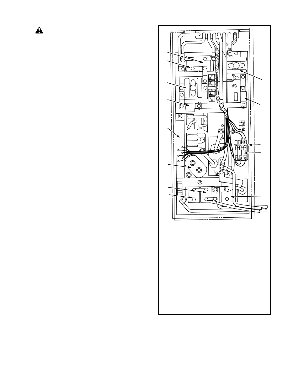
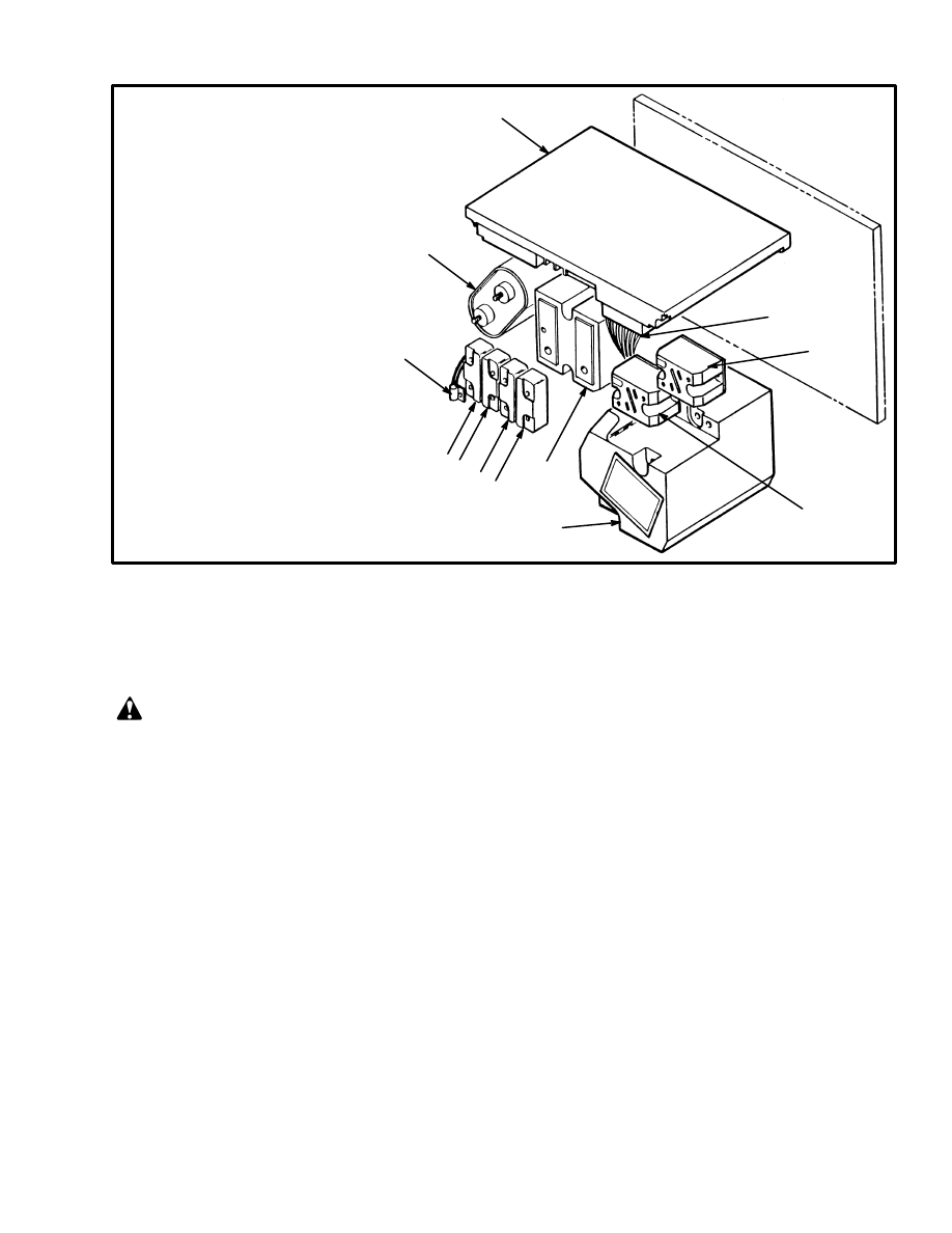
FIGURE 2. COMPONENT LOCATIONS, J25–35B
11740
EV–100 MOTOR CONTROLLER
FOR J25–35B
8
1
2
3
4
5
6
9
10
11
12
13
1. CONTROL CARD
2. CAPACITOR C1
3. LEFT FORWARD CONTACTOR
4. LEFT REVERSE CONTACTOR
5. BALANCE CONTACTOR
6. FUSES, CONTROL CIRCUIT AND
STEERING
7. ELECTRONIC DRIVERS (PMT, 1A, D)
8. FUSE, HYDRAULIC PUMP
9. HYDRAULIC PUMP CONTACTOR
10. RIGHT REVERSE CONTACTOR
11. RIGHT FORWARD CONTACTOR
12. CONTACTOR 1A
13. FUSE, TRACTION CIRCUIT
7
4
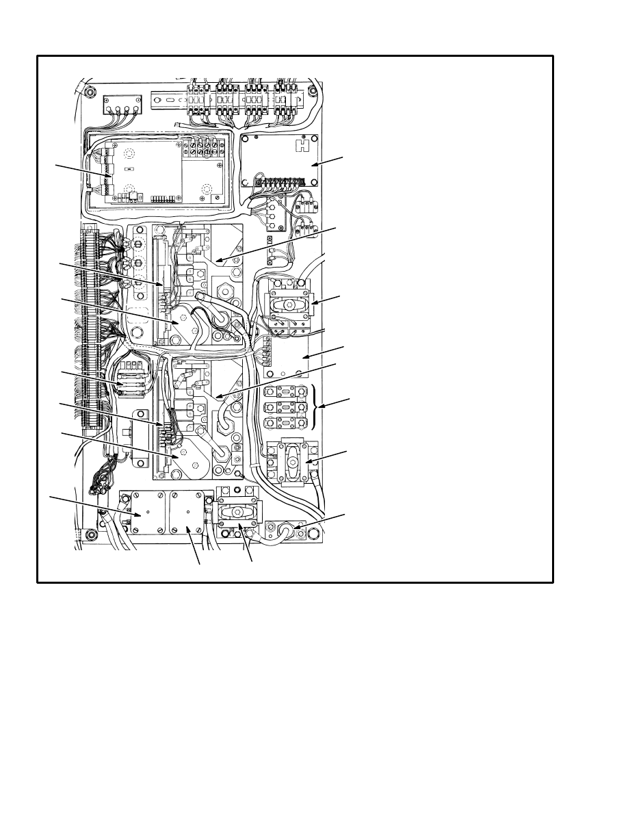
FIGURE 3. COMPONENT LOCATIONS, R30EH LIFT TRUCKS
1. ELECTRONIC CONTROL
MODULE
2. CONTROL CARD, HYDRAULIC
PUMP
3. CONTACTOR C1
4. FUSES, CONTROL CIRCUIT
5. CONTROL CARD, TRACTION
CIRCUIT
6. CONTACTOR, REVERSE
DIRECTION
7. CONTACTOR, FORWARD
DIRECTION
8. CONTACTOR, REGENERATIVE
BRAKING
9. DIODE D7
(REGENERATIVE BRAKING),
10. CONTACTOR, STEERING PUMP
11. FUSES, TRACTION CIRCUIT
HYDRAULIC PUMP. AND
STEERING
12. MOTOR CONTROL MODULE,
TRACTION
13. POWER DISCONNECT
MODULE
14. CONTACTOR, BATTERY
DISCONNECT
15. MOTOR CONTROL MODULE,
HYDRAULIC PUMP
16. AUTOMATIC SHUT–OFF
MODULE
1
2
3
4
5
6
3
7
8
9
10
11
12
13
14
15
16
5
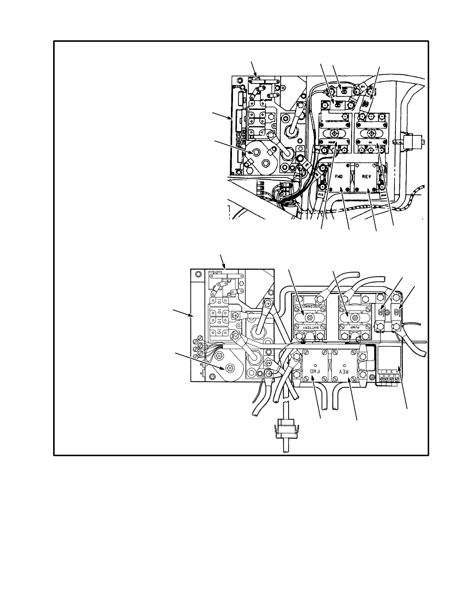
FIGURE 4. COMPONENT LOCATIONS, EV–100 CONTROLLER
12373
12372
1. MOTOR CONTROL MODULE
2. CONTROL CARD
3. CAPACITOR C1
4. CONTACTOR, FORWARD
DIRECTION
5. CONTACTOR, REVERSE
DIRECTION
6. CONTACTOR, HYDRAULIC PUMP
MOTOR
7. CONTACTOR, BATTERY
DISCONNECT
8. CONTACTOR, 1A
9. ELECTRONIC DRIVER
10. FUSE, TRACTION CIRCUIT
11. FUSE, HYDRAULIC PUMP
12. FUSE, AUXILIARY PUMP
N40–50EA, N40–45ER LIFT TRUCKS
R30E/EA/EF LIFT TRUCKS
1
1
2
2
3
3
4
4
5
5
6
7
6
8
9
10
11
10
11 12
6
12657
FIGURE 5. TYPICAL CONFIGURATION OF THE EV–100 MOTOR CONTROLLER
(TRACTION OR HYDRAULIC PUMP CONTROLLER GROUP)
1
2
3
1. CONTROL CARD
2. CAPACITOR C1
3. BASE PLATE
4. SCR 1
5. DIODE D3
6. MOTOR CURRENT SENSOR
7. DIODE D4
6
7
8
4
5
9
10
11
12
13
14
8. REACTOR (INDUCTOR L1 AND 1X)
9. SCR 2 AND SCR 5 (NOT SHOWN)
10. SUPPRESSOR MOUNT
11. SUPPRESSOR, SCR 5 AND SCR 2
12. SUPPRESSOR, SCR 5 AND SCR 2
13. SUPPRESSOR, D4
14. SUPPRESSOR, D3
FUSES
The fuses are found on or near the EV–100 controller.
The fuses for the different lift trucks are shown in
TABLE 1.
The power fuses for the traction circuit and for the hy-
draulic pump are found on the (+) bus bar. The control
fuses are in fuse holders on or near the controller. The
condition of the fuses can be normally be checked by
looking at them or checked with an ohmmeter.

7
TABLE 1. FUSES
LIFT TRUCKS
POWER FUSES
CONTROL CIRCUIT FUSES
Traction
Hyd.
pump
Steering
Control
Battery
Ind.
Hour
Meter
LED
Display
Accel.
Card
E20–30B/BS/BH
225A
175A
30A
15A
N/A
N/A
N/A
10A
E30–60B/BS
36–48 Volts
72–80 Volts
250A
175A
200A
150A
30A
10A
N/A
N/A
N/A
10A
E60–120B
36–48 Volts
72–80 Volts
200A (2)
175A
200A (2)
150A
30A
10A
N/A
N/A
N/A
10A
E/J1.25––3.00XL (E/J25–60XL)
500A
325A
40A
15A
15A
10A*
10A
N/A
E3.5–5.5XL (E70–120XL)
800A
325A (2)
40A (2)
15A
15A
10A*
10A
N/A
J25–35A, J25–35B
500A
325A
40A (2)
15A
N/A
N/A
N/A
10A
J40–60A, J50–60AS
36–48 Volts
72–80 Volts
250A
175A
200A
150A
30A
15A
N/A
N/A
N/A
N/A
N40–50EA And N40–45ER
300A
500A
60A
15A
N/A
N/A
N/A
N/A
R30E/EA/EF
300A
500A
35A
15A
N/A
N/A
N/A
N/A
R40EH
175A
400A
63A
15A (3)
N/A
N/A
N/A
N/A
*Later production lift trucks only. Earlier production lift trucks do not have a separate fuse.
N/A = Not Applicable
CONTROL CARD
The control card is a printed circuit board with elec-
tronic parts in a plastic case. The control card has two 6
pin plugs (PA and PB) that connect the signal wires be-
tween the parts of the controller and the control card. A
14 pin plug (PC) connects the control card to the func-
tions for SCR 1, SCR 2, and SCR 5. Two machine
screws at the bottom of the plastic case fasten the control
card to the mounting plate. The control card for each
function and the position of each control card is the same
in both configurations of the controller.
Different control cards are used in the electric lift trucks
made by Hyster Company. A replacement control card
must be the same part number as the control card that
was removed. Lift trucks that are equipped with the re-
generative braking function use a different control card
than lift trucks that only use a plugging function. These
two control cards for the traction circuit have a different
shape and must not be used as a replacement for the
other control card. The control card used in lift trucks
equipped with an SCR control for the hydraulic pump
can not be used for one of the control cards for the trac-
tion circuit. A bad control card must be replaced because
it cannot be repaired by service persons.
An R–1 control card used when a lift truck is equipped
with either field weakening or regenerative braking or
both functions. A T–1 control card is used when a lift
truck has only the plugging function.
The control card for the traction circuit has an ”Static
Return to OFF” (SRO) circuit. The key switch and seat
switch must be closed before the accelerator is moved to
operate the lift truck. A service person must understand
the SRO sequence when troubleshooting. The SRO is a
safety circuit that normally prevents the FORWARD or
REVERSE travel of the lift truck unless the operator is
in the correct position at the controls. If a service person
must operate the lift truck with a by–pass on the SRO
circuit, raise the drive wheels so that the lift truck can not
move and cause an accident.
The control card for the traction circuit has a ”Pulse
Monitor Trip” (PMT) circuit that checks for a malfunc-
tion of SCR 1. If SCR 1 does not operate with pulses, but
stays ”ON” continuously, the controller will open the di-
rection contactor and stop the lift truck.
8
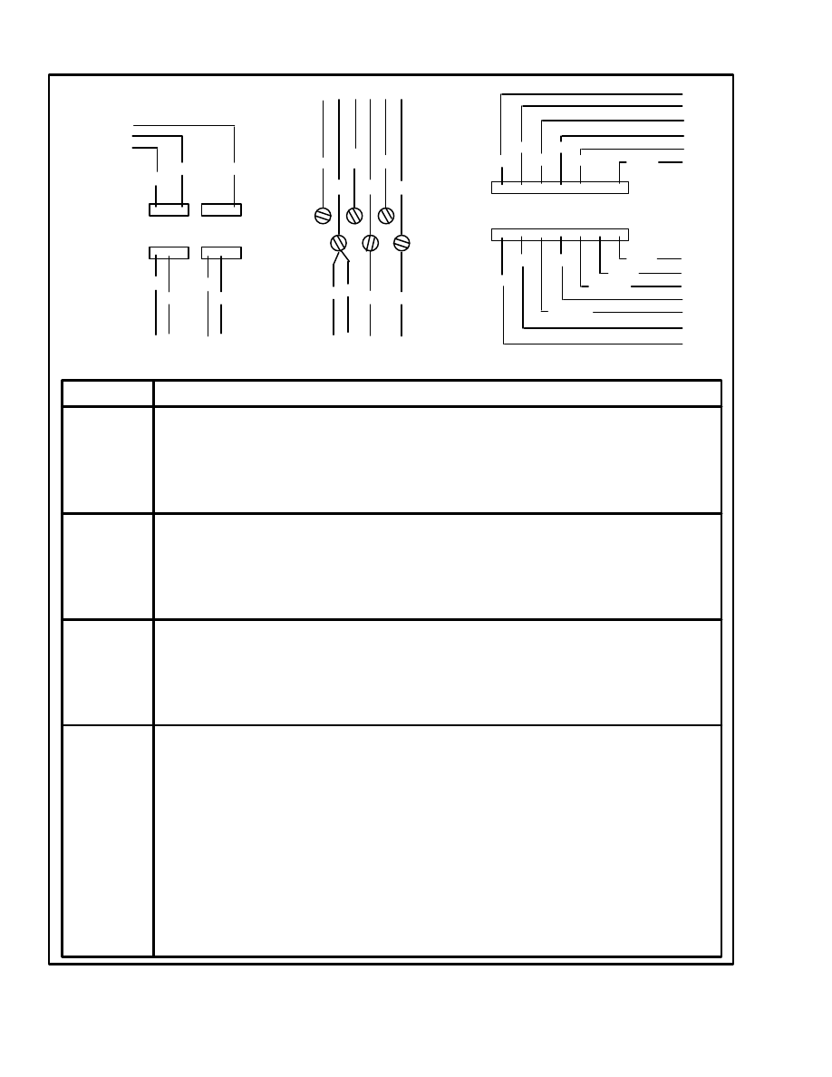
FIGURE 5. TERMINAL AND PIN ARRANGEMENTS FOR THE CONTROL CAR
(TRACTION CIRCUIT)
NO.
FUNCTION
PA1
PA2
PA3
PA4
PA5
PA6
PB1
PB2
PB3
PB4
PB5
PB6
TB1
TB2
TB3
TB4
TB5
TB6
PC1
PC2
PC3
PC4
PC5
PC6
PC7
PC8
PC9
PC10
PC11
PC12
PC13
PC14
Signal to energize the regenerative braking electronic driver (wire 32).
Not used.
Voltage check for regenerative braking function (wire 17).
Signal to the regenerative braking sensor (wire 22).
Signal to the regenerative braking sensor (wire 21).
Not used.
Not used.
Not used.
Signal to energize the field weakening electronic driver (wire 38).
Signal to energize the PMT electronic driver (wire 24).
Signal to energize the 1A electronic driver (wire 34).
Not used.
5 volt supply to accelerator potentiometer (wire 29).
Signal connection between START switch and control card (wire 57A).
Voltage input from timer circuit (wire 7).
Battery voltage supply from key switch (wire 10).
Voltage input from FORWARD direction switch (wire 6).
Voltage input from REVERSE direction switch (wire 8).
Signal wire from SCR 1 thermal protector (black wire).
Battery negative (brown wire).
Signal wire from current sensor (traction circuit) (yellow wire).
Signal wire from current sensor (traction circuit) (green wire).
Signal wire from SCR 1 thermal protector (gray wire).
Not used.
Battery positive voltage (white wire).
Signal wire to SCR 1 gate (blue/white wire).
Signal from SCR 1 cathode (blue wire).
Signal wire to SCR 2 gate (white/red wire).
Connection between filter for SCR 2 and control card (red wire).
Signal wire to SCR 5 gate ( white/violet wire).
Connection between filter for SCR 5 and control card (violet wire).
Sensor wire for voltage check across capacitor C1 (orange wire).
d d d
d d d
d d d
d d d
1 2 3
1 2 3
4 5 6
4 5 6
A
B
C
d d d
d d d
1
2
3
4
5
6
d d d
d d d
d
d
7
8 9 10 11 12
14
13
TB1
TB2
TB3
TB4
TB5
TB6
32
22
17
38
21
24
34
29
57
A
7
10
6
8
6
8
10 10
WHT
ORN
PUR
W/PUR
GRY
GRN
RED
YEL
BRN
W/RED
BLU
BLK
W/BLU
PLUG A
PLUG B
TERMINALS
PLUG C
FIGURE 6. TERMINAL AND WIRE ARRANGEMENTS FOR THE CONTROL CARD
(TRACTION CIRCUIT)
9
The Control Card Plugs
There are no connections in the signal wires between the
control card plugs and the components at the other end
of the wires. If a signal wire must be replaced, the opera-
tion to remove a pin connector from one of the plugs
must be done carefully. A special tool, part number
91065–1, is available from Amp Incorporated (manu-
facturer of electronic connectors) (Hyster Part No.
897408) to remove the pin connectors from the plugs.
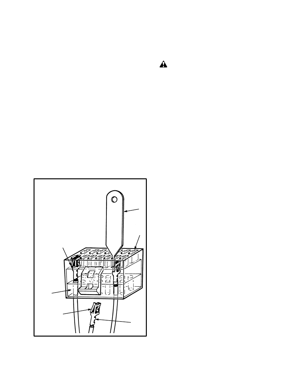
FIGURE 7. shows how the pin connectors are held in
the plug and how the tool releases the lock so that the pin
connector can be removed from the plug. If a pin con-
nector must be removed, the service person must work
carefully so that the pin connectors and the plug are not
damaged.
When a new pin connector is installed in the plug, make
sure it is not damaged and is locked into the correct posi-
tion in the plug. If the pin connection becomes loose
during operation of the lift truck, the fault can be not
regular and difficult to find and repair.
11559
1. PLUG
2. RUBBER SEAL
3. PIN CONNECTOR
(REMOVED FROM PLUG)
4. LOCK
5. PIN CONNECTOR
(INSTALLED IN PLUG)
6. TOOL (UNLOCKS PIN
CONNECTOR FOR
REMOVAL)
FIGURE 7. CONTROL CARD PLUG
1
6
5
2
4
3
P
A
R
T
NO. 897408
HOW TO CHECK AN SCR (See FIGURE 8.)
In the section TROUBLESHOOTING, for each electric
lift truck, there are instructions to check the SCRs. This
section describes the methods to check the SCRs.
WARNING
Make sure you disconnect the battery and separate
the connector before you disassemble any part of the
controller. Make sure you also discharge capacitor
C1.
NOTE: The following checks will indicate most SCRs
with a problem. The checks will not always indicate a
fault that does not occur regularly during operation. An
SCR with a type of fault that does not occur regularly
will normally indicate a resistance between the anode
and cathode of less than 50 000 ohms.
You will need a Cir/Kit or an ohmmeter to check the
SCRs. The SCRs can be checked without removing
them from the controller.
Six volts is needed for a gate signal to check the SCRs.
Use an ohmmeter and a six volt supply for a gate signal
or use a Cir/Kit meter to check the SCRs. The Cir/Kit
has a six volt supply for testing SCRs.
1. Disconnect the (+) or (–) connection to the SCR to
make a check for a short–circuit. Touch the probes of the
Cir/Kit or ohmmeter to the power connections on the
heat sinks (anode and cathode of SCR 1). Measure the
resistance. Change the probe connections to the reverse
direction and measure the resistance. Replace the SCR if
the resistance indicates less than 50 000 ohms in either
direction.
2. Measure the resistance between the gate connection
and the cathode. Change the probe connections to the re-
verse direction and measure the resistance again. Re-
place the SCR if the resistance indicates zero or infinity
on the R x 1 scale in either direction.
3. Connect the (+) probe of the ohmmeter to the anode
and the (–) probe to the cathode. Momentarily connect
six volts from the Cir/Kit [or a battery between the gate
(+) and the cathode (–)]. The resistance indication on the
Cir/Kit or the ohmmeter will decrease to less than 10
ohms on the R x 1 Scale. Replace the SCR if the resis-
tance does not decrease when a six volt gate signal is ap-
plied momentarily. Make sure you touch the gate con-
nection only momentarily with the six volt connection
10
or you will damage the SCR. Make sure the polarity of
your test circuit is correct.
The SCR 1 Assembly
The SCR 1 assembly cannot be disassembled. The SCR
1 assembly includes an SCR fastened between two
metal blocks used as heat sinks. The heat sinks are also
the power connections for the SCR. A plastic case holds
the complete assembly. There is a thin sheet of electrical
insulation between the SCR 1 assembly and the base
plate. The insulator permits heat to transfer from the
heat sinks to the base plate.
Thermal Protector
The SCR 1 has a thermal protector fastened to the cath-
ode heat sink. The thermal protector is a resistor that
changes resistance when the temperature changes.
When the temperature is greater than 85
°
C (185
°
F), the
thermal protector changes the signal
11566
FIGURE 8. HOW TO CHECK AN SCR 1, SCR 2,
OR SCR 5
1
2
3
4
5
6
5
4
1. SCR 1
2. THERMAL PROTECTOR
3. CATHODE (POWER CONNECTION)
4. ANODE (POWER CONNECTION)
5. GATE
6. SCR 2 OR SCR 5
3
voltage to the control card. The control card decreases
the percent of “ON” time to decrease the SCR 1 tem-
perature. The normal resistance for the thermal protec-
tor is 120 to 150 ohms at 18
°
C (65
°
F) when measured
between pins PC1 and PC5.
How To Replace The SCR 1 Assembly
1. Make notes of the positions of the suppressors and re-
move the suppressors from the mount over SCR 1. Dis-
connect the electric connections to the SCR 1 assembly.
2. Remove the thermal protector from the heat sink. Re-
move the two capscrews that connect the power cables
to the heat sinks (make a note of the cathode sensor
wire). Remove the two mounting screws that hold the
SCR 1 assembly to the base plate.
3. Check the insulator between the SCR 1 assembly and
the base plate. Replace the insulator if it is damaged. The
insulator is also a heat conductor. Use a very thin coat of
silicon grease (Part Number 1198757 or approved
equivalent) between the surfaces of the parts. Keep dirt
from the surfaces.
CAUTION
The insulator is very thin. Dirt between the surfaces
of SCR 1 and the base plate can damage the insulator
and cause a short–circuit.
NOTE: Silicon compound is used between the heat
sinks and the parts of the controller. The purpose of this
compound is to fill in the micrometer size spaces be-
tween the parts to give better heat flow. Always use a
very thin layer of compound between the parts. Too
much compound will be an insulator and cause both
electrical and heat faults. It is better to use no compound
instead of too much.
Part Number 1198757 is a silicon compound and is used
between heat sinks and the base plate. This silicon com-
pound must be used only as a very thin layer. DO NOT
USE this silicon compound on the threads of the diodes.
4. Install the new SCR 1 assembly. Make sure the heat
sinks make full contact with the insulator and base plate.
Check the resistance between both heat sinks and the
base plate with an ohmmeter. A correct installation will
indicate infinity on the ohmmeter.
5. Install the electrical connections to the SCR 1 assem-
bly. Install the thermal protector on the heat sink.
6. Install the mount and the suppressors over the SCR 1
assembly. Make sure the connections are made cor-
rectly.
11
11567
FIGURE 9. SCR “OFF” CIRCUIT COMPONENTS
1. CONTROL CARD
2. CAPACITOR C1
3. THERMAL SENSOR FOR SCR 1
4. SUPPRESSOR FOR D3
5. SUPPRESSOR FOR D4
6. SUPPRESSOR FOR SCR 5
7. SUPPRESSOR FOR SCR 2
8. INDUCTOR (L1 AND X1)
9. SCR 2
10. SCR 5
11. SCR 1
12. PLUG “C’ (SIGNAL WIRES TO
THE SCRs)
NOTE: SUPPRESSOR MOUNT
NOT SHOWN
1
2
3
4
5
6
7
8
9
10
11
12
THE ”OFF” CIRCUIT FOR SCR 1
WARNING
Make sure you disconnect the battery and separate
the connector before you disassemble any part of the
controller. Make sure you also discharge capacitor
C1.
The “OFF” circuit for SCR 1 has the following parts:
Inductor assembly
SCR 2
SCR 5
Suppressors for SCR 2 and SCR 5
Capacitor C1
The inductor and a capacitor assembly generates the re-
verse polarity voltage to change the SCR 1 to ”OFF” for
each pulse. SCR 2 and SCR 5 control the operation of
the “OFF” circuit. The suppressors protect the SCRs
from electrical noise.
Check The Inductor Assembly
The inductor assembly is in a plastic case that fastens to
the base plate. The connections for the inductor are un-
der the suppressor mount and are difficult to check with
an ohmmeter. A fault does not often occur in the induc-
tor assembly. Most faults that do occur at the inductor
assembly are caused by loose connections. The normal
repair of the inductor assembly is to replace it. This in-
ductor has two windings (L1 and 1X) joined by a com-
mon connection. A good inductor winding will indicate
approximately zero ohms on the R x 1 scale.
Check Suppressors For SCR 2 And SCR 5
The suppressors are one or more resistors and capacitors
in a small plastic block. See FIGURE 10. The suppres-
sors prevent damage to the SCRs from electrical noise.
Sometimes a suppressor will not indicate a problem ex-
cept when in an operating circuit and will cause a fault
that does not occur regularly during lift truck operation.
A bad suppressor can cause a fault similar to a bad SCR
2 or a bad SCR 5.
12
FIGURE 10. SUPPRESSORS
NOTE: Dotted lines
indicate internal con-
nections
3
4
5
6
1
2
1. SUPPRESSOR MOUNT
2. THERMAL SENSOR FOR SCR 1
3. SUPPRESSOR FOR D3
4. SUPPRESSOR FOR D4
5. SUPPRESSOR FOR SCR 5
6. SUPPRESSOR FOR SCR 2
The best method to check for a bad suppressor is to re-
place it and then check the operation of the lift truck.
NOTE: Some lift trucks are equipped with suppressors
that have different part numbers. These suppressors all
look the same, but the part numbers are different. Make
sure that the correct part number is used for each func-
tion. The following list shows the function and the part
number that appears on the suppressor. The Hyster Part
Number is in (parenthesis) following the function:
171B3940 G1 (SCR 2) (368914)
171B3940 G1 (SCR 5) (368914)
171B3940 G1 (D3) (368914)
171B3940 G3 (D4) (368916)
Later production lift trucks all use the same suppressor
[171B3940 G1 (368914)] for all functions. Replace-
ment suppressors for earlier production lift trucks can
use this universal part number.
Check SCR 2 And SCR 5
1. Disconnect either the (+) or (–) power connection.
(The power connections have a (+) and (–) mark in the
plastic case.) Touch the probes of the Cir/Kit or ohmme-
ter to the (+) and (–) power connections of the SCR.
Measure the resistance. Change the probe connections
to the reverse direction and measure the resistance. Re-
place the SCR if the resistance indicates less than 50 000
ohms in either direction.
FIGURE 11. SCR 2 AND SCR 5
1
2
3
1. ANODE
2. GATE
3. CATHODE
2. Measure the resistance between the gate connection
and the cathode. Change the probe connections to the re-
verse direction and measure the resistance again. Re-
place the SCR if the resistance indicates zero or infinity
on the R x 1 scale in either direction.
NOTE: Six volts is needed as a gate signal to check the
SCRs. Use an ohmmeter and a six volt supply for a gate
signal or use a Cir/Kit meter to check the SCRs. The Cir/
Kit has a six volt supply for testing SCRs.
3. Momentarily connect six volts from the Cir/Kit [or a
battery between the gate (+) and the cathode (–)]. The
resistance indication on the Cir/Kit or the ohmmeter will
decrease to less than 10 ohms on the R x 1 Scale. Replace
the SCR if the resistance does not decrease when a six
volt gate signal is applied momentarily. Make sure you
touch the gate wire momentarily with the six volt con-
nection or you will damage the SCR. Make sure the po-
larity of your test circuit is correct.
NOTE: If a Handyman Component Tester is used to
check SCR 2 and SCR 5, you must set the Tester to the
‘‘Hi’’ test gate. Only the ‘‘Hi’’ test gate will provide re-
liable measurements.
Replace The SCR 2 And SCR 5
NOTE: The plastic case for SCR 2 and SCR 5 is similar,
but the part numbers are different.
Disconnect the electrical connections to the SCR. Re-
move the two screws that hold the SCR.
Use a thin layer of silicon compound (Part Number
1198757 or approved equivalent) between the surfaces
of the heat sink and the replacement SCR. Install the
SCR. Connect the electrical connections.
13
Check Capacitor C1
Discharge C1 and disconnect the terminals before
checking C1 for a short–circuit. Measure the resistance
between the terminals. The ohmmeter will indicate a
low resistance and increase to more than 100 000 ohms.
A capacitor with a short–circuit must be replaced.
DIODES D3 AND D4
The heat sink assembly for the diodes D3 and D4 is also
the connection for the (–) power cable. The heat sink as-
sembly is connected to the base plate. A thin insulator
with a silicone surface separates the heat sink assembly
from the base plate.
NOTE: The optional SCR controller used for the hy-
draulic pump only has a diode D3.
Check The Diodes D3 and D4
You will need a Cir/Kit or an ohmmeter to check the di-
odes. Disconnect the cathode cables from the connec-
tors. The diodes can stay attached to the heat sinks to
make checks.
Touch the probes of the Cir/Kit or ohmmeter to the heat
sink and the cathode cable. Measure the resistance.
Change the probe connections to the reverse direction
and measure the resistance. A good diode will indicate 7
to 14 ohms on the R x 1 Scale in one direction and
greater than 50 000 ohms in the other direction.
11567
1
2
3
1. DIODE D3
2. DIODE D4
3. HEAT SINK
FIGURE 12. DIODES D3 AND D4
Replacement, Diodes D3 and D4
CAUTION
Do not use a hammer and punch to loosen or tighten
diodes.
Disconnect the cathode cable. Use a deep socket to re-
move the diodes. Put the wire through the top of the
socket and use a handle or wrench to turn the socket. Use
a thin layer of silicone grease (Part Number 304408) be-
tween the surfaces of the heat sink and replacement di-
ode. Tighten the diode to a torque of 3.4 N.m (30 lbf in).
NOTE: Diodes D3 and D4 have a suppressor connected
in parallel to the diode. Replace the suppressor and test
the operation if troubleshooting indicates that the sup-
pressor is bad.
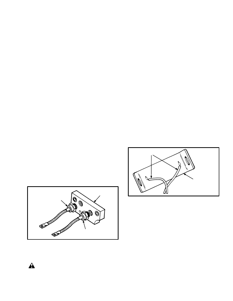
MOTOR CURRENT SENSOR
The motor current sensor is a short piece of the circuit
bus bar with two sensor wires connected to it. See
FIGURE 13. All of the traction motor current flows
through this power connector. The metal between the
connection points of the sensor wires has a small resis-
tance. This small resistance between the two sensor
wires sends a voltage signal to the control card. The
voltage signal increases as the motor current increases.
The control card compares the voltage with the “C/L”
current limit adjustment. The control card controls the
current flow so that the traction circuit is not damaged.
1. SENSOR WIRES
2. SENSOR SHUNT
FIGURE 13. MOTOR CURRENT SENSOR
2
1
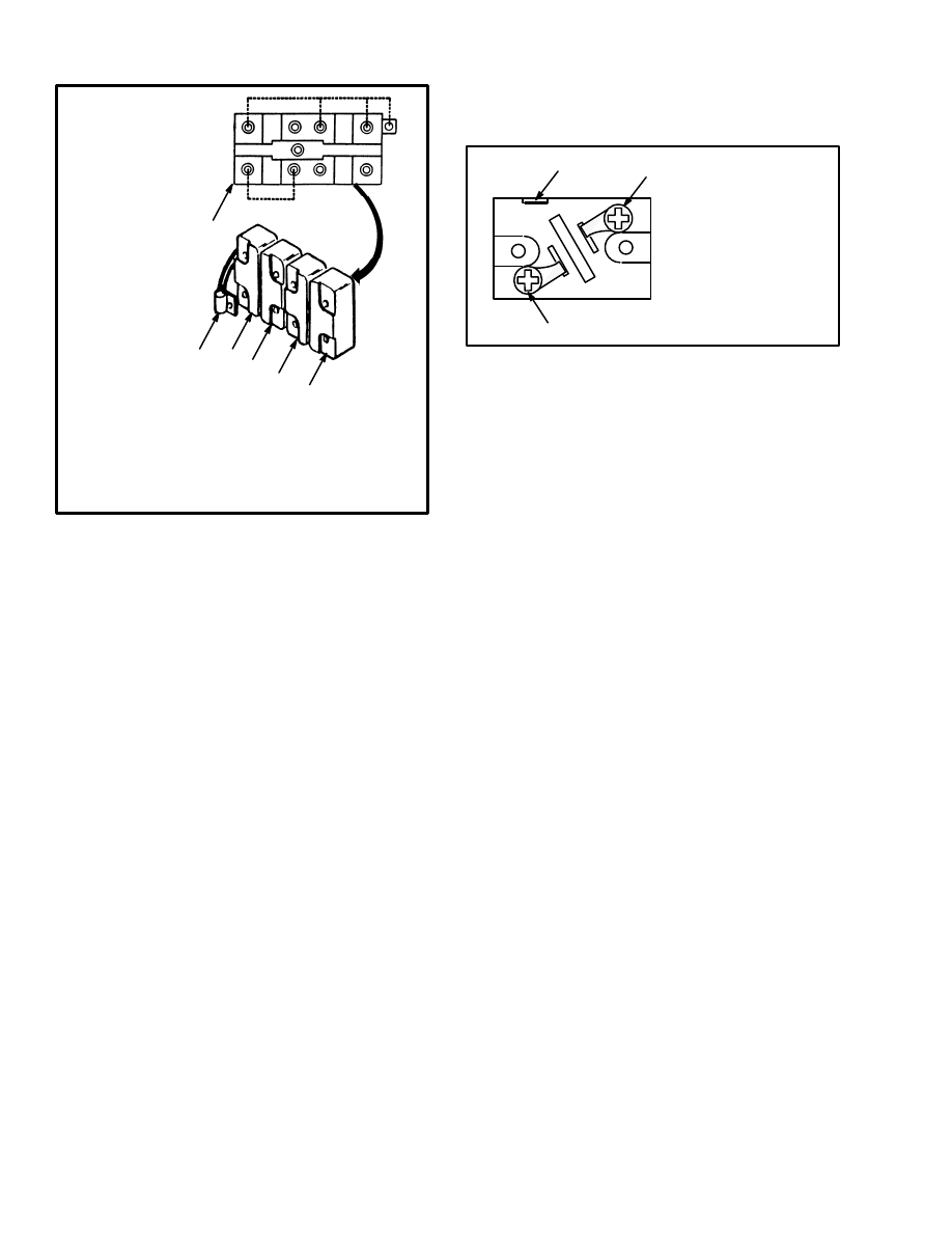
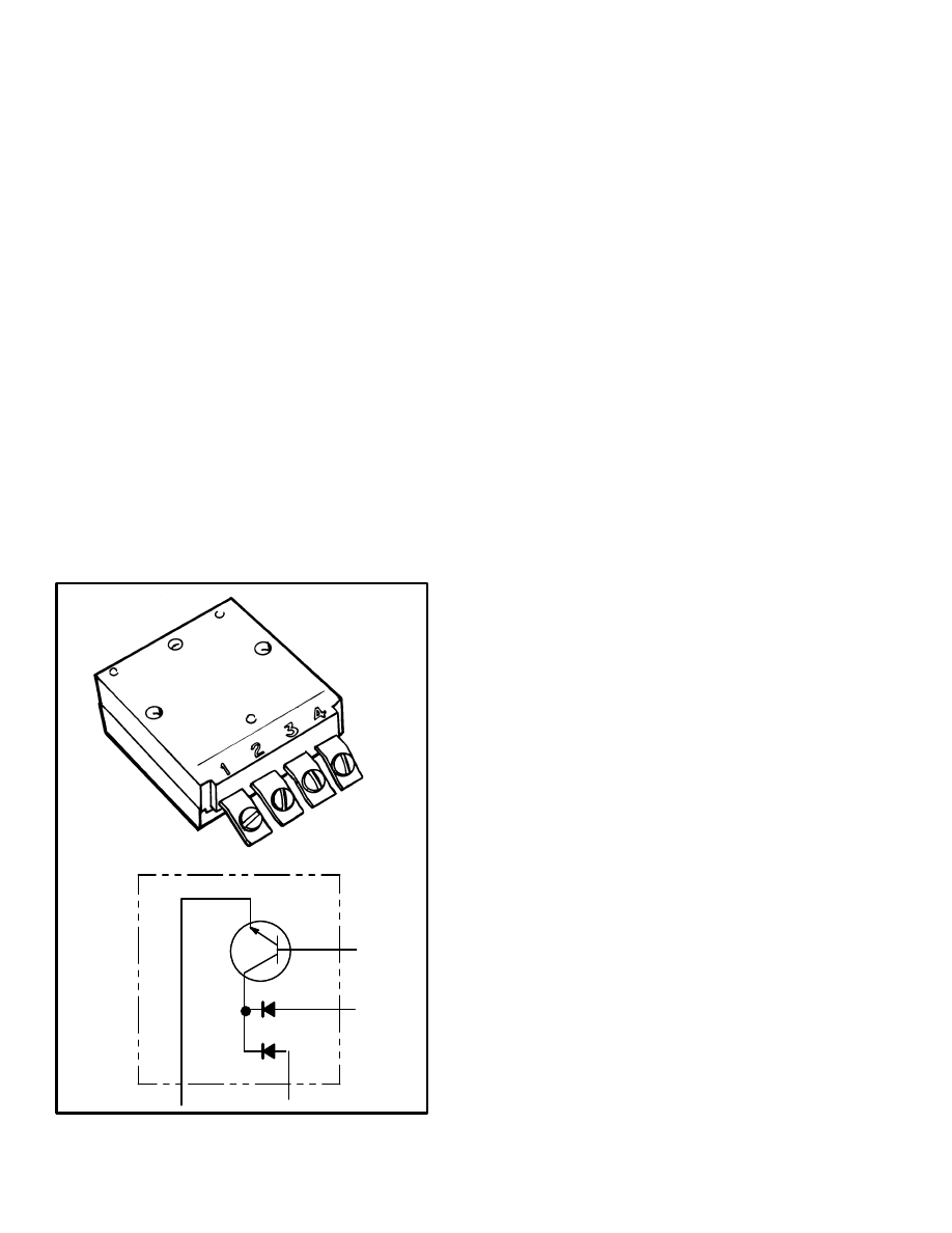
THE ELECTRONIC DRIVER MODULE
The electronic drivers are solid–state switches. The 2
volts and 5–10 milliampere signal from the control card
is too small to operate the contactor coils. The signal
voltage is used to control the electronic drivers which
have enough current capacity to operate the contactors.
The signal voltage is applied to the base of the transistor
terminal 1). The signal voltage causes current to flow
between terminals 3 and 2. (Terminal 4 is only used on
the PMT electronic driver for the ”FORWARD” contac-
tor).
NOTE: When a lift truck is equipped with regenerative
braking, a special electronic driver is used for the regen-
14
erative braking contactor. The regenerative braking
contactor has a special constant duty coil rated at 24
volts and must be used with the special electronic driver.
This special electronic driver looks like the other elec-
tronic drivers used in this controller. The special elec-
tronic driver has the following part number:
1C3645CPM1UDA9. This special electronic driver has
an internal circuit that reduces the battery voltage to an
average 17 volts applied to the coil of the regenerative
braking contactor. The coil of the regenerative braking
contactor will be damaged unless the special electronic
driver is used with it.
When the configuration of the controller was changed
during 1987, the special electronic driver for the regen-
erative braking function was removed. The coil on the
regenerative braking contactor was changed to a 36–48
volt rating. The coil is not rated for constant operation,
so a resistor is added in series with the coil on 48–volt lift
trucks to reduce the voltage. The same electronic driver
used for the other contactors is now used with the regen-
erative braking contactor.
5913
FIGURE 14. ELECTRONIC DRIVER MODULE
1
2
3
4
The resistor in series with the coil is installed in all
36–48 volt controllers. Two wires are connected to the
coil when the controller is received from the manufac-
turer. One wire is from the resistor and the second wire is
a by–pass around the resistor. If the controller is in-
stalled in a lift truck with a 48 volt battery, the by–pass
wire is disconnected. If the controller is installed in a lift
truck with a 36 volt battery, both wires stay connected
and the resistor does not function.
The electronic drivers used for the FORWARD, RE-
VERSE, and 1A contactors have the following part
numbers:
1C3645CPM1RDA2 (for 36–48 volt service)
The access to the electronic drivers on the bottom of the
stack is difficult. Remove the two mounting screws and
separate the drivers as necessary for access to the termi-
nals. Make sure you disconnect the battery when you
separate or connect the electronic drivers. Do not cause
a short–circuit.
The electronic driver modules are most easily checked
in the lift truck. Raise the drive wheels from the floor.
Connect the battery. Set the controls of the lift truck so
that the electronic driver you are checking will operate.
Check that there is an input signal on terminal 1 of
1.0–2.0 volts.
If there is 1.0–2.0 volts at terminal 1 of the electronic
driver, check for approximately battery voltage between
battery negative and terminal 3 or terminal 4. If there is
approximately battery voltage, the electronic driver is
damaged. A good electronic driver will indicate less
than 10 volts when measured between terminals 2 and 3
when the contactor is closed during operation.
CONTACTORS
The FORWARD and REVERSE contactor assemblies
control the direction of current flow through each trac-
tion motor. The contactor is a heavy–duty switch that
opens and closes the power circuit. The traction circuit
has a FORWARD and REVERSE contactor assembly.
Each contactor assembly has the following parts: two
sets of normally open (NO) contacts, two sets of nor-
mally closed (NC) contacts, and a coil. The coil is an
electromagnet that moves the NO contacts to the closed
position against spring pressure. The coil is in the con-
trol circuit. The contactor tips are in the traction circuit.
A suppressor is part of each coil. The contactors in your
lift truck can look different than the contactors shown in
15
FIGURE 15. or FIGURE 18., but the operation will be
similar.
NOTE: The suppressors are included with the coil in the
contactors manufactured before November 1987. The
suppressors are a separate component on the outside of
the coil of contactors manufactured after November
1987.
When a contactor coil is energized, the normally open
(NO) contacts close and the normally closed (NC) con-
tacts open. This action gives direction control to the
traction motor. The contacts normally have a long serv-
ice life because the current flow through the contacts is
stopped before the contacts open. The SCR 1 is ”OFF”
before the contactor coil is deenergized. The only condi-
tion where the contacts open during a large current flow
is PMT.
The other contactors used in the motor controller have
one set of NO contacts. These contactors are not the
same, but their operation is similar. A typical contactor
of this kind is shown in FIGURE 16. and FIGURE 19.
FIGURE 15. DIRECTION CONTACTOR
(AFTER 1987)
12180
1
1
1
3
2
4
4
5
6
1. POWER TERMINALS
2. NC CONTACTS
3. NO CONTACTS
4. COIL TERMINALS
5. MOUNT BRACKET
6. COIL
3
NOTE: The other contactors (1A, field weakening, and
regenerative braking) in the controllers manufactured
after November 1987 are like the design of the FOR-
WARD and REVERSE contactors except they are sin-
gle units and have only one set of NO contacts. When the
lift truck does not have an SCR controller for the hy-
draulic pump, the hydraulic pump contactor also has
one set of NO contacts.
FIGURE 16. TYPICAL CONTACTOR
ASSEMBLY (REGENERATIVE BRAKING
SHOWN)
1
5
1. POWER TERMINALS
2. CONTACTS
3. SUPPRESSOR
4. COIL TERMINALS
5. MOUNT BRACKET
6. COIL
1
4
2
2
3
6
CONTACTOR REPAIR
Removing A Contactor Assembly
Make an identification and disconnect the wires and ca-
bles from the contactor assembly. Remove the mounting
screws and remove the contactor assembly.
Contactor Contacts
The contactor contacts are made of special silver alloy.
The contacts will look black and rough from normal op-
eration. This condition does not cause problems with the
operation of the lift truck. Cleaning is not necessary. DO
NOT USE A FILE ON THE CONTACTS. DO NOT
LUBRICATE THE CONTACTS. Replace the contacts
when the silver alloy is worn away to the copper support
metal.
16
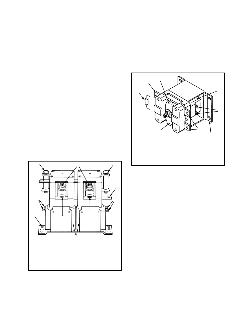
FIGURE 17.
FORWARD AND REVERSE CONTACTOR ASSEMBLY
(FOR CONTROLLERS MANUFACTURED AFTER NOVEMBER 1987)
12180
1. BASE–MAGNET
2. COIL
3. FRAME–MAGNET
4. BUS
5. BUS
6. SPACER
7. CLAMP–BUS
8. BUS
9. COVER
10. BUS
11. BUS
12. SPRING–RETURN
13. ARMATURE
14. BASE–BUS
15. CARRIER–MOVABLE TIP
16. BUSHING–PLUNGER
17. TIP–MOVABLE
18. SEAT–SPRING
19. TIP SPRING
20. INSULATION–UPPER BUS
21. NUT
22. WASHER
1
2
2
3
3
12
13
14
4
5
6
11
9
7
4
8
6
21
22
20
17
18
19
18
17
15,
16
15,
16
17
17
18
18
19
20
21
22
10
Coil
Check the coil with an ohmmeter. A suppressor diode
(and sometimes a resistor in series) is part of the coil.
The diode will cause the ohmmeter to indicate a differ-
ence in resistance in one direction. Reverse the probes of
the ohmmeter to the opposite terminals and measure the
resistance. Use the highest resistance indication. Re-
place the coil if it is damaged. Make sure the coil wires
are connected again to the correct terminals.
The coils in the contactors made after november 1987
have an external suppressor. The coil and the suppressor
can be checked separately with an ohmmeter.
17
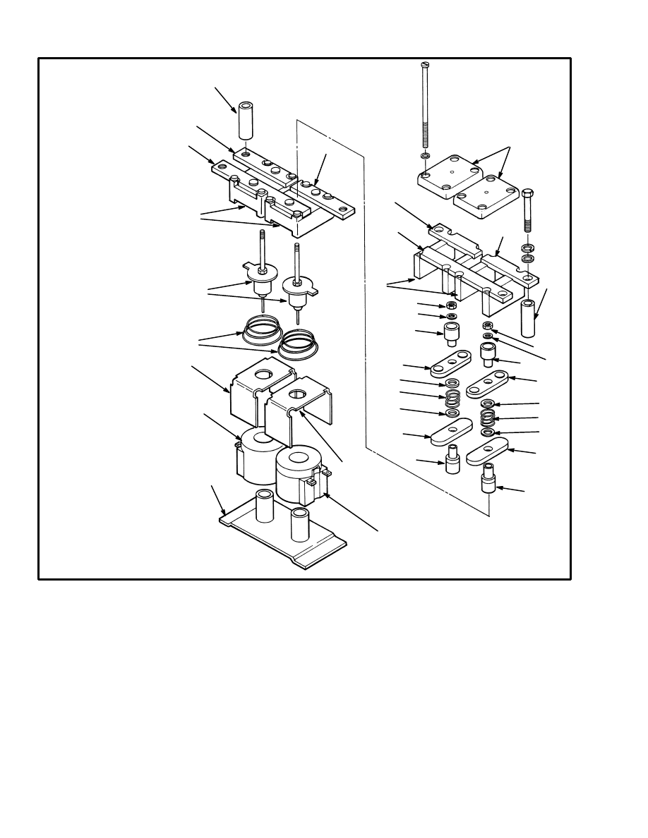
5497
NOTE: THE POWER CONNECTIONS FOR
THE FIXED CONTACTS CAN BE
DIFFERENT THAN SHOWN
FIGURE 18. FORWARD AND REVERSE CONTACTOR ASSEMBLY
(CONTROLLERS MANUFACTURED BEFORE NOVEMBER 1987)
1. BASE PLATE
2. COIL
3. SUPPORT FRAME
4. ARMATURE ASSEMBLY
5. FIXED CONTACTS (NO)
6. CENTER CONTACT CLAMP (2)
7. FIXED CONTACTS (NC)
8. UPPER CONTACT CLAMP
9. WASHER (4)
10. THROUGH BOLT (4)
11. SPRING
12. CORE ASSEMBLY
13. LOWER CONTACT SUPPORT
14. MOVING CONTACT CARRIER (2)
15. CONTACT SHIM
16. MOVING CONTACT (NO)
17. SPRING CUP (2)
18. MOVING SPRING CONTACT
19. MOVING CONTACT (NC)
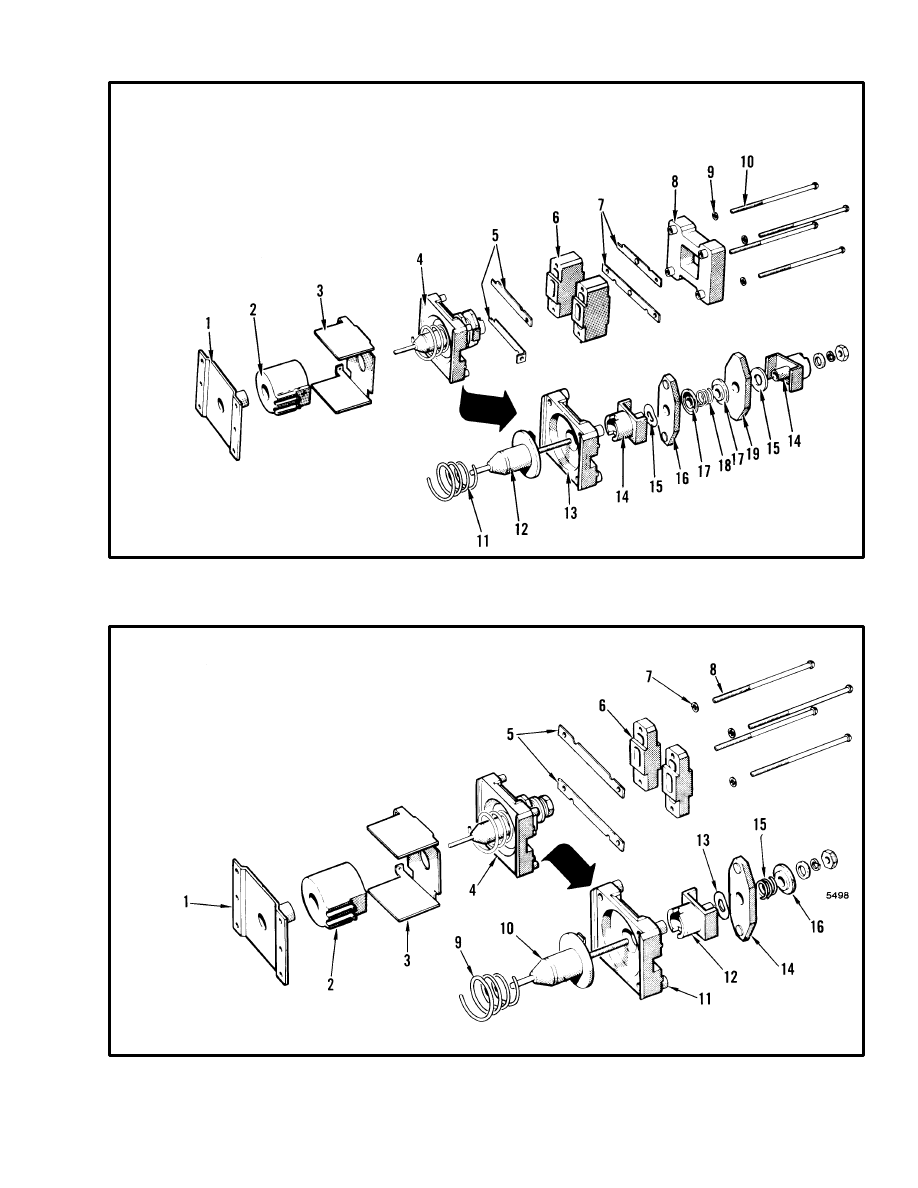
1. BASE PLATE
2. COIL
3. SUPPORT FRAME
4. ARMATURE ASSEMBLY
5. FIXED CONTACTS (NO)
6. UPPER CONTACT CLAMP (2)
7. WASHER (4)
8. THROUGH BOLT (4)
9. SPRING
10. CORE ASSEMBLY
11. LOWER CONTACT CLAMP
12. MOVING CONTACT CARRIER
13. CONTACT SHIM
14. MOVING CONTACT
15. MOVING CONTACT SPRING
16. SPRING CUP
5498
NOTE: THE POWER CONNECTIONS FOR
THE FIXED CONTACTS CAN BE
DIFFERENT THAN SHOWN
FIGURE 19. CONTACTOR ARRANGEMENT (HYDRAULIC PUMP, 1A, AND FW)
(CONTROLLERS MANUFACTURED BEFORE NOVEMBER 1987)

18
CONTROL CARD ADJUSTMENTS
This section has a description of the adjustments that are
on the control card for the electronic controller. Each ad-
justment is a potentiometer in the control card that turns
from a minimum control at (1) to a maximum control at
(9). The adjustments are normally set to the number
shown in the specification tables for each model series
of lift truck. See the section CAPACITIES AND
SPECIFICATIONS for your model of lift truck.
“CREEP”
This adjustment controls the minimum lift truck speed
when the direction contactors are closed. The adjust-
ment of the accelerator potentiometer must be correct
before the “CREEP” adjustment is made.
This adjustment can be set at a different number than
shown in the specifications. Some users want more ac-
celerator pedal movement before the direction contac-
tors close.
This adjustment can be set at a different number than
shown in the specifications. Some users want more ac-
celerator pedal movement before the direction contac-
tors close.
“C/A” (Controlled Acceleration)
This adjustment controls the maximum rate that the av-
erage voltage is increased by the controller to accelerate
the traction motor. How quickly the accelerator
(MONOTROL) pedal is pushed down does not control
the maximum rate of acceleration. A high rate of accel-
eration increases the wear of the brushes in the traction
motor. The acceleration is also selected to give a smooth
acceleration for better load handling. The acceleration
rate can be adjusted for the conditions of a user. Turn the
potentiometer counter–clockwise to decrease the accel-
eration rate.
“C/L”
Set the current limit to the number in the specifications.
Do not change the current limit without the approval of a
Hyster Company Service Engineer. If the current limit is
set higher than the specifications, parts of the traction
circuit can be damaged.
NOTE: A change was made in the control card during
August 1986 which requires a different setting of the
C/L limit than control cards of earlier manufacture.
Control cards made before August 1986 have a 099
mark on them. The part numbers for these control cards
are 325751, 325753, and 359787. These control cards
must be set to 9 for the current limit.
Control cards made after August 1986 have a 098 mark
on them and must be set to 5 for the current limit. The
actual current limit value for all control cards of these
part number series is approximately 235 amperes.
The controller and the traction circuit can be damaged if
the current flow is greater than the design specifications.
A current sensor is installed in the controller to check the
current flow. When the current becomes greater than the
setting on the control card, the current limit overrides
the other signals to the oscillator to decrease the pulse
width and frequency. Sometimes the current limit must
be checked in a lift truck. The following procedure is
used to check if the current limit is the same as the set-
ting on the control card. A damaged SCR 1 or SCR 5 can
be an indication that the current limit is set too high.
TABLE 2. through TABLE 4. shows the typical settings
for this controller. Also see the section CAPACITIES
AND SPECIFICATIONS for the model series of lift
trucks for current limits.
CAUTION
The battery shunt method of checking the current
limit can give errors because of variations in the trac-
tion motor and temperature. If the battery shunt
method must be used to check the current limit, use
this method carefully so that the controller and trac-
tion circuit are not damaged.
The ammeter shunt must be installed in the arma-
ture circuit and not the battery circuit if the follow-
ing current limits are checked:
“PLUG”
“C/L R.B.”
“DO R.B.”
1. Make sure the battery is charged and has a minimum
specific gravity of 1.260. Raise the drive wheels from
the surface.
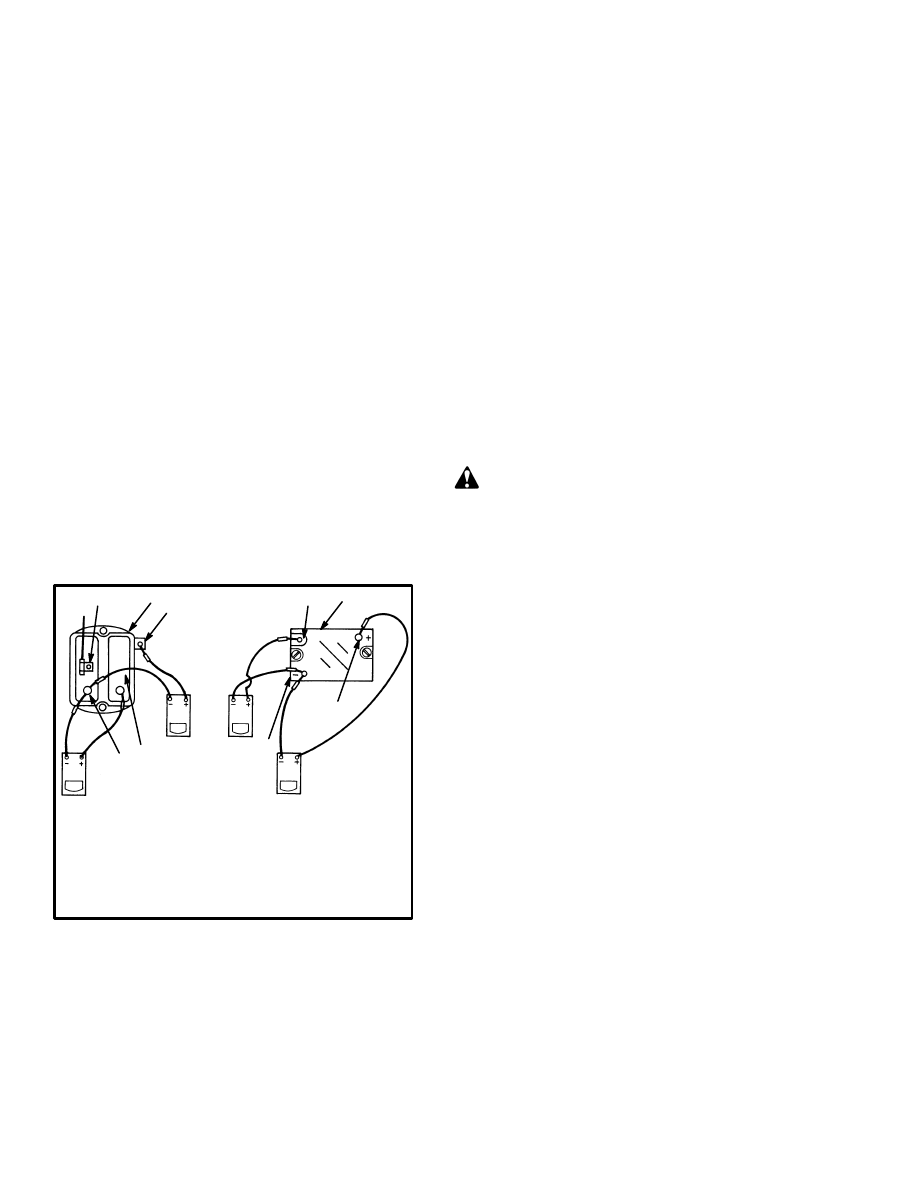
2. Connect a 0–500 ampere ammeter between the bat-
tery and the power circuit. Make sure that the polarity is
correct. (See FIGURE 20.) Make sure the ammeter ca-
bles are as short as possible. Install a jumper on the brake
switch so that it does not interrupt the operation of the
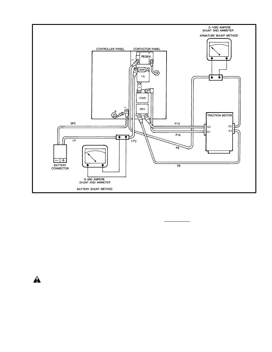
19
FIGURE 20. CONNECT THE DC AMMETER
controller. Disconnect the wire at terminal 1 of the 1A
electronic driver so that the 1A contactor can not close.
3. You must be on the operator’s seat. Turn the key
switch to the ”ON” position and apply the brake so that
the drive wheels can not rotate.
4. Look at the ammeter and push the accelerator
(MONOTROL) pedal for maximum forward speed.
Quickly check the ammeter indication and release the
accelerator pedal.
CAUTION
Do not cause the traction motor to stall for more than
10 seconds at a time. The traction motor will quickly
become hot. You want to set the current limit at oper-
ating temperatures or less. Give enough time be-
tween checks so that the traction motor can cool. Do
not hold the accelerator pedal pushed down while
adjusting the current limit.
5. Make an adjustment to the “C/L” potentiometer. Turn
the adjustment clockwise to increase the current limit.
Repeat Steps 4 and 5 until the correct current limits are
set.
The current draw from the battery for all 36–48 volt
lift trucks is approximately 235 amperes.
The current draw from the battery for all 72–80 volt
lift trucks must not be greater than 250 amperes.
6. Turn the key switch to the “OFF” position. Remove
the ammeter and remove the jumper from the brake
switch. Connect wire to terminal 1 of the 1A electronic
driver. Lower the drive wheels to the surface.
“1A TIME”
The “1A TIME adjustment permits the SCR control to
bring the traction motor up to speed before the 1A con-
tactor closes. This time delay prevents full battery cur-
rent being applied across the traction motor when it is
not rotating. This adjustment also permits smoother op-

20
eration of the lift truck. The control card begins “1A
TIME” when the accelerator voltage is decreased to less
than 0.5 volts.
“
1A TIME” is normally 1–3 seconds.
“PLUG”
The “PLUG” adjustment is normally set by the number
in the specifications. The plugging can be set to a user’s
conditions. The shorter the plugging distance, the faster
is the wear on the traction motor brushes.
“F.W.P.U. and “F.W.D.O.”
The field weakening (FW) system permits a higher trac-
tion motor speed than when only contactor 1A is closed.
(Field weakening is only used on 36–48 volt lift trucks.)
These two adjustments give limits to the current flow in
the traction motor when the field weakening contactor is
closed. These adjustments are made by using the amme-
ter arrangement shown in FIGURE 20.
1. Make sure the battery is charged and has a minimum
specific gravity of 1.260. Raise the drive wheels from
the surface.
2. Connect a 0–500 ampere ammeter between the bat-
tery and the power circuit. Make sure that the polarity is
correct. Make sure the ammeter cables are as short as
possible. Install a jumper on the brake switch so that it
does not interrupt the operation on the controller.
3. You must be on the operator’s seat. Turn the key
switch to the “ON” position and push the accelerator
pedal fully down while you look at the ammeter.
4. When the contactors 1A and FW have both closed, ap-
ply the brakes. Adjust the “F.W.D.O.” so that the contac-
tor FW opens at 400–450 amperes.
5. Push the accelerator (MONOTROL) pedal fully
down while you look at the ammeter. When the contac-
tors 1A and FW have both closed, apply the brakes so
that the contactor FW opens. Slowly release the brakes
until the contactor FW closes. Adjust the “F.W.P.U.” so
that the contactor FW closes at 150–180 amperes.
NOTE: Permit the brakes and traction motor to cool af-
ter each test. A hot traction motor will not give the cor-
rect adjustment.
6. Turn the key switch to the “OFF” position. Remove
the ammeter and remove the jumper from the brake
switch. Lower the drive wheels to the surface.
“REGEN C/L”
The “regenerative braking current limit” controls how
strongly the regenerative braking is applied during op-
eration. The higher the number setting, the shorter the
stopping distance. Set the control potentiometer to the
number indicated in the Specifications.
“REGEN D.O.”
The ”regenerative braking drop out” adjusts the voltage
level where the regenerative braking contactor closes
during regenerative braking. When the regenerative
braking contactor closes during regenerative braking,
the remainder of the lift truck speed is decreased by
plugging. The lift truck is normally moving slowly
when the plugging function begins operation. When the
plugging function is in operation, the voltage generated
by the traction motor is less than battery voltage. Set the
control potentiometer to the number indicated in the
Specifications.
VOLTAGE ADJUSTMENTS, SCR
CONTROL FOR HYDRAULIC PUMP
Connect a voltmeter so that the voltage can be measured
across the hydraulic motor. (Some service persons con-
nect the (+) probe of the voltmeter to the cable connec-
tion for D3 and the (–) probe to the P10 cable from the
pump motor.)
Move the TILT hand lever so that the pump motor oper-
ates at Speed 1 and measure the voltage. If the voltage is
not according to the specifications, adjust the voltage by
turning the SPD 1 potentiometer. Do not make voltage
measurements when the pump motor is operating
against the relief valve.
Move the LIFT hand lever so that the pump motor oper-
ates at speed 2 and measure the voltage. If the voltage is
not according to the specifications, adjust the voltage by
turning the SPD 2 potentiometer. Do not make voltage
measurements when the pump motor is operating
against the relief valve.
21
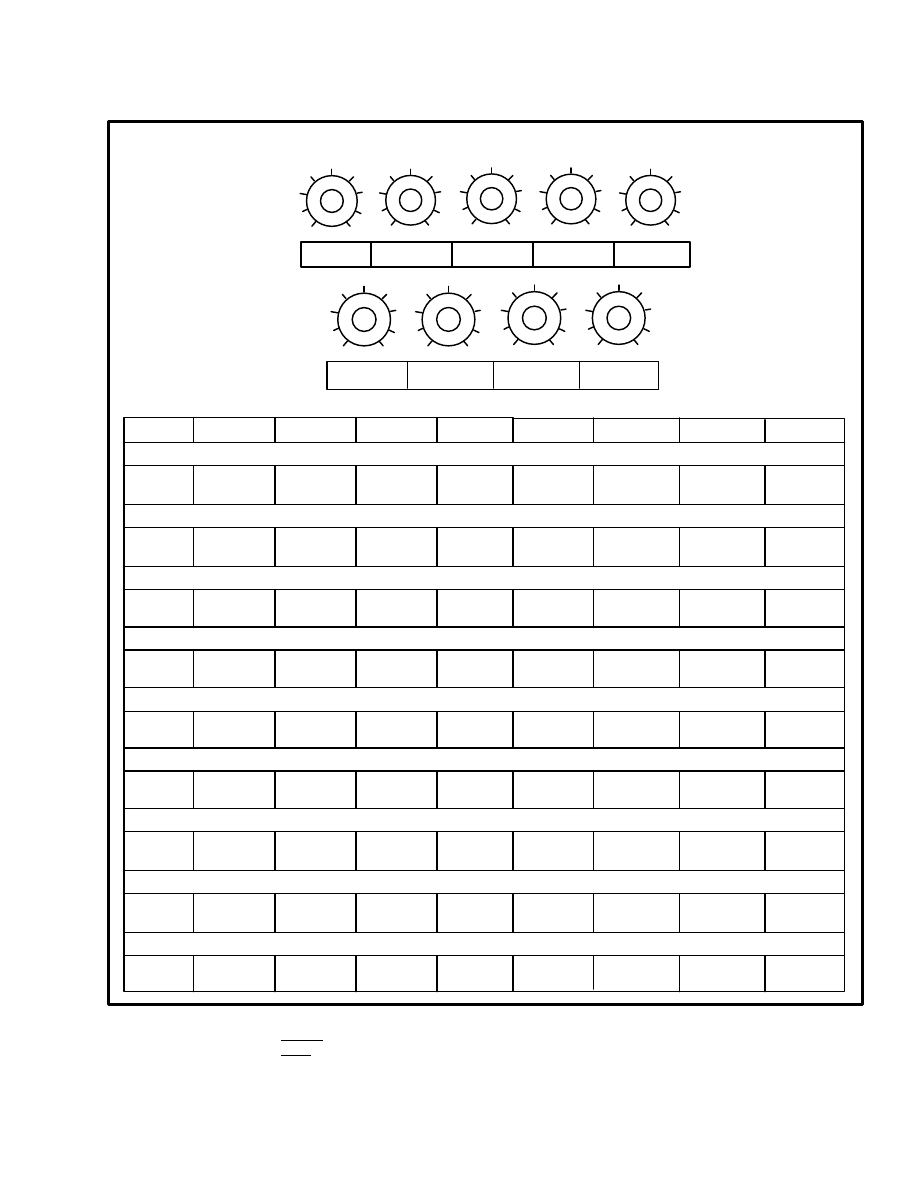
EV–100 MOTOR CONTROLLER ADJUSTMENTS
1
9
5
1
9
5
1
9
5
1
9
5
1
9
5
1
9
5
1
9
5
1
9
5
1
9
5
CREEP
C/A
C/L
1A TIME
PLUG
REGEN C/L REGEN D.O.
F.W.P.U.
F.W.D.O.
CREEP
C/A
C/L
1A TIME
PLUG
REGEN C/L REGEN D.O.
F.W.P.U.
F.W.D.O.
E1.25–1.75XL (E25–35XL) (36–48 volts with Regenerative Braking)
5
3
*
7
4
3.5
––
9
235 amp***
500 amp**
E1.25–1.75XL (E25–35XL) (36–48 volts with Plugging only)
5
4
*
4
4
––
235 amp***
500 amp**
––
––
––
6
7
*
4
1
3.5
7
8
9
235 amp***
500 amp**
450 amp***
6
4
*
4
2
––
––
––
235 amp***
500 amp**
6
4
4
4
2
3.5
––
––
9
250 amp***
475 amp**
E/J2.00–3.00XL (E/J40–60XL) (36–48 volts with Regenerative Braking)
E/J2.00–3.00XL (E/J40–60XL) (36–48 volts with Plugging only)
E/J2.00–3.00XL (E/J40–60XL) (72–80 volts with Regenerative Braking)
E/J2.00–3.00XL (E/J40–60XL) (72–80 volts with Plugging only)
1.4 sec
1.7 sec
185 amp***
350 amp**
8
5
4
4
5
––
––
––
250 amp***
1.8 sec
300 amp***
––
475 amp**
2.0 sec
1.0 sec
1.3 sec
350 amp**
J25–35B (24 volts)
––
––
6
2
*
5
5
––
––
––
235 amp***
500 amp**
––
J25–35B (36 volts)
4
2
*
5
5
––
––
––
235 amp***
500 amp**
––
* Control cards made before August 1986 and marked 099 must be set to a C/L of 9.
Control cards made after August 1986 and marked 098 must be set to a C/L of 5.
** Maximum current must be checked with the ammeter shunt in the armature circuit.
*** Maximum current must be checked with the ammeter shunt in the battery circuit.
TABLE 2. CONTROL CARD ADJUSTMENTS FOR THE TRACTION MOTOR CIRCUIT
(SitDrive
LIFT TRUCKS)
7
7
8
4
1
6
––
––
245 amp***
4
475 amp**
1.0 sec
0.55 sec
430 amp***
E3.50–4.00XL (E70–80XL) Not available on E4.50–5.50XL (E100–120XL) models
0.7 sec
1.3 sec
22
1
9
5
1
9
5
1
9
5
1
9
5
1
9
5
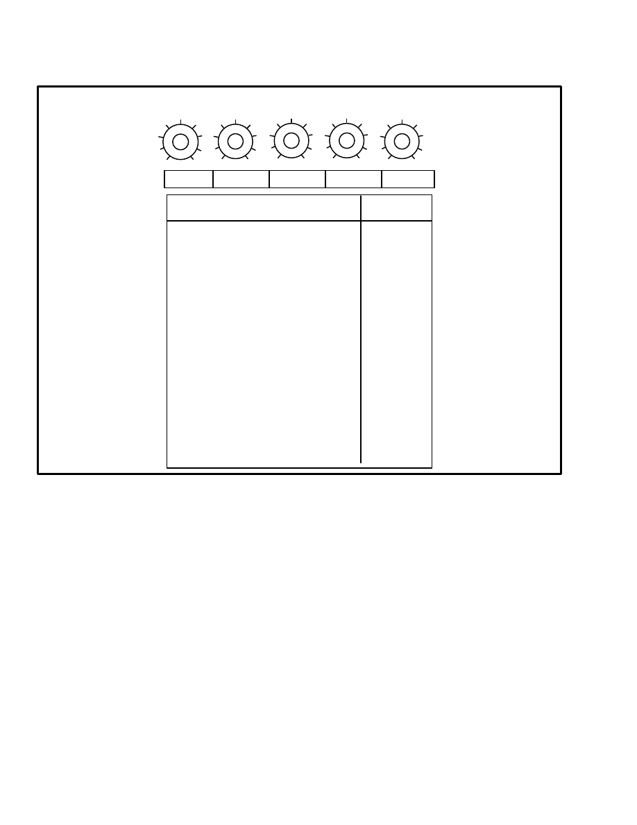
1A TIME
SPD 1
SPD 2
SPD 3
NOT USED
EV–100 MOTOR CONTROLLER ADJUSTMENTS
VOLTS
E1.25–1.75XL (E25–35XL) 36–48 volts
(open center)
SPEED 1 (Tilt)
SPEED 2 (Lift)
SPEED 3
C/A (300 milliseconds)
17
24
not used
E/J2.00–3.00XL (E/J40–60XL) 36–48 volts
SPEED 1 (Tilt)
SPEED 2 (Lift)
SPEED 3
3.5 (17 v)
3.5 (24 v)
not used
set to 6 on adj.
1A TIME
not used
C/A (300 milliseconds) set to 6 on adj.
1A TIME
not used
E/J2.00–3.00XL (E/J40–60XL) 72–80 volts
SPEED 1 (Tilt)
SPEED 2 (Lift)
SPEED 3
3 (40 v)
4 (50 v)
not used
C/A (300 milliseconds) set to 6 on adj.
1A TIME
not used
E3.50–5.50XL (E70–120XL) 36–48 volts
TABLE 3. CONTROL CARD ADJUSTMENTS FOR THE PUMP MOTOR CIRCUIT
(SitDrive
LIFT TRUCKS)
SPEED 1
SPEED 2 (Tilt)
SPEED 3 (Lift)
C/A (300 milliseconds)
1A TIME
1 (0 v)
4.5 (24 v)
9 Full On)
set to 6 on adj.
not used
LIFT TRUCK MODEL AND ADJUSTMENTS
23
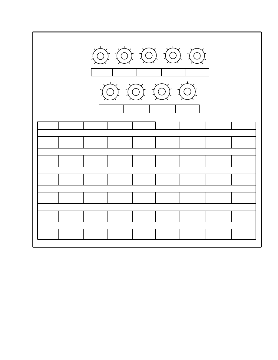
EV–100 MOTOR CONTROLLER ADJUSTMENTS
1
9
5
1
9
5
1
9
5
1
9
5
1
9
5
1
9
5
1
9
5
1
9
5
1
9
5
CREEP
C/A
C/L
1A TIME
PLUG
REGEN C/L REGEN D.O.
F.W.P.U.
F.W.D.O.
CREEP
C/A
C/L
1A TIME
PLUG
REGEN C/L REGEN D.O.
F.W.P.U.
F.W.D.O.
R30E, R30EA, R30EF (24 volts)
7.5
1.5
9
5
N/A
––
––
––
300 amp
440 amp
7
2
9
5
N/A
––
590 amp
––
––
––
7
5
7
1
3
4
––
––
––
640 amp
2
1
6
N/A
5
N/A
N/A
5
N40–50EA, N40–45ER (24 volts)
R40EH (Traction Circuit)
2.6 sec
1.4 sec
1A TIME
C/A
SPD–3
SPD–1
SPD–2
––
––
––
––
4*
4*
––
––
* Number settings of approximately 4 are not accurate. Set potentiometer for motor voltage of 33 volts.
1.3 sec
TABLE 4. CONTROL CARD ADJUSTMENTS FOR “N” AND “R” SERIES LIFT TRUCKS
2.3 sec
R30E, R30EA, R30EF (36 volts)
2.2 sec
288 amp
2
2.2 sec
9
300 amp
5
440 amp
––
––
––
––
N40–50EA, N40–45ER (36 volts)
9
288 amp
2
2.2 sec
R40EH (Hydraulic PumpController)
N/A
7
N/A
Document Outline
- EV-100 MOTOR CONTROLLER REPAIRS AND ADJUSTMENTS
Wyszukiwarka
Podobne podstrony:
897415 2200SRM0464 (01 1994) UK EN
897435 2200SRM0473 (03 1994) UK EN
897856 2200SRM0612 (01 1996) UK EN
897495 2200SRM0514 (01 2004) UK EN
1564268 2200SRM1106 (01 2004) UK EN
1595265 2200SRM1204 (01 2005) UK EN
1556871 2200SRM1105 (01 2004) UK EN
897844 2200SRM0603 (01 1996) UK EN
897844 2200SRM0603 (01 1996) UK EN
1564283 1900SRM1107 (01 2004) UK EN
1452929 2200SRM0679 (11 2003) UK EN
więcej podobnych podstron