ELECTRICAL
SYSTEM/LIGHTS
H36.00-48.00E (H800-1050E) [D117]
PART NO. 1452929
2200 SRM 679

SAFETY PRECAUTIONS
MAINTENANCE AND REPAIR
• When lifting parts or assemblies, make sure all slings, chains, or cables are correctly
fastened, and that the load being lifted is balanced. Make sure the crane, cables, and
chains have the capacity to support the weight of the load.
• Do not lift heavy parts by hand, use a lifting mechanism.
• Wear safety glasses.
• DISCONNECT THE BATTERY CONNECTOR before doing any maintenance or repair
on electric lift trucks.
• Disconnect the battery ground cable on internal combustion lift trucks.
• Always use correct blocks to prevent the unit from rolling or falling. See HOW TO PUT
THE LIFT TRUCK ON BLOCKS in the Operating Manual or the Periodic Mainte-
nance section.
• Keep the unit clean and the working area clean and orderly.
• Use the correct tools for the job.
• Keep the tools clean and in good condition.
• Always use HYSTER APPROVED parts when making repairs. Replacement parts
must meet or exceed the specifications of the original equipment manufacturer.
• Make sure all nuts, bolts, snap rings, and other fastening devices are removed before
using force to remove parts.
• Always fasten a DO NOT OPERATE tag to the controls of the unit when making repairs,
or if the unit needs repairs.
• Be sure to follow the WARNING and CAUTION notes in the instructions.
• Gasoline, Liquid Petroleum Gas (LPG), Compressed Natural Gas (CNG), and Diesel fuel
are flammable. Be sure to follow the necessary safety precautions when handling these
fuels and when working on these fuel systems.
• Batteries generate flammable gas when they are being charged. Keep fire and sparks
away from the area. Make sure the area is well ventilated.
NOTE:
The following symbols and words indicate safety information in this
manual:
WARNING
Indicates a condition that can cause immediate death or injury!
CAUTION
Indicates a condition that can cause property damage!
Electrical System/Lights
Table of Contents
TABLE OF CONTENTS
General ...............................................................................................................................................................
Alternator ...........................................................................................................................................................
Description .....................................................................................................................................................
Remove and Disassemble ..............................................................................................................................
Clean ..............................................................................................................................................................
Inspect, Test, and Repair...............................................................................................................................
Rotor...........................................................................................................................................................
Rectifiers and Diode Set............................................................................................................................
To Test Rectifier With Ohmmeter: .......................................................................................................
To Test Rectifier With Test Lamp:........................................................................................................
To Test Diode Set:..................................................................................................................................
Drive End Frame.......................................................................................................................................
Brush End Frame......................................................................................................................................
Brushes and Brush Holder Assembly ......................................................................................................
Stator .........................................................................................................................................................
Assemble and Install .....................................................................................................................................
Meters, Senders, and Switches .........................................................................................................................
General ...........................................................................................................................................................
Troubleshooting..................................................................................................................................................
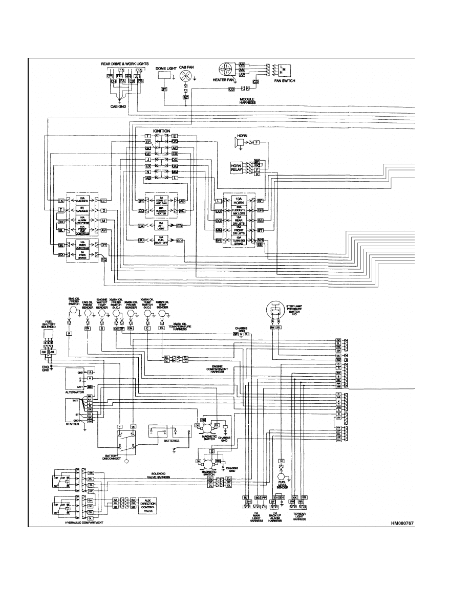
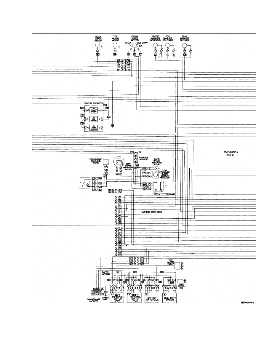
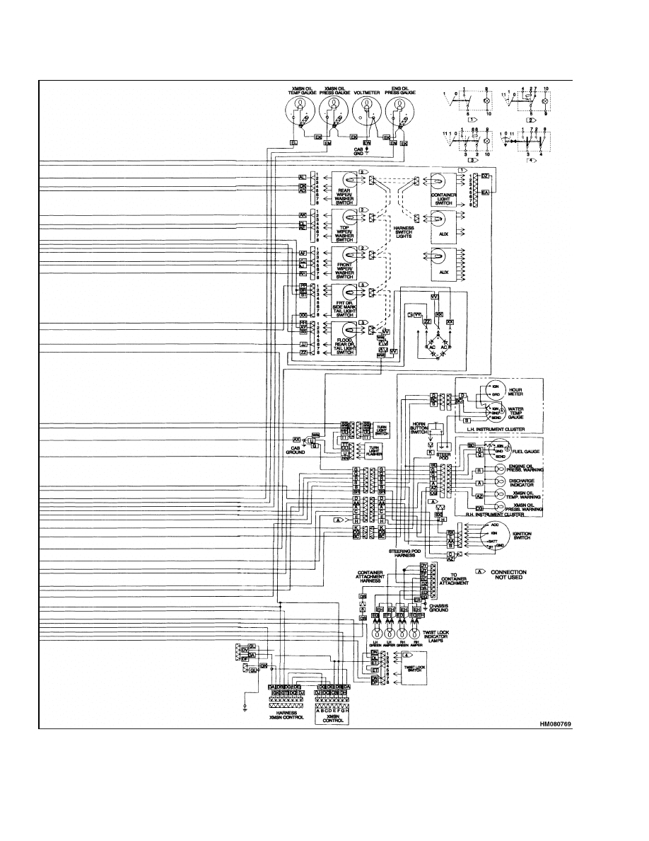
Diagrams, Schematics, or Arrangements .........................................................................................................
Figure 3. Electrical System Schematic ....................................................................................................
This section is for the following models:
H36.00-48.00E (H800-1050E) [D117]
©2003 HYSTER COMPANY
i

"THE
QUALITY
KEEPERS"
HYSTER
APPROVED
PARTS

2200 SRM 679
Alternator
General
WARNING
Always move the battery disconnect lever to
the "disconnected" position before making re-
pairs.
The diodes and resistors in the electrical sys-
tem can be damaged if the following cautions
are not followed:
• Do not disconnect the battery when the en-
gine is running. The voltage surge can dam-
age the diodes and resistors in the electrical
system.
• Do not disconnect an electric wire before the
engine is stopped and the switches are "OFF".
• Do not cause a short circuit by connection
of the electric wires to the wrong terminals.
Make sure a correct identification is made of
the wire before it is connected.
• Make sure a battery is the correct voltage and
polarity before it is connected.
• Do not check for current flow by making a
spark because the electronic components can
be damaged.
• These lift trucks have a 24 volt electrical sys-
tem (two 12-volt batteries in series). Be care-
ful when working on the electrical system.
CAUTION
When using an arc welder, always disconnect
the ground lead from the lift truck battery to
prevent alternator or battery damage. Attach
the welding ground clamp as close to the weld
area as possible to prevent welding current
from damaging the bearings.
This section has a description of the electrical sys-
tem and the repair procedures for the alternator with
an internal regulator. Contact your dealer for Cum-
mins engines for starter repair.
The replacement
procedures for meters and gauges are in the section
Instrument Panel Indicators and Senders 2200
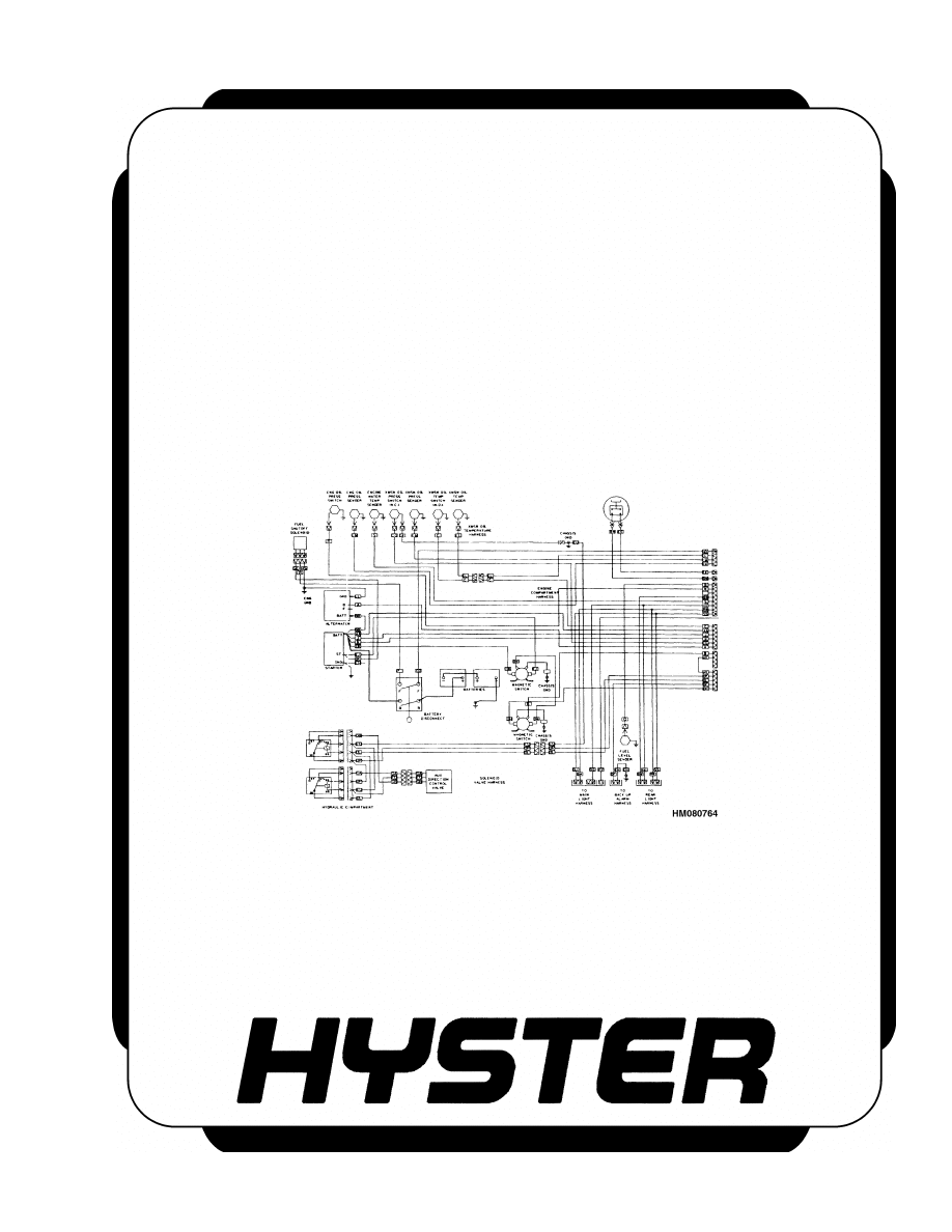
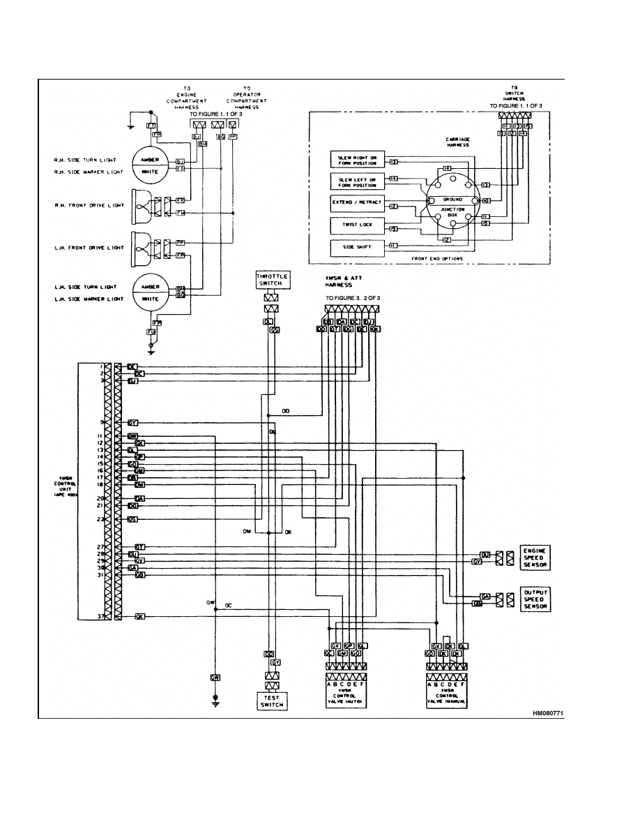
SRM 143. The electrical schematic diagram for the
lift truck is shown in Figure 3.
Alternator
DESCRIPTION
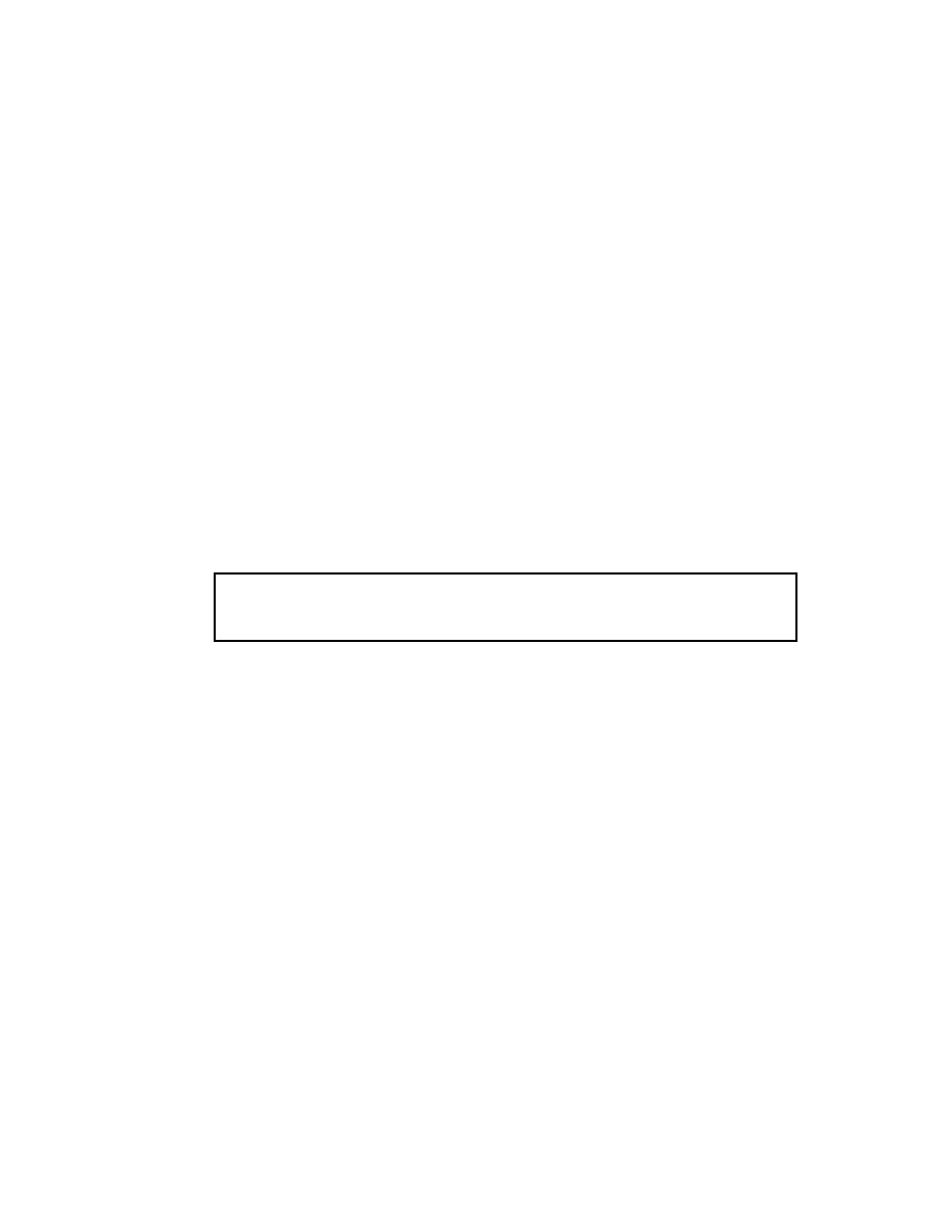
The Delco Remy model 22-SI alternator generates
a 24-volt alternating current when the engine is
running. See Figure 1. The alternating current is
changed to a 50-ampere direct current by six silicon
diodes contained in a rectifier assembly (rectifier
bridge).
The diode set continues the process of
changing the alternating current to direct current
(DC). The rectifier bridge, diode set, and regulator
are all mounted in the end frame for the slip rings.
Output from the alternator is controlled by the regu-
lator. The regulator controls the alternator output
by controlling the voltage of the field. Voltage for
the regulator is supplied as part of the output volt-
age from the alternator.
The alternator has these main parts:
• Stator
• Rotor
• Two end frames
• Solid-state voltage regulator
The direct current, from the diodes, flows to the out-
put or battery (BAT, B+) terminal. The voltage is con-
trolled by the amount of current flowing through the
field winding in the alternator and the rpm of the ro-
tor. The voltage regulator inside the frame contains
a transistor, diodes, and capacitors. The voltage reg-
ulator must be replaced, if faulty.
The voltage regulator is installed in the end of the
alternator with the slip rings. The voltage regulator
controls the current at the output or BAT B+ termi-
nal. The voltage is set by controlling the current in
the field winding of the alternator. The voltage is set
by the manufacturer and is not adjustable. When the
key switch is turned to the IGN position, the voltage
regulator is energized. A positive current flows to the
field terminal on the alternator. The battery sends
a positive current to the regulator terminal and the
battery (BAT B+) terminal.
1
Alternator
2200 SRM 679
1.
REGULATOR
2.
BATTERY (B+)
TERMINAL
3.
F
4.
F+
5.
DIODE SET
6.
INDICATOR LIGHT
TERMINAL
7.
ROTOR FIELD
COIL
8.
RELAY TERMINAL
9.
BRIDGE DIODE
RECTIFIER (6)
10. GROUND (B )
TERMINAL
11. STATOR
Figure 1. Alternator Diagram
The I or indicator light terminal sends a signal to the
indicator light on the instrument panel to indicate
that the battery is discharging and the alternator is
on to charge the battery. The R or relay terminal is
not used. The B
or ground terminal is connected to
chassis ground.
REMOVE AND DISASSEMBLE
WARNING
Always move the battery disconnect lever to
the "disconnected" position before doing any
disassembly or repair to the parts of the elec-
trical system.
CAUTION
Before disassembling the alternator, make
marks on all housings to make sure of the
correct parts alignment during assembly.
1.
Disconnect the wires at the alternator. Use a
socket to move the arm of the belt tensioner and
remove the drive belt from the pulley. Remove
the capscrews that fasten the alternator to the
bracket.
2.
Remove the nut, pulley, and fan from the shaft.
See Figure 2. Make alignment marks on the sta-
tor and frames. Then remove the bolts that fas-
ten the frames and stator together.
3.
Remove the drive end frame and rotor from the
stator. If the bearing will be replaced, remove the
rotor from the drive end frame. Use a gear puller
or press and remove the bearing from the drive
end frame.
4.
Remove the nuts and screws that connect the sta-
tor leads, diode set, regulator, capacitor, termi-
nals, and rectifier assembly. Make a note of the
location, disassembly sequence and the correct
connections of the nuts, insulators, screws, and
components for correct assembly.
5.
Use compressed air to remove dirt from the al-
ternator. Clean the brushes and slip rings with
a clean dry cloth.
CLEAN
CAUTION
Never use solvent on the stator or rotor. Use
a dry cloth to clean these parts. Use solvent
on a cloth to clean other external parts of the
alternator. Dry the parts with compressed air.
Read previous caution before cleaning any parts.
INSPECT, TEST, AND REPAIR
Clean the terminals on the battery. Inspect the insu-
lation on the wires. See Figure 2. Make sure all the
fasteners and connections are clean and tight.
Rotor
1.
Check for damage to the threads and bearing sur-
faces. See Figure 2.
2.
Test the insulation between the slip rings, wind-
ings, and rotor body. Use a 110-volt, 15-watt test
lamp.
3.
Use an ohmmeter and check the resistance of the
rotor windings. The resistance should be less
than 20 ohm.
2
2200 SRM 679
Alternator
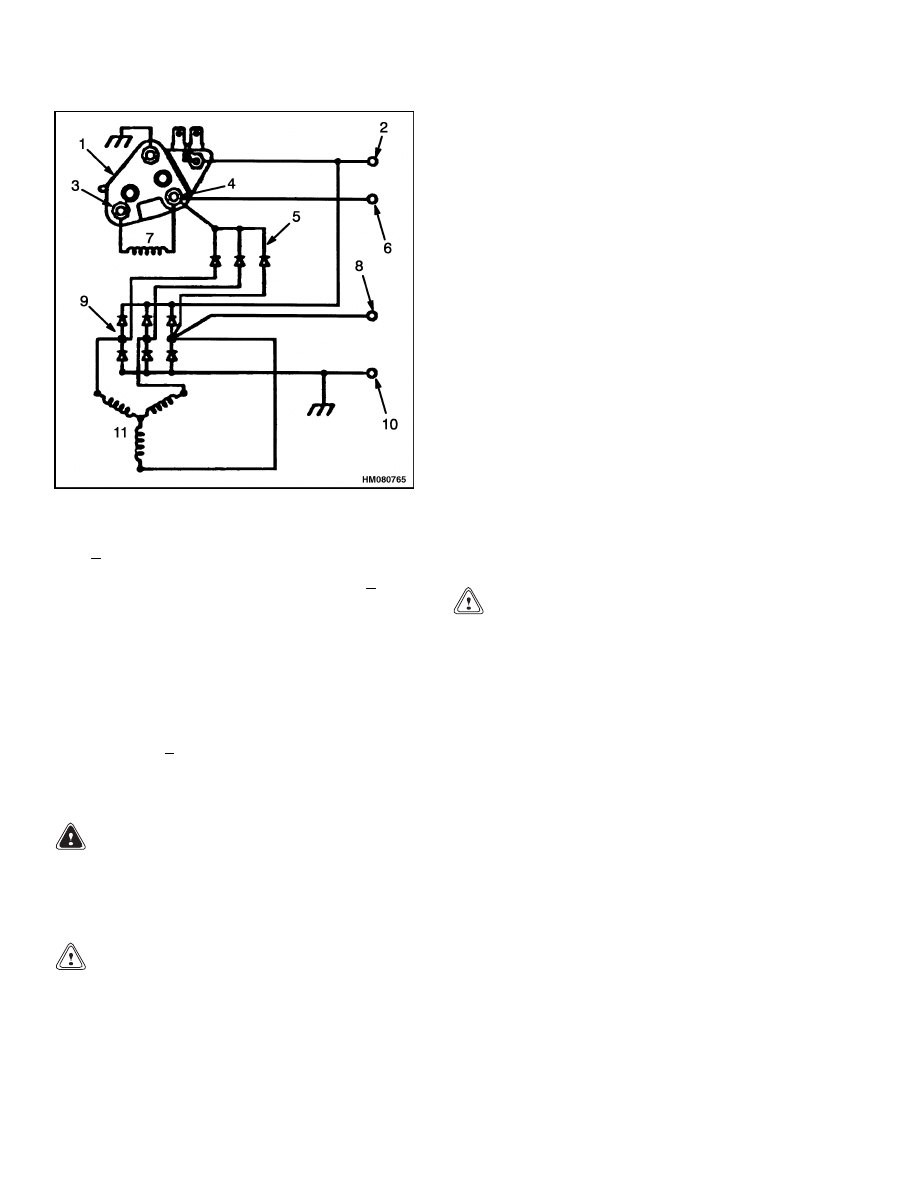
1.
STATOR
2.
BRUSH
3.
BRUSH HOLDER
4.
REGULATOR
5.
BRUSH END FRAME
6.
TERMINAL
7.
BEARING
8.
BUSHING
9.
RECTIFIER ASSEMBLY
10. CAPACITOR
11. DIODE SET
12. PULLEY
13. FAN
14. DRIVE END FRAME
15. BEARING RETAINER
16. ROTOR
Figure 2. Alternator Assembly
CAUTION
Make sure to remove all metal dust from the
slip rings to prevent damage and incorrect op-
eration.
NOTE:
Use a fine (number 400) emery cloth to polish
the slip rings. Turn the rotor while polishing the slip
rings.
4.
Check that the slip rings are concentric and not
worn or scored. The rotor must be replaced if the
slip rings are badly worn or scored.
Rectifiers and Diode Set
Individual diodes cannot be changed. If a diode is
faulty the complete rectifier assembly must be re-
placed. The diodes can be checked by the use of an
ohmmeter or a 12 to 24 volt d.c. power supply and a
low wattage test lamp.
To Test Rectifier With Ohmmeter:
1.
Connect one probe of the ohmmeter to the recti-
fier body and the other probe to each of the three
soldered diode connections in turn.
2.
Reverse the probes and repeat the procedure.
3

Alternator
2200 SRM 679
3.
These checks must show a low resistance in one
direction and a very high resistance in the other
direction.
4.
Low resistance in both directions indicates that
the diode has a short circuit.
5.
A high resistance in both directions indicates
that the diode has an open circuit.
6.
Replace the rectifier assembly if a short circuit or
open circuit is found.
To Test Rectifier With Test Lamp:
1.
The bulb should only come on in one direction
as the probes are connected between the rectifier
body and each of the three diode connections.
2.
If the bulb comes on in both directions the diode
has a short circuit.
3.
If the bulb does not come on in either direction
the diode has an open circuit.
4.
Replace the rectifier assembly if a short circuit or
open circuit is found.
To Test Diode Set:
The diodes can be checked with an ohmmeter and
test lamp as described for the rectifier diodes. Re-
place the diode set if a short circuit or open circuit is
found.
Place one probe on the terminal post (the location
where D+ cable is soldered) and the other on each
of the three soldered connections of the main diodes
in turn. To complete the check reverse the probes.
Drive End Frame
Check the frame for breaks, cracks, or damage to
mount surfaces or threads. See Figure 2. Replace
the frame if breaks, cracks, or damage are found.
The bearing is a sealed unit and is serviced as a unit
only.
Check the bearing for roughness in operation. Check
the seals of the bearings for damage or distortion. A
new bearing must be installed if there is any signs of
wear or damage.
Use a gear puller or press to remove the bearing
from the frame. Press the new bearing into the end
frame. Apply pressure to the outer race (cup) only.
Install the bearing retainer plate and tighten the
three screws.
Brush End Frame
Check the frame for breaks, cracks or damage to
mount surfaces or threads.
Replace the frame if
breaks, cracks or damage are found.
Use a press or bearing puller to replace the bearing
in the end frame.
Brushes and Brush Holder Assembly
1.
Check the brush holders for damage and signs of
cracking. See Figure 2.
2.
Check the brushes for wear or damage. Make
sure the brushes are of serviceable length. Com-
pare length to new brushes.
Stator
1.
Check the stator windings for burned or broken
wires and damaged insulation.
2.
Test the insulation between the stator body and
each of the three stators in turn. Use a 110-volt,
15-watt test lamp.
3.
Check the resistance between pairs of leads in
turn. Resistance across the two phases should
be 0.480 ohms.
4.
Replace the stator if checks and tests show a bad
stator.
ASSEMBLE AND INSTALL
1.
Install the nuts and screws that connect the sta-
tor leads, diode set, regulator, capacitor, termi-
nals, and rectifier assembly. See Figure 2. Make
sure to install the parts in the brush end frame
as noted during disassembly. Make sure to align
the alignment marks on the stator to the brush
end frame.
2.
Install the rotor in the stator and brush end
frame. Install the drive end frame on the rotor
and stator. Make sure to align the alignment
marks on the drive end frame and the stator.
the bolts that fasten the frames and stator to-
gether. Install the bolts that fasten the frames
and stator together.
4

2200 SRM 679
Troubleshooting
CAUTION
Make sure the drive belt is correctly installed
and aligned on ALL pulleys before releasing
the belt tensioner. Belt damage will occur if not
correctly installed.
3.
Install the fan, pulley, washer, and nut on the ro-
tor shaft. Tighten the shaft nut to 95 to 108 N•m
(70 to 80 lbf ft). Install the alternator on the
bracket. Tighten the mount bolt to 81 to 95 N•m
(60 to 70 lbf ft). Use a socket to move the arm
of the belt tensioner and install the drive belt on
the pulley.
4.
Install the electrical connectors on the correct
terminals. Tighten the terminal nuts and ground
screw to the following torque values:
Battery (B+) terminal - 9.0 to 13.6 N•m (80 to
120 lbf in)
Indicator (I) terminal - 1.7 to 2.8 N•m (15 to
25 lbf in)
Ground (B ) terminal - 5.6 to 6.8 N•m (50 to
60 lbf in)
Meters, Senders, and Switches
GENERAL
Meters, senders, and switches cannot be repaired.
The fan and wiper motors of the operator compart-
ment also cannot be repaired. These components are
replaced when they are defective. The most com-
mon cause of failure is a bad connection or defective
wiring. There are no adjustments. See the section
Instrument Panel Indicators and Senders 2200
SRM 143 for replacement procedures. Before a me-
ter or sender is replaced, make the following checks:
1.
Make sure that the other meters and electrical
circuits are operating correctly.
2.
Make sure that the battery is charged, correctly
installed, and the cable terminals are clean and
tight.
3.
Make sure that the wires and connections to the
unit are tight and in good condition.
NOTE: See your dealer of Cummins engines for
starter repair.
Troubleshooting
PROBLEM
POSSIBLE CAUSE
PROCEDURE OR ACTION
Battery is charged above
normal.
Alternator is not charging correctly.
Repair or replace alternator.
Electrical ground in wire to brush or
clip.
Repair ground in wire to brush or
clip.
Battery uses more water
than normal.
Battery is charging more than nor-
mal.
Adjust or replace alternator or volt-
age regulator.
Leaks in the battery.
Replace battery.
Battery
will
not
hold
a
charge.
Loose wiring or broken connections.
Repair wiring or broken connections.
Alternator has a defect in the field
wiring, diodes, rectifier bridge, or
stator.
Repair or replace alternator.
5

Troubleshooting
2200 SRM 679
PROBLEM
POSSIBLE CAUSE
PROCEDURE OR ACTION
Battery
will
not
hold
a
charge. (Cont.)
Battery has a defect.
Replace battery.
There is no charge from the
alternator.
Worn or damaged brushes.
Replace worn or damaged brushes.
Weak springs for brushes.
Replace springs.
Brushes or holders do not move
freely.
Repair brushes or holders.
Dirt on the Brush End Frames.
Clean brush end frames.
There is no charge from the
alternator.
The indicator
light or ammeter indicates
a discharged condition when
the rpm is high and there
is a high current need (high
load).
There is an electrical ground in the
field winding.
Repair electrical ground .
Drive belt is not tight or is broken.
Adjust or replace drive belt.
Ammeter or the indicator
light indicates a discharged
condition at all speeds.
There is a short circuit in the diodes.
Repair or replace diodes.
There is an electrical ground at the
end of the windings.
Repair electrical ground.
Voltage regulator has a defect.
Replace voltage regulator.
6

NOTES
____________________________________________________________
____________________________________________________________
____________________________________________________________
____________________________________________________________
____________________________________________________________
____________________________________________________________
____________________________________________________________
____________________________________________________________
____________________________________________________________
____________________________________________________________
____________________________________________________________
____________________________________________________________
____________________________________________________________
____________________________________________________________
____________________________________________________________
____________________________________________________________
____________________________________________________________
____________________________________________________________
____________________________________________________________
____________________________________________________________
7
Diagrams, Schematics, or Arrangements
2200 SRM 679
8
2200 SRM 679
Diagrams, Schematics, or Arrangements
Figure 3. Electrical System Schematic (Sheet 1 of 3)
9
Diagrams, Schematics, or Arrangements
2200 SRM 679
10
2200 SRM 679
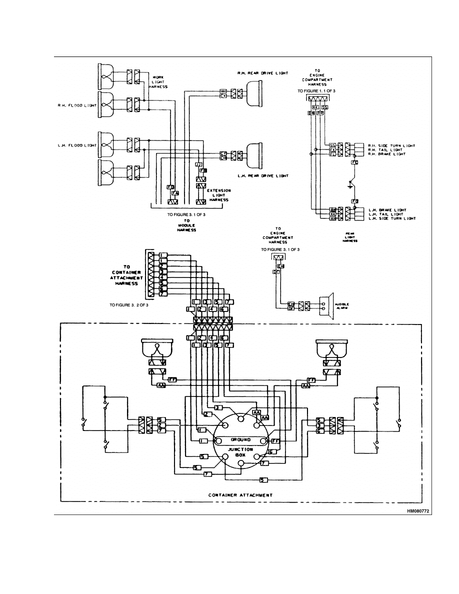
Diagrams, Schematics, or Arrangements
Figure 3. Electrical System Schematic (Sheet 2 of 3)
11
Diagrams, Schematics, or Arrangements
2200 SRM 679
12
2200 SRM 679
Diagrams, Schematics, or Arrangements
Figure 3. Electrical System Schematic (Sheet 3 of 3)
13

NOTES
____________________________________________________________
____________________________________________________________
____________________________________________________________
____________________________________________________________
____________________________________________________________
____________________________________________________________
____________________________________________________________
____________________________________________________________
____________________________________________________________
____________________________________________________________
____________________________________________________________
____________________________________________________________
____________________________________________________________
____________________________________________________________
____________________________________________________________
____________________________________________________________
____________________________________________________________
____________________________________________________________
____________________________________________________________
____________________________________________________________
14


TECHNICAL PUBLICATIONS
2200 SRM 679
11/03 (3/97) Printed in United Kingdom
Document Outline
- toc
Wyszukiwarka
Podobne podstrony:
1466193 2200SRM0755 (11 2001) UK EN
899784 2200SRM0002 (10 2003) UK EN
897820 2200SRM0595 (11 1995) UK EN
1475871 1800SRM0785 (11 2003) UK EN
899648 2240SRM0001 (11 2003) UK EN
1470230 1600SRM0786 (11 2003) UK EN
1466175 2200SRM0744 (09 2003) UK EN
1494953 1400SRM0944 (09 2003) UK EN
1466205 2100SRM0735 (11 2004) UK EN
więcej podobnych podstron