STEERING SYSTEM
YARDMASTER®
HR45-25, HR45-27, HR45-31, HR45-40S,
HR45-36L, HR45-40LS, HR45-45LSX,
HR45H [A227, B227]
PART NO. 1470230
1600 SRM 786

SAFETY PRECAUTIONS
MAINTENANCE AND REPAIR
• When lifting parts or assemblies, make sure all slings, chains, or cables are correctly
fastened, and that the load being lifted is balanced. Make sure the crane, cables, and
chains have the capacity to support the weight of the load.
• Do not lift heavy parts by hand, use a lifting mechanism.
• Wear safety glasses.
• DISCONNECT THE BATTERY CONNECTOR before doing any maintenance or repair
on electric lift trucks.
• Disconnect the battery ground cable on internal combustion lift trucks.
• Always use correct blocks to prevent the unit from rolling or falling. See HOW TO PUT
THE LIFT TRUCK ON BLOCKS in the Operating Manual or the Periodic Mainte-
nance section.
• Keep the unit clean and the working area clean and orderly.
• Use the correct tools for the job.
• Keep the tools clean and in good condition.
• Always use HYSTER APPROVED parts when making repairs. Replacement parts
must meet or exceed the specifications of the original equipment manufacturer.
• Make sure all nuts, bolts, snap rings, and other fastening devices are removed before
using force to remove parts.
• Always fasten a DO NOT OPERATE tag to the controls of the unit when making repairs,
or if the unit needs repairs.
• Be sure to follow the WARNING and CAUTION notes in the instructions.
• Gasoline, Liquid Petroleum Gas (LPG), Compressed Natural Gas (CNG), and Diesel fuel
are flammable. Be sure to follow the necessary safety precautions when handling these
fuels and when working on these fuel systems.
• Batteries generate flammable gas when they are being charged. Keep fire and sparks
away from the area. Make sure the area is well ventilated.
NOTE:
The following symbols and words indicate safety information in this
manual:
WARNING
Indicates a condition that can cause immediate death or injury!
CAUTION
Indicates a condition that can cause property damage!

Steering System YardMaster
®
Table of Contents
TABLE OF CONTENTS
General ...............................................................................................................................................................
Description .........................................................................................................................................................
Steering Control Unit Repair ............................................................................................................................
Description .....................................................................................................................................................
Operation .......................................................................................................................................................
Load-Sensing Steering ..................................................................................................................................
Remove ...........................................................................................................................................................
Disassemble ...................................................................................................................................................
Clean ..............................................................................................................................................................
Assemble ........................................................................................................................................................
Install .............................................................................................................................................................
Steering Axle Repair..........................................................................................................................................
Description .....................................................................................................................................................
Remove ...........................................................................................................................................................
Install .............................................................................................................................................................
Steering Cylinder Repair...................................................................................................................................
Remove ...........................................................................................................................................................
Clean and Inspect ..........................................................................................................................................
Assemble ........................................................................................................................................................
Install .............................................................................................................................................................
Hubs Repair .......................................................................................................................................................
Remove ...........................................................................................................................................................
Clean ..............................................................................................................................................................
Install .............................................................................................................................................................
Spindles Repair ..................................................................................................................................................
Remove ...........................................................................................................................................................
Install .............................................................................................................................................................
System Air Removal ..........................................................................................................................................
Relief Valve Adjustment for Steering System ..................................................................................................
Antitipping Device Adjustment.........................................................................................................................
Troubleshooting..................................................................................................................................................
This section is for the following models:
HR45-25, HR45-27, HR45-31, HR45-40S, HR45-36L, HR45-40LS,
HR45-45LSX, HR45H [A227, B227]
©2004 HYSTER COMPANY
i

"THE
QUALITY
KEEPERS"
HYSTER
APPROVED
PARTS
1600 SRM 786
Description
General
This section has the description and repair procedures for the parts of the steering system.
Description
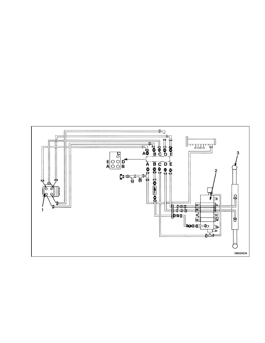
These vehicles use a hydraulic steering system. See
Figure 1 and Figure 2. The oil for the steering system
is supplied by the main hydraulic pump. Oil from
the pump flows to the main control valve, past a re-
lief valve, then to the steering control unit. The re-
lief valve for the steering system is set at 220 bar
(3200 psi).
When the engine is not running, a check valve closes
and permits the steering control unit to operate as a
hydraulic motor. The vehicle is difficult to steer when
the steering pump is not operating, but steering is
possible.
When the steering wheel is turned, a pilot line (LS)
from the steering control unit shifts a shuttle valve
in the main control valve. The shuttle valve moves
to send all of the oil from the pump to the steering
control unit. The other four lines at the steering con-
trol unit connect the supply, return, left, and right
steering cylinder ports. Return flow from the steer-
ing system is sent to the hydraulic tank.
1.
STEERING CONTROL UNIT
2.
MAIN CONTROL VALVE
3.
STEERING CYLINDER
Figure 1. Steering System Diagram
1
Description
1600 SRM 786
1.
STEERING CONTROL UNIT
2.
MANIFOLD BLOCK
3.
STEERING CYLINDER
4.
MAIN CONTROL VALVE
5.
TO MAIN CONTROL VALVE
6.
FROM HYDRAULIC TANK
7.
MAIN HYDRAULIC PUMP
8.
TO HYDRAULIC TANK
Figure 2. Steering System Schematic Diagram
2
1600 SRM 786
Steering Control Unit Repair
Steering Control Unit Repair
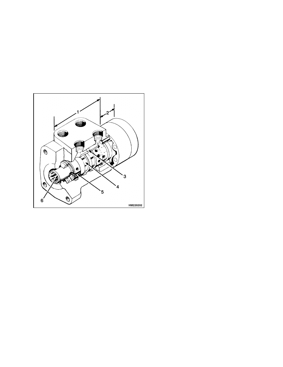
DESCRIPTION
The steering control unit is a hydrostatic unit con-
trolled by the steering wheel. See Figure 3. It is
mounted in the steering housing. The steering con-
trol unit has a shaft assembly, control section, and a
metering section. The hydraulic hoses for the steer-
ing system are fastened to a manifold block.
1.
CONTROL
SECTION
2.
METERING
SECTION
3.
CHECK BALL
(MANUAL
OPERATION)
4.
SLEEVE
5.
NEUTRAL
POSITION
SPRINGS
6.
SPOOL
Figure 3. Steering Control Unit
OPERATION
Turning the steering wheel actuates three main
parts of the steering control unit (see Figure 3): (1)
the spool for the control section, (2) the sleeve for
the control section, and (3) the rotor in the metering
section. When the steering wheel is not moving, the
spool and sleeve are held in the NEUTRAL (center)
position by springs. During this time, oil flows freely
through the steering control unit. The oil does not
flow to the steering cylinder.
As the steering wheel is turned, the spool just be-
gins to rotate. The springs try to move the sleeve to
keep the NEUTRAL position between the spool and
sleeve. However, the force necessary to turn the ro-
tor is greater than the pressure of the springs. The
springs begin to bend, letting the spool move a small
amount within the sleeve. The spool stops moving
when it touches the center pin. In this position, the
holes in the sleeve and the spool are aligned. Oil com-
ing into the control unit flows to the metering section.
More rotation of the steering wheel causes the spool
to rotate the pin. This action causes the rotation of
the sleeve and the rotor in the metering section. The
oil then flows to the flow amplifier and then to one
side of the steering cylinder. Oil from the other side
of the steering cylinder flows back through the flow
amplifier and the control section of the steering con-
trol unit.
When the steering wheel stops moving, the meter-
ing action in the metering section also stops. The
NEUTRAL position springs return the sleeve to the
NEUTRAL position. When this action occurs, the
pressure stays in the steering cylinder to keep the
tires in position. Oil from the pump flows through
the steering control unit to the tank or other parts of
the system. To return the tires to the straight posi-
tion, the steering wheel must be rotated in the oppo-
site direction. The steering control unit will operate
as described, but all parts will rotate in the opposite
direction.
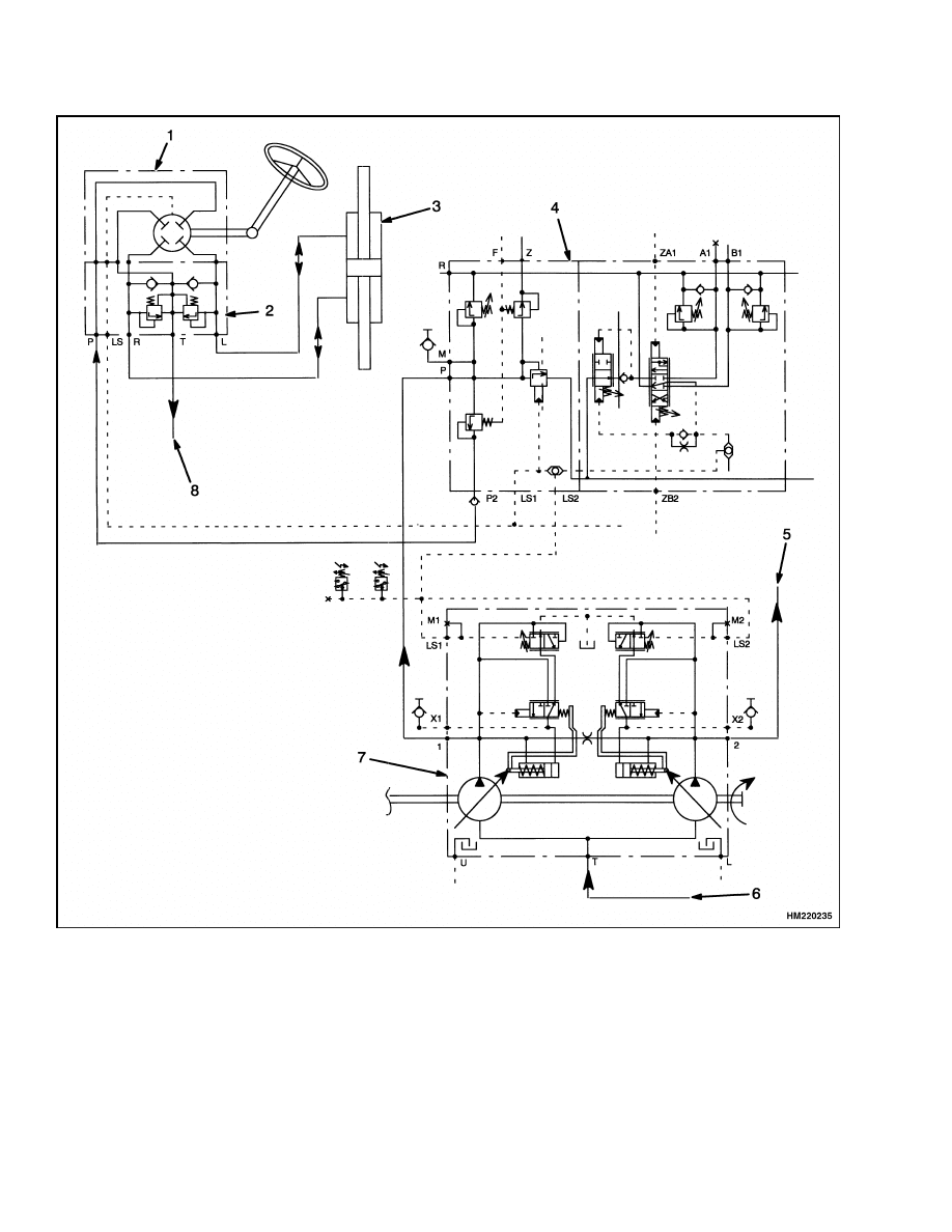
LOAD-SENSING STEERING
The demand for steering is sensed at the load-sensing
(LS) port in the steering control unit. The pilot line
from the LS port is connected to the priority valve
in the main control valve. While steering, a spring
and pilot pressure from the LS line hold the regulator
spool open for steering. When there is no pressure in
the LS line (no steering), pilot pressure from the hy-
draulic pump shifts the spool. In this position, most
of the oil for steering system goes to the hydraulic
system.
3
Steering Control Unit Repair
1600 SRM 786
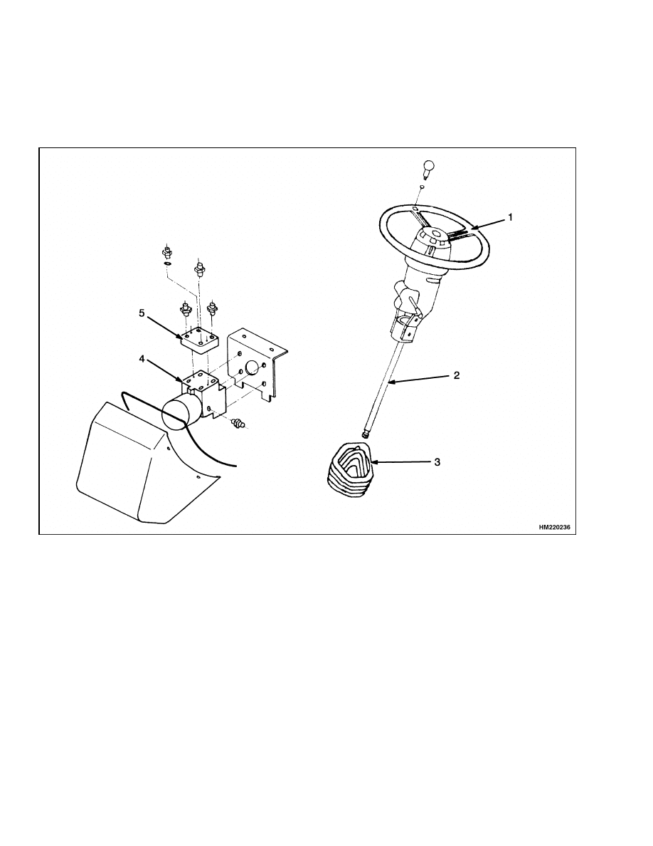
REMOVE
1.
Remove cover from steering housing. Put tags
on hydraulic lines at manifold block. Disconnect
hydraulic lines and put caps on openings.
2.
Remove steering column from steering control
unit. See Figure 4. Remove capscrews that fas-
ten steering control unit to bracket and remove
steering control unit.
1.
STEERING WHEEL
2.
STEERING COLUMN
3.
RUBBER BOOT
4.
STEERING CONTROL UNIT
5.
MANIFOLD BLOCK
Figure 4. Steering Column Assembly
4
1600 SRM 786
Steering Control Unit Repair
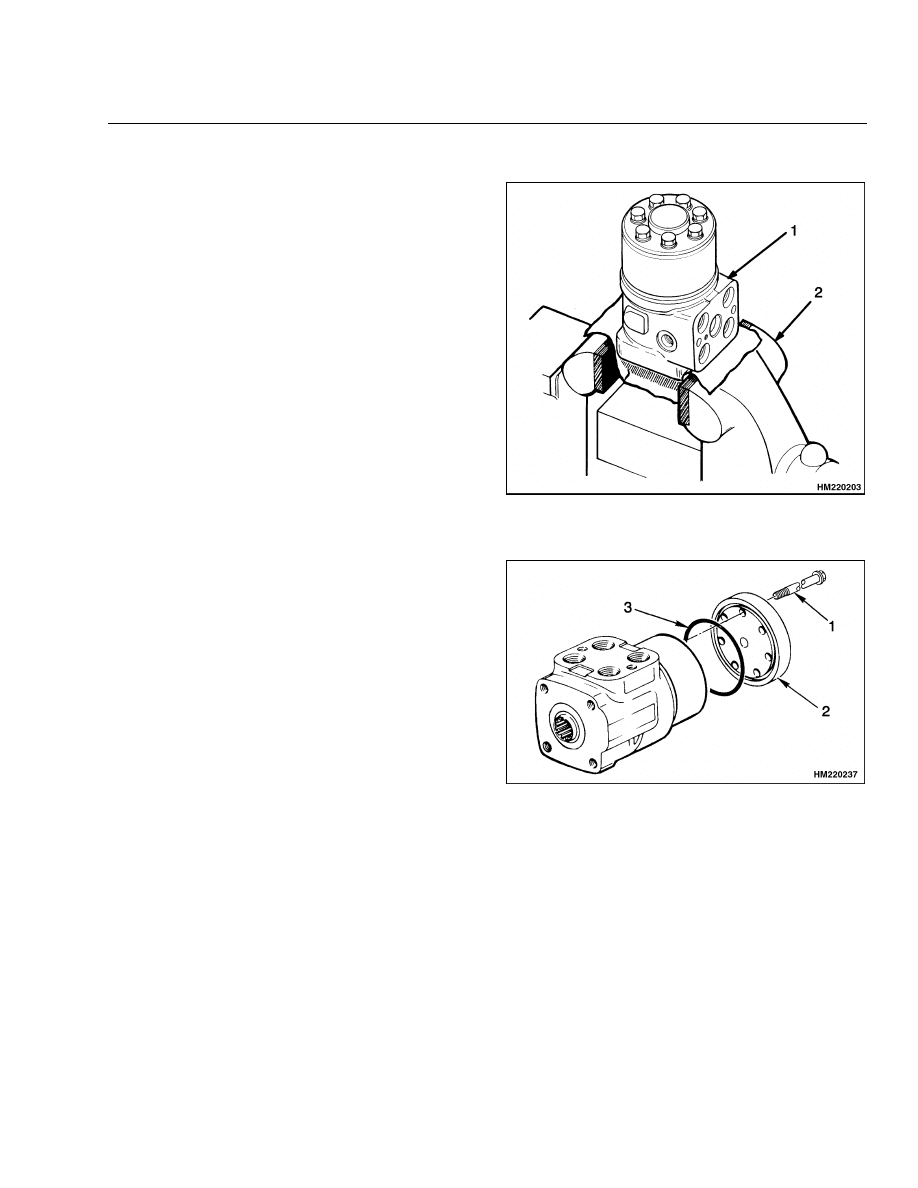
DISASSEMBLE
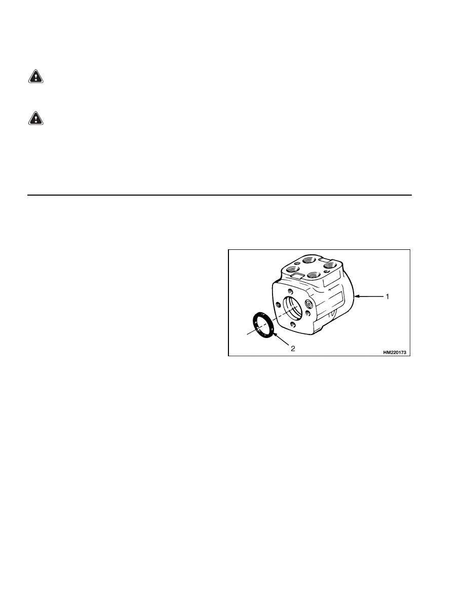
STEP 1.
Put the control unit in a vise with soft jaws. Make an
identification mark on length of control unit. Remove
manifold block.
1.
STEERING CONTROL UNIT
2.
VISE
STEP 2.
Remove cover on bottom of steering control unit.
1.
CAPSCREW
2.
COVER
3.
O-RING
5
Steering Control Unit Repair
1600 SRM 786
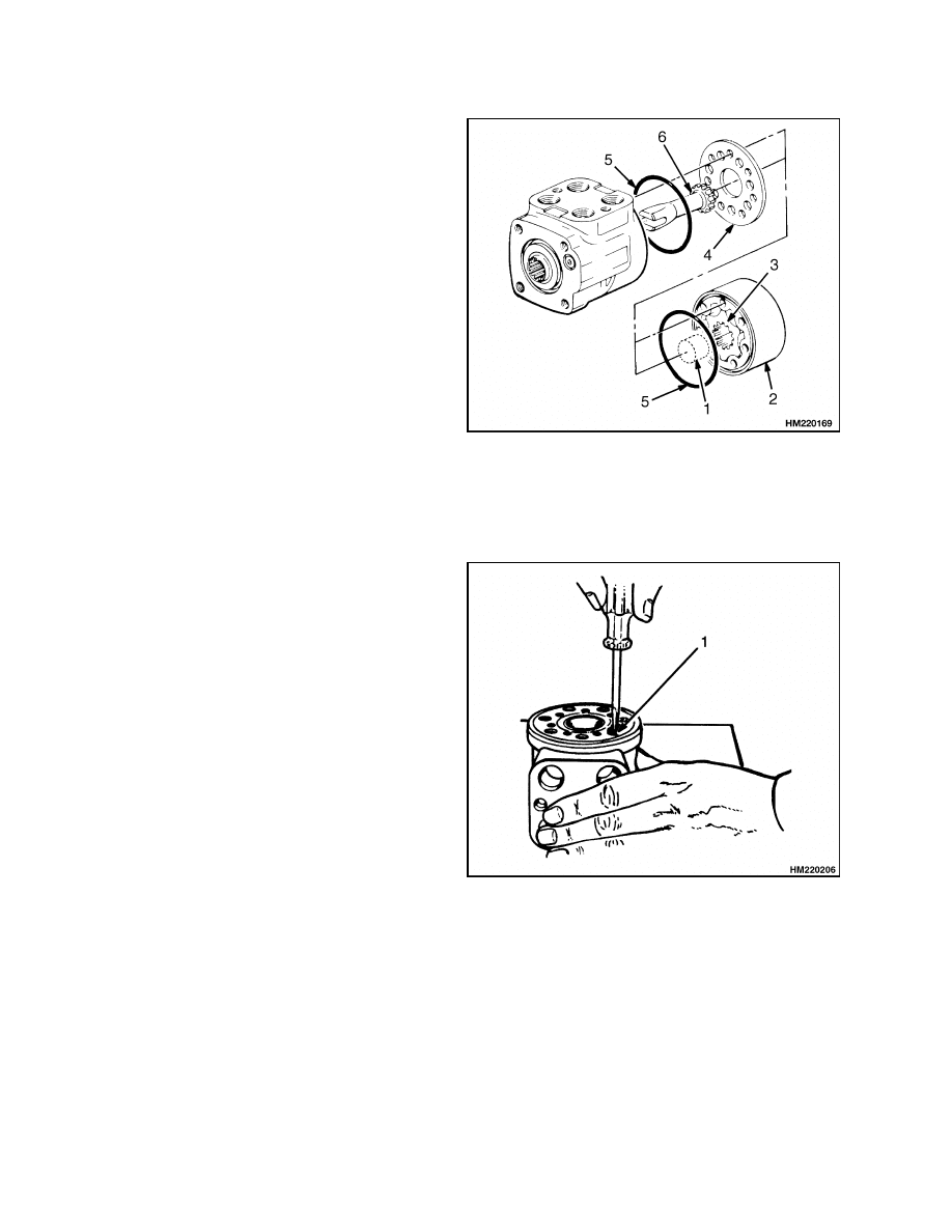
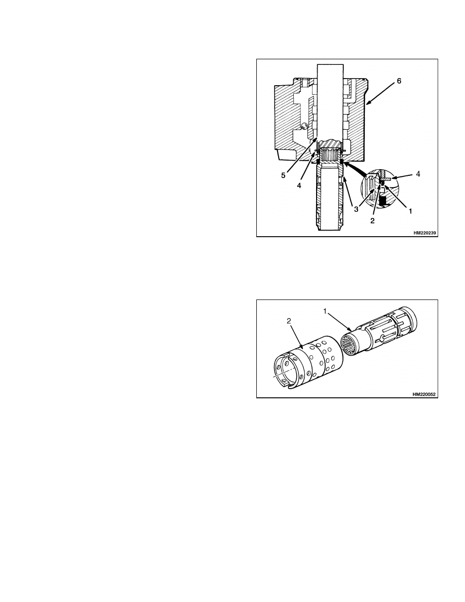
STEP 3.
Remove spacer, stator, rotor, and port plate. Put a
mark on stator so the same side is toward body of
control unit. Remove O-rings. Remove center shaft.
1.
SPACER
2.
STATOR
3.
ROTOR
4.
PORT PLATE
5.
O-RING
6.
CENTER SHAFT
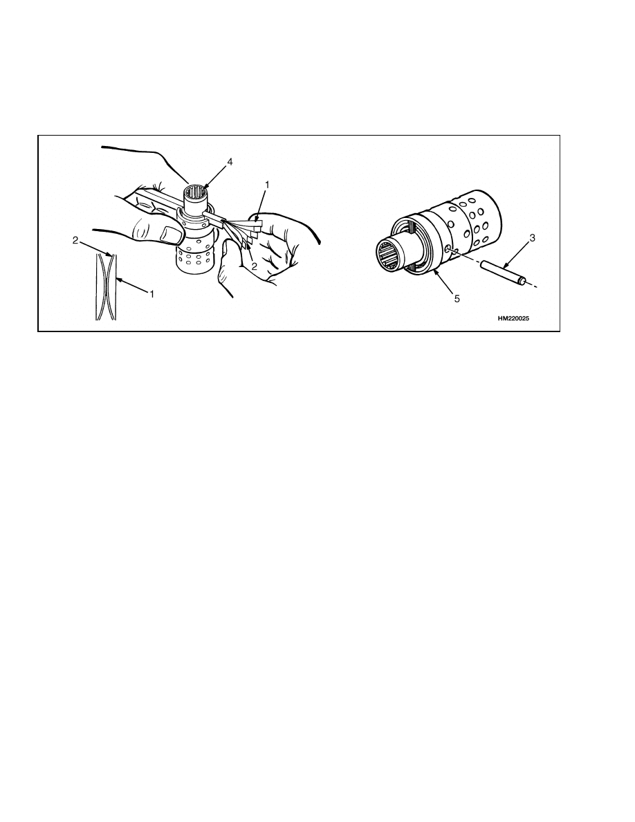
STEP 4.
Remove screw for check ball. Remove check ball.
1.
SCREW
6
1600 SRM 786
Steering Control Unit Repair
STEP 5.
Remove spool and sleeve assembly. Remove thrust bearing assembly from spool. Push center pin from sleeve.
Carefully remove spool from sleeve. (Rotate spool slowly during removal.) Remove ring from sleeve. Remove
NEUTRAL position springs from spool.
1.
SPOOL AND SLEEVE ASSEMBLY
2.
THRUST WASHER
3.
THRUST BEARING
4.
CENTER PIN
5.
SLEEVE
6.
SPOOL
7.
RING
8.
NEUTRAL POSITION SPRINGS
STEP 6.
Remove dust seal from housing.
1.
HOUSING
2.
DUST SEAL
7
Steering Control Unit Repair
1600 SRM 786
CLEAN
WARNING
Cleaning solvents can be flammable and toxic and can cause skin irritation. When using cleaning
solvents, always follow the solvent manufacturer’s recommended safety precautions.
WARNING
Compressed air can move particles so they cause injury to the user or to other personnel. Make
sure the path of the compressed air is away from all personnel. Wear protective goggles or a face
shield to prevent injury to the eyes.
Clean all parts in solvent. Dry parts with compressed air. Do not dry parts with a cloth. Make sure all surfaces
are free of scratches and sharp edges.
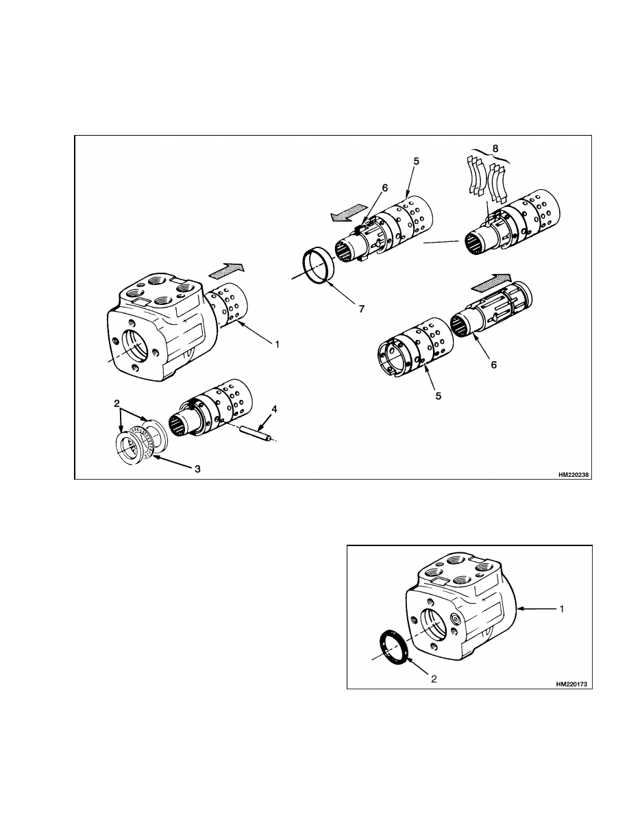
ASSEMBLE
NOTE:
Use new seals, O-rings, and NEUTRAL position springs during assembly. Lubricate all parts with
clean hydraulic oil.
STEP 1.
Install new dust seal in housing.
1.
HOUSING
2.
DUST SEAL
8
1600 SRM 786
Steering Control Unit Repair
STEP 2.
Put spool on workbench, then put housing onto spool
as shown. Install guide ring with O-ring on the end
of spool. Put a large thrust washer (see STEP 5) on
top of guide ring and O-ring assembly. Use a deep
socket or tube to push on washer, and install O-ring
and guide ring in housing. Carefully remove washer,
tube, and spool from housing.
1.
O-RING
2.
GUIDE RING
3.
SPOOL
4.
WASHER
5.
TUBE
6.
HOUSING
STEP 3.
Carefully assemble spool and sleeve. Make sure spool
rotates freely in sleeve.
1.
SPOOL
2.
SLEEVE
9
Steering Control Unit Repair
1600 SRM 786
STEP 4.
Assemble NEUTRAL position springs, then push them into position in spool. Make sure flat springs are in-
stalled to the outside of curved springs. Install center pin. Install ring on sleeve (over NEUTRAL position
springs). The ring must turn freely on the sleeve.
1.
NEUTRAL POSITION SPRINGS (FLAT)
2.
NEUTRAL POSITION SPRINGS (CURVED)
3.
CENTER PIN
4.
SPOOL
5.
RING
10
1600 SRM 786
Steering Control Unit Repair
STEP 5.
Install thrust washers and thrust bearing on spool.
Make sure chamfer on inner thrust washer is toward
sleeve. Install spool and sleeve assembly in housing.
Carefully rotate spool and sleeve assembly during
installation to make sure spool fits correctly in seal
installed in STEP 2. Make sure center pin in spool
and sleeve assembly is horizontal (parallel to port
surface).
1.
HOUSING
2.
SPOOL AND SLEEVE ASSEMBLY
3.
THRUST WASHER
4.
THRUST BEARING
5.
SPOOL
6.
SLEEVE
STEP 6.
Install check ball and sleeve. Make sure the sleeve is even with or below the surface of the housing. Lubricate
O-ring and install O-ring and port plate. Align holes in port plate with holes in housing.
1.
CHECK BALL SLEEVE
2.
HOUSING
3.
O-RING
4.
PORT PLATE
11
Steering Control Unit Repair
1600 SRM 786
STEP 7.
Install center shaft so it engages with center pin in spool and sleeve assembly. Make sure the center pin is
still parallel to the port surface. Install rotor on center shaft. Make sure a valley in the rotor aligns with slot
(center pin) in center shaft. Install O-ring and stator. Make sure to align the marks made during disassembly.
1.
CENTER SHAFT
2.
CENTER PIN
3.
ROTOR
4.
STATOR
5.
O-RING
12
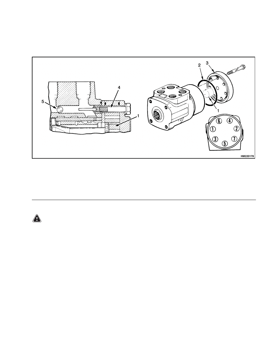
1600 SRM 786
Steering Control Unit Repair
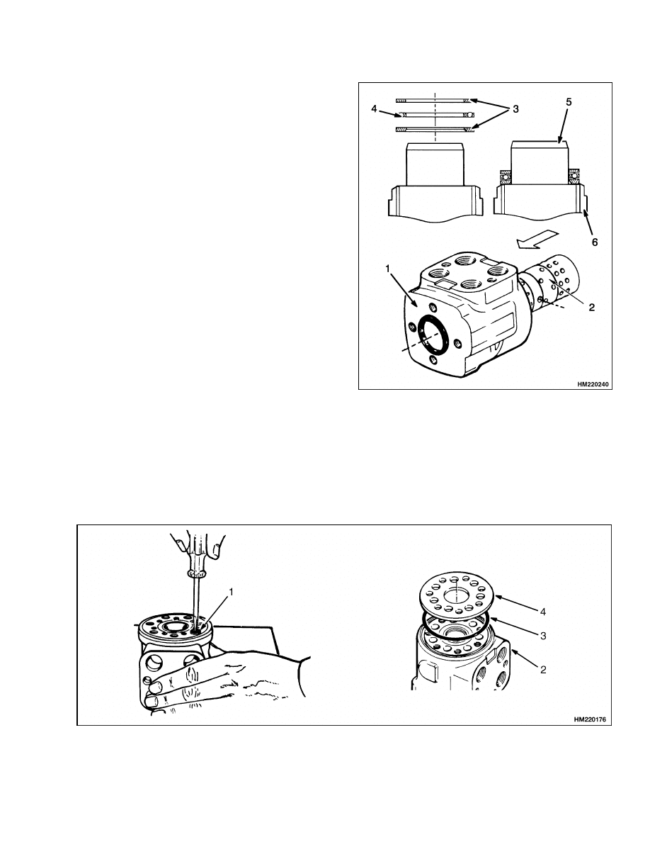
STEP 8.
Install spacer. Install O-ring and cover. Tighten capscrews for the cover, in the sequence shown, to 17 N•m
(150 lbf in). Then tighten them to 30 N•m (265 lbf in). Make sure the capscrew with the pin fits in the hole for
the check ball.
1.
SPACER
2.
O-RING
3.
COVER
4.
CAPSCREW
5.
CHECK BALL
STEP 9.
Install manifold block and O-rings on steering control unit.
INSTALL
WARNING
After making repairs, do not extend the hands
or arms through the center of the steering
wheel. If the control unit was not assembled
correctly, or hoses are not connected correctly,
it can rotate with a strong force and cause
injury. If this action occurs, disassemble the
control unit and correct the problem.
1.
Install control unit on bracket. See Figure 4.
Connect lines at manifold block and steering con-
trol unit.
2.
Connect steering column. Install housing.
13
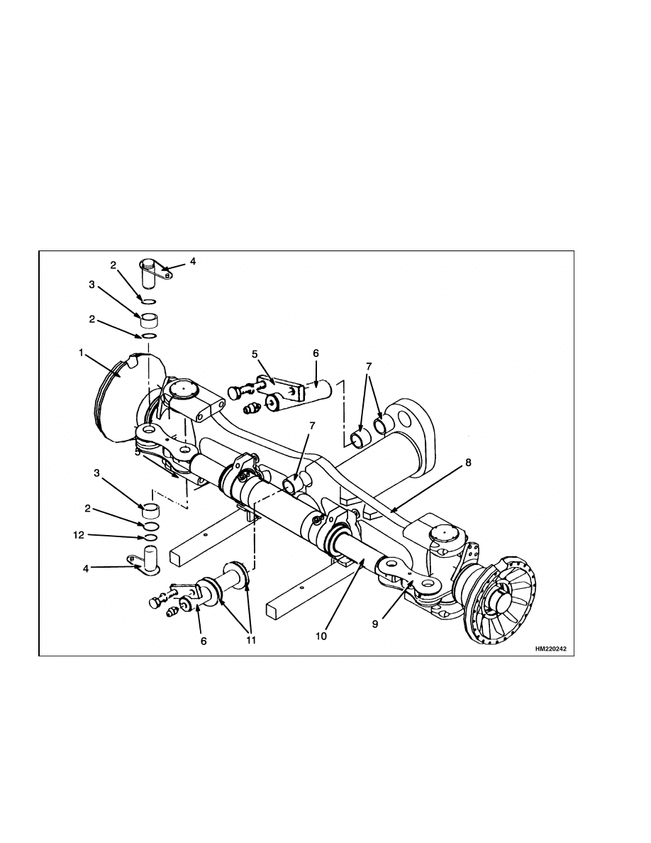
Steering Axle Repair
1600 SRM 786
Steering Axle Repair
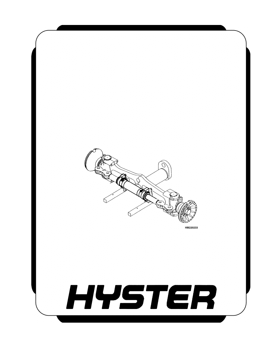
DESCRIPTION
The steering axle assembly includes an axle frame,
a steering cylinder, and two spindle and hub assem-
blies. See Figure 5. The axle assembly is connected
to the frame with two pivot shafts. The ends of the
axle and steer wheels can move up and down when
the vehicle travels over rough surfaces.
The ends of the piston rod extend from both ends of
the steering cylinder shell. Tie rods connect the spin-
dle arms to the cylinder rod. Oil pressure on one side
of the piston moves the piston in the bore. The piston
pushes an equal amount of oil from the opposite side
of the cylinder.
A relief valve in the steering system controls the oil
pressure when the piston reaches the end of the cylin-
der.
1.
HUB
2.
LOCK RING
3.
BUSHING
4.
PIN
5.
PLATE
6.
PIVOT PIN
7.
PIVOT BUSHING
8.
AXLE FRAME
9.
TIE ROD
10. STEERING CYLINDER
11. WASHER SET
12. WASHER
Figure 5. Steering Axle Assembly
14

1600 SRM 786
Steering Cylinder Repair
REMOVE
WARNING
Put the rear of the vehicle on blocks. Follow
the procedures for raising the vehicle in the
Operating Manual or Periodic Maintenance
section. The surface must be solid, even, and
level. Make sure any blocks used to support
the vehicle are solid, one piece units. Make
sure the lifting devices used during repairs
can lift the weight of the parts.
1.
Remove counterweight.
[The counterweight
weighs approximately 17,000 kg (37,500 lb).]
See Figure 5. When removing axle, disconnect
hydraulic lines and install caps on cylinder fit-
tings. The caps will prevent cylinder rod from
moving as axle is removed.
2.
Put a lifting device under the axle.
Remove
plates that hold pivot pins in frame. Remove
pivot pins. Lower axle from frame and remove
axle.
INSTALL
1.
When installing axle, make sure washer sets
and bushing are in correct position.
See Fig-
ure 5. Lubricate bushings and pivot shafts with
multipurpose grease.
Raise axle into frame
mounts. Install pivot shafts and plates. Install
counterweight. [The counterweight weighs ap-
proximately 17,000 kg (37,500 lb).]
2.
Check the operation of the antitipping device as
described in Antitipping Device Adjustment.
Steering Cylinder Repair
REMOVE
WARNING
Make sure the lifting devices used during re-
pairs can lift the weight of the parts.
1.
Remove counterweight.
[The counterweight
weighs approximately 17,000 kg (37,500 lb).]
Disconnect hydraulic lines and install caps on
cylinder fittings. See Figure 5.
2.
Disconnect tie rods at cylinder.
Remove cap-
screws that hold cylinder to axle frame. Remove
cylinder.
CLEAN AND INSPECT
WARNING
Cleaning solvents can be flammable and toxic,
and can cause skin irritation.
When using
cleaning solvents, always follow the solvent
manufacturer’s recommended safety precau-
tions.
WARNING
Compressed air can move particles so they
cause injury to the user or to other personnel.
Make sure the path of the compressed air is
away from all personnel. Wear protective gog-
gles or a face shield to prevent injury to the
eyes.
Clean all parts in solvent. Dry parts with compressed
air. Make sure all surfaces are free of scratches and
sharp edges.
1.
Inspect piston rod for grooves or damage.
2.
Inspect brackets on cylinder for cracks.
ASSEMBLE
1.
Repair cylinder as necessary using new seals and
O-rings. Lubricate parts with hydraulic oil dur-
ing assembly.
2.
Install retainers at ends of cylinder.
INSTALL
WARNING
Make sure the lifting devices used during re-
pairs can lift the weight of the parts.
1.
Install hydraulic fittings on cylinder.
Install
cylinder and mounting blocks on axle frame.
Tighten capscrews that hold cylinder to axle
frame to 500 N•m (370 lbf ft).
2.
Connect tie rods to cylinder. (See Figure 5.)
3.
Install counterweight.
[The counterweight
weights approximately 17,000 kg (37,500 lb).]
15
Hubs Repair
1600 SRM 786
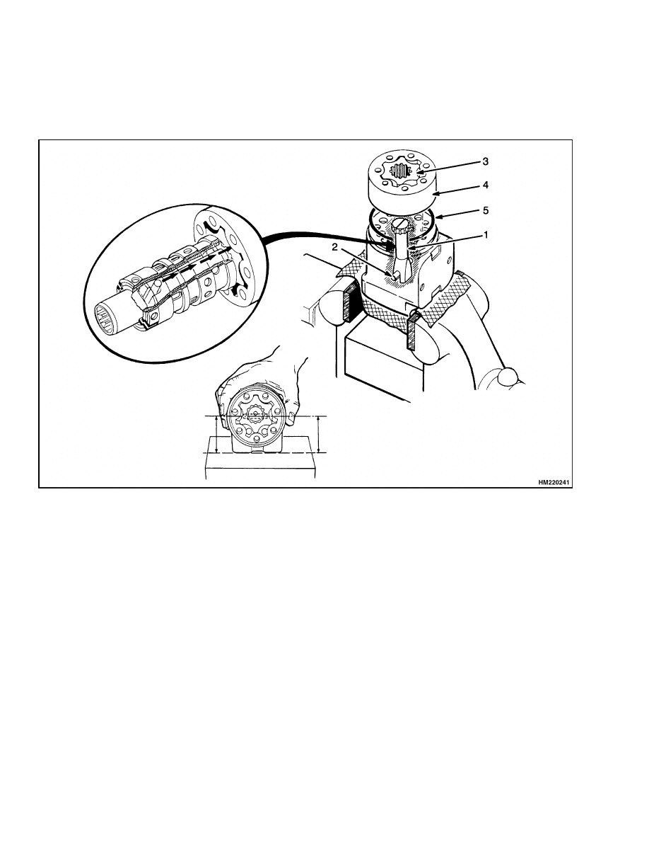
Hubs Repair
REMOVE
Remove hub cover. See Figure 6. Remove adjust-
ment nuts and lock ring. Remove hub. If the bear-
ings or the seals are replaced, use a brass drift to re-
move inner bearing assembly from hub. Check for
damage or wear on bearings.
CLEAN
WARNING
Cleaning solvents can be flammable and toxic
and can cause skin irritation.
When using
cleaning solvents, always follow the solvent
manufacturer’s recommended safety proce-
dures.
Clean all parts with solvent. Make sure bearings are
clean.
INSTALL
1.
Lubricate bearings with multipurpose grease.
See Figure 6. Install the inner bearing and seal.
Install hub, outer bearing, washer, and adjust-
ment nut on spindle. Tighten adjustment nut
while rotating hub.
2.
Install lock ring against adjustment nut. Tighten
adjusting nut a small amount until tab on lock
ring aligns with a notch in adjustment nut. Bend
tab on lock ring to lock adjustment nut.
3.
Install outer adjustment nut and tighten it.
Bend tab on lock ring to lock the nut.
4.
Fill hub with multipurpose grease. Install hub
cover.
1.
HUB COVER
2.
LOCK RING
3.
WASHER
4.
HUB
5.
SPINDLE
6.
SEAL
7.
BEARING CAP
8.
CAP
9.
BUSHING
10. KING PIN
11. CAPSCREW
12. AXLE FRAME
13. BEARING
14. ADJUSTMENT NUT
Figure 6. Hub and Spindle
16
1600 SRM 786
Relief Valve Adjustment for Steering System
Spindles Repair
REMOVE
WARNING
Completely remove the air pressure from the
tires before removing the wheels from the ve-
hicle. Air pressure in the tires can cause the
tire and rim parts to explode, causing serious
injury or death.
Always wear safety glasses.
1.
Remove wheels from steering axle to service
spindles.
See Figure 6.
Remove hubs.
Dis-
connect tie rod from spindle. Remove caps for
spindle.
2.
Connect lifting device to spindle. Remove cap-
screws that hold bearing caps to axle frame.
3.
Remove spindle assembly from axle.
INSTALL
1.
Lubricate thrust washers and bushings with
multipurpose grease.
See Figure 6.
Install
thrust washers and seals on spindle.
Install
bushings on spindle.
2.
Install spindle assembly in axle frame. Install
bearing cap and capscrews. Tighten capscrews.
3.
Install caps for spindle.
4.
Connect tie rod to spindle. (See Figure 5.) Install
hubs as described in Hubs Repair.
System Air Removal
Air can enter the system when a hydraulic line is dis-
connected. If the operation is rough, start the en-
gine and rotate the steering wheel stop to stop sev-
eral times in each direction. The air will be removed
without disconnecting any lines. If the operation is
still rough, air can be entering the system at a loose
fitting.
Relief Valve Adjustment for Steering System
WARNING
Before disconnecting any hydraulic lines or fit-
tings, release pressure from the hydraulic cir-
cuit as follows:
1.
Shut the engine off and completely lower
the boom.
2.
Operate the joystick and the brake pedals
until the hydraulic pressure is released.
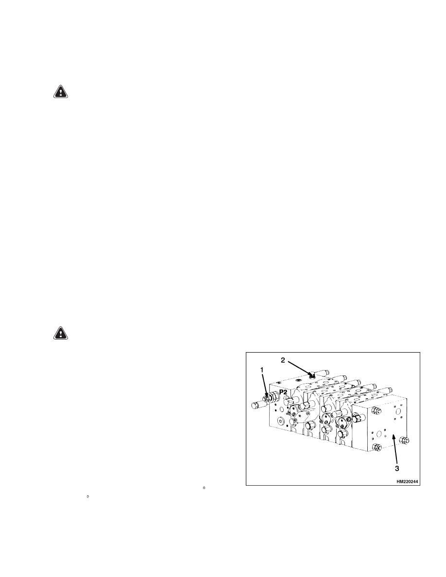
The relief valve for the steering system is in the main
control valve. See Figure 7. Adjust the setting of the
relief valve for the steering system as follows:
1.
Install pressure gauge of 600 bar (8700 psi) at
main pressure test port (M) on main control
valve.
2.
Start engine.
Operate hydraulic system until
temperature of hydraulic oil is 55 to 65 C (130
to 150 F).
3.
With engine at full throttle, adjust main regu-
lators to 420 bar (6100 psi). With the steering
cylinder at full stroke, adjust relief valve (P2) to
obtain 220 bar (3200 psi).
1.
STEERING RELIEF VALVE 220 bar (3200 psi)
2.
MAIN PRESSURE TEST PORT
3.
MAIN CONTROL VALVE
Figure 7. Steering Relief Valve
17
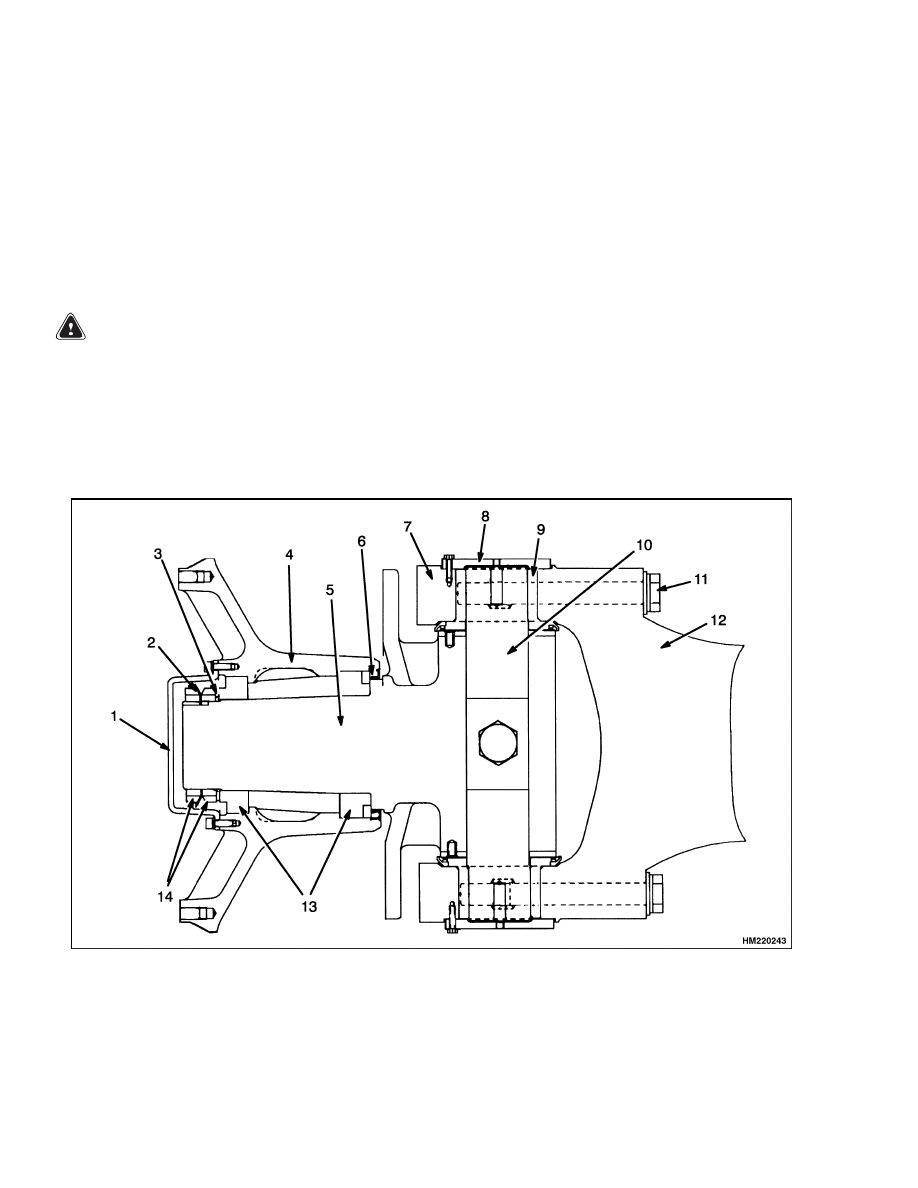
Antitipping Device Adjustment
1600 SRM 786
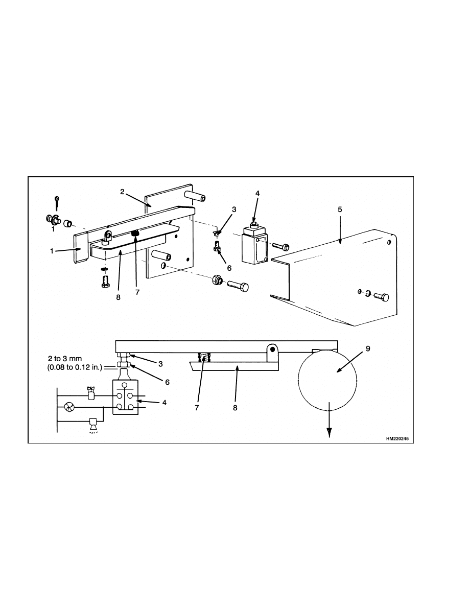
Antitipping Device Adjustment
NOTE:
At 75% of the tipping load, the complete ve-
hicle lifts up except the steering axle. The steering
axle equals 25% of the tipping load.
1.
Pick up load of approximately 12 to 15 metric ton
(26,000 to 33,000 lb).
2.
Raise load 75 mm (3 in.) from ground. Extend
boom slowly to shift weight forward and remove
weight from steering axle. Lower load to ground
and make sure steering tires contact the ground.
3.
Remove cover for switch. See Figure 8. Loosen
lock nut for the adjustment bolt. Turn adjust-
ment bolt clockwise until spring bracket is loose.
Check that clearance between switch and adjust-
ment bolt is 2 to 3 mm (0.08 to 0.12 in.). (When
switch is open, warning light is on and alarm
sounds.) Tighten lock nut. Install cover.
4.
Release load on vehicle and antitipping mecha-
nism will return to its normal position.
1.
LINK
2.
SUPPORT
3.
LOCK NUT
4.
SWITCH
5.
COVER
6.
ADJUSTMENT BOLT
7.
SPRING
8.
SPRING BRACKET
9.
STEERING AXLE
Figure 8. Antitipping Device
18

1600 SRM 786
Troubleshooting
Troubleshooting
PROBLEM
POSSIBLE CAUSE
PROCEDURE OR ACTION
There is no action when the
steering wheel is turned.
Oil level is low. There is no oil in
tank.
Fill tank to correct level.
Lines are loose at control unit or
manifold block.
Tighten oil lines.
Sleeve and spool in control unit will
not move.
Replace control unit.
The vehicle steers slowly.
The steering wheel is hard
to turn.
Oil level is low. There is no oil in
tank.
Fill tank to correct level.
Lines to control unit are damaged.
Replace oil lines.
Sleeve and spool in control unit are
worn.
Replace control unit.
Parts of metering section are worn.
Replace control unit.
Check valve in control unit does not
open.
Replace control unit.
The steering wheel turns the
tires in the wrong direction.
Lines at control unit are not correctly
connected.
Connect lines correctly.
Metering rotor in control unit is not
correctly aligned.
Assemble control unit correctly.
The tires continue to turn af-
ter the steering wheel stops.
NEUTRAL position springs in con-
trol unit are broken.
Repair or replace control unit.
Sleeve or spool in control unit has
damage.
Replace control unit.
19

NOTES
____________________________________________________________
____________________________________________________________
____________________________________________________________
____________________________________________________________
____________________________________________________________
____________________________________________________________
____________________________________________________________
____________________________________________________________
____________________________________________________________
____________________________________________________________
____________________________________________________________
____________________________________________________________
____________________________________________________________
____________________________________________________________
____________________________________________________________
____________________________________________________________
____________________________________________________________
____________________________________________________________
____________________________________________________________
____________________________________________________________
20


TECHNICAL PUBLICATIONS
1600 SRM 786
11/03 (1/00) Printed in United Kingdom
Document Outline
- toc
- Steering System YardMaster®
- Safety Precautions Maintenance and Repair
- General
- Description
- Steering Control Unit Repair
- Steering Axle Repair
- Steering Cylinder Repair
- Hubs Repair
- Spindles Repair
- System Air Removal
- Relief Valve Adjustment for Steering System
- Antitipping Device Adjustment
- Troubleshooting
Wyszukiwarka
Podobne podstrony:
1452929 2200SRM0679 (11 2003) UK EN
897493 1600SRM0512 (11 1995) UK EN
1466241 1600SRM0732 (10 2003) UK EN
1475871 1800SRM0785 (11 2003) UK EN
897993 1600SRM0671 (09 2003) UK EN
899648 2240SRM0001 (11 2003) UK EN
897392 1600SRM0451 (09 2003) UK EN
1466235 1600SRM0733 (09 2003) UK EN
910076 1600SRM0054 (10 2003) UK EN
1494140 1600SRM0936 (09 2003) UK EN
1452929 2200SRM0679 (11 2003) UK EN
897493 1600SRM0512 (11 1995) UK EN
więcej podobnych podstron