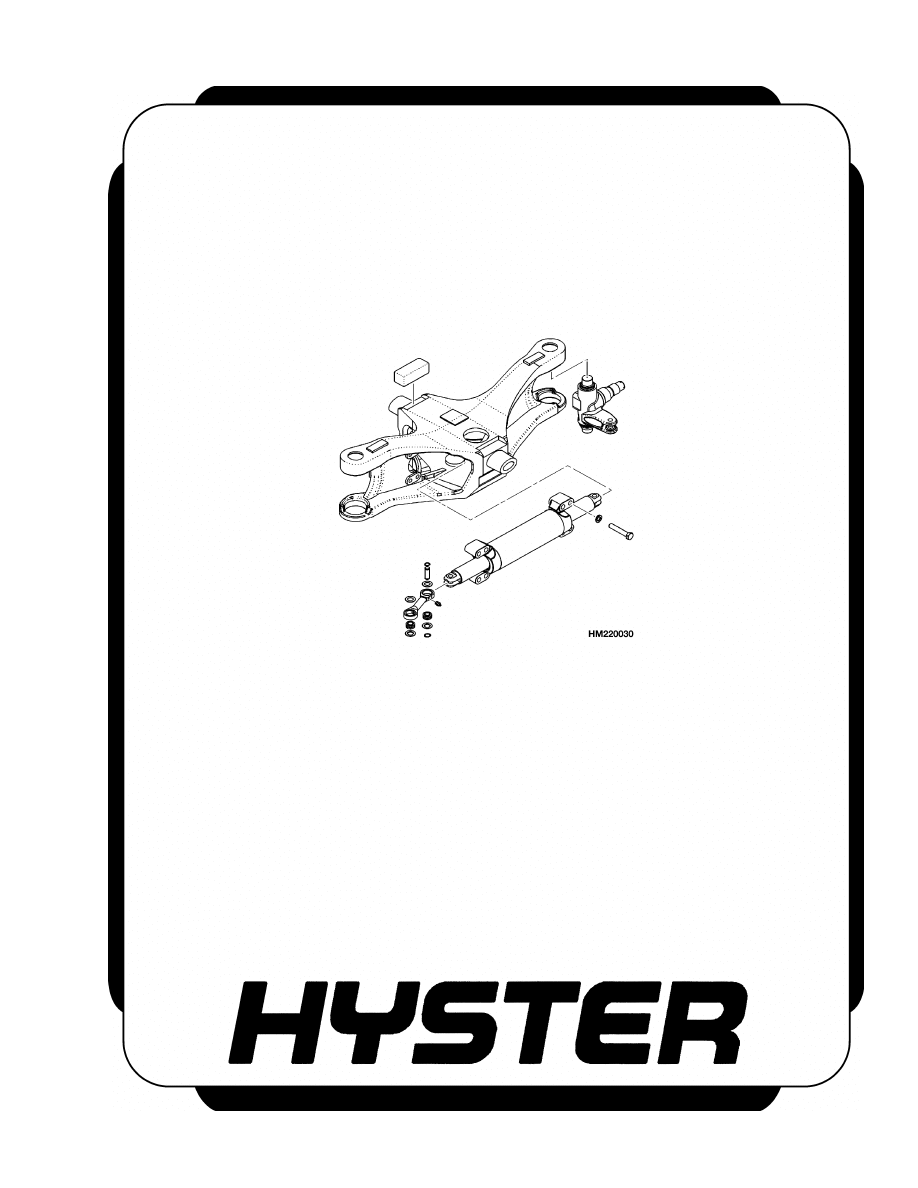
STEERING AXLE
H3.50-5.50XM (H70-120XM) [K005, L005]
PART NO. 1466235
1600 SRM 733

SAFETY PRECAUTIONS
MAINTENANCE AND REPAIR
• When lifting parts or assemblies, make sure all slings, chains, or cables are correctly
fastened, and that the load being lifted is balanced. Make sure the crane, cables, and
chains have the capacity to support the weight of the load.
• Do not lift heavy parts by hand, use a lifting mechanism.
• Wear safety glasses.
• DISCONNECT THE BATTERY CONNECTOR before doing any maintenance or repair
on electric lift trucks.
• Disconnect the battery ground cable on internal combustion lift trucks.
• Always use correct blocks to prevent the unit from rolling or falling. See HOW TO PUT
THE LIFT TRUCK ON BLOCKS in the Operating Manual or the Periodic Mainte-
nance section.
• Keep the unit clean and the working area clean and orderly.
• Use the correct tools for the job.
• Keep the tools clean and in good condition.
• Always use HYSTER APPROVED parts when making repairs. Replacement parts
must meet or exceed the specifications of the original equipment manufacturer.
• Make sure all nuts, bolts, snap rings, and other fastening devices are removed before
using force to remove parts.
• Always fasten a DO NOT OPERATE tag to the controls of the unit when making repairs,
or if the unit needs repairs.
• Be sure to follow the WARNING and CAUTION notes in the instructions.
• Gasoline, Liquid Petroleum Gas (LPG), Compressed Natural Gas (CNG), and Diesel fuel
are flammable. Be sure to follow the necessary safety precautions when handling these
fuels and when working on these fuel systems.
• Batteries generate flammable gas when they are being charged. Keep fire and sparks
away from the area. Make sure the area is well ventilated.
NOTE:
The following symbols and words indicate safety information in this
manual:
WARNING
Indicates a condition that can cause immediate death or injury!
CAUTION
Indicates a condition that can cause property damage!
Steering Axle
Table of Contents
TABLE OF CONTENTS
General ...............................................................................................................................................................
Description .........................................................................................................................................................
Steering Axle Assembly Repair.........................................................................................................................
Remove ...........................................................................................................................................................
Install .............................................................................................................................................................
Wheels and Hub Repair.....................................................................................................................................
Remove and Disassemble ..............................................................................................................................
Clean ..............................................................................................................................................................
Inspect ............................................................................................................................................................
Assemble and Install .....................................................................................................................................
Spindles and Bearings Repair...........................................................................................................................
Remove ...........................................................................................................................................................
Clean ..............................................................................................................................................................
Inspect ............................................................................................................................................................
Assemble and Install .....................................................................................................................................
Tie Rods Repair ..................................................................................................................................................
Remove ...........................................................................................................................................................
Clean ..............................................................................................................................................................
Inspect ............................................................................................................................................................
Install .............................................................................................................................................................
Steering Cylinder Repair...................................................................................................................................
Remove and Disassemble ..............................................................................................................................
Clean and Inspect ..........................................................................................................................................
Assemble and Install .....................................................................................................................................
Troubleshooting..................................................................................................................................................
This section is for the following models:
H3.50-5.50XM (H70-120XM) [K005, L005]
©2003 HYSTER COMPANY
i

"THE
QUALITY
KEEPERS"
HYSTER
APPROVED
PARTS
1600 SRM 733
Description
General
This section has the description and repair procedures for the steering axle. For information on the steering
control unit, see the section Steering Control Unit 1600 SRM 732.
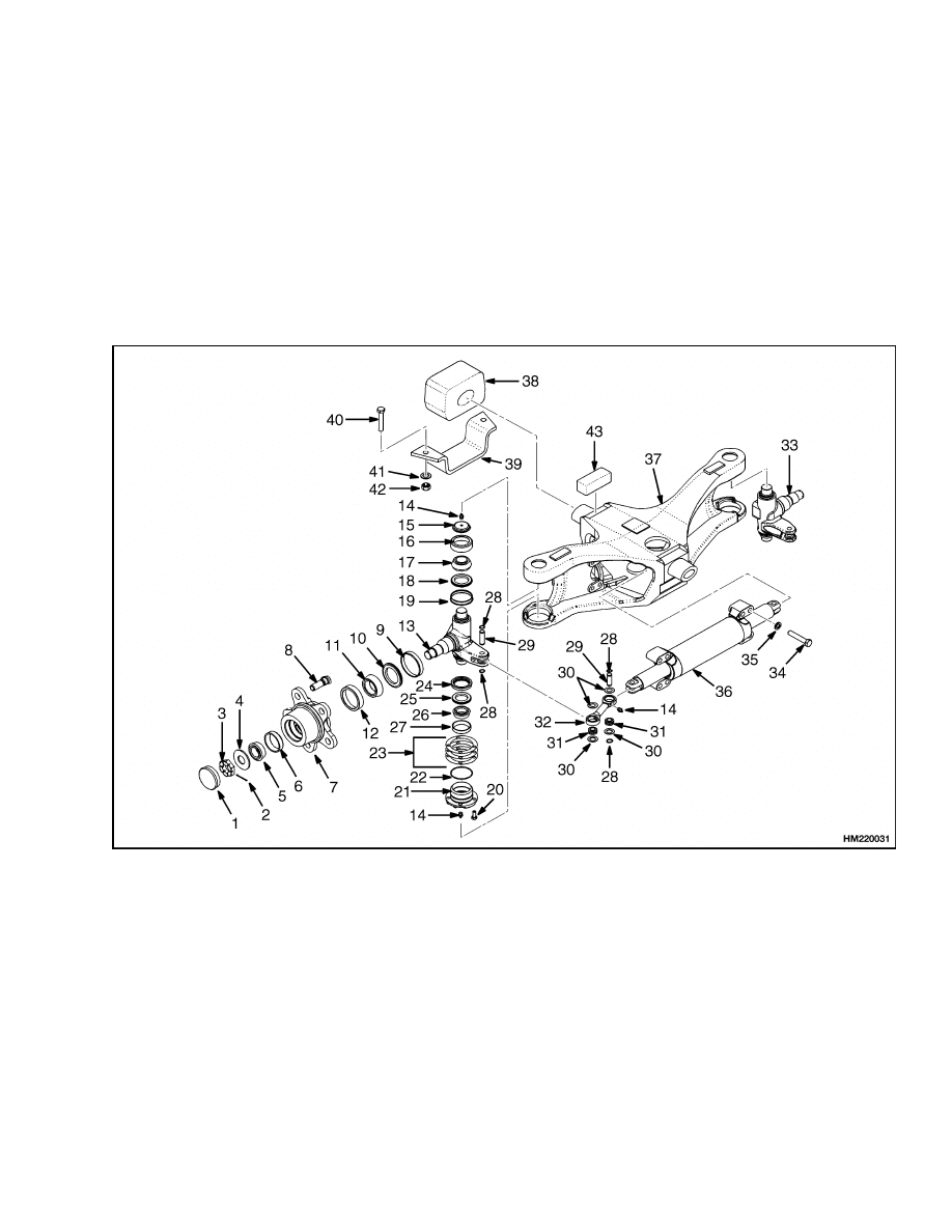
Description
The steering axle assembly includes an axle frame,
steering cylinder, tie rods, and two spindle and hub
assemblies. See Figure 1. The steering axle is con-
nected to the frame with center pivot mounts. The
center pivot mounts are rubber and permit the steer-
ing axle to move in the frame mount when the lift
truck travels over rough surfaces.
1.
HUB CAP
2.
COTTER PIN
3.
CASTLE NUT
4.
WASHER
5.
OUTER BEARING
6.
BEARING CUP
7.
HUB
8.
WHEEL STUD
9.
WEAR SLEEVE
10. OIL SEAL
11. INNER BEARING
12. BEARING CUP
13. LH SPINDLE
14. LUBRICATION FITTING
15. CAP
16. BEARING CUP
17. BEARING
18. SEAL
19. WEAR SLEEVE
20. CAPSCREW
21. BEARING CAP
22. O-RING
23. SHIMS
24. SEAL
25. SEAL
26. BEARING
27. BEARING CUP
28. SNAP RING
29. PIN
30. SEAL
31. SPHERICAL BEARING
32. TIE ROD
33. RH SPINDLE
34. CAPSCREW
35. LOCKWASHER
36. STEERING CYLINDER
37. STEER AXLE HOUSING
38. RUBBER MOUNT
39. BRACKET
40. CAPSCREW
41. WASHER
42. NUT
43. MOUNT
Figure 1. Steering Axle
1
Steering Axle Assembly Repair
1600 SRM 733
The end caps of the steering cylinder are also the
mounts for the cylinder and are held to the axle by
capscrews. The ends of the piston rod extend from
both ends of the cylinder. A single piston and the
seal are at the center of the piston rod. Oil pressure
on one side of the piston moves the piston in the bore.
The piston pushes an equal amount of oil from the
opposite side of the cylinder. The oil returns to the
steering control unit.
When the piston in the steering cylinder reaches the
end of the stroke, a relief valve controls the oil pres-
sure. The relief valve for the steering system is in
the manifold block that is installed on the steering
control unit.
Each spindle turns on two tapered roller bearings in
the axle frame. The preload on the bearings is con-
trolled by shims at the lower bearing cap. The tie
rods that connect the spindle arms to the cylinder do
not have an adjustment.
The wheel hubs rotate on two tapered roller bear-
ings and are held on the spindles by a castle nut.
The bearing preload of the wheel hubs is adjusted by
the castle nut. The grease seals protect the bearings
from dirt and water. Wear sleeves prevent the seals
from causing wear on the hub.
Steering Axle Assembly Repair
REMOVE
WARNING
Put the lift truck on blocks. Follow the proce-
dures for raising the lift truck described in the
Operating Manual. The surface must be solid,
even, and level. Make sure the blocks are solid,
one-piece units. Make sure the lifting devices
used during repairs can lift the weight of the
parts.
The steering axle can be removed without removing
the counterweight. See Figure 1.
1.
Make sure the wheels are set for straight travel.
Put blocks under the frame in front of the steer
wheels and under the counterweight so that the
steering axle can be removed. The top of the axle
frame must have clearance under the counter-
weight so that the steering axle can be removed.
2.
It is not required, but it can make removal of the
axle easier if the wheels are removed. Discon-
nect the hydraulic lines at the steering cylinder.
Install plugs in the cylinder and put caps on the
hydraulic lines. The caps will prevent the spin-
dles from turning when the axle is removed from
under the lift truck.
3.
Slide a floor jack or the forks of another lift truck
under the steering axle. Raise the lifting device
until it holds the weight of the axle assembly. Re-
move the four capscrews and nuts that fasten the
two brackets under the rubber mounts. Remove
the brackets and slowly lower the axle assembly.
Carefully remove the axle assembly from under
the lift truck.
4.
Remove the rubber mount from the axle frame.
INSTALL
1.
Install the rubber mounts on the axle frame. See
Figure 1. Make sure the part number is away
from the axle frame and the tapered edge of the
rubber mount is at the top.
2.
Apply a lubricant that is approved for use with
rubber (tire lubricant) to the rubber mounts. The
lubricant is used where the rubber mount fits
into the frame brackets.
3.
Use a floor jack or another lift truck to lift the
steering axle into position in the frame. Make
sure the rubber mounts fit inside the frame
brackets. If necessary, lower the weight of the
lift truck onto the axle to make sure the rubber
mounts fit completely in the frame brackets.
CAUTION
Do not perform Step 4 if wheels are removed
from axle.
4.
If wheels were not removed from the axle, it is
possible to lower the weight of the lift truck onto
the axle to make sure the rubber mounts fit com-
pletely in the frame brackets.
5.
Install the bottom brackets for the rubber
mounts. Tighten the bolts for the brackets to 72
to 80 N•m (53 to 59 lbf ft).
2
1600 SRM 733
Wheels and Hub Repair
6.
Remove the plugs and caps, and connect the hy-
draulic lines to the steering cylinder. Install the
wheels if they were removed.
7.
Operate the steering system to remove air from
the system.
Turn the steering wheel several
times from one stop to the other stop. Check for
hydraulic leaks.
Wheels and Hub Repair
REMOVE AND DISASSEMBLE
WARNING
Completely remove the air from the tire before
removing the tire and wheel from lift truck.
Air pressure in the tires can cause the tire and
wheel parts to explode causing serious injury
or death.
Never loosen the nuts that hold the inner and
outer wheel halves together when there is air
pressure in the tire.
1.
Raise the axle to remove the weight from the
tires, but have the tires still touching the floor.
Loosen the wheel nuts just enough so that they
can be easily removed. Raise the axle so that the
tires can be removed. Use a tire jack to remove
the tires and wheels. See Figure 1.
2.
If a tire jack is not available, raise the axle only
enough so that the tires are just touching the
floor. Slide the tires from the axle while they are
still on the floor.
3.
Remove the wheels. Remove the hub cap. Re-
move and discard the cotter pin. Remove the cas-
tle nut and washer. Remove the outer bearing.
Slide the hub from the spindle. Remove the oil
seal and inner bearing from the hub. Note the
position of the oil seal during removal to aid in
installation. Discard the oil seal.
4.
If damaged, remove bearing cups from hub using
a brass drift.
5.
Repeat the procedure for the other hub.
CLEAN
WARNING
Cleaning solvents can be flammable and toxic
and can cause skin irritation.
When using
cleaning solvents, always follow the recom-
mendations of the manufacturer.
Clean all parts with solvent. Make sure the bearings
are clean and dry.
INSPECT
Inspect all parts and replace any parts that are worn
or damaged.
ASSEMBLE AND INSTALL
WARNING
When the wheels have been installed, check
all wheel nuts after 2 to 5 hours of operation.
Tighten the nuts to the correct torque. When
the nuts stay tight after an eight-hour check,
the interval for checking can be extended to
time specified in Periodic Maintenance 8000
SRM 737.
1.
If removed, use a press to install the new bearing
cups in the hub.
2.
Pack inner and outer bearings with grease. In-
stall the inner bearing in the hub. Install the oil
seal as noted during removal. See Figure 1.
CAUTION
Do not damage the seals during installation.
3.
Carefully slide the hub onto the spindle. Install
the outer bearing and washer into the hub.
4.
Install the castle nut. Tighten the castle nut to
200 to 220 N•m (148 to 163 lbf ft) while rotating
the wheel hub. Loosen the castle nut to less than
25 N•m (223 lbf in). Tighten the castle nut to
35 N•m (26 lbf ft). Tighten the castle nut until
the cotter pin can be installed. Install the hub
cap.
3
Spindles and Bearings Repair
1600 SRM 733
WARNING
Add air to the tires only in a safety cage. In-
spect safety cage for damage before use. When
adding air, use a clip-on chuck with enough
hose to let the operator stand clear of the cage.
5.
Install the wheel on the hub. Be careful not to
damage the threads on the studs. Tighten the
nuts to 610 to 680 N•m (451 to 503 lbf ft).
6.
Repeat the procedure for the other wheel.
Spindles and Bearings Repair
REMOVE
CAUTION
Do not hit the threads or the nut of the tie rod.
1.
Disconnect the tie rods as described in the proce-
dures for the Tie Rods Repair.
2.
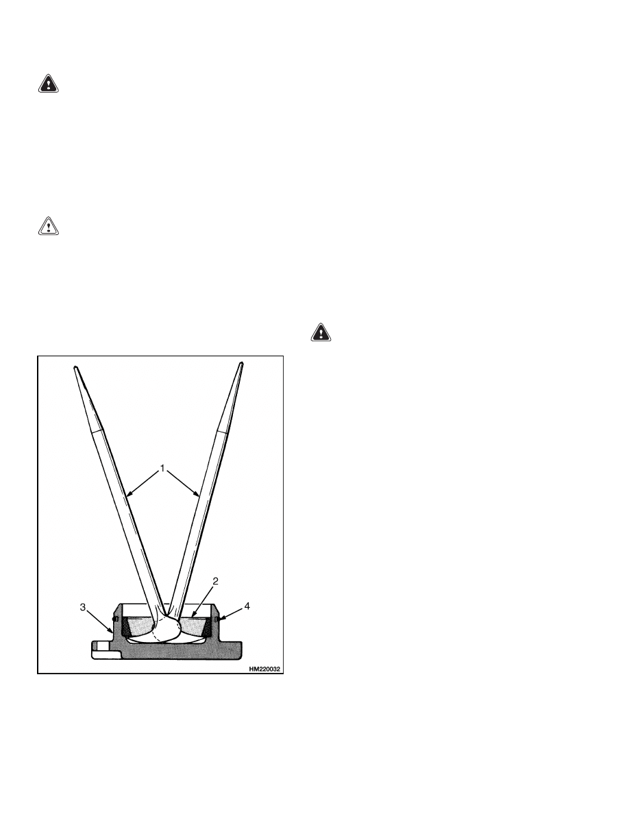
Remove the grease cap from the spindle. See Fig-
ure 1. Remove the capscrews from the bearing
cap and shims. If damaged, remove the bearing
cup from the bearing cap. See Figure 2.
1.
PRY BAR
2.
BEARING CUP
3.
BEARING CAP
4.
O-RING
Figure 2. Bearing Cup Removal
3.
Tilt the spindle and lift the spindle from the axle.
If the bearing must be replaced, remove the bear-
ing and seals from the spindle. Note the position
of seals during removal to aid in installation. If
the wear sleeve and the bearing cup are dam-
aged, remove them from the axle frame.
4.
Repeat the procedure for the other spindle.
CLEAN
WARNING
Cleaning solvents can be flammable and toxic
and can cause skin irritation.
When using
cleaning solvents, always follow the recom-
mendations of the manufacturer.
Clean all parts in solvent. Make sure the bearings
are clean and dry.
INSPECT
Inspect all parts and replace any parts that are worn
or damaged.
ASSEMBLE AND INSTALL
1.
Install new seals on the spindle as noted during
removal. Lubricate the seals with grease. See
Figure 1.
2.
Pack the bearings with grease. If removed, press
new bearing cups into steering axle frame and
bearing cap. If removed, install the wear sleeve
in the steering axle frame. If removed, install
bearing cones into the axle frame and bearing
cap.
3.
Install the grease cap on the top of the steering
axle. Use a sealant between the grease cap and
the steering axle.
4.
Install the spindle in the steering axle and adjust
the bearings as follows:
4

1600 SRM 733
Steering Cylinder Repair
a. Install the bearing cap without the O-ring.
Measure the clearance between the bearing
cap and the axle.
b. Remove the bearing cap and install enough
shims to give a preload of 0.00 to 0.127 mm
(0.000 to 0.005 in.).
The spindle bearings
must have no clearance.
c.
Install the O-ring on the bearing cap. Install
the bearing cap and capscrews. Tighten the
capscrews to 45 to 50 N•m (33 to 37 lbf ft).
5.
Install the tie rod as described in the procedures
for the Tie Rods Repair.
6.
Repeat the procedure for the other spindle.
Tie Rods Repair
REMOVE
1.
Remove snap ring at top of retaining pin on steer-
ing cylinder. See Figure 1. Push pin from steer-
ing cylinder.
2.
Remove snap ring at top of retaining pin on spin-
dle arm. Push pin from spindle arm.
3.
Remove tie rods from axle.
4.
Repeat for other tie rod.
CLEAN
WARNING
Cleaning solvents can be flammable and toxic
and can cause skin irritation.
When using
cleaning solvents, always follow the recom-
mendations of the manufacturer.
Clean all parts except ends of tie rods in solvent.
Make sure bearings are clean.
INSPECT
Inspect all parts and replace any parts that are worn
or damaged.
INSTALL
1.
Position tie rod to spindle arm and steering cylin-
der. See Figure 1.
2.
Install retaining pins and snap rings.
Steering Cylinder Repair
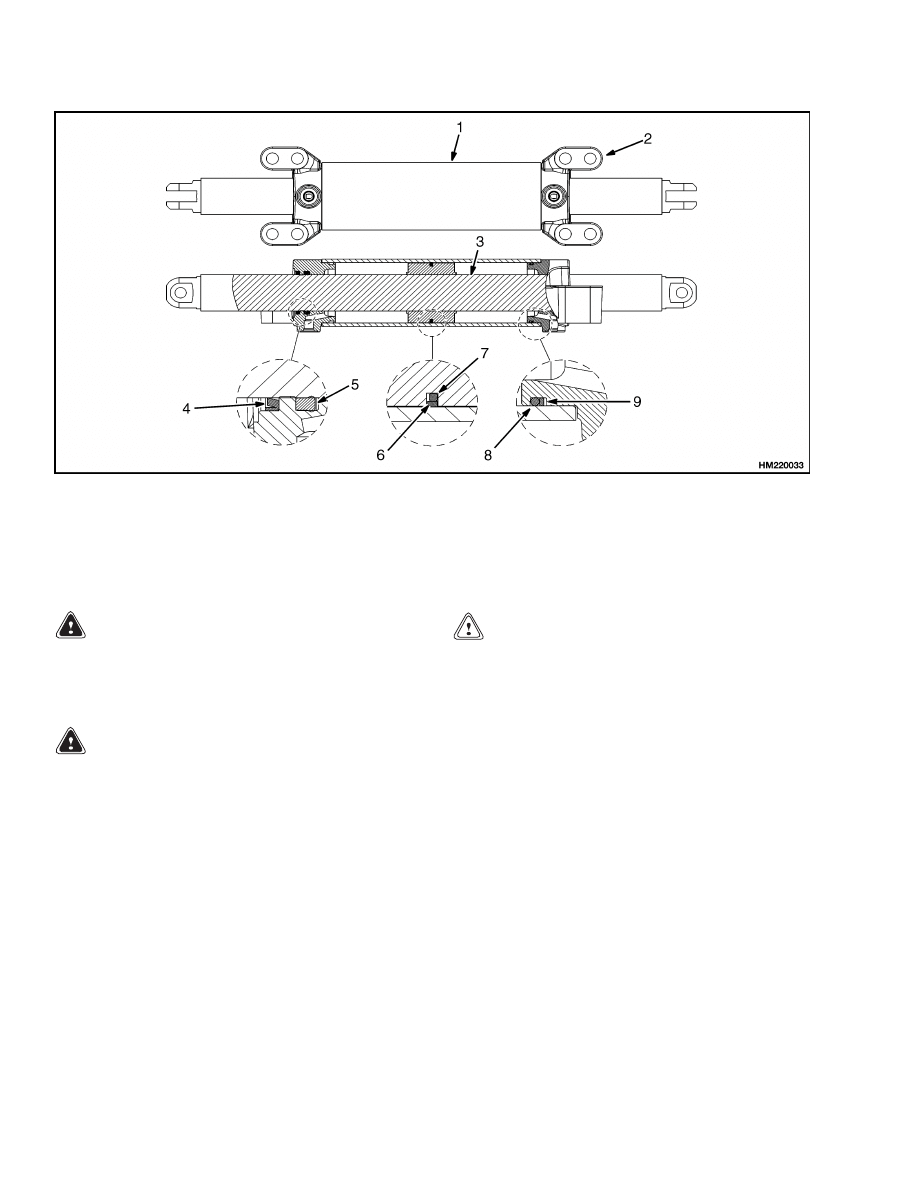
REMOVE AND DISASSEMBLE
NOTE:
The end caps of the steering cylinder are held
in the shell by the cylinder mount capscrews. To pre-
vent oil leaks at the caps, hold the caps on the shell
during removal. See Figure 1 and Figure 3.
1.
Disconnect the hydraulic lines at the steering
cylinder. Install plugs in the fittings on the cylin-
der and put caps on the hydraulic lines.
2.
Disconnect the tie rods as described in the proce-
dures for the Tie Rods Repair.
3.
Remove the capscrews and washers that fasten
the cylinder to the axle frame. Hold the end caps
on the shell and remove the steering cylinder.
4.
Hold the end of the steering cylinder over a drain
pan. Remove the cap for the hydraulic fitting
from each end cap. Push the rod toward the end
of the shell that is over the drain pan. Oil will
drain from the cylinder. Repeat the procedure for
the other end.
5.
Carefully slide one end cap from the shell. Care-
fully pull the rod from the shell. Keep the rod in
the center of the shell during removal. Remove
the end cap from the rod. Remove the other end
cap from the shell. Remove and discard all seals,
wipers, and O-rings.
5
Steering Cylinder Repair
1600 SRM 733
1.
CYLINDER SHELL
2.
END CAP
3.
ROD
4.
WIPER
5.
SEAL
6.
PISTON SEAL RING
7.
QUAD RING
8.
O-RING
9.
BACKUP RING
Figure 3. Steering Cylinder
CLEAN AND INSPECT
WARNING
Cleaning solvents can be flammable and toxic
and can cause skin irritation.
When using
cleaning solvents, always follow the recom-
mendations of the manufacturer.
WARNING
Compressed air can move particles so that they
cause injury to the user or to other personnel.
Make sure that the path of the compressed air
is away from all personnel.
Wear protective
goggles or a face shield to prevent injury to the
eyes.
1.
Clean all parts in solvent. Use compressed air to
dry the parts.
2.
Inspect the piston rod for grooves or damage. Re-
move small scratches with fine emery cloth. In-
spect the cylinder bore for damage. Inspect the
mounts for cracks.
ASSEMBLE AND INSTALL
CAUTION
Do not damage the O-rings, seals, or wipers
during installation.
1.
Install the O-rings, seals, and wipers. See Fig-
ure 1 and Figure 3.
2.
Lubricate the O-rings, seals, and wipers with
O-ring lubricant and carefully install one end cap
on the rod.
3.
Carefully slide the rod into the shell. Keep the
rod in the center of the shell during installation.
Carefully slide the end cap into the shell. Care-
fully install the other end cap on the rod and
shell. Put caps on the hydraulic fittings of the
end caps.
4.
Hold the end caps and install the cylinder on
the axle frame using the capscrews and washers.
Make sure the end caps are fully engaged with
the shell, then tighten the capscrews to 245 to
270 N•m (181 to 200 lbf ft).
5.
Install the tie rods as described in the procedures
for the Tie Rods Repair.
6

1600 SRM 733
Troubleshooting
6.
Remove the plugs and caps and connect the hy-
draulic lines to the steering cylinder. Start the
engine and operate the steering system to re-
move the air from the cylinders and the system.
Turn the steering wheel several times from one
stop to the other.
Troubleshooting
PROBLEM
POSSIBLE CAUSE
PROCEDURE OR ACTION
The steer wheels do not move
when the steering wheel is
turned.
The oil level is low or there is no oil
in the tank.
Fill tank. Check for leaks.
The steering control unit is dam-
aged.
Repair or install new control unit.
No oil flow from the steering control
unit to the steering cylinder.
Repair or install new components.
Check for leaks.
Slow or difficult steering.
Relief valve for the steering system
needs adjustment.
Adjust or install new relief valve.
Low oil pressure from the hydraulic
pump.
Check for restrictions.
Seal in the steering cylinder has a
leak.
Install new seal.
Steering control unit is worn or has
damage.
Repair or install new control unit.
Steering wheel turns the
tires in the wrong direction.
The hydraulic lines are not con-
nected correctly at the steering
cylinder or at the steering control
unit.
Connect lines properly. Remove air
from system.
Steering
function
contin-
ues after the steering wheel
stops.
The steering control unit was assem-
bled wrong or has damage.
Repair or install new control unit.
There is air in the steering
system.
The oil level in the tank is low.
Add hydraulic oil as necessary.
Air was not removed after repair to
the hydraulic or steering system.
Remove air from system.
The hydraulic pump has an air leak
at the inlet.
Check for leaks.
7

NOTES
____________________________________________________________
____________________________________________________________
____________________________________________________________
____________________________________________________________
____________________________________________________________
____________________________________________________________
____________________________________________________________
____________________________________________________________
____________________________________________________________
____________________________________________________________
____________________________________________________________
____________________________________________________________
____________________________________________________________
____________________________________________________________
____________________________________________________________
____________________________________________________________
____________________________________________________________
____________________________________________________________
____________________________________________________________
____________________________________________________________
8


TECHNICAL PUBLICATIONS
1600 SRM 733
9/03 (8/99) Printed in U.S.A.
Document Outline
- toc
Wyszukiwarka
Podobne podstrony:
897993 1600SRM0671 (09 2003) UK EN
897392 1600SRM0451 (09 2003) UK EN
1494140 1600SRM0936 (09 2003) UK EN
1494953 1400SRM0944 (09 2003) UK EN
897394 1900SRM0453 (09 2003) UK EN
1466241 1600SRM0732 (10 2003) UK EN
1498445 1400SRM0945 (09 2003) UK EN
1510463 1400SRM0984 (09 2003) UK EN
897987 1800SRM0659 (09 2003) UK EN
1494955 2000SRM0943 (09 2003) UK EN
897110 1900SRM0328 (09 2003) UK EN
897391 1400SRM0450 (09 2003) UK EN
910073 1400SRM0049 (09 2003) UK EN
1466247 1400SRM0731 (09 2003) UK EN
1466223 1900SRM0753 (09 2003) UK EN
więcej podobnych podstron