HYDRAULIC GEAR
PUMP
H3.50-5.50XM (H70-120XM) [K005, L005]
PART NO. 1466223
1900 SRM 753

SAFETY PRECAUTIONS
MAINTENANCE AND REPAIR
• When lifting parts or assemblies, make sure all slings, chains, or cables are correctly
fastened, and that the load being lifted is balanced. Make sure the crane, cables, and
chains have the capacity to support the weight of the load.
• Do not lift heavy parts by hand, use a lifting mechanism.
• Wear safety glasses.
• DISCONNECT THE BATTERY CONNECTOR before doing any maintenance or repair
on electric lift trucks.
• Disconnect the battery ground cable on internal combustion lift trucks.
• Always use correct blocks to prevent the unit from rolling or falling. See HOW TO PUT
THE LIFT TRUCK ON BLOCKS in the Operating Manual or the Periodic Mainte-
nance section.
• Keep the unit clean and the working area clean and orderly.
• Use the correct tools for the job.
• Keep the tools clean and in good condition.
• Always use HYSTER APPROVED parts when making repairs. Replacement parts
must meet or exceed the specifications of the original equipment manufacturer.
• Make sure all nuts, bolts, snap rings, and other fastening devices are removed before
using force to remove parts.
• Always fasten a DO NOT OPERATE tag to the controls of the unit when making repairs,
or if the unit needs repairs.
• Be sure to follow the WARNING and CAUTION notes in the instructions.
• Gasoline, Liquid Petroleum Gas (LPG), Compressed Natural Gas (CNG), and Diesel fuel
are flammable. Be sure to follow the necessary safety precautions when handling these
fuels and when working on these fuel systems.
• Batteries generate flammable gas when they are being charged. Keep fire and sparks
away from the area. Make sure the area is well ventilated.
NOTE:
The following symbols and words indicate safety information in this
manual:
WARNING
Indicates a condition that can cause immediate death or injury!
CAUTION
Indicates a condition that can cause property damage!

Hydraulic Gear Pump
Table of Contents
TABLE OF CONTENTS
General ...............................................................................................................................................................
Description .........................................................................................................................................................
Operation............................................................................................................................................................
Hydraulic Gear Pump Repair............................................................................................................................
Remove ...........................................................................................................................................................
Disassemble ...................................................................................................................................................
Clean ..............................................................................................................................................................
Inspect ............................................................................................................................................................
Assemble ........................................................................................................................................................
Install .............................................................................................................................................................
Pump Output Check ..........................................................................................................................................
Method No. 1 .................................................................................................................................................
Method No. 2 .................................................................................................................................................
Hydraulic System Air Check .............................................................................................................................
Troubleshooting..................................................................................................................................................
This section is for the following models:
H3.50-5.50XM (H70-120XM) [K005, L005]
©2003 HYSTER COMPANY
i

"THE
QUALITY
KEEPERS"
HYSTER
APPROVED
PARTS
1900 SRM 753
Operation
General
This section has the description, repair, and troubleshooting procedures for the hydraulic gear pump.
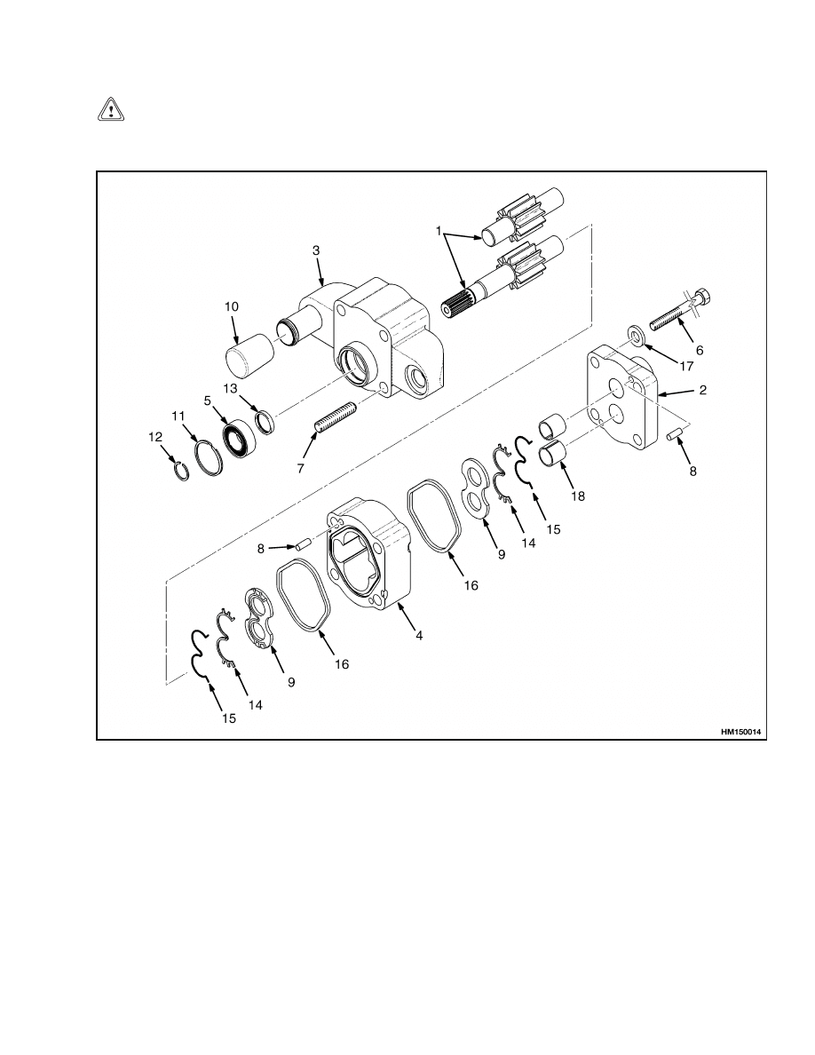
Description
The gear pump has several sections with a single
set (single stage) of gears. See Figure 2. The pump
has two covers and the gear housing with the gears.
Seals are used to prevent leaks between the sections.
The inlet and outlet ports are on the input shaft end
cover. The input shaft is splined to a fan pulley. The
fan pulley is connected to a drive shaft that is driven
by the engine crankshaft.
The gear pump has devices that keep the thrust
clearance at a minimum when the pressure in-
creases.
When the pressure is low, the clearance
increases to prevent wear. To prevent leakage when
the pressure is high, the oil from the outlet side of
the pump is transferred to a wear plate.
The oil
pushes the wear plate against the gears.
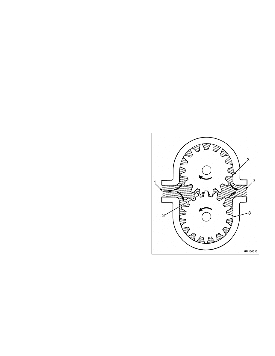
Operation
The gear pump has gears with teeth that engage in
the center of the pump. When the input shaft is
turned, the drive gear turns the driven gear. See Fig-
ure 1. The oil in the inlet chamber is moved out from
the center by the teeth of rotating gears. The oil be-
tween the teeth is moved around the pumping cham-
ber to the outlet chamber. The oil is pushed from the
outlet chamber by the gear teeth that are beginning
to engage.
The gears and bearings are lubricated by oil from the
outlet side of the pump. A small amount of oil flows
past the gears and into the bearings and front seal
cavity.
1.
INLET
2.
OUTLET
3.
SEAL MADE BY
GEAR TEETH
Figure 1. Gear Pump Operation
1
Hydraulic Gear Pump Repair
1900 SRM 753
Hydraulic Gear Pump Repair
REMOVE
WARNING
Make sure the carriage is lowered before dis-
connecting any parts of the hydraulic system.
NOTE:
Worn or damaged seals are the most common
cause of pump repair. The pump bearings, gears, and
shafts also wear. Many service persons do not re-
pair a worn pump because the cost of repairs can be
greater than the cost of a new pump. The seals can
be replaced in the hydraulic pump. If the pump is to
be rebuilt, the following procedures apply.
1.
Remove the pump drive shaft, fan belt, and pul-
ley as described in the section Cooling System
700 SRM 740.
2.
Remove the breather from the hydraulic tank
and install a plug. This action prevents the tank
from draining too fast when the inlet line is dis-
connected.
3.
Disconnect the hoses from the pump. Install caps
and plugs in the hoses and the pump. Be careful
so that the inlet hose is not damaged during re-
moval.
4.
Remove the nuts and washers holding the pump
to the fan mount bracket.
5.
Remove the pump from the lift truck.
6.
Remove the plate, isolators, and hose insulators
used for mounting of the pump.
DISASSEMBLE
1.
Carefully clean the outside of the pump.
See
Figure 2. Before disassembling the pump, make
alignment marks on all the housings.
2.
Place the pump in a vise with the drive shaft
pointing down. Make sure the vise does not hold
the pump too tight to cause distortion of the
pump body.
NOTE:
The position of the seals is important. The
holes in the seals must be aligned with the oil pas-
sages in the housing sections. The oil passage for the
thrust plates is in the outlet chamber.
NOTE:
Make sure that you make careful notes of the
location and orientation of the parts and seals during
disassembly. Some of the parts are similar, but not
exactly the same and it can be difficult to make an
identification if they are mixed.
3.
Remove the capscrews that hold the housings to-
gether. Remove the port end cover. Do not dam-
age the machined surfaces. Do not remove the
dowel pins that remain in the port end cover or
gear housing.
4.
Make a note of the positions of the thrust plate,
channel seal, and gasket seal. Remove the thrust
plate. Remove and discard the channel seal and
gasket seal.
5.
Remove the drive and driven gears. Keep gears
together as a set. Remove the gear housing. Do
not damage the machined surfaces.
6.
Make a note of the positions of the thrust plate,
channel seal, and gasket seal. Remove the thrust
plate. Remove and discard the channel seal and
gasket seal.
7.
Place the shaft end cover in a vise with the
mounting face up. Remove the retaining ring
and snap ring. Remove the bearing with a bear-
ing puller. Remove and discard the seal.
8.
Check all plugs to be sure they are tightly in
place. Replacement is necessary only if parts are
damaged. Remove with screwdriver.
9.
Check all bushings for wear or damage. If neces-
sary, remove bushings using a bushing puller.
CLEAN
WARNING
Cleaning solvents can be flammable and toxic
and can cause skin irritation.
When using
cleaning solvents, always follow the solvent
manufacturer’s recommended safety precau-
tions.
WARNING
Compressed air can move particles so that they
cause injury to the user or to other personnel.
Make sure that the path of the compressed air
is away from all personnel.
Wear protective
goggles or a face shield to prevent injury to the
eyes.
2
1900 SRM 753
Hydraulic Gear Pump Repair
CAUTION
Any dirt that enters the hydraulic system can
cause damage to the parts.
Clean all parts of the pump with solvent. Use com-
pressed air and a clean, lintless cloth to dry the parts.
Make sure the work area and tools are very clean.
1.
GEAR SET
2.
PORT END COVER
3.
SHAFT END COVER
4.
GEAR HOUSING
5.
BALL BEARING
6.
CAPSCREW
7.
STUD
8.
DOWEL PIN
9.
THRUST PLATE
10. INTAKE PORT COVER
11. SNAP RING
12. RETAINING RING
13. LIP SEAL
14. CHANNEL SEAL
15. CHANNEL SEAL BACKUP
16. GASKET SEAL
17. WASHER
18. BUSHING
Figure 2. Gear Pump Parts
3

Hydraulic Gear Pump Repair
1900 SRM 753
INSPECT
1.
Inspect the gears for any scoring, grooving, or
burring. Any scoring on the gear hubs requires
replacement. Any scoring, grooving, or burring
of outside diameter or surfaces of gear teeth also
requires replacement.
2.
If the gear shafts have grooves or are worn in
the seal area or the drive coupling area more
than 0.05 mm (0.002 in.), they must be replaced.
Wear in the seal area indicates oil contamination.
Wear or damage to splines, keys, or keyways re-
quires replacement.
NOTE:
Some pump bodies will show gear marks
where the gears rotate because of the small clear-
ances between the parts. These gear marks do not
indicate a worn or damaged pump unless the pump
will not supply the volume and pressure shown in
the specifications.
3.
Inspect the gear housing for wear or grooves.
Most wear occurs on the inlet or low pressure
side of the gear chamber. If the gear housing
is worn, inspect the bearings for wear. If the
system pressure is too high, the gear housings
will wear quickly. Grooves in the gear chamber
indicate dirt is in the oil.
Small holes in the
outlet side of the gear chamber indicate that
cavitation has occurred. To check, put a straight
edge across the inlet side of the gear chamber.
If a 0.18 mm (0.007 in.)
thickness gauge fits
between the straight edge and the housing, the
gear housing must be replaced.
If the surfaces of the gear chamber or gear teeth
have blue marks, the pump has been too hot.
Heat damage in the pump can be caused by hot
oil or lack of oil. Check the front seal surface
to see if air was entering the pump through the
front seal. Make sure the oil is the correct viscos-
ity. The wrong viscosity oil can increase leakage
within the pump. Leakage inside the pump in-
creases the oil temperature.
4.
Check the thrust plates for wear or grooves.
If a thrust plate is worn more than 0.05 mm
(0.002 in.), it must be replaced.
Replace the
thrust plate if it has grooves or holes. Dirty oil
causes the thrust plate to wear near where the
gears engage. Small holes on the outlet side of
the thrust plate is caused by cavitation. Lack
of oil can also cause small holes in the thrust
plates.
If the color of the thrust plates has
changed, the pump has been too hot.
5.
Inspect all the machined surfaces for scratches
or damage. Remove with emery cloth any metal
that is above the flat surface. Check the surfaces
with a straight edge. Inspect the grooves for the
seals for dirt or scratches.
6.
Inspect the bearings for wear or damage. Re-
place the bearings if there are any small holes
on the bearing surface. Replace the bushing if it
is not round.
7.
Look for damage on the seals. Replace all the
seals and O-rings, even if they are in good condi-
tion. Look for cuts or changes in shape that can
cause damage. Find out what damage caused the
pump to fail. A damaged seal for the thrust plate
can cause the shaft seal to leak. A damaged shaft
seal can cause air to enter the hydraulic system.
CAUTION
Do not permit dirty oil to enter the gear pump.
8.
If any parts of the pump have damage from dirt
in the oil, inspect the hydraulic tank. Drain the
tank, clean the screen and tank, and replace the
filter.
9.
Inspect the inlet hose to the gear pump. Use
a lamp to look inside the hose. Look for pieces
of the rubber that are separating from the hose.
Inspect the hose for restrictions at the bends.
Check for loose fittings or damaged O-rings.
ASSEMBLE
1.
Lubricate all parts with hydraulic oil before they
are installed into the pump. See Figure 2.
4
1900 SRM 753
Hydraulic Gear Pump Repair
WARNING
Cleaning solvents can be flammable and toxic
and can cause skin irritation.
When using
cleaning solvents, always follow the solvent
manufacturer’s recommended safety precau-
tions.
WARNING
Compressed air can move particles so that they
cause injury to the user or to other personnel.
Make sure that the path of the compressed air
is away from all personnel.
Wear protective
goggles or a face shield to prevent injury to the
eyes.
CAUTION
Make sure no dirt enters the pump during as-
sembly.
2.
Stone all machined surfaces with a medium
carborundum stone before assembly. If bushings
have been removed, deburr the bushing bores
with emery cloth. Clean parts with solvent and
dry with air and a clean lintless cloth before
starting assembly.
NOTE:
Install bushings for the drive gear bores with
the groove to the top of the unit. Install bushings for
the driven gear bores with the groove to the bottom.
See Figure 2.
3.
Press bushing into bores one at a time with a spe-
cial installation tool and a press. Bushings must
be flush with the casting face. Repeat Step 2.
4.
If new plugs are to be installed, coat the threads
with thread sealant and screw in tightly. Stake
plugs with a prick punch at both ends of screw-
driver slot and around edges. Peen edge of hole.
5.
Put Loctite 290
®
sealant around the outside of
the front seal. With the metal side of the seal up,
press it into the mounting flange side of the shaft
end cover until flush with the recess. Make sure
the seal is installed straight. Install the bearing
into its recess. This is a light press fit. It may be
necessary to lightly tap the bearing into the bore.
Install the snap ring and retaining ring.
6.
Grease the new gasket seals and install them
into the grooves in both sides of the gear hous-
ing. Place the gear housing over the shaft end
cover and dowels. Tap it with a soft hammer un-
til it rests tightly against the shaft end cover. Do
not pinch the gasket seal. Assemble the channel
seals into the grooves of the thrust plates with
the flat side facing away from the thrust plate.
Install the thrust plate with the channel seal fac-
ing the shaft end cover through gear housing.
The relief groove in the plate should face the out-
let side of the pump.
7.
Slide the driven gear through the gear housing
and into the bushing in the shaft end cover.
Lightly grease the drive shaft and slide through
the shaft end cover with a twisting motion until
the integral gear rests against the thrust plate.
Do not damage the shaft seal.
8.
Install the thrust plate with seal over gear jour-
nals and into the housing bore. The flat side of
the seal should face up with the relief groove fac-
ing the outlet side of the pump.
9.
Install the port end cover over the gear journals.
Align the dowels with the holes in the gear hous-
ing. Use a plastic hammer to join the sections.
Apply a small mount of Loctite 290
®
sealant to
the threads of the capscrews. Install the cap-
screws or studs and tighten with your fingers.
Rotate the drive shaft to make sure the pump
is assembled correctly. Tighten the capscrews to
272 N•m (201 lbf ft) using an X sequence.
INSTALL
NOTE:
Always install a new filter when repairs are
made to the hydraulic system. Drain and replace the
hydraulic oil if the oil is dirty or burned.
1.
Position the hose insulators, isolators, and plate
used for mounting the pump.
2.
Install the pump in the lift truck.
3.
Install the washers and nuts that hold the pump
to the fan mount bracket and tighten to 27 N•m
(20 lbf ft).
CAUTION
Before connecting any lines to the pump, fill all
ports with clean oil to provide initial lubrica-
tion.
4.
Remove the caps and plugs from the pump and
hoses. Connect the hoses to the pump.
5
Pump Output Check
1900 SRM 753
5.
Remove the plug from the breather on the hy-
draulic tank. Install the breather. Fill the tank
with clean hydraulic oil.
CAUTION
Do not permit hot oil to enter a cold pump. Do
not operate any valve until the pump has run
for two minutes at low pressure and low speed.
6.
Operate the pump at least two minutes at no load
and at engine idle. The unit should run free and
not develop an excessive amount of heat.
7.
If the pump operates properly, speed and pres-
sure can be increased to normal operating set-
tings. Reset the main relief valve to its proper
setting while the pump is running at maximum
operating engine speed.
See Capacities and
Specifications 8000 SRM 738 for proper set-
tings.
8.
Install the pump drive shaft, fan belt, and pulley
as described in the section Cooling System 700
SRM 740.
Pump Output Check
Two methods are given for checking the volume of
flow from the hydraulic pump. The first method uses
a flow meter, a pressure gauge, and a needle valve.
The second method uses a needle valve, a pressure
gauge, a container, and a timer.
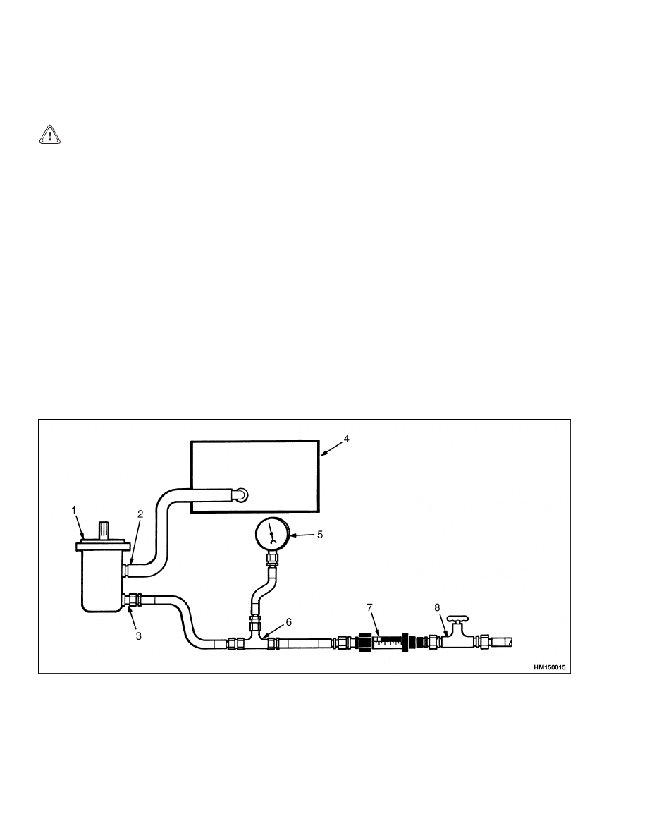
METHOD NO. 1
1.
If the flow meter is available, install the flow me-
ter between a needle valve and the outlet port
of the pump. See Figure 3. The pressure gauge
must be between the needle valve and the pump.
Make a separate check for each system if the
pump is a tandem or if a flow regulator is part
of the pump. When the hydraulic oil is at oper-
ating temperature, run the engine at 2200 rpm
with no load on the hydraulic system. Note the
reading of the flow meter. Compare the output
rate of the pump with the specification found in
Capacities and Specifications 8000 SRM 738.
1.
HYDRAULIC PUMP
2.
INLET PORT
3.
OUTLET PORT
4.
HYDRAULIC TANK
5.
PRESSURE GAUGE
6.
TEE FITTING
7.
FLOW METER
8.
NEEDLE VALVE
Figure 3. Hydraulic Pump Output Check With Flow Meter
6
1900 SRM 753
Pump Output Check
2.
Run the engine at the high limit. Slowly close the
needle valve until the gauge indicates a pressure
just below the specification for the relief valve
setting. The pump output at the high or pres-
sure must be within 25% of the output with no
load. If the output at high pressure is less than
75% of the low pressure output, the pump has a
problem.
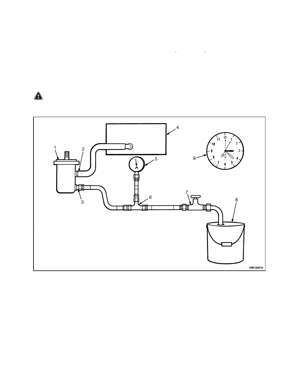
METHOD NO. 2
WARNING
Hydraulic oil can be hot. Do not touch the oil
during the tests.
1.
Another method of checking the pump output is
to measure the amount of oil moved in a given
amount of time. Run the engine until the oil is 50
to 65 C (120 to 150 F). Disconnect the line from
the outlet port of the pump. Install a 0 to 20 MPa
(0 to 3000 psi) pressure gauge on a tee fitting
connected to a hose from the outlet port. Install
the needle valve on the end of the hose. Connect
another hose to the needle valve. Put the other
end of the hose in a container with an 18 liter
(5 gal) capacity. Make sure the reservoir is full.
See Figure 4.
1.
HYDRAULIC PUMP
2.
INLET PORT
3.
OUTLET PORT
4.
HYDRAULIC TANK
5.
PRESSURE GAUGE
6.
TEE FITTING
7.
NEEDLE VALVE
8.
CONTAINER
9.
TIMER
Figure 4. Hydraulic Pump Output Check
7

Troubleshooting
1900 SRM 753
CAUTION
This test must be done quickly to prevent the
hydraulic tank from becoming empty. Do not
operate the engine when there is no oil in the
hydraulic tank.
2.
The needle valve must be fully open. Start the
engine and run the engine at its governed rpm
for 5 seconds. Stop the engine. Measure the vol-
ume of oil that entered the container in 5 sec-
onds. Multiply the quantity in the container by
12 to find the output per minute. Compare the
pump output rate with the specifications found
in Capacities and Specifications 8000 SRM
738. The pump output rate must be within 20%
of the specifications.
3.
Start the engine and run the engine at its gov-
erned rpm.
Close the needle valve until the
pressure increases to just below the relief valve
setting. Measure the volume of fluid the pump
moves in 5 seconds. Compare this quantity with
the results from the test of the pump output at
low pressure. The output of the pump at high
pressure must be within 25% of the volume of oil
flow at low pressure.
Hydraulic System Air Check
If the pump makes noise or does not move the correct
amount of oil, check for air in the system. Run the
engine until the oil is warm. Remove the filter and
look into the tank. If there are bubbles in the oil, air
is in the hydraulic system. The most common place of
entry of the air is in the inlet hose to the pump. Check
for air leaks by pouring oil over the fittings and hose
when the engine is running. If the noise decreases,
the leak is in that area. See Troubleshooting for other
causes of air in the hydraulic system.
Troubleshooting
PROBLEM
POSSIBLE CAUSE
PROCEDURE OR ACTION
The pump makes more noise
than normal.
There is no oil or not enough oil in
the hydraulic tank.
Fill the tank to the correct level.
The hydraulic pump is worn or dam-
aged.
Repair or replace hydraulic pump.
Hydraulic pump drive arrangement
is damaged.
Repair pump drive.
Wrong type or grade of hydraulic oil
for the temperature or operation.
Check grade of hydraulic oil. Drain
tank, and fill with the correct speci-
fied oil if needed.
Screen in hydraulic tank has a re-
striction.
Clean or install new screen.
Air in the hydraulic system.
Check for leaks and remove air from
the system.
The pump is loose at the mount.
Tighten mounting nuts as required.
8

1900 SRM 753
Troubleshooting
PROBLEM
POSSIBLE CAUSE
PROCEDURE OR ACTION
Hydraulic pressure is below
specifications.
There is no oil or not enough oil in
the hydraulic tank.
Fill the tank to the correct level.
Relief valve(s) in the main control
valve is damaged or not adjusted
correctly.
Replace the relief valve.
Hydraulic pump is worn or damaged.
Repair or replace the hydraulic
pump.
Wrong type or grade of hydraulic oil
for the temperature or operation.
Check grade of hydraulic oil. Drain
tank, and fill with the correct speci-
fied oil if needed.
Air in the hydraulic system.
Check for leaks and remove air from
the system.
Screen in hydraulic tank has a re-
striction.
Clean or install new screen.
The pump wears faster than
normal.
There is no oil or not enough oil in
the hydraulic tank.
Fill the tank to the correct level.
Relief valve(s) in the main control
valve is damaged or not adjusted
correctly.
Replace the relief valve(s).
Wrong type or grade of hydraulic oil
for the temperature or operation.
Check grade of hydraulic oil. Drain
tank, and fill with the correct speci-
fied oil if needed.
Air in the hydraulic system.
Check for leaks and remove air from
the system.
Dirt in the hydraulic system.
Check. Drain and clean system. Fill
with new hydraulic oil.
Pump drive is not correctly aligned.
Check and align as necessary.
Pump is operating too hot.
Locate cause and make necessary
corrections.
Air in hydraulic system.
There is no oil or not enough oil in
the hydraulic tank.
Fill the tank to the correct level.
Pump seal is damaged.
Repair or replace hydraulic pump.
Pump housing capscrews are loose.
Tighten capscrews to correct torque.
9

Troubleshooting
1900 SRM 753
PROBLEM
POSSIBLE CAUSE
PROCEDURE OR ACTION
Air
in
hydraulic
system.
(Cont.)
Inlet hose has a leak or restriction.
Repair or replace hose.
Screen in hydraulic tank has a re-
striction.
Clean or replace screen.
Breather on hydraulic tank has a re-
striction.
Clean or replace breather.
Worn or damaged pump.
Repair or replace pump.
10


TECHNICAL PUBLICATIONS
1900 SRM 753
9/03 (8/99) Printed in United Kingdom
Document Outline
Wyszukiwarka
Podobne podstrony:
897394 1900SRM0453 (09 2003) UK EN
897110 1900SRM0328 (09 2003) UK EN
1494953 1400SRM0944 (09 2003) UK EN
1498445 1400SRM0945 (09 2003) UK EN
910092 1900SRM0098 (07 2003) UK EN
1510463 1400SRM0984 (09 2003) UK EN
897987 1800SRM0659 (09 2003) UK EN
1494955 2000SRM0943 (09 2003) UK EN
897121 1900SRM0339 (10 2003) UK EN
897993 1600SRM0671 (09 2003) UK EN
897391 1400SRM0450 (09 2003) UK EN
897392 1600SRM0451 (09 2003) UK EN
1466235 1600SRM0733 (09 2003) UK EN
910073 1400SRM0049 (09 2003) UK EN
1466247 1400SRM0731 (09 2003) UK EN
897113 8000SRM0331 (09 2003) UK EN
więcej podobnych podstron