HYDRAULIC SYSTEM
H6.00-7.00XL (H135-155XL,
H135-155XL
2
) [F006, G006]
PART NO. 897110
1900 SRM 328

SAFETY PRECAUTIONS
MAINTENANCE AND REPAIR
• When lifting parts or assemblies, make sure all slings, chains, or cables are correctly
fastened, and that the load being lifted is balanced. Make sure the crane, cables, and
chains have the capacity to support the weight of the load.
• Do not lift heavy parts by hand, use a lifting mechanism.
• Wear safety glasses.
• DISCONNECT THE BATTERY CONNECTOR before doing any maintenance or repair
on electric lift trucks.
• Disconnect the battery ground cable on internal combustion lift trucks.
• Always use correct blocks to prevent the unit from rolling or falling. See HOW TO PUT
THE LIFT TRUCK ON BLOCKS in the Operating Manual or the Periodic Mainte-
nance section.
• Keep the unit clean and the working area clean and orderly.
• Use the correct tools for the job.
• Keep the tools clean and in good condition.
• Always use HYSTER APPROVED parts when making repairs. Replacement parts
must meet or exceed the specifications of the original equipment manufacturer.
• Make sure all nuts, bolts, snap rings, and other fastening devices are removed before
using force to remove parts.
• Always fasten a DO NOT OPERATE tag to the controls of the unit when making repairs,
or if the unit needs repairs.
• Be sure to follow the WARNING and CAUTION notes in the instructions.
• Gasoline, Liquid Petroleum Gas (LPG), Compressed Natural Gas (CNG), and Diesel fuel
are flammable. Be sure to follow the necessary safety precautions when handling these
fuels and when working on these fuel systems.
• Batteries generate flammable gas when they are being charged. Keep fire and sparks
away from the area. Make sure the area is well ventilated.
NOTE:
The following symbols and words indicate safety information in this
manual:
WARNING
Indicates a condition that can cause immediate death or injury!
CAUTION
Indicates a condition that can cause property damage!

Hydraulic System
Table of Contents
TABLE OF CONTENTS
General ...............................................................................................................................................................
Description and Operation ................................................................................................................................
Hydraulic Pumps ...........................................................................................................................................
Main Control Valve........................................................................................................................................
Control Valve Lever .......................................................................................................................................
Steering Control Unit ....................................................................................................................................
Brake Valve ....................................................................................................................................................
Oil Clutch, H6.00-7.00XL (H135-155XL) (F006)..........................................................................................
Troubleshooting..................................................................................................................................................
This section is for the following models:
H6.00-7.00XL (H135-155XL,
H135-155XL
2
) [F006, G006]
©2003 HYSTER COMPANY
i

"THE
QUALITY
KEEPERS"
HYSTER
APPROVED
PARTS
1900 SRM 328
Description and Operation
General
This section has the description and operation of the complete hydraulic system. There are also brief descrip-
tions of the components of the hydraulic system. A troubleshooting guide for the hydraulic system is also
included.
Description and Operation
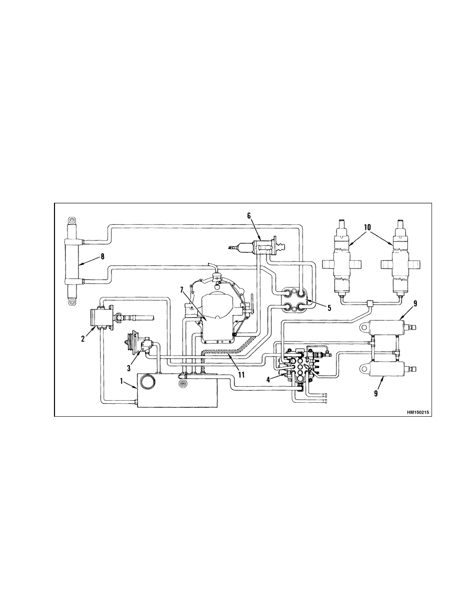
The hydraulic system includes the circuits for the
mast, steering system, brake system, and the oil
clutch. See Figure 1 and Figure 2. Two hydraulic
pumps supply the flow of oil for the components of
the hydraulic system.
The main hydraulic pump
(for the mast and attachments) is driven by a drive
shaft connected to the engine crankshaft pulley.
The hydraulic pump for the steering, brake, and
clutch systems is driven by the engine.
On GM
engine-equipped units, the steering pump is driven
by a belt and pulley arrangement.
On Perkins
diesel-equipped units, the pump is driven by the
timing gears. Both of the hydraulic pumps get their
oil supply from the hydraulic tank.
1.
HYDRAULIC TANK
2.
MAIN HYDRAULIC PUMP
3.
STEERING HYDRAULIC PUMP
4.
MAIN CONTROL VALVE
5.
STEERING CONTROL UNIT
6.
BRAKE VALVE
7.
OIL CLUTCH HOUSING
8.
STEERING CYLINDER
9.
TILT CYLINDERS
10. LIFT CYLINDERS
11. RETURN LINE (WITH POWERSHIFT
TRANSMISSION)
Figure 1. Hydraulic System Diagram
1
Description and Operation
1900 SRM 328
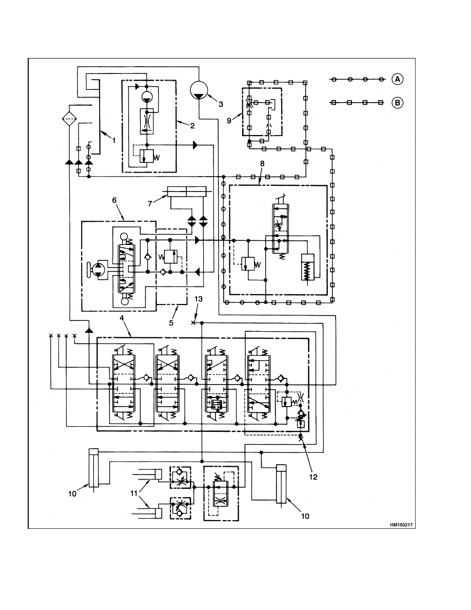
Figure 2. Hydraulic System Schematic
2
1900 SRM 328
Description and Operation
Legend for Figure 2
A. POWERSHIFT TRANSMISSION UNITS
B. MANUAL TRANSMISSION UNITS H6.00-7.00XL
(H135-155XL) (F006)
1.
HYDRAULIC TANK
2.
STEERING HYDRAULIC PUMP
3.
HYDRAULIC PUMP
4.
MAIN CONTROL VALVE
5.
MANIFOLD BLOCK
6.
STEERING CONTROL UNIT
7.
STEERING CYLINDER
8.
BRAKE VALVE
9.
OIL CLUTCH HOUSING
10. TILT CYLINDER
11. LIFT CYLINDER
12. LIFT SYSTEM CHECK PORT
13. CHECK PORT
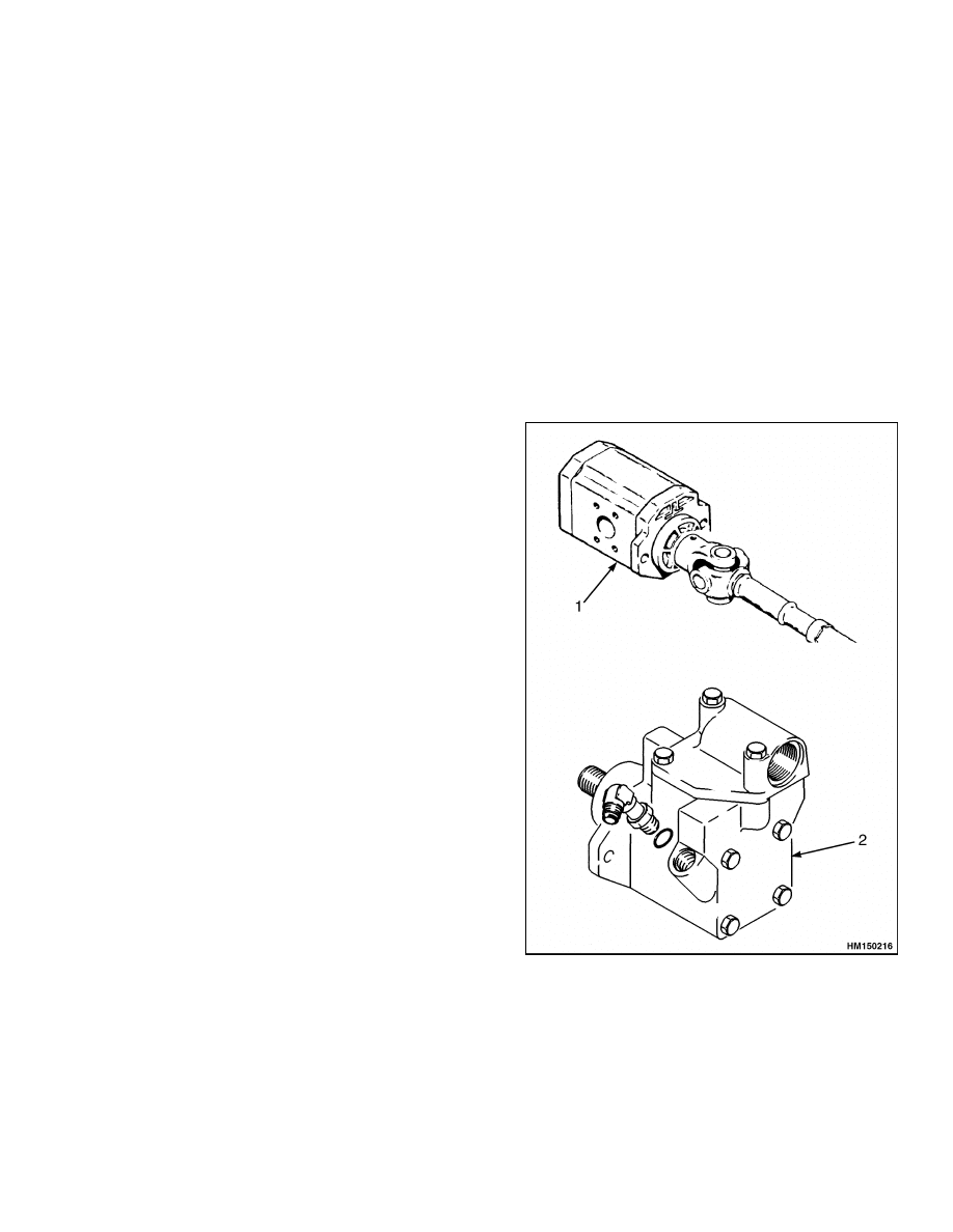
HYDRAULIC PUMPS
The main hydraulic pump is a gear pump and sup-
plies oil only to the main control valve. See Figure 3.
Oil that is not used by the mast or attachment cylin-
ders flows through the control valve and back to the
hydraulic tank.
In normal applications, the steering hydraulic pump
is a vane pump. In heavy duty applications, a gear
pump is used. The pump supplies oil first to the
steering control unit. Excess oil from the steering
control unit flows to the brake valve. From the brake
valve, the oil then flows to the oil clutch housing (if
equipped) and then back to the hydraulic tank. The
steering hydraulic pump has an internal relief valve
that is set at 11.7 to 12.4 MPa (1700 to 1800 psi).
MAIN CONTROL VALVE
The main control valve controls the lift, lower, tilt,
and attachment functions. The control valve receives
oil from the main hydraulic pump. Oil flow in the
main control valve goes first to the relief valve and
the lift spool. From the lift spool, oil goes to the tilt
spool and then the auxiliary spools. Oil that is not
used by one spool can be used by any of the following
spools. If one spool uses all of the oil, there is no flow
to the following spools.
The main relief valve for the system is set at
21.0 MPa (3050 psi). If the lift truck has attach-
ments, the control valve has a two-stage relief valve,
with the auxiliary relief pressure set at 15.5 MPa
(2250 psi). The two-stage relief valve uses a pilot line
from the lift spool to change its operation. When the
lift spool is in the Lift position, pressure is applied
through the pilot line to the top of the relief valve.
This additional pressure on the spool in the relief
valve causes the higher relief pressure for the lift
circuit.
The return oil from the main control valve flows into
the hydraulic tank and through the oil filter.
1.
MAIN HYDRAULIC PUMP
2.
STEERING HYDRAULIC PUMP (DIESEL
SHOWN)
Figure 3. Hydraulic Pumps
3
Description and Operation
1900 SRM 328
CONTROL VALVE LEVER
If the lever weldment bypasses the control valve
lever locks, use the following procedure:
Check to see if the selector pin has an overall width
of 23.8 mm (0.9 in.). If the pin width is greater than
23.8 mm (0.9 in.), grind the pin to the proper dimen-
sion.
Verify that there are two shims between the 2nd and
3rd function lever that measure 0.254 mm (0.010 in.)
and 0.508 mm (0.20 in.).
STEERING CONTROL UNIT
The steering control unit is a rotary valve that con-
trols the movement of the steering cylinder. The sup-
ply of oil for the unit comes from the steering hy-
draulic pump. The control unit has a minimum re-
striction to oil flow when the steering wheel is not
moved. The control unit has four ports. A manifold
block is installed on the steering control unit over the
four ports. The inlet port in the manifold block has
a check valve and a relief valve and is connected to
the hydraulic pump. The relief valve is set at 11.7 to
12.4 MPa (1700 to 1800 psi). Two of the ports are con-
nected to the steering cylinder. The port for the drain
circuit is connected to the inlet of the brake valve. All
of the oil that flows to the steering control unit flows
to the brake valve.
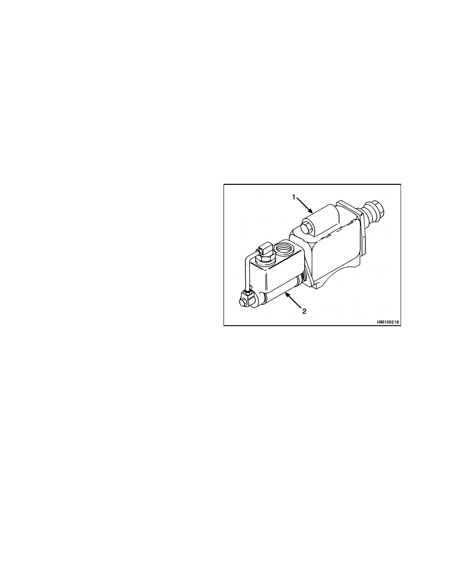
BRAKE VALVE
The brake system on this series of lift trucks uses a
hydraulic actuator (brake valve) to actuate the mas-
ter cylinder. See Figure 4. The operation of the brake
valve decreases the foot pressure necessary to ap-
ply the brakes. The oil pressure from the outlet of
the steering control unit is used to operate the brake
valve.
A relief valve in the brake valve is set at
1310 kPa (190 psi). On lift trucks with a powershift
transmission, oil from the brake valve goes to the hy-
draulic tank. On lift trucks with a manual transmis-
sion, oil from the brake valve goes to the oil clutch
housing.
1.
BRAKE VALVE
2.
MASTER CYLINDER
Figure 4. Brake Valve
4
1900 SRM 328
Troubleshooting
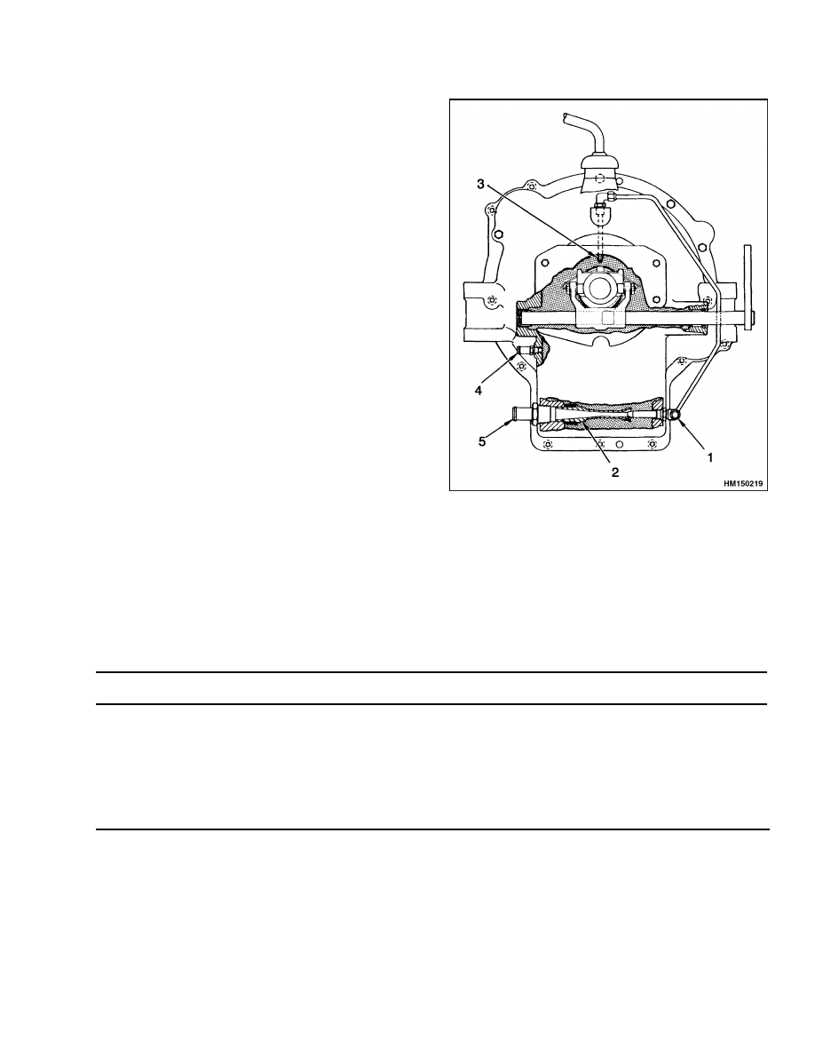
OIL CLUTCH, H6.00-7.00XL (H135-155XL)
(F006)
The oil supply for the oil clutch comes from the brake
valve. See Figure 5. At the clutch housing, the oil
goes to two fittings. One fitting supplies oil for cool-
ing the clutch disc. The other fitting supplies the oil
to operate the jet pump at the bottom of the clutch
housing. The jet pump removes the cooling oil from
the clutch housing and sends it back to the hydraulic
tank.
1.
SUPPLY LINE
2.
JET PUMP
3.
NOZZLE FOR
CLUTCH DISC
4.
DRAIN LINE
5.
RETURN LINE
Figure 5. Oil Clutch, H6.00-7.00XL
(H135-155XL) (F006)
Troubleshooting
PROBLEM
POSSIBLE CAUSE
PROCEDURE OR ACTION
Hydraulic functions will not
operate.
There is no oil or not enough oil in
the hydraulic tank.
Fill tank to correct level. Check for
leaks.
The hydraulic pump(s) are damaged.
Repair or replace hydraulic pump.
The hydraulic pump(s) are not con-
nected to the engine.
Connect hydraulic pumps.
5

Troubleshooting
1900 SRM 328
PROBLEM
POSSIBLE CAUSE
PROCEDURE OR ACTION
Hydraulic pressure is above
or below specifications.
Relief valve is damaged.
Replace relief valve.
Relief valve is not adjusted correctly.
Adjust relief valve.
Restriction in the return line(s).
Remove any restriction or replace re-
turn lines.
LIFT, LOWER, AND TILT CIRCUIT
Slow or no movement of
cylinder(s).
Pressure relief valve is damaged or
is not adjusted correctly.
Adjust or replace relief valve.
Large leaks between spool and bore.
Repair or replace control valve sec-
tion.
Spool not fully extended or retracted.
Check adjustment of control linkage.
Broken spring(s) for the spool(s).
Repair control valve.
The drive shaft for the hydraulic
pump is not connected.
Connect drive shaft for the hydraulic
pump.
Air is in the system.
Operate hydraulic system to remove
air. Check for leaks on inlet to hy-
draulic pump.
Load is greater than capacity of the
system.
Reduce load.
Restriction in the return line(s).
Remove any restriction or replace
lines.
Cylinder seals are damaged.
Replace seals.
Lift cylinders retract when
the spool is in the NEU-
TRAL position.
Oil leaks between spool and bore.
Repair or replace control valve sec-
tion.
Cylinder seals or check valves leak.
Replace seals.
Repair or replace
check valve.
Hydraulic line to cylinder(s) leak.
Repair or replace hydraulic lines.
6

1900 SRM 328
Troubleshooting
PROBLEM
POSSIBLE CAUSE
PROCEDURE OR ACTION
Tilt cylinders move forward
when the spool is in the
NEUTRAL position.
Tilt control spool inside tilt spool
does not work correctly.
Clean and repair or replace tilt spool
section.
Oil leaks between spool and bore.
Clean and repair or replace tilt spool
section.
Hydraulic lines leak.
Repair hydraulic lines.
Tilt cylinder seals leak.
Check and repair leaks.
Lift cylinders permit mast to
lower when spool is moved to
LIFT position.
Load check valve is damaged.
Check and repair or replace lift/lower
section of main control valve.
STEERING, BRAKE, AND OIL CLUTCH SYSTEM
There is no action when the
steering wheel is turned.
There is no oil or not enough oil in
the hydraulic tank.
Check and repair leaks.
Add hy-
draulic oil.
Hydraulic lines to the steering cylin-
der are damaged or have a restric-
tion.
Repair or replace hydraulic lines.
The drive belt for the steering pump
is not installed (GM engines).
Replace drive belt.
The drive gear for the hydraulic
pump is damaged or loose (Perkins
engine).
Repair or replace drive gear.
The relief valve in the manifold block
is not adjusted correctly.
Adjust or replace relief valve.
The steering control unit is dam-
aged.
Repair or replace steering control
unit.
There is air in the system.
Operate hydraulic system to remove
air. Check for leaks on inlet to hy-
draulic pump.
7

Troubleshooting
1900 SRM 328
PROBLEM
POSSIBLE CAUSE
PROCEDURE OR ACTION
The lift truck steers slowly,
or the steering wheel is hard
to turn.
There is a restriction in the hy-
draulic lines.
Remove any restrictions or replace
hydraulic lines.
The relief valve in the steering pump
is not adjusted correctly or is dam-
aged.
Adjust or replace relief valve.
The relief valve in the manifold block
is not correctly adjusted or is dam-
aged.
Adjust or replace relief valve.
The hydraulic pump is worn or dam-
aged.
Repair or replace pump.
The steering wheel turns the
wheels in the wrong direc-
tion.
The steering control unit is worn or
damaged.
Repair or replace steering control
unit.
The hydraulic lines at the steering
control unit or steering cylinder are
not connected correctly.
Check connections of hydraulic lines.
The brake valve does not op-
erate correctly.
The hydraulic line from the steering
does not operate correctly.
Remove any restriction or replace hy-
draulic line.
The hydraulic line from the brake
valve to the hydraulic tank has a
restriction.
Remove any restriction or replace hy-
draulic line.
There is no oil supply for the
oil clutch.
The hydraulic line, from the brake
valve for the oil clutch, has a restric-
tion or a leak.
Remove any restriction or replace hy-
draulic line.
The fittings or tubing on the clutch
housing have leaks or damage.
Tighten or replace fittings or tubing.
8


TECHNICAL PUBLICATIONS
1900 SRM 328
9/03 (3/97)(5/86) Printed in United Kingdom
Document Outline
- toc
Wyszukiwarka
Podobne podstrony:
897394 1900SRM0453 (09 2003) UK EN
1466223 1900SRM0753 (09 2003) UK EN
1494953 1400SRM0944 (09 2003) UK EN
1498445 1400SRM0945 (09 2003) UK EN
910092 1900SRM0098 (07 2003) UK EN
1510463 1400SRM0984 (09 2003) UK EN
897987 1800SRM0659 (09 2003) UK EN
1494955 2000SRM0943 (09 2003) UK EN
897121 1900SRM0339 (10 2003) UK EN
897993 1600SRM0671 (09 2003) UK EN
897391 1400SRM0450 (09 2003) UK EN
897392 1600SRM0451 (09 2003) UK EN
1466235 1600SRM0733 (09 2003) UK EN
910073 1400SRM0049 (09 2003) UK EN
1466247 1400SRM0731 (09 2003) UK EN
897113 8000SRM0331 (09 2003) UK EN
więcej podobnych podstron