DRIVE AXLE
S6.00-7.00XL (S135-155XL, S155XLS,
S135-155XL
2
) [B024, C024]
PART NO. 897391
1400 SRM 450

SAFETY PRECAUTIONS
MAINTENANCE AND REPAIR
• When lifting parts or assemblies, make sure all slings, chains, or cables are correctly
fastened, and that the load being lifted is balanced. Make sure the crane, cables, and
chains have the capacity to support the weight of the load.
• Do not lift heavy parts by hand, use a lifting mechanism.
• Wear safety glasses.
• DISCONNECT THE BATTERY CONNECTOR before doing any maintenance or repair
on electric lift trucks.
• Disconnect the battery ground cable on internal combustion lift trucks.
• Always use correct blocks to prevent the unit from rolling or falling. See HOW TO PUT
THE LIFT TRUCK ON BLOCKS in the Operating Manual or the Periodic Mainte-
nance section.
• Keep the unit clean and the working area clean and orderly.
• Use the correct tools for the job.
• Keep the tools clean and in good condition.
• Always use HYSTER APPROVED parts when making repairs. Replacement parts
must meet or exceed the specifications of the original equipment manufacturer.
• Make sure all nuts, bolts, snap rings, and other fastening devices are removed before
using force to remove parts.
• Always fasten a DO NOT OPERATE tag to the controls of the unit when making repairs,
or if the unit needs repairs.
• Be sure to follow the WARNING and CAUTION notes in the instructions.
• Gasoline, Liquid Petroleum Gas (LPG), Compressed Natural Gas (CNG), and Diesel fuel
are flammable. Be sure to follow the necessary safety precautions when handling these
fuels and when working on these fuel systems.
• Batteries generate flammable gas when they are being charged. Keep fire and sparks
away from the area. Make sure the area is well ventilated.
NOTE:
The following symbols and words indicate safety information in this
manual:
WARNING
Indicates a condition that can cause immediate death or injury!
CAUTION
Indicates a condition that can cause property damage!

Drive Axle
Table of Contents
TABLE OF CONTENTS
General ...............................................................................................................................................................
Description .........................................................................................................................................................
Drive Axle Repair...............................................................................................................................................
Remove ...........................................................................................................................................................
Units With Manual Transmission ............................................................................................................
Units With Powershift Transmission .......................................................................................................
Disassemble ...................................................................................................................................................
Clean ..............................................................................................................................................................
Inspect ............................................................................................................................................................
Assemble ........................................................................................................................................................
Install .............................................................................................................................................................
Units With Manual Transmission ............................................................................................................
Units With Powershift Transmission .......................................................................................................
Torque Specifications .........................................................................................................................................
Troubleshooting..................................................................................................................................................
This section is for the following models:
S6.00-7.00XL (S135-155XL, S155XLS, S135-155XL
2
) [B024, C024]
©2003 HYSTER COMPANY
i

"THE
QUALITY
KEEPERS"
HYSTER
APPROVED
PARTS
1400 SRM 450
Description
General
This section has the removal and disassembly pro-
cedures for the drive axle. The drive axle includes:
the axle housing, the axles, the differential, the ser-
vice brakes, and the wheel assemblies. Most of the
assemblies in the drive axle housing are covered by
other sections. The differential is part of the man-
ual transmission assembly on units with the manual
transmission. See the section Three-Speed Man-
ual Transmission 1300 SRM 335 for differential re-
pair. On units with the powershift transmission, see
the section Differential 1400 SRM 46 for differen-
tial repair. See the section Brake System 1800 SRM
452 to repair the service brake assemblies.
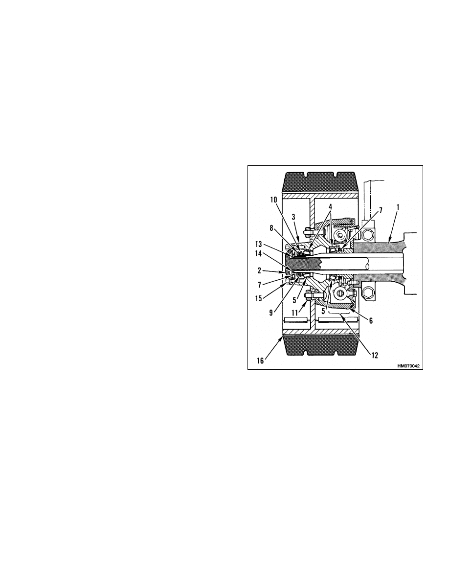
Description
This direct drive axle has a housing, two axle shafts,
and two hubs. The rotation of the differential turns
the axle shafts and the hubs. The hubs rotate on
tapered roller bearings. The brake drums and wheels
are installed on each hub. See Figure 1.
1.
AXLE HOUSING
2.
AXLE SHAFT
3.
HUB
4.
BEARING CUP
5.
BEARING CONE
6.
BRAKE DRUM
7.
SEAL
8.
LOCK NUT
9.
LOCKWASHER
10. ADJUSTMENT NUT
11. WHEEL NUT
12. BRAKE ASSEMBLY
13. WEAR SLEEVE
14. GASKET
15. TAPERED
CAPSCREW
16. WHEEL
Figure 1. Drive Axle
1

Drive Axle Repair
1400 SRM 450
Drive Axle Repair
REMOVE
Units With Manual Transmission
WARNING
The lift truck must be put on blocks for some
types of maintenance and repair. The removal
of the drive axle causes large changes in the
center of gravity. When the lift truck is put on
blocks, put additional blocks in the following
position:
Before removing the drive axle, put blocks
under the counterweight so the lift truck
cannot tip backward.
Put the lift truck on blocks only if the surface
is solid, even, and level. Make sure that any
blocks used to support the lift truck are solid,
one-piece units.
It is usually not necessary to remove the axle hous-
ing from the frame for repairs to the drive axle. If
necessary, the axle shafts can be removed without
removing the wheels and hubs. The axle housing is
normally removed as a unit with the manual trans-
mission.
The normal procedure is to remove the manual trans-
mission and the drive axle as an assembly. See the
section Three-Speed Manual Transmission 1300
SRM 335 to remove the drive axle.
Units With Powershift Transmission
Do the following procedure to remove the drive axle:
1.
Remove the floor plates. Disconnect the negative
cable from the battery.
2.
Remove the upright and carriage assembly as de-
scribed in the section Masts Description and
Repair 4000 SRM 329.
3.
Disconnect the brake lines at the wheel cylin-
ders. Disconnect the park brake cables at the
lever assembly.
4.
On units with a MONOTROL
®
pedal, remove the
rod that fits between the parking brake lever
and the switch on the cowl. Remove the parking
brake lever from the cowl. Remove the clamps
for the parking brake cables where they fasten
to the frame.
5.
Put blocks on both sides (front and back) of the
steering tires so the lift truck cannot move. Con-
nect a lifting device to the front of the frame of the
lift truck. Remove the four large capscrews that
hold the drive axle assembly to the frame. These
capscrews are tightened to 1040 N•m (768 lbf ft).
6.
Raise the lift truck frame just enough to allow the
drive axle to be removed. Make sure the parking
brake cables that are still attached to the drive
axle assembly can move freely. Disconnect the
drive line. Roll the drive axle assembly from un-
der the lift truck. Put the front of the lift truck
on blocks as described in the Operating Man-
ual or the section Periodic Maintenance 8000
SRM 393.
7.
Drain the oil from the axle housing. Remove the
capscrews that hold the axle shafts to the hubs.
Remove the axle shafts. Put the drive axle as-
sembly on blocks so the differential is in a verti-
cal position.
8.
Connect a lifting device to the differential assem-
bly. Remove the capscrews that hold the differ-
ential assembly in the drive axle housing. Sepa-
rate the differential housing from the drive axle
housing. DO NOT damage the surfaces where
the housings join. Lift the differential assembly
away from the drive axle housing.
DISASSEMBLE
1.
Repair the differential according to the proce-
dures in the section Differential 1400 SRM 46.
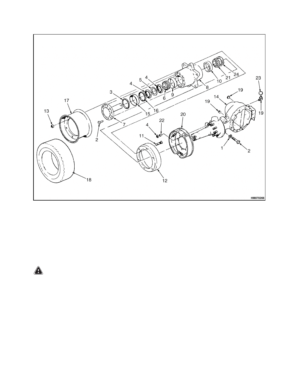
2.
Remove the wheel nuts, wheel, and brake drum.
See Figure 2.
3.
Remove the lock nut, lockwasher, and adjust-
ment nut from the spindle. Remove the hub.
4.
If necessary, remove the parts of the brake as-
sembly as described in the section Brake Sys-
tem 1800 SRM 452.
2
1400 SRM 450
Drive Axle Repair
1.
WASHER
2.
CAPSCREW
3.
OUTER SEAL
4.
ADJUSTMENT NUT
5.
LOCKWASHER
6.
OUTER BEARING CONE
7.
AXLE SHAFT
8.
HUB
9.
OUTER BEARING CUP
10. INNER BEARING CUP
11. STUD
12. BRAKE DRUM
13. WHEEL NUT
14. AXLE HOUSING
15. WEAR SLEEVE
16. GASKET
17. WHEEL
18. TIRE
19. FITTING
20. BRAKE
21. INNER BEARING CONE
22. THIMBLE
23. PLUG
24. INNER SEAL
Figure 2. Drive Axle Assembly
CLEAN
WARNING
Always wear safety glasses.
Cleaning solvents may be flammable and toxic
and can cause severe skin irritation. When us-
ing cleaning solvents, always comply with the
solvent manufacturer’s recommended safety
precautions.
Compressed air can move particles so they
cause injury to the user or to other personnel.
Make sure that the path of the compressed air
is away from all personnel.
Wear protective
goggles or a face shield to prevent injury to
the eyes.
Clean the parts of the axle with solvent. Dry the
parts with compressed air.
INSPECT
Inspect the bearings, bearing surfaces, and seals for
defects. Inspect the splines on the axle shafts for
damage.
3
Drive Axle Repair
1400 SRM 450
ASSEMBLE
WARNING
Hot parts. Wear protective clothing and gloves
to prevent burns.
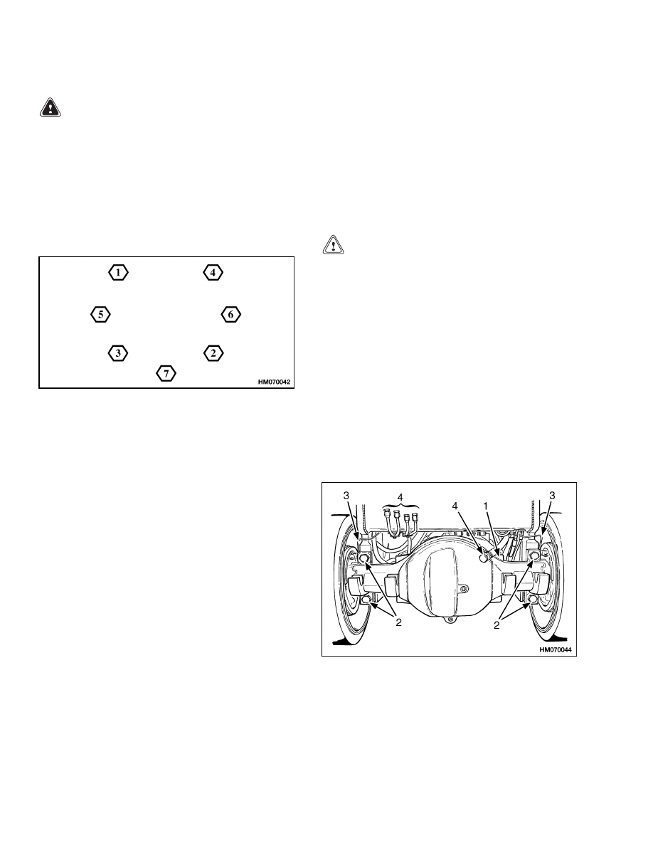
1.
If removed, install the brake assembly as de-
scribed in the section Brake System 1800 SRM
452. Tighten the nuts for the backing plate to 55
to 80 N•m (40 to 59 lbf ft) torque in the cross pat-
tern shown in Figure 3. Tighten the nuts in the
same cross pattern using a hand torque wrench
to 110 to 125 N•m (81 to 92 lbf ft).
Figure 3. Brake Cross Pattern
2.
Install the inner seal and inner bearing cone on
the spindle. Install both bearing cups in the hub.
See Figure 2.
3.
Fill both bearing cones with the grease specified
in the Maintenance Schedule of the Operating
Manual or the section Periodic Maintenance
8000 SRM 393. Fill the area between the bear-
ings in the hub with the same grease.
4.
Install the hub on the spindle and install the
outer bearing cone on the spindle. Install the ad-
justment nut.
5.
Do the following procedure to adjust the wheel
bearings:
a. Tighten the adjustment nut to 200 N•m
(148 lbf ft) torque while rotating the hub.
Loosen the adjustment nut so the hub turns
freely. The torque must be less than 27 N•m
(20 lbf ft). Tighten the adjustment nut again
so the pin of the lockwasher is alignment at
35 N•m (26 lbf ft) or more.
b. Install the lockwasher. Make sure the pin en-
gages the adjustment nut. Tighten the lock
nut to 135 N•m (100 lbf ft).
c.
Install the brake drums and wheels. Tighten
the wheel nuts to 610 to 680 N•m (450 to
502 lbf ft).
INSTALL
Units With Manual Transmission
The normal procedure is to install the manual trans-
mission and the drive axle as an assembly. See the
section Three-Speed Manual Transmission 1300
SRM 335 to install the drive axle.
CAUTION
Make sure the brake lines are through the
openings in the frame as the assembly moves
under the lift truck. Do not damage the brake
or hydraulic lines or the fittings as the axle
assembly moves into position.
1.
Use a sealant (Hyster Part No. 264159) on both
sides of the seal flange and the edge of the hub
where the axle shaft touches the hub. See Fig-
ure 2. Install the gasket, wear sleeve, and seal
on the spindle. Install the axle shaft. Tighten
the capscrews in a cross pattern to 165 N•m
(122 lbf ft).
2.
Install the four large capscrews that hold the
drive axle assembly to the frame. See Figure 4.
Tighten the capscrews to 1040 N•m (768 lbf ft).
NOTE: PLUG CAN BE IN DIFFERENT LOCATION.
1.
DRIVE AXLE
ASSEMBLY
2.
MOUNT
CAPSCREW
3.
BRAKE LINE
4.
HYDRAULIC LINE
Figure 4. Drive Axle Assembly
4

1400 SRM 450
Torque Specifications
3.
Connect the brake lines to the wheel cylinders.
4.
Connect the parking brake cables to the hand
lever. Connect the parking brake mechanism to
the frame. Install the parking brake lever on the
cowl.
5.
Fill the axle housing with the oil specified in the
Maintenance Schedule of the Operating Man-
ual or the section Periodic Maintenance 8000
SRM 393.
6.
Install the upright and carriage as described in
the section Masts Description and Repair
4000 SRM 329.
7.
Remove the air from the brake system as de-
scribed in the section Brake System 1800 SRM
452.
Units With Powershift Transmission
Install the drive axle and differential as a unit.
1.
Connect a lifting device to the input end of the
differential.
Use a sealant (Hyster Part No.
264159) on the flange of the differential.
In-
stall the differential in the drive axle housing.
Tighten the capscrews in a cross pattern to
66 N•m (49 lbf ft).
2.
Use a sealant (Hyster Part No. 264159) on both
sides of the seal flange and the edge of the hub
where the axle shaft touches the hub. See Fig-
ure 2. Install the gasket, wear sleeve, and seal
on the spindle. Install the axle shaft. Tighten
the capscrews in a cross pattern to 165 N•m
(122 lbf ft).
CAUTION
Make sure the brake lines are through the
openings in the frame as the assembly moves
under the lift truck. Do not damage the brake
or hydraulic lines or the fittings as the axle
assembly moves into position.
3.
Slowly move the drive axle assembly into posi-
tion under the lift truck. Install the drive shaft.
4.
Install the four large capscrews that hold the
drive axle assembly to the frame. See Figure 4.
Tighten the capscrews to 1040 N•m (768 lbf ft).
5.
Connect the brake lines to the wheel cylinders.
Do not over tighten the fittings and damage the
threads.
6.
Connect the parking brake cables to the hand
lever. Connect the parking brake mechanism to
the frame. Install the parking brake lever on the
cowl. On units with a MONOTROL pedal, install
the rod for the parking brake switch.
7.
Fill the axle housing with the oil specified in the
Maintenance Schedule of the Operating Man-
ual or the section Periodic Maintenance 8000
SRM 393.
8.
Install the upright and carriage as described in
the section Masts Description and Repair
4000 SRM 329.
9.
Remove the air from the brake system. Check
that the service brakes and the parking brake
operate correctly. Check for brake fluid leaks.
See the section Brake System 1800 SRM 452.
Torque Specifications
Axle Housing-to-Frame Capscrews
1040 N•m (768 lbf ft)
Axle Adjustment Nut
200 N•m (148 lbf ft) while rotating hub. Then
back to free hub rotation. Must be less than
27 N•m (20 lbf ft). Tighten to first alignment
at or above 35 N•m (26 lbf ft).
Axle Lock Nut
135 N•m (100 lbf ft)
Axle Shaft Capscrews
165 N•m (122 lbf ft)
Wheel Nuts
610 to 680 N•m (450 to 502 lbf ft)
Differential-to-Axle Housing Capscrews
66 N•m (49 lbf ft)
5

Troubleshooting
1400 SRM 450
Troubleshooting
PROBLEM
POSSIBLE CAUSE
PROCEDURE OR ACTION
The lift truck will not move.
An axle shaft is broken.
Install new axle shaft.
The capscrews that hold the axle
shaft to the hub are broken.
Replace the capscrews.
The differential is damaged.
Repair the differential.
Pinion is damaged.
Install a new pinion.
Cluster gear or reduction gear is
damaged.
Install new gear(s).
The drive axle has leaks.
The drain or fill plug has damaged
threads, is loose or missing.
Repair threads. Tighten plug. Install
missing part.
The O-rings or seals have damage.
Install new O-rings and seals.
The drive axle housing is cracked.
Install new drive axle housing.
Speed reducer housing is cracked.
Install a new housing.
The drive axle makes noise.
The bearings have damage.
Install new parts.
The brake assembly is damaged.
Repair brake assembly.
The oil level is low.
Fill as required. Check for leaks.
The axle mounting capscrews are
loose.
Tighten
capscrews
to
specified
torque.
Speed reducer gears are damaged.
Install new gears.
6


TECHNICAL PUBLICATIONS
1400 SRM 450
9/03 (9/95)(3/89) Printed in United Kingdom
Document Outline
- toc
Wyszukiwarka
Podobne podstrony:
1494953 1400SRM0944 (09 2003) UK EN
1498445 1400SRM0945 (09 2003) UK EN
1510463 1400SRM0984 (09 2003) UK EN
910073 1400SRM0049 (09 2003) UK EN
1466247 1400SRM0731 (09 2003) UK EN
897394 1900SRM0453 (09 2003) UK EN
897987 1800SRM0659 (09 2003) UK EN
1494955 2000SRM0943 (09 2003) UK EN
897110 1900SRM0328 (09 2003) UK EN
897993 1600SRM0671 (09 2003) UK EN
897392 1600SRM0451 (09 2003) UK EN
1466235 1600SRM0733 (09 2003) UK EN
1466223 1900SRM0753 (09 2003) UK EN
więcej podobnych podstron