STEERING SYSTEM
H14.00-20.00XM [A214];
H16.00-18.00XM-12EC (H400-450H-EC) [A214]
PART NO. 897993
1600 SRM 671

SAFETY PRECAUTIONS
MAINTENANCE AND REPAIR
• When lifting parts or assemblies, make sure all slings, chains, or cables are correctly
fastened, and that the load being lifted is balanced. Make sure the crane, cables, and
chains have the capacity to support the weight of the load.
• Do not lift heavy parts by hand, use a lifting mechanism.
• Wear safety glasses.
• DISCONNECT THE BATTERY CONNECTOR before doing any maintenance or repair
on electric lift trucks.
• Disconnect the battery ground cable on internal combustion lift trucks.
• Always use correct blocks to prevent the unit from rolling or falling. See HOW TO PUT
THE LIFT TRUCK ON BLOCKS in the Operating Manual or the Periodic Mainte-
nance section.
• Keep the unit clean and the working area clean and orderly.
• Use the correct tools for the job.
• Keep the tools clean and in good condition.
• Always use HYSTER APPROVED parts when making repairs. Replacement parts
must meet or exceed the specifications of the original equipment manufacturer.
• Make sure all nuts, bolts, snap rings, and other fastening devices are removed before
using force to remove parts.
• Always fasten a DO NOT OPERATE tag to the controls of the unit when making repairs,
or if the unit needs repairs.
• Be sure to follow the WARNING and CAUTION notes in the instructions.
• Gasoline, Liquid Petroleum Gas (LPG), Compressed Natural Gas (CNG), and Diesel fuel
are flammable. Be sure to follow the necessary safety precautions when handling these
fuels and when working on these fuel systems.
• Batteries generate flammable gas when they are being charged. Keep fire and sparks
away from the area. Make sure the area is well ventilated.
NOTE:
The following symbols and words indicate safety information in this
manual:
WARNING
Indicates a condition that can cause immediate death or injury!
CAUTION
Indicates a condition that can cause property damage!

Steering System
Table of Contents
TABLE OF CONTENTS
General ...............................................................................................................................................................
Description .........................................................................................................................................................
Steering Wheel and Column Assembly Repair ................................................................................................
General ...........................................................................................................................................................
Steering Wheel and Horn..............................................................................................................................
Remove.......................................................................................................................................................
Install .........................................................................................................................................................
Steering Control Unit Repair ............................................................................................................................
Description .....................................................................................................................................................
Operation .......................................................................................................................................................
Load Sensing Steering ..............................................................................................................................
Remove ...........................................................................................................................................................
Disassemble ...................................................................................................................................................
Clean ..............................................................................................................................................................
Assemble and Install .....................................................................................................................................
Steering System Air Removal ...........................................................................................................................
Steering Relief Pressure Check.........................................................................................................................
Troubleshooting..................................................................................................................................................
This section is for the following models:
H14.00-20.00XM [A214];
H16.00-18.00XM-12EC (H400-450H-EC) [A214]
©2003 HYSTER COMPANY
i

"THE
QUALITY
KEEPERS"
HYSTER
APPROVED
PARTS
1600 SRM 671
Description
General
This section has the description and repair procedures for the parts of the steering system. Description and
repair information is given for the steering wheel and column assembly and the steering control unit. Repair
information for the parts of the steering axle is in the section Steering Axle 1600 SRM 658.
Description
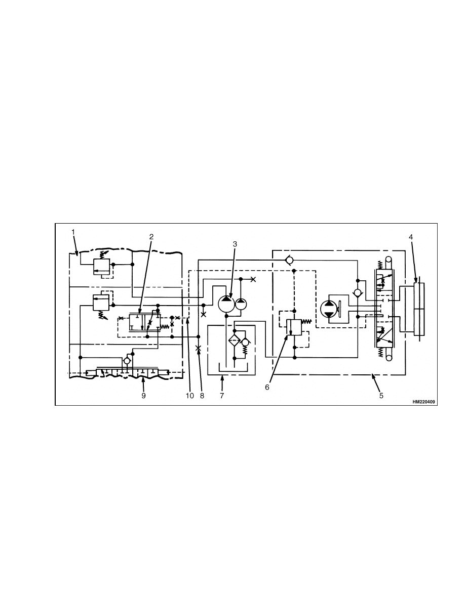
These lift trucks use a hydraulic steering system.
See Figure 1 and Figure 2. The hydraulic pump is
driven by the transmission and supplies oil to the
priority valve. The priority valve is operated by the
sense line in such a way that, when the steering
wheel is not being turned, the hydraulic supply goes
to the lift spool, and when the steering wheel is being
turned, the hydraulic supply goes to the steering
control unit for steering.
When the engine is not running, a check valve closes
and permits the steering control unit to give manual
control to the steering system. The lift truck is diffi-
cult to steer when the steering pump is not operating,
but the steering remains and is possible.
1.
MAIN CONTROL VALVE
2.
PRIORITY VALVE
3.
HYDRAULIC PUMP
4.
STEERING CYLINDER
5.
STEERING CONTROL UNIT
6.
RELIEF VALVE
7.
HYDRAULIC TANK
8.
STEERING SYSTEM CHECK PORT
9.
LIFT SPOOL/LIFT VALVE
10. SENSE LINE (LOAD SENSING)
Figure 1. Steering System Schematic Diagram
1
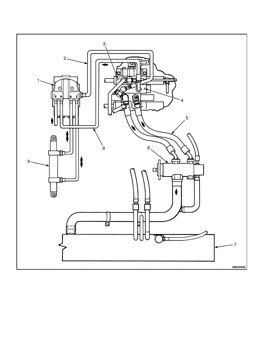
Description
1600 SRM 671
1.
STEERING CONTROL UNIT AND MANIFOLD
BLOCK
2.
SENSE LINE (LOAD SENSING)
3.
MAIN CONTROL VALVE
4.
PRIORITY VALVE SECTION
5.
SUPPLY FROM PUMP
6.
HYDRAULIC PUMP
7.
HYDRAULIC TANK
8.
STEERING SUPPLY
9.
STEERING CYLINDER
Figure 2. Steering System Arrangement
2

1600 SRM 671
Steering Wheel and Column Assembly Repair
Steering Wheel and Column Assembly Repair
GENERAL
The steering control unit and steering column are
mounted to the steering housing. See Figure 3. The
steering housing is mounted on the cowl of the lift
truck and can tilt up or down. The steering wheel is
connected to the steering control unit by the steering
column. The steering wheel is held on the splines of
the steering column with a large nut. The steering
control unit has splines that engage with the lower
end of the shaft in the steering column.
The steering housing is held in position by a spring-
loaded latch assembly. Another spring is the sup-
port for the assembly during adjustment. A cover on
the housing gives access to the steering control unit,
hydraulic lines, and the electrical parts. Five hoses
are connected to the steering control unit and pass
through clamps on the cowl.
Information on the gauges in the steering housing
is in section Instrument Panel Indicators and
Senders 2200 SRM 143.
STEERING WHEEL AND HORN
Remove
This procedure describes the replacement of the
steering wheel and horn actuator assembly. Disas-
semble the parts as required to make repairs.
WARNING
To prevent electrical arcing when removing
the cover, disconnect the negative battery ca-
ble.
1.
Disconnect the negative battery cable.
2.
Remove the horn cover and switch assembly. See
Figure 3. Remove the electrical wire to the horn
switch. Remove the large nut and pull the steer-
ing wheel from the steering shaft with a suitable
puller.
Install
1.
Install the steering wheel and the nut onto the
steering shaft. See Figure 3. Tighten the nut to
35 to 45 N•m (26 to 33 lbf ft).
2.
Attach the electrical wire to the horn switch. In-
stall the horn switch and the horn cover.
3
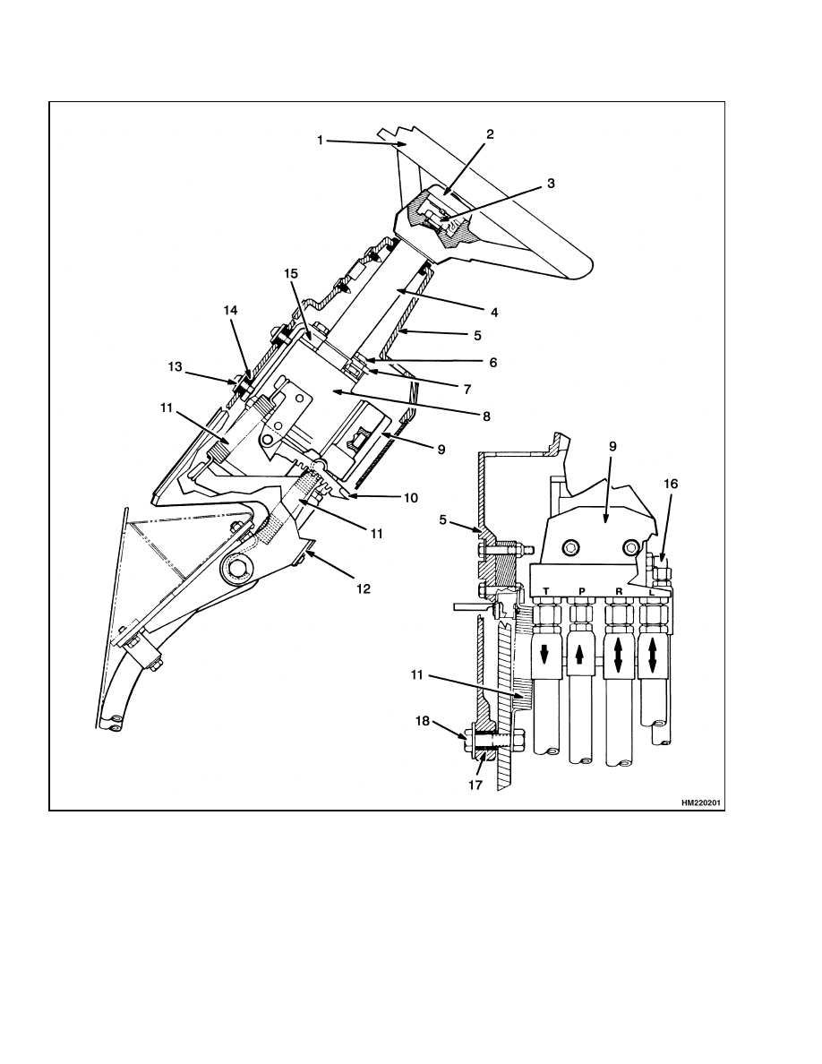
Steering Wheel and Column Assembly Repair
1600 SRM 671
1.
STEERING WHEEL
2.
HORN BUTTON ASSEMBLY
3.
NUT
4.
STEERING COLUMN
5.
STEERING HOUSING
6.
CAPSCREW
7.
BRACKET
8.
STEERING CONTROL UNIT
9.
MANIFOLD BLOCK
10. ADJUSTMENT LATCH
11. SPRING
12. ACCESS COVER
13. CAPSCREW AND WASHER
14. GROMMET
15. SPACER
16. LOAD SENSING PORT
17. BUSHING
18. PIVOT BOLT
Figure 3. Steering Wheel and Steering Column Assembly
4
1600 SRM 671
Steering Control Unit Repair
Steering Control Unit Repair
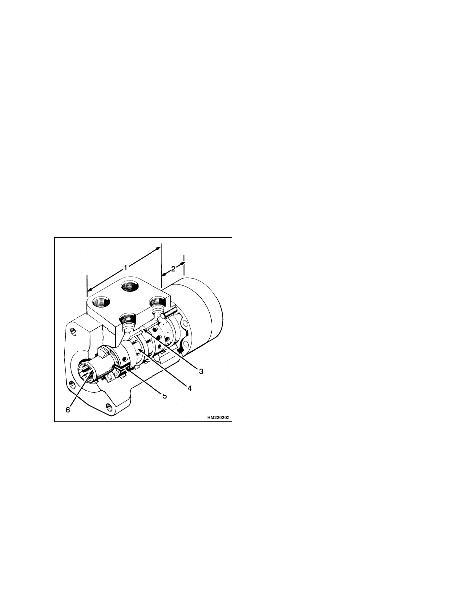
DESCRIPTION
The steering control unit is a hydrostatic unit that
is controlled by the steering wheel. See Figure 4.
It is mounted in the steering housing. The steering
control unit has a shaft assembly, a control section,
and a metering section. The hydraulic hoses for the
steering system are fastened to a manifold block.
Turning the steering wheel actuates three main
parts of the steering control unit: (1) The spool for
the control section, (2) the sleeve for the control
section, and (3) the rotor in the metering section.
When the steering wheel is not moving, the spool
and sleeve are held in the neutral (center) position
by springs. During this time, oil flows freely through
the priority valve section of the control valve. The
oil does not flow to the steering cylinder.
1.
CONTROL SECTION
2.
METERING SECTION
3.
CHECK BALL (MANUAL OPERATION)
4.
SLEEVE
5.
NEUTRAL POSITION SPRINGS
6.
SPOOL
Figure 4. Steering Control Unit
OPERATION
As the steering wheel is turned, the spool just begins
to rotate. See Figure 4. The springs try to move the
sleeve to keep the neutral position between the spool
and sleeve. However, the force necessary to turn the
rotor is greater than the pressure of the springs. The
springs begin to bend, letting the spool move a small
amount within the sleeve. The spool stops moving
when it touches the center pin. In this position, the
holes in the sleeve and the spool are aligned. Oil
coming into the control unit flows to the metering
section.
More rotation of the steering wheel causes the spool
to rotate the pin. This action causes the rotation of
the sleeve and the rotor in the metering section. The
oil then flows to one side of the steering cylinder. Oil
from the other side of the steering cylinder flows back
to the control section of the steering control unit.
When the steering wheel stops moving, the metering
action in the metering section also stops. The neu-
tral position springs return the sleeve to the neutral
position. When this action occurs, the pressure stays
in the steering cylinder to keep the tires in position.
Oil from the pump flows through the priority valve to
the lift circuit and then back to the hydraulic tank.
To return the tires to the straight position, the steer-
ing wheel must be rotated in the opposite direction.
The steering control unit will operate as described,
but all parts will rotate in the opposite direction.
Load Sensing Steering
The demand for steering is sensed at the load sensing
(LS) port in the steering control unit. The pilot line
from the LS port is connected to the priority valve
in the main control valve. While steering, a spring
and pilot pressure from the LS line hold the regula-
tor spool open for steering. When there is no pres-
sure in the LS line (no steering), pilot pressure from
the hydraulic pump shifts the spool. In this position,
most of the oil for the steering system goes to the lift
circuit.
5
Steering Control Unit Repair
1600 SRM 671
REMOVE
WARNING
To prevent electrical arcing when removing
the cover, disconnect the negative battery ca-
ble.
1.
Remove the cover from the steering housing. See
Figure 3. Remove the steering wheel using a
puller. Put tags on the hydraulic lines at the
manifold block. Disconnect the hydraulic lines
and put caps on the openings.
2.
Remove the four capscrews that fasten the steer-
ing control unit to the bracket and remove the
steering control unit. Remove the steering col-
umn from the steering control unit.
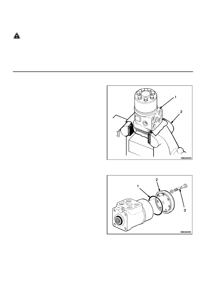
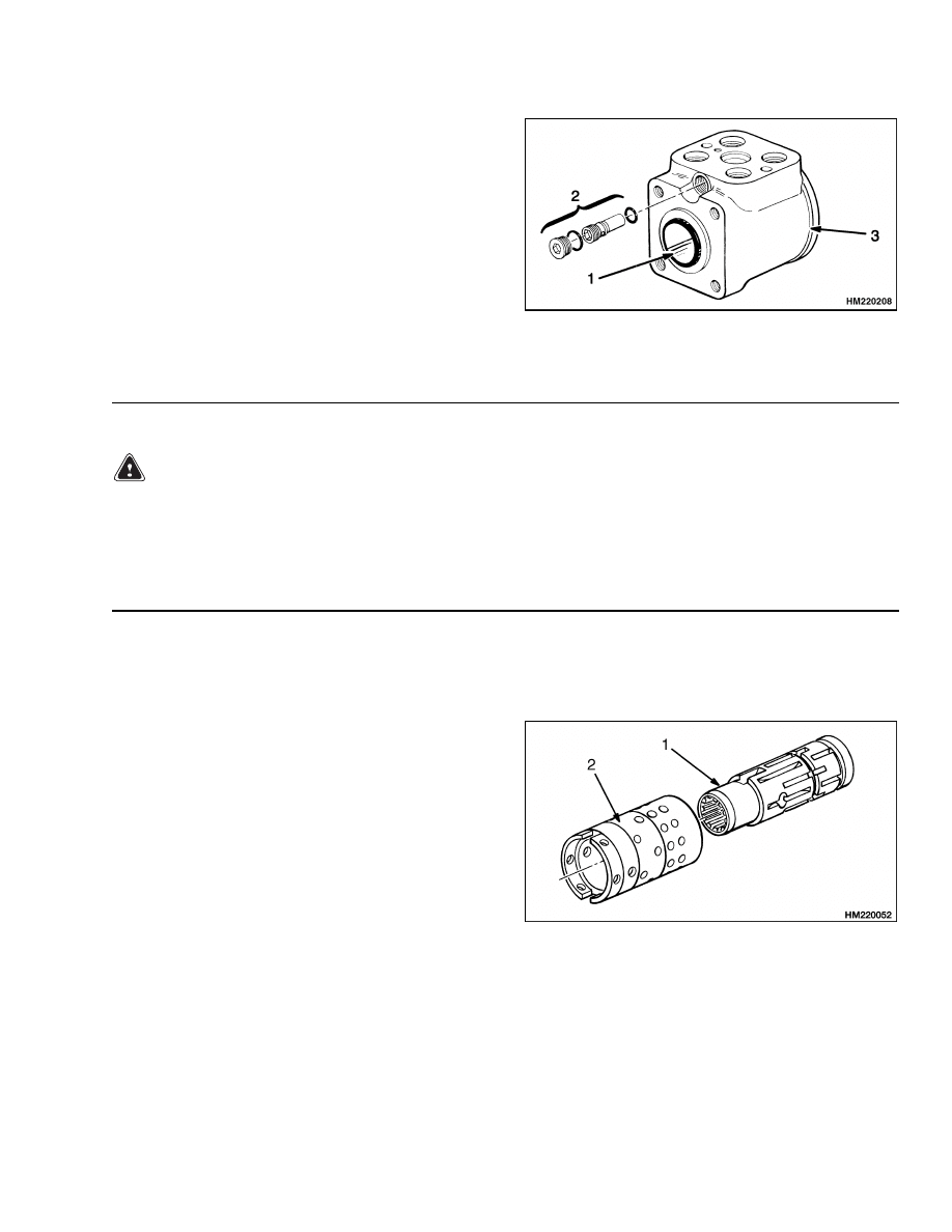
DISASSEMBLE
STEP 1.
Put the control unit in a vise with soft jaws. Make
an identification mark along the length of the control
unit. Put a mark on the stator so that the same side
is toward the body of the control unit. Remove the
manifold block.
1.
STEERING CONTROL UNIT
2.
VISE
STEP 2.
Remove the cover on the bottom of the steering con-
trol unit.
1.
O-RING
2.
COVER
3.
CAPSCREW
6
1600 SRM 671
Steering Control Unit Repair
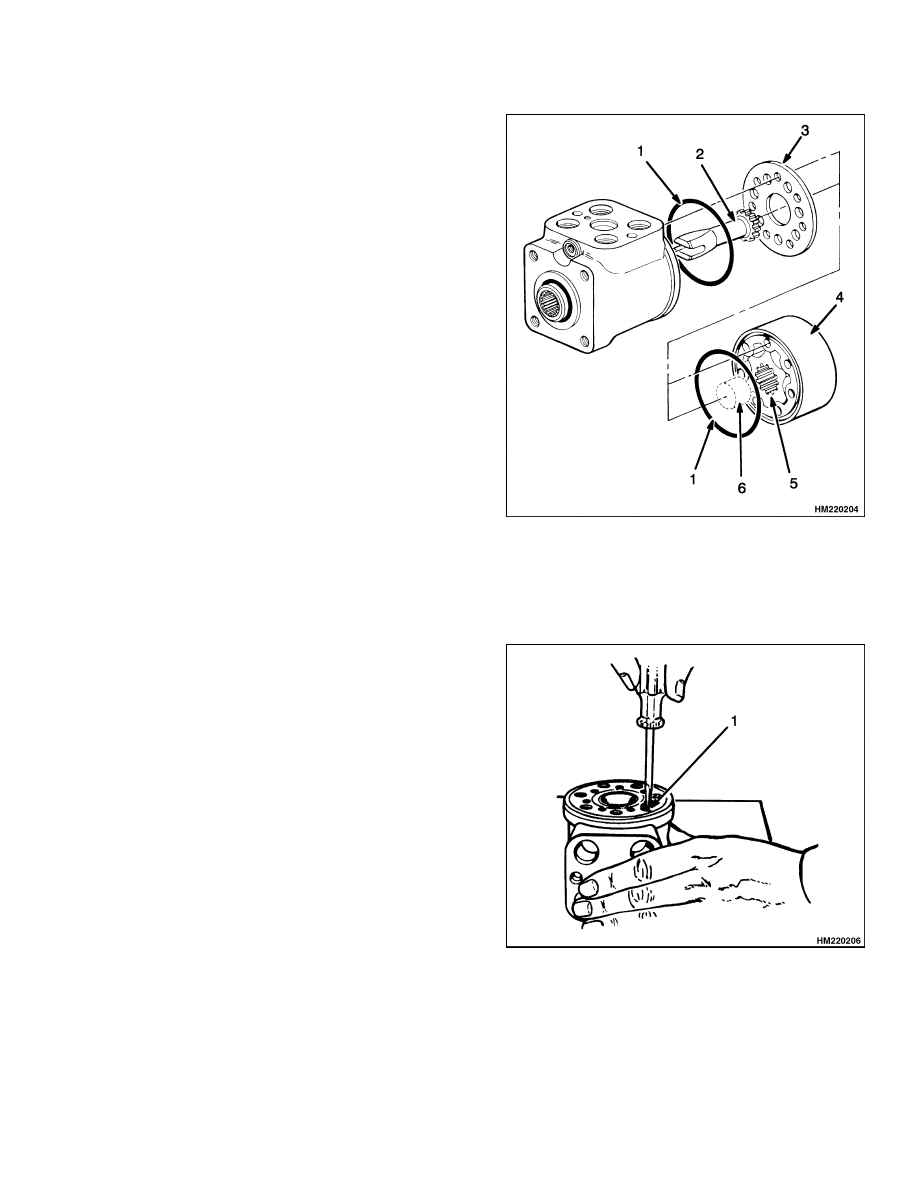
STEP 3.
Remove the spacer, the stator, rotor, and port plate.
Remove the O-rings. Remove the center shaft.
1.
O-RING
2.
CENTER SHAFT
3.
PORT PLATE
4.
STATOR
5.
ROTOR
6.
SPACER
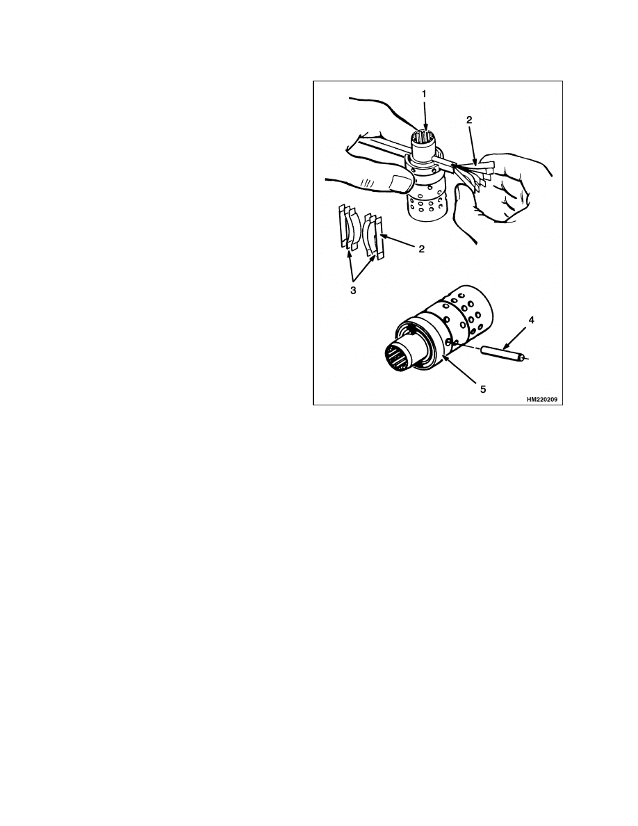
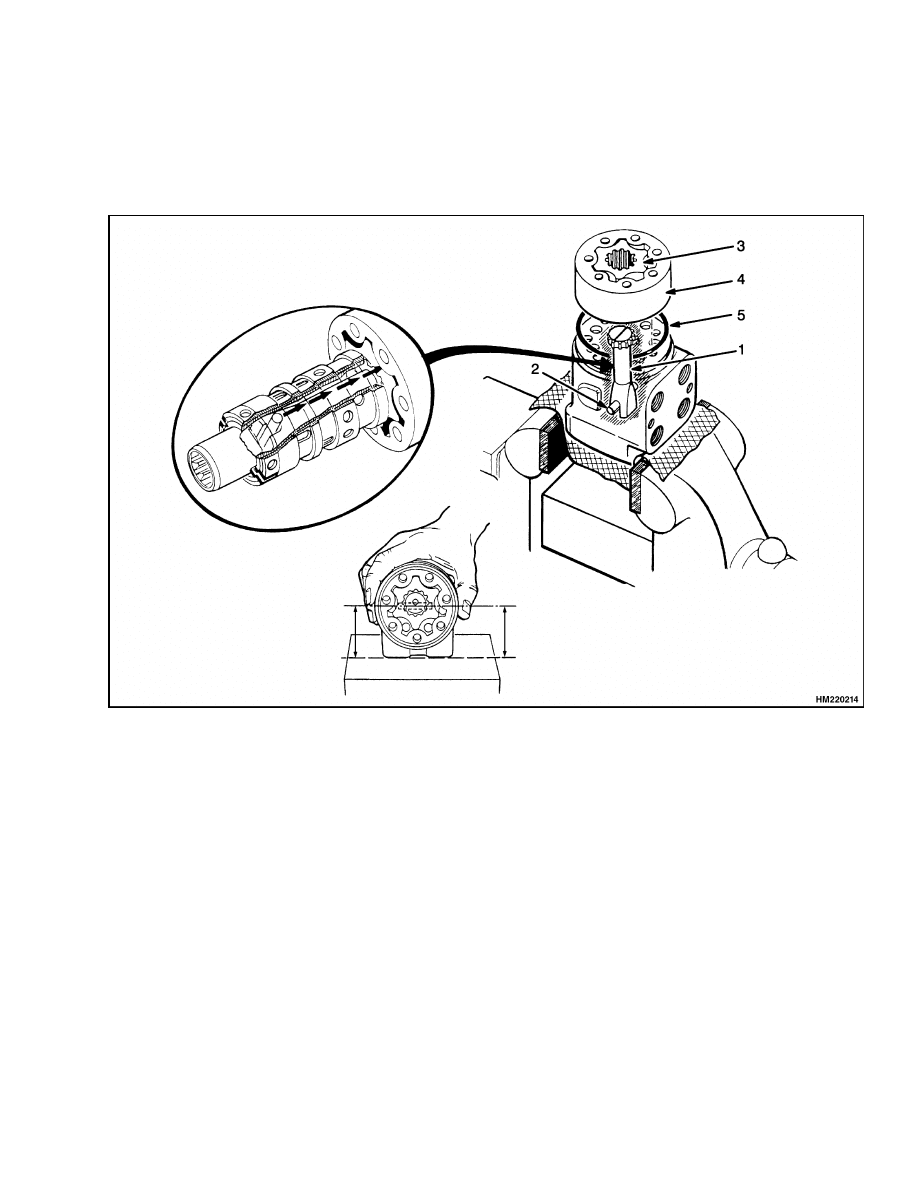
STEP 4.
Remove the retainer for the check ball. Remove the
check ball.
1.
RETAINER
7
Steering Control Unit Repair
1600 SRM 671
STEP 5.
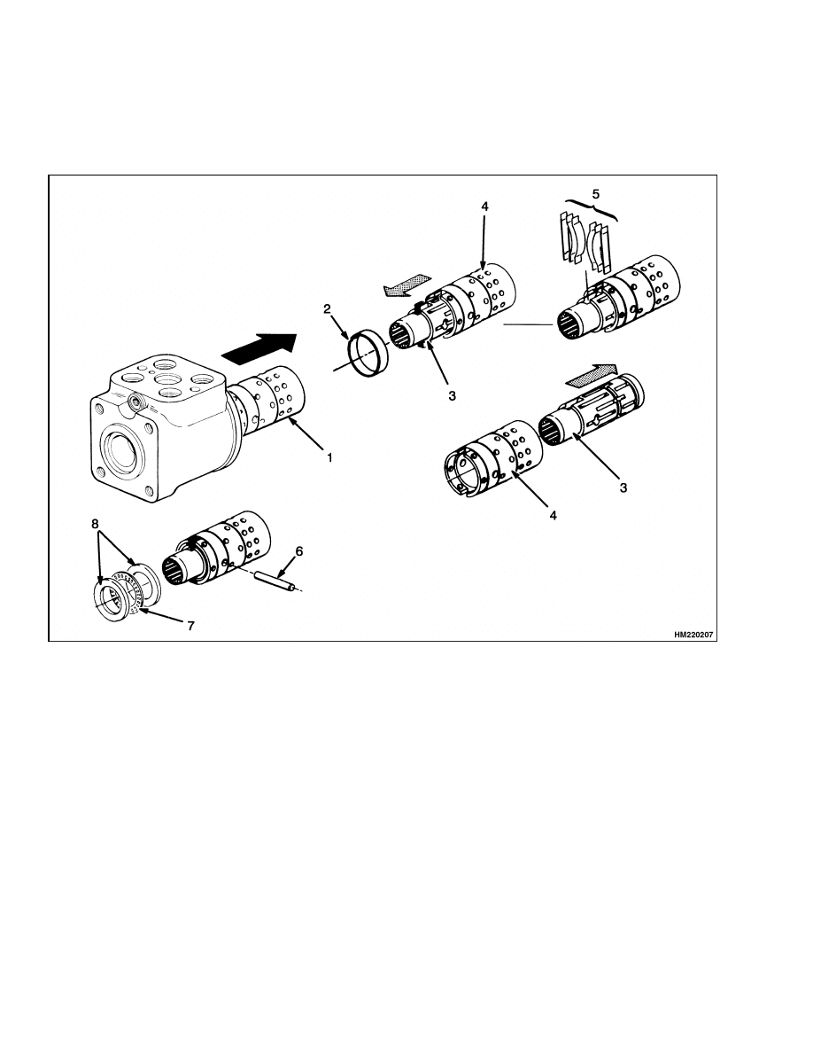
Remove the spool and sleeve assembly. Remove the thrust bearing assembly from the spool. Push the center
pin from the sleeve. Carefully remove the spool from the sleeve. (Rotate the spool slowly during removal.)
Remove the ring from the sleeve. Remove the neutral position springs from the spool.
1.
SPOOL AND SLEEVE ASSEMBLY
2.
RING
3.
SPOOL
4.
SLEEVE
5.
NEUTRAL POSITION SPRINGS
6.
CENTER PIN
7.
THRUST BEARING
8.
THRUST WASHER
8
1600 SRM 671
Steering Control Unit Repair
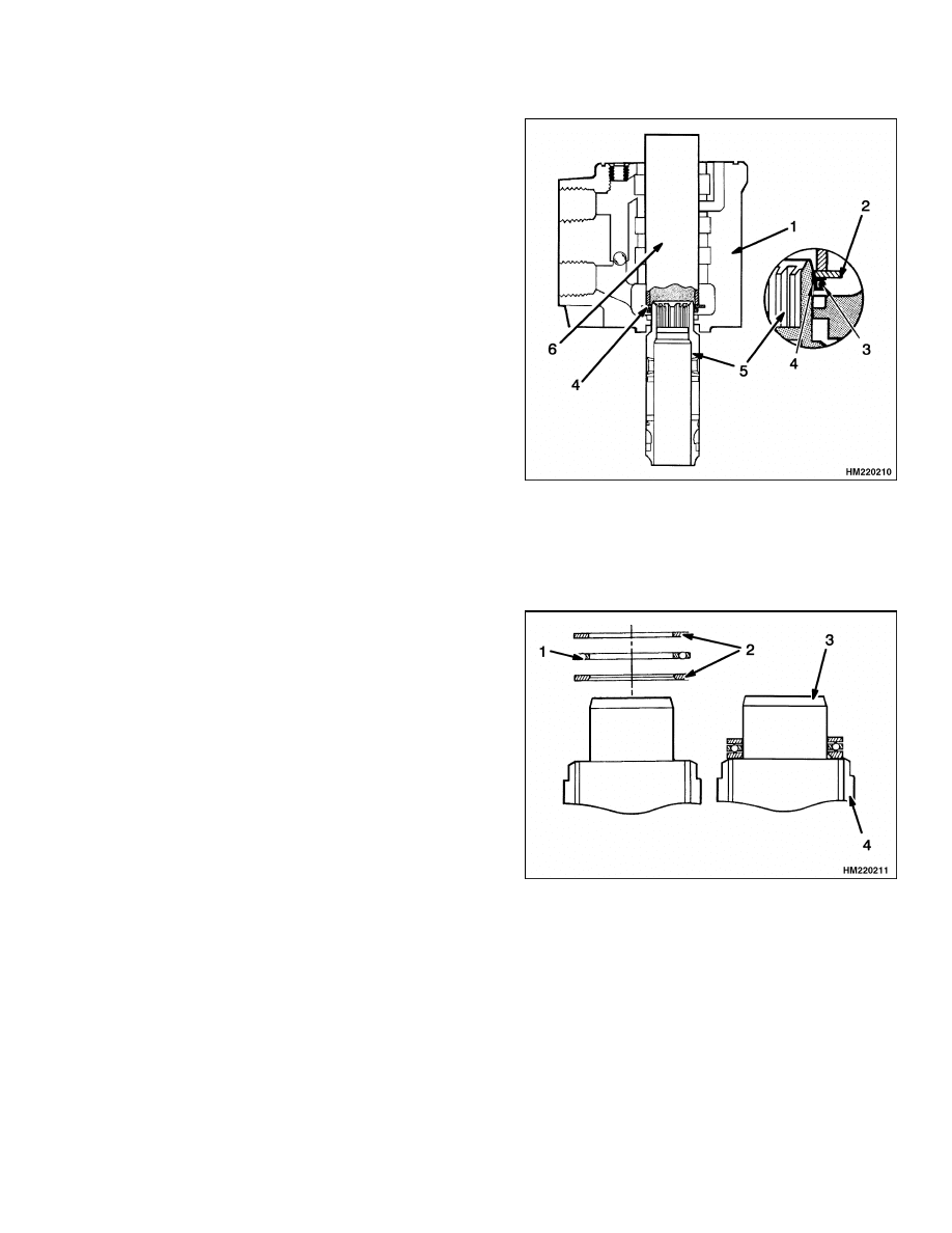
STEP 6.
Remove the relief valve assembly and dust seal from
the housing. Do not disassemble the relief valve car-
tridge.
1.
DUST SEAL
2.
RELIEF VALVE ASSEMBLY
3.
HOUSING
CLEAN
WARNING
Cleaning solvents can be flammable and toxic
and can cause skin irritation.
When using
cleaning solvents, always follow the solvent
manufacturer’s recommended safety precau-
tions.
Clean all the parts in solvent. Dry the parts with
compressed air. Do not dry the parts with a cloth.
Make sure all surfaces are free of scratches and sharp
edges.
ASSEMBLE AND INSTALL
Use new seals, O-rings, and neutral position springs during assembly. Lubricate all parts with clean hydraulic
oil.
STEP 1.
Carefully assemble the spool and sleeve. Make sure
the spool rotates freely in the sleeve. Make sure the
alignment marks are aligned.
1.
SPOOL
2.
SLEEVE
9
Steering Control Unit Repair
1600 SRM 671
STEP 2.
Assemble the neutral position springs, then push
them into position in the spool. Make sure the flat
springs are installed to the outside of the curved
springs. Install the center pin. Install the ring on
the sleeve (over the neutral position springs). The
ring must turn freely on the sleeve.
1.
SPOOL
2.
NEUTRAL POSITION SPRINGS (FLAT)
3.
NEUTRAL POSITION SPRINGS (CURVED)
4.
CENTER PIN
5.
RING
10
1600 SRM 671
Steering Control Unit Repair
STEP 3.
Put the spool on the workbench, then put the hous-
ing onto the spool as shown. Install the guide ring
with the O-ring on the end of the spool. Put a large
thrust washer (see STEP 4) on top of the guide ring
and O-ring assembly. Use a socket or tube to push on
the washer and install the O-ring and guide ring in
the housing. Carefully remove the washer, tube, and
spool from the housing.
1.
HOUSING
2.
WASHER
3.
O-RING
4.
GUIDE RING
5.
SPOOL
6.
TUBE
STEP 4.
Install the thrust washers and thrust bearing on the
spool. Make sure the chamfer on the inner thrust
washer is next to the sleeve.
1.
THRUST BEARING
2.
THRUST WASHER
3.
SPOOL
4.
SLEEVE
11
Steering Control Unit Repair
1600 SRM 671
STEP 5.
Install the spool and sleeve assembly in the housing.
Carefully rotate the spool and sleeve assembly dur-
ing installation to make sure the spool fits correctly
in the seal installed in STEP 3. Make sure the cen-
ter pin on the spool and sleeve assembly is horizontal
(parallel to the surface with the ports).
1.
HOUSING
2.
SPOOL AND SLEEVE ASSEMBLY
STEP 6.
Install the check ball and retainer. Make sure the re-
tainer is even with or below the surface of the hous-
ing. Lubricate the O-ring and install the O-ring and
port plate. Align the holes in the port plate with the
holes in the housing.
1.
CHECK BALL RETAINER
2.
O-RING
3.
PORT PLATE
4.
HOUSING
12
1600 SRM 671
Steering Control Unit Repair
STEP 7.
Install the center shaft so that it engages with the center pin in the spool and sleeve assembly. Make sure the
center pin is still parallel to the surface with the ports. Install the rotor on the center shaft. Make sure that
a valley in the rotor aligns with the slot (center pin) in the center shaft. Install the O-ring and stator. Make
sure to align the marks made during disassembly.
1.
CENTER SHAFT
2.
CENTER PIN
3.
ROTOR
4.
STATOR
5.
O-RING
13
Steering Control Unit Repair
1600 SRM 671
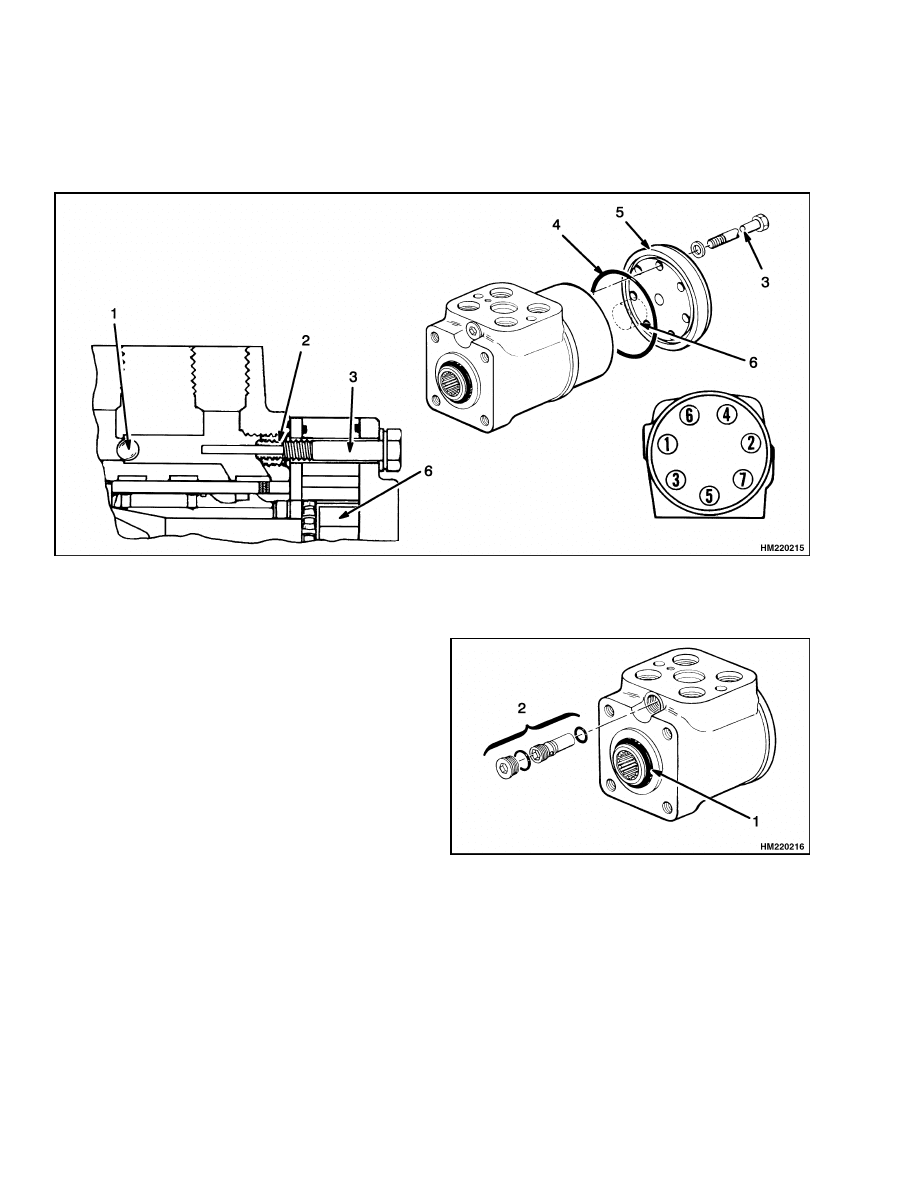
STEP 8.
Install the spacer. Install the O-ring and the cover. Tighten the capscrews for the cover in the sequence shown
to 17 N•m (150 lbf in), then tighten them to 30 N•m (265 lbf in). Make sure the capscrew with the pin fits in
the hole for the check ball.
1.
CHECK BALL
2.
RETAINER
3.
CAPSCREW
4.
O-RING
5.
COVER
6.
SPACER
STEP 9.
Install the dust seal in the housing. Install the relief
valve assembly.
1.
DUST SEAL
2.
RELIEF VALVE ASSEMBLY
14
1600 SRM 671
Steering System Air Removal
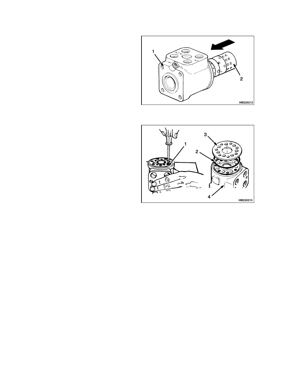
STEP 10.
Install the manifold block and O-rings on the steering
control unit. Tighten the capscrews for the manifold
block to 40 N•m (30 lbf ft).
1.
MANIFOLD BLOCK
2.
O-RING
3.
STEERING CONTROL UNIT
WARNING
After making repairs, do not extend the hands or arms through the steering wheel. If the control
unit was not assembled correctly or the lines not connected correctly, it can rotate with a strong
force and cause injury. If this action occurs, disassemble the control unit, or check the lines to
correct the problem.
STEP 11.
Install the steering column and steering control unit on the bracket. See Figure 3. Connect the hydraulic lines
at the manifold block. Start the engine and operate the steering wheel. Check for correct operation.
Steering System Air Removal
Air can enter the system when a hydraulic line is
disconnected. If the operation is rough, start engine
and rotate steering wheel stop-to-stop several times
in each direction. Air will be removed without dis-
connecting any lines. If the operation is still rough,
air can be entering the system at a loose fitting.
15

Steering Relief Pressure Check
1600 SRM 671
Steering Relief Pressure Check
NOTE:
The relief valve is in the steering control unit.
See Steering Control Unit Repair, Assemble and In-
stall. The relief pressure is set at the factory.
1.
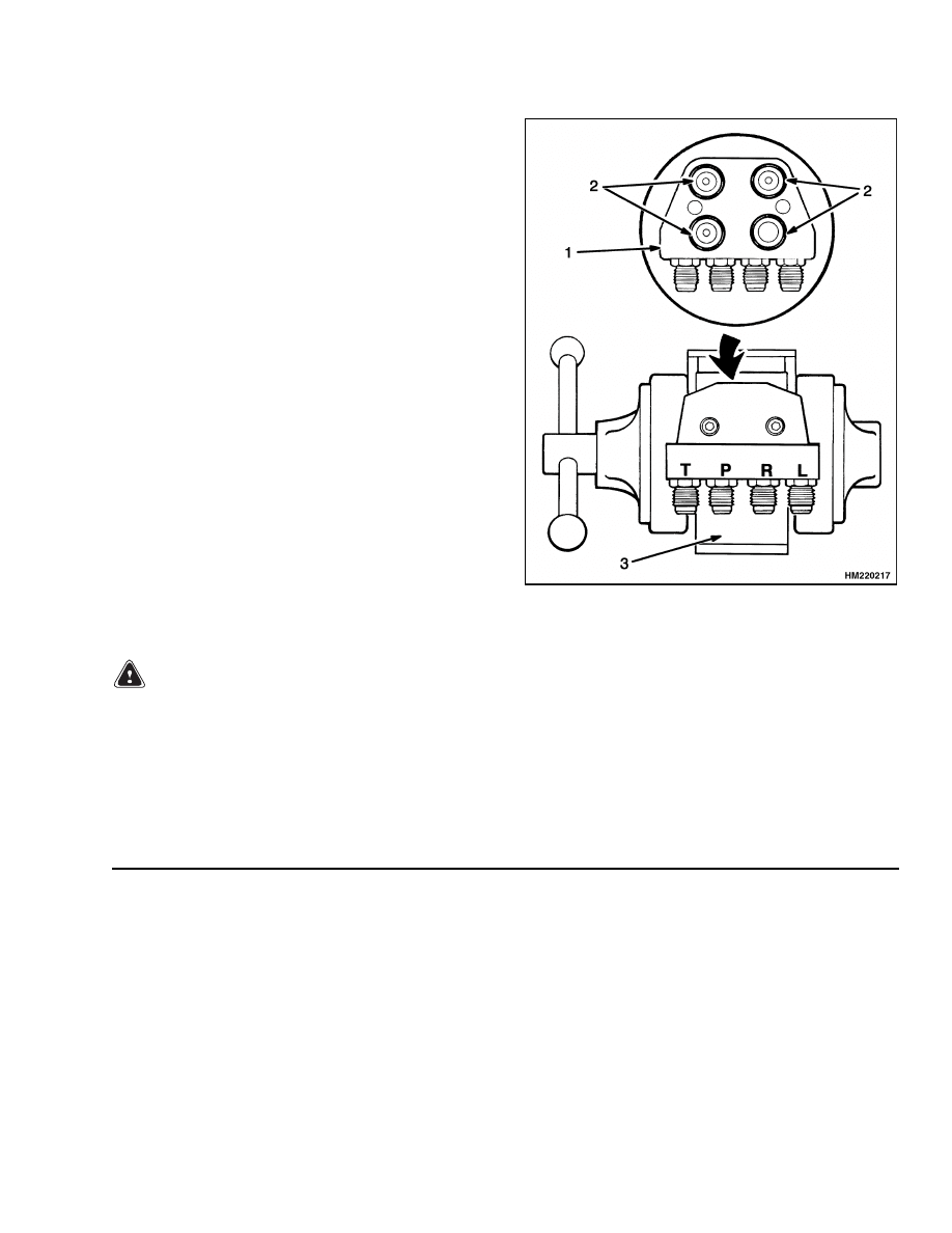
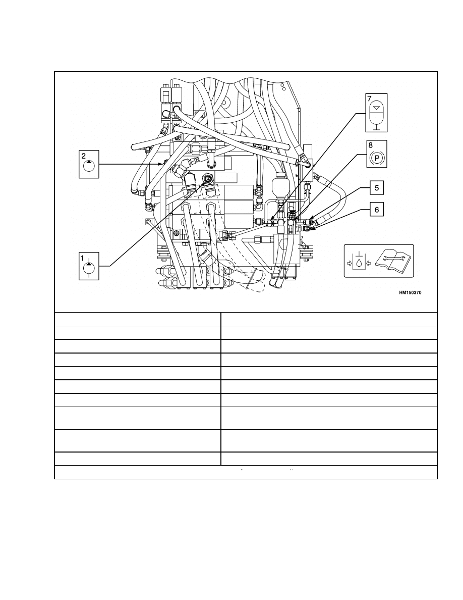
Open the door for the hydraulic compartment.
Connect a 0 to 21 MPa (0 to 3000 psi) gauge to
the test port. See Table 1.
2.
Start the engine. Operate the hydraulic system
until the temperature of the hydraulic oil is 55 to
65 C (130 to 150 F). Run the engine at full throt-
tle when you check the pressure.
3.
Steer in one direction until the wheels will not
turn farther.
Keep the steering wheel fully
turned and read the gauge. The correct relief
pressure is 16.5 MPa (2400 psi).
WARNING
The adjustment screw compresses a spring.
Use caution and wear eye protection when
adjusting the relief valve.
4.
If the relief pressure is not correct, remove the
plug and adjust the pressure by turning the
screw shown in STEP 9 of Steering Control Unit
Repair, Assemble and Install.
If you cannot
correctly adjust the relief pressure, replace the
parts of the relief valve.
5.
When the checks are complete, remove the gauge
and install the cap on the fitting.
16
1600 SRM 671
Steering Relief Pressure Check
Table 1. Hydraulic System Check Ports
Label for Hydraulic System Check Ports
Check Port
Specification
No. 1 - Lift System Relief
23.8 to 24.5 MPa (3450 to 3550 psi) @ full throttle
No. 1 - Tilt/Aux System Relief
18.6 to 19.3 MPa (2700 to 2800 psi) @ full throttle
No. 2 - Lift System Relief
23.8 to 24.5 MPa (3450 to 3550 psi) @ full throttle
No. 2 - Steering System Relief
16.2 to 16.9 MPa (2350 to 2450 psi) @ full throttle
No. 5 - Lift System Pilot Pressure
2.8 to 3.1 MPa (400 to 450 psi) @ idle speed
No. 6 - Tilt/Auxiliary Pilot Pressure
2.8 to 3.1 MPa (400 to 450 psi) @ idle speed
No. 7 - Accumulator Charge Valve (Low)
Pressure
12.1 to 12.8 MPa (1750 to 1850 psi) @ idle speed
No. 7 - Accumulator Charge Valve (High)
Pressure
16.2 to 16.9 MPa (2350 to 2450 psi) @ idle speed
No. 8 - Parking Brake Pressure
6.0 to 6.6 MPa (875 to 925 psi) @ idle speed
Make sure oil is at operating temperature - 54 to 65 C (129 to 150 F).
17

Troubleshooting
1600 SRM 671
Troubleshooting
PROBLEM
POSSIBLE CAUSE
PROCEDURE OR ACTION
There is no action when the
steering wheel is turned.
There is no oil or not enough oil in
the hydraulic tank.
Fill the tank to the correct level.
The lines are loose at the control unit
or manifold block.
Tighten fittings.
The sleeve and spool in the control
unit will not move.
Repair steering control unit.
Steering cylinder leaks.
Repair steering cylinder.
Spacer for center pin is not installed.
Assemble steering control unit cor-
rectly.
The lift truck steers slowly.
The steering wheel is hard
to turn.
The oil level is low. There is no oil in
the tank.
Fill the tank to the correct level.
The lines to the control unit are dam-
aged.
Repair oil lines.
The sleeve and spool in the control
unit are worn.
Repair steering control unit.
The parts of the metering section are
worn.
Repair steering control unit.
The check valve in the control unit
does not open.
Clean or repair steering control unit.
The check valve or relief valve in the
control unit is damaged or is not ad-
justed correctly.
Clean or replace manifold block.
Priority valve is not operating cor-
rectly.
Clean or repair priority valve.
Steering relief pressure is too low.
Adjust relief pressure.
Engine idle speed is too low.
Adjust idle speed to specifications.
The steering wheel turns the
tires in the wrong direction.
The lines at the control unit are not
correctly connected.
Connect lines correctly.
18

1600 SRM 671
Troubleshooting
PROBLEM
POSSIBLE CAUSE
PROCEDURE OR ACTION
The tires continue to turn af-
ter the steering wheel stops.
The neutral position springs are bro-
ken.
Repair steering control unit.
The sleeve or spool has damage.
Repair steering control unit.
Steering wheel kicks back in
both directions.
Center shaft is not correctly aligned
with metering section.
Assemble steering control unit cor-
rectly.
19

NOTES
____________________________________________________________
____________________________________________________________
____________________________________________________________
____________________________________________________________
____________________________________________________________
____________________________________________________________
____________________________________________________________
____________________________________________________________
____________________________________________________________
____________________________________________________________
____________________________________________________________
____________________________________________________________
____________________________________________________________
____________________________________________________________
____________________________________________________________
____________________________________________________________
____________________________________________________________
____________________________________________________________
____________________________________________________________
____________________________________________________________
20


TECHNICAL PUBLICATIONS
1600 SRM 671
9/03 (3/97) Printed in United Kingdom
Document Outline
- toc
- tables
Wyszukiwarka
Podobne podstrony:
897392 1600SRM0451 (09 2003) UK EN
1466235 1600SRM0733 (09 2003) UK EN
1494140 1600SRM0936 (09 2003) UK EN
więcej podobnych podstron