STEERING AXLE
S6.00-7.00XL (S135-155XL, S155XLS,
S135-155XL
2
) [B024, C024]
PART NO. 897392
1600 SRM 451

SAFETY PRECAUTIONS
MAINTENANCE AND REPAIR
• When lifting parts or assemblies, make sure all slings, chains, or cables are correctly
fastened, and that the load being lifted is balanced. Make sure the crane, cables, and
chains have the capacity to support the weight of the load.
• Do not lift heavy parts by hand, use a lifting mechanism.
• Wear safety glasses.
• DISCONNECT THE BATTERY CONNECTOR before doing any maintenance or repair
on electric lift trucks.
• Disconnect the battery ground cable on internal combustion lift trucks.
• Always use correct blocks to prevent the unit from rolling or falling. See HOW TO PUT
THE LIFT TRUCK ON BLOCKS in the Operating Manual or the Periodic Mainte-
nance section.
• Keep the unit clean and the working area clean and orderly.
• Use the correct tools for the job.
• Keep the tools clean and in good condition.
• Always use HYSTER APPROVED parts when making repairs. Replacement parts
must meet or exceed the specifications of the original equipment manufacturer.
• Make sure all nuts, bolts, snap rings, and other fastening devices are removed before
using force to remove parts.
• Always fasten a DO NOT OPERATE tag to the controls of the unit when making repairs,
or if the unit needs repairs.
• Be sure to follow the WARNING and CAUTION notes in the instructions.
• Gasoline, Liquid Petroleum Gas (LPG), Compressed Natural Gas (CNG), and Diesel fuel
are flammable. Be sure to follow the necessary safety precautions when handling these
fuels and when working on these fuel systems.
• Batteries generate flammable gas when they are being charged. Keep fire and sparks
away from the area. Make sure the area is well ventilated.
NOTE:
The following symbols and words indicate safety information in this
manual:
WARNING
Indicates a condition that can cause immediate death or injury!
CAUTION
Indicates a condition that can cause property damage!

Steering Axle
Table of Contents
TABLE OF CONTENTS
General ...............................................................................................................................................................
Description .........................................................................................................................................................
Steering Axle Assembly Repair.........................................................................................................................
Remove ...........................................................................................................................................................
Install .............................................................................................................................................................
Wheels and Hubs Repair ...................................................................................................................................
Remove and Disassemble ..............................................................................................................................
Clean ..............................................................................................................................................................
Assemble and Install .....................................................................................................................................
Spindles, Bearings, and Tie Rods Repair .........................................................................................................
Remove ...........................................................................................................................................................
Clean ..............................................................................................................................................................
Assemble and Install .....................................................................................................................................
Steering Cylinder Repair...................................................................................................................................
Remove and Disassemble ..............................................................................................................................
Clean and Inspect ..........................................................................................................................................
Assemble and Install .....................................................................................................................................
Troubleshooting..................................................................................................................................................
This section is for the following models:
S6.00-7.00XL (S135-155XL, S155XLS, S135-155XL
2
) [B024, C024]
©2003 HYSTER COMPANY
i

"THE
QUALITY
KEEPERS"
HYSTER
APPROVED
PARTS
1600 SRM 451
Description
General
This section has the description and repair procedures for the steering axle. For information on the steering
control unit, see the section Steering Control Unit 1600 SRM 54 .
Description
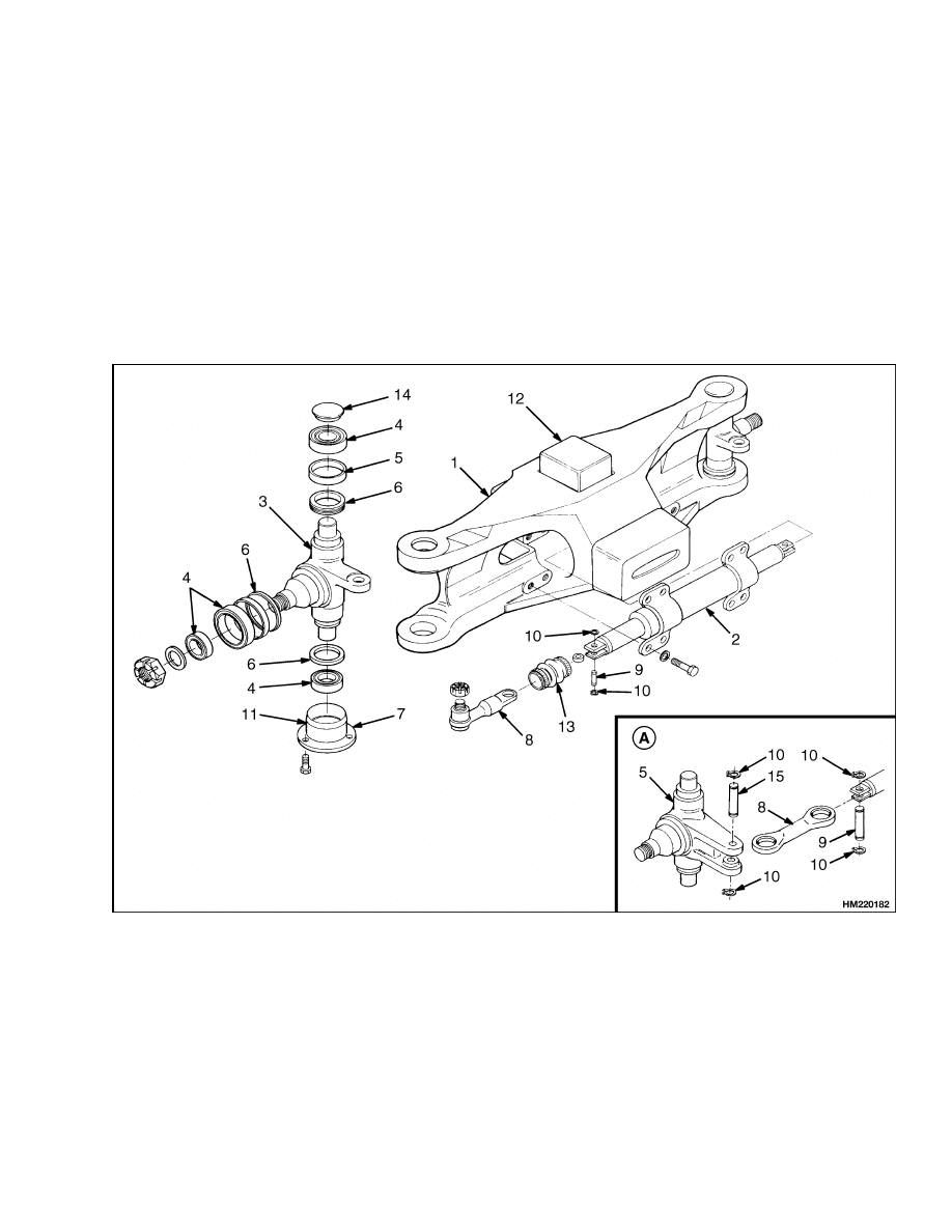
The steering axle assembly includes an axle frame,
steering cylinder, tie rods, and two spindle and hub
assemblies. See Figure 1. The steering axle is articu-
lated and is connected to the frame with center pivot
mounts. The large rubber pivot mounts permit the
steering axle to move in the lift truck frame when the
lift truck travels over rough surfaces. The S7.00XL
(S155XL, S155XLS, S155XL
2
) (B024, C024), also has
a large rubber block at the top center of the steering
axle to cushion vertical shocks.
A. LATER MODELS
1.
AXLE FRAME
2.
STEERING CYLINDER
3.
SPINDLE
4.
BEARING ASSEMBLY (CUP AND CONE)
5.
WEAR SLEEVE
6.
SEAL
7.
SHIMS
8.
TIE ROD
9.
PIN
10. SNAP RING
11. BEARING CAP
12. RUBBER MOUNT
13. DUST COVER
14. GREASE CAP
15. PIN
Figure 1. Steering Axle
1

Steering Axle Assembly Repair
1600 SRM 451
The end caps of the steering cylinder are also the
mounts for the cylinder and are held to the axle by
capscrews. The ends of the piston rod extend from
both ends of the cylinder. A single piston and the
seal are at the center of the piston rod. Oil pressure
on one side of the piston moves the piston in the bore.
The piston pushes an equal amount of oil from the
opposite side of the cylinder. The oil returns to the
steering control unit.
When the piston in the steering cylinder reaches the
end of the stroke, a relief valve controls the oil pres-
sure. The relief valve for the steering system is in the
manifold block that is installed on the steering con-
trol unit. Each spindle turns on two tapered roller
bearings in the axle frame. The preload on the bear-
ings is controlled by shims at the lower bearing cap.
The tie rods that connect the spindle arms to the
cylinder do not have an adjustment.
The wheel hubs rotate on two tapered roller bear-
ings and are held on the spindles by a castle nut.
The bearing preload of the wheel hubs is adjusted by
the castle nut. The grease seals protect the bearings
from dirt and water. Wear sleeves prevent the seals
from causing wear on the hub.
Steering Axle Assembly Repair
REMOVE
WARNING
Put the lift truck on blocks. Follow the pro-
cedures for raising the lift truck that are in
the Operating Manual or the Periodic Mainte-
nance 8000 SRM 393 for this lift truck. The sur-
face must be solid, even, and level. Make sure
the blocks are solid, one-piece units. Make sure
the lifting devices used during repairs can lift
the weight of the parts as given in the proce-
dures.
The steering axle can be removed without removing
the counterweight. See Figure 1.
1.
Make sure the wheels are set for straight travel.
Put blocks under the frame in front of the steer
wheels and under the counterweight so that the
steering axle can be removed. The top of the axle
frame must have clearance under the counter-
weight so that the steering axle can be removed.
2.
Disconnect the hydraulic lines at the steering
cylinder. Install caps on the cylinder and put
plugs in the hydraulic lines. The caps prevent
the spindles from turning when the axle is re-
moved from under the lift truck.
3.
Slide a floor jack or the forks of another lift truck
under the steering axle. Make sure the lifting
device has a capacity of 475 kg (1045 lb). Raise
the lifting device until it holds the weight of the
axle assembly. Remove the four capscrews and
washers that fasten the two brackets under the
rubber mounts. Remove the brackets and slowly
lower the axle assembly onto the tires. Carefully
roll the axle assembly from under the lift truck.
INSTALL
NOTE:
The S7.00XL (S155XL, S155XLS, S155XL
2
)
(B024, C024), has an additional rubber mount on
the top of the steering axle between the axle and lift
truck frame. See Figure 1.
1.
Apply a lubricant that is approved for use with
rubber (tire lubricant) to the rubber mounts and
the lift truck frame at the mount positions. Do
NOT use a petroleum base oil. The lubricant is
used where the rubber mounts fit onto the steer-
ing axle and into the lift truck frame brackets.
2.
Install the rubber mount on the axle with the
heavier section of mount at the top and the
PART NUMBER facing away from the axle
frame.
Install the rubber block in the cen-
ter pocket at the top of the axle on S7.00XL
(S155XL, S155XLS, S155XL
2
) (B024, C024)
units.
3.
Use a floor jack or another lift truck to put the
steering axle into the position in the frame.
Make sure the rubber mounts fit inside the
frame brackets for the mounts.
If necessary,
lower the weight of the lift truck onto the axle to
make sure the rubber mounts fit completely in
the frame brackets.
2
1600 SRM 451
Wheels and Hubs Repair
4.
Install the bottom plates for the rubber mounts.
Tighten the four capscrews for the brackets to
250 to 275 N•m (185 to 203 lbf ft).
5.
Remove the plugs and caps and connect the hy-
draulic lines to the steering cylinder.
6.
Operate the steering system to remove the air
from the system. Turn the steering wheel several
times from one stop to the other stop. Check for
hydraulic leaks.
Wheels and Hubs Repair
REMOVE AND DISASSEMBLE
NOTE:
The wheels and hubs can be removed without
removing the steering axle.
1.
Put the axle or lift truck on blocks so that
the wheels are just raised from the floor. See
Figure 1. See the Operating Manual or the
Periodic Maintenance 8000 SRM 393 to put
the rear of the lift truck on blocks. Remove the
grease cap at the center of the wheel. Remove
the cotter pin and the castle nut. Remove the
bearing cone. Slide the hub from the spindle.
Remove the inner bearing cone and the seal from
the spindle.
2.
If the wheel bearings must be replaced, use a
brass drift to remove the bearing cup and the
wear sleeve.
3.
Repeat the procedure for the other wheel.
CLEAN
WARNING
Cleaning solvents can be flammable and toxic,
and can cause skin irritation.
When using
cleaning solvents, always follow the recom-
mendations of the manufacturer.
Clean all parts with solvent. Make sure the bearings
are clean.
ASSEMBLE AND INSTALL
1.
If the wheel bearings must be replaced, use a
press and the correct tool to install the new bear-
ing cups in the hub. See Figure 1. Install a new
wear sleeve in the wheel hub. Install the grease
seal on the spindle. Fill the bearing cones and lu-
bricate seal surfaces with grease. Make sure the
bearings are filled with grease. Install the bear-
ing cone on the spindle.
CAUTION
Do not damage the seals during installation.
2.
Carefully slide the wheel and hub onto the spin-
dle. Install the outer bearing cone.
3.
Install the washer and castle nut. Tighten the
castle nut to 200 N•m (150 lbf ft) while rotating
the wheel and hub. Loosen the nut to less than
27 N•m (20 lbf ft). Tighten the nut to 34 N•m
(25 lbf ft). Tighten the castle nut until the cotter
pin can be installed. Install the cotter pin. Bend
one end of the cotter pin over the spindle and cut
it flush with the end of the spindle. Bend the
other end of the cotter pin and cut it. Install the
grease cap at the center of the wheel.
4.
Repeat the procedure for the other wheel.
3
Spindles, Bearings, and Tie Rods Repair
1600 SRM 451
Spindles, Bearings, and Tie Rods Repair
REMOVE
CAUTION
Do not hit the threads or the nut of the tie rod.
1.
Early Production Models. If the tie rod must
be replaced, remove the cotter pin and castle nut.
To loosen the stud, hold a large hammer behind
the spindle arm of the spindle. Hit the side of
the spindle arm with another large hammer. The
shock of the hammer from hitting the spindle
arm will normally loosen the tapered stud. If the
stud does not loosen, use a tie rod end puller to
remove the stud.
Later Production Models. Remove the snap
ring from the retainer pin in each tie rod shown
in Figure 1. Remove the pin.
NOTE:
The spindle and tie rod can be removed as
a unit. Disconnect the tie rod at the retaining pin
inside the dust cover. (Use a hammer and a drift to
push the pins) for the tie rods upward.
2.
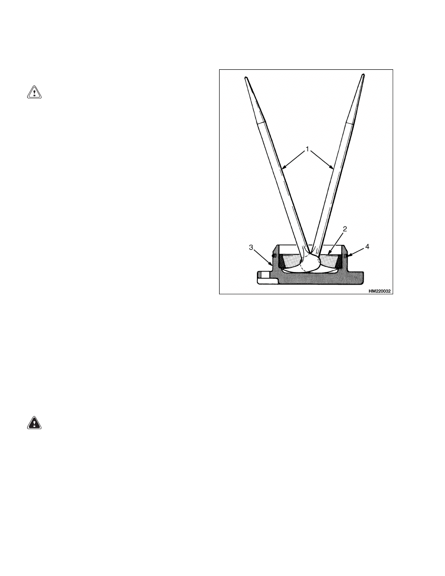
Remove the grease cap at the top of the spindle.
Remove the capscrews from the bearing cap. Re-
move the bearing cap and shims. If necessary,
remove the bearing cup from the bearing cap as
shown in Figure 2.
3.
Tilt the spindle and lift the spindle from the axle.
If the bearing must be replaced, remove the bear-
ing and seals from the spindle. If the wear sleeve
and the bearing cup must be replaced, remove
them from the axle frame.
4.
Repeat the procedure for the other spindle and
tie rod.
CLEAN
WARNING
Cleaning solvents can be flammable and toxic,
and can cause skin irritation.
When using
cleaning solvents, always follow the recom-
mendations of the manufacturer.
Clean all parts except the ends of the tie rods in sol-
vent. Make sure the bearings are clean.
1.
PRY BAR
2.
BEARING CUP
3.
BEARING CAP
4.
O-RING
Figure 2. Bearing Cup Removal
ASSEMBLE AND INSTALL
1.
Install new seals on the spindle. Lubricate the
seals with grease. See Figure 1.
2.
Fill the bearings with wheel bearing grease.
Make sure the bearings are filled with grease. If
necessary, press the new bearing cups into the
steering axle frame and bearing cap. Install the
wear sleeve in the steering axle frame. Install
the seals and bearing cones on the spindle.
3.
Install the spindle in the steering axle. Install
the bearing cap without the O-ring shown in Fig-
ure 2. Tighten the capscrews evenly until all the
clearance is removed from the spindle so that it
cannot move vertically. Measure the clearance
between the bearing cap and the axle to find the
4

1600 SRM 451
Steering Cylinder Repair
correct shim thickness for preload. Remove the
bearing cap. Install shims to decrease the clear-
ance to 0.00 to 0.13 mm (0.000 to 0.005 in.). This
clearance is necessary to give a bearing preload
when the cap is tightened. Install the O-ring on
the bearing cap. Install the bearing cap and cap-
screws. Tighten the capscrews evenly to 52 N•m
(38 lbf ft).
NOTE:
The spindle bearings must have zero clear-
ance. Install shims so that the clearance decreases
to 0.00 to 0.13 mm (0.000 to 0.005 in.). This clear-
ance is necessary for the bearing preload.
4.
Install the tie rod to the spindle arm or steering
cylinder. Install the dust cover over the tie rod.
If removed, tighten the castle nut. Tighten the
castle nut to 160 N•m (118 lbf ft) so that the cot-
ter pin can be installed.
5.
Install the grease cap on the top of the steering
axle. Use a sealant between the grease cap and
the steering axle.
6.
Repeat the procedure for the other spindle and
tie rod.
7.
(Tie rods with grease fittings) Lubricate the spin-
dles at the grease fitting in each bearing cap. Use
the grease specified in the Periodic Maintenance
Schedule of the Operating Manual or the Pe-
riodic Maintenance 8000 SRM 393.
Steering Cylinder Repair
REMOVE AND DISASSEMBLE
NOTE:
The end caps of the steering cylinder are held
in the shell by the cylinder mount capscrews. See
Figure 3. To prevent oil leaks at the end caps, hold
the caps on the shell during removal.
1.
Disconnect the hydraulic lines at the steering
cylinder. Install end caps in the fittings on the
cylinder and put fittings on the hydraulic lines.
2.
Loosen the clamps on both dust covers on the
ends of the steering cylinder rod. Slide the dust
covers from the cylinder rod.
3.
Remove the snap ring from the retainer pin in
each end of the rod shown in Figure 1. Remove
the pin.
4.
Remove the capscrews and washers that fasten
the steering cylinder to the axle frame. Hold the
end caps on the shell and remove the steering
cylinder.
5.
Hold the end of the steering cylinder over a drain
pan. Remove the cap for the hydraulic fitting
from each end cap. Push the rod toward the end
of the shell that is over the drain pan. Oil drains
from the cylinder. Repeat the procedure for the
other end.
6.
Carefully slide one end cap from the shell. Care-
fully pull the rod from the shell. Keep the rod in
the center of the shell during removal. Remove
the end cap from the rod. Remove the other end
cap from the shell. Remove all seals, wipers, and
O-rings.
CLEAN AND INSPECT
WARNING
Cleaning solvents can be flammable and toxic,
and can cause skin irritation.
When using
cleaning solvents, always follow the recom-
mendations of the manufacturer.
WARNING
Compressed air can move particles so that they
cause injury to the user or to other personnel.
Make sure that the path of the compressed air
is away from all personnel.
Wear protective
goggles or a face shield to prevent injury to the
eyes.
1.
Clean all parts in solvent. Use compressed air to
dry the parts.
2.
Inspect the piston rod for grooves or damage. Re-
move small scratches with fine (400 grit) emery
cloth. Inspect the cylinder bore for damage. In-
spect the mounts for cracks.
5
Steering Cylinder Repair
1600 SRM 451
ASSEMBLE AND INSTALL
1.
Put the O-rings, seals, and wipers in warm hy-
draulic oil. Install the O-rings, seals, and wipers
in the correct positions shown in Figure 3.
CAUTION
Do not damage the following items during in-
stallation: O-rings, seals, or wipers.
2.
Lubricate the O-rings, seals, and wipers with
O-ring lubricant and carefully install one end cap
on the rod.
3.
Carefully slide the rod into the shell. Keep the
rod in the center of the shell during installation.
Carefully slide the end cap into the shell. Care-
fully install the other end cap on the rod and
shell. Put caps on the hydraulic fittings of the
end caps.
4.
Hold the end caps and install the steering cylin-
der on the axle frame using the capscrews and
washers. Make sure the end caps are fully en-
gaged with the shell. Tighten the capscrews to
225 N•m (166 lbf ft).
5.
Align the tie rods at each end of the rod. See
Figure 1. Install the pins and snap rings. Slide
the dust covers over the rod so that the edge of
each dust cover is against the shoulder of the rod.
Tighten the clamps at the edge of the dust cover.
6.
Remove the plugs and caps and connect the hy-
draulic lines to the steering cylinder. Start the
engine and operate the steering system to re-
move the air from the cylinder and the system.
Turn the steering wheel several times from one
stop to the other. Check for leaks.
NOTE: The tie rods do not have an adjustment.
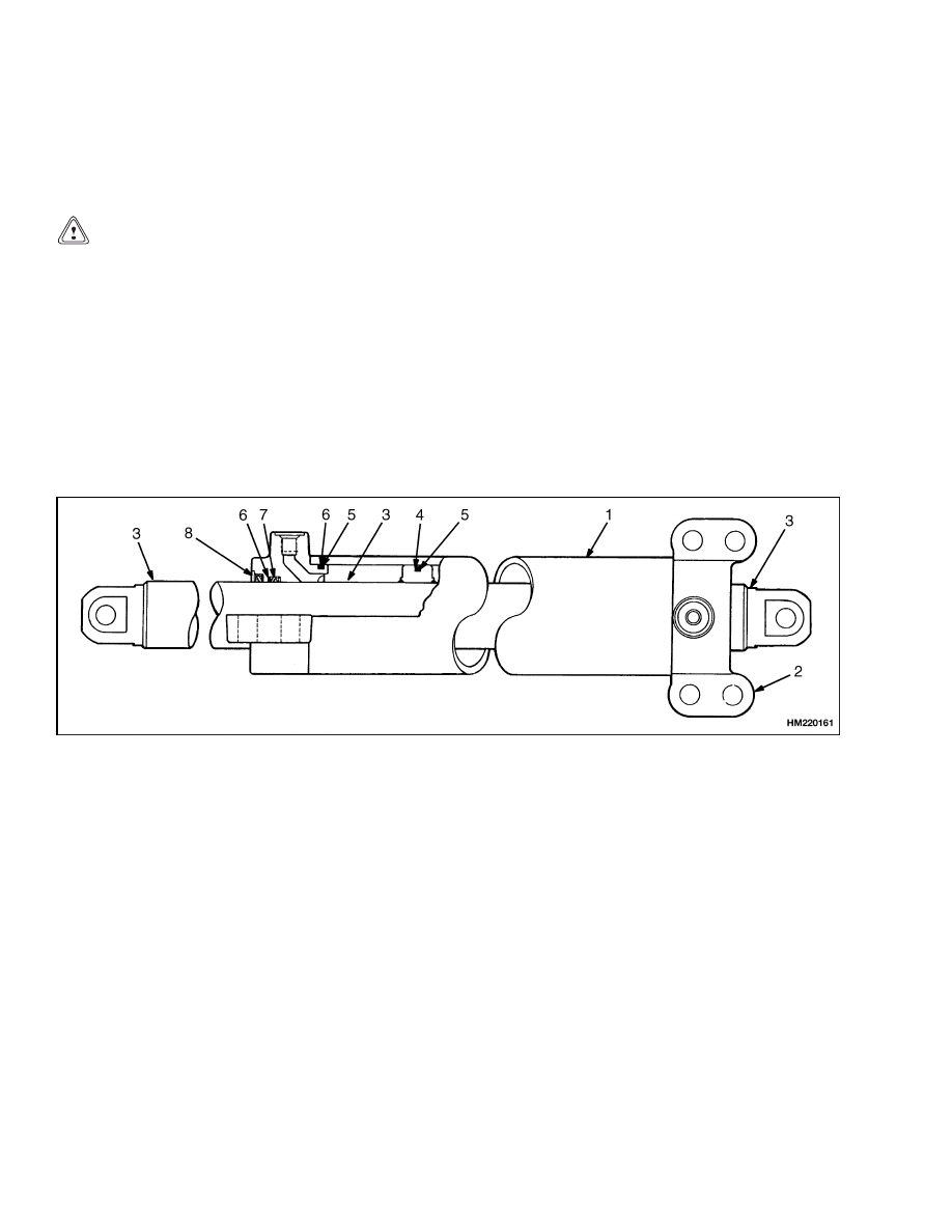
1.
SHELL
2.
END CAP
3.
PISTON ROD
4.
PISTON SEAL
5.
O-RING
6.
BACKUP RING
7.
ROD SEAL
8.
WIPER SEAL
Figure 3. Steering Cylinder
6

1600 SRM 451
Troubleshooting
Troubleshooting
PROBLEM
POSSIBLE CAUSE
PROCEDURE OR ACTION
The steering wheels do not
move
when
the
steering
wheel is turned.
The oil level is low or there is no oil
in the tank.
Fill tank. Check for leaks.
The steering control unit is dam-
aged.
Repair or install new control unit.
No oil flow from the steering control
unit to the steering cylinder.
Repair or install new components.
Check for leaks.
Slow or difficult steering.
Relief valve for the steering system
needs adjustment.
Adjust or install new relief valve.
Low oil pressure from the hydraulic
pump.
Check for restrictions. See the Trou-
bleshooting Chart in the Hydraulic
System 1900 SRM 453.
Seal in the steering cylinder has a
leak.
Install new seal.
Steering control unit is worn or has
damage.
Repair or install new control unit.
Steering wheel turns the
tires in the wrong direction.
The hydraulic lines are not con-
nected correctly at the steering
cylinder or at the steering control
unit.
Connect lines properly. Remove air
from system.
Steering
function
contin-
ues after the steering wheel
stops.
The steering control unit was assem-
bled wrong or has damage.
Repair or install new control unit.
There is air in the steering
system.
The oil level in the tank is low.
Add
hydraulic
oil
as
necessary.
Check for leaks.
Air was not removed after repair to
the hydraulic or steering system.
Remove air from system.
The hydraulic pump has an air leak
at the inlet.
Repair system. Remove air from sys-
tem.
7

NOTES
____________________________________________________________
____________________________________________________________
____________________________________________________________
____________________________________________________________
____________________________________________________________
____________________________________________________________
____________________________________________________________
____________________________________________________________
____________________________________________________________
____________________________________________________________
____________________________________________________________
____________________________________________________________
____________________________________________________________
____________________________________________________________
____________________________________________________________
____________________________________________________________
____________________________________________________________
____________________________________________________________
____________________________________________________________
____________________________________________________________
8


TECHNICAL PUBLICATIONS
1600 SRM 451
9/03 (6/95)(3/89) Printed in United Kingdom
Document Outline
- toc
Wyszukiwarka
Podobne podstrony:
897993 1600SRM0671 (09 2003) UK EN
1466235 1600SRM0733 (09 2003) UK EN
1494140 1600SRM0936 (09 2003) UK EN
1494953 1400SRM0944 (09 2003) UK EN
897394 1900SRM0453 (09 2003) UK EN
1466241 1600SRM0732 (10 2003) UK EN
1498445 1400SRM0945 (09 2003) UK EN
1510463 1400SRM0984 (09 2003) UK EN
897987 1800SRM0659 (09 2003) UK EN
1494955 2000SRM0943 (09 2003) UK EN
897110 1900SRM0328 (09 2003) UK EN
897391 1400SRM0450 (09 2003) UK EN
910073 1400SRM0049 (09 2003) UK EN
1466247 1400SRM0731 (09 2003) UK EN
1466223 1900SRM0753 (09 2003) UK EN
więcej podobnych podstron