DRIVE AXLE
S3.50-5.50XM (S70-120XM) [E004, F004]
PART NO. 1510463
1400 SRM 984

SAFETY PRECAUTIONS
MAINTENANCE AND REPAIR
• When lifting parts or assemblies, make sure all slings, chains, or cables are correctly
fastened, and that the load being lifted is balanced. Make sure the crane, cables, and
chains have the capacity to support the weight of the load.
• Do not lift heavy parts by hand, use a lifting mechanism.
• Wear safety glasses.
• DISCONNECT THE BATTERY CONNECTOR before doing any maintenance or repair
on electric lift trucks.
• Disconnect the battery ground cable on internal combustion lift trucks.
• Always use correct blocks to prevent the unit from rolling or falling. See HOW TO PUT
THE LIFT TRUCK ON BLOCKS in the Operating Manual or the Periodic Mainte-
nance section.
• Keep the unit clean and the working area clean and orderly.
• Use the correct tools for the job.
• Keep the tools clean and in good condition.
• Always use HYSTER APPROVED parts when making repairs. Replacement parts
must meet or exceed the specifications of the original equipment manufacturer.
• Make sure all nuts, bolts, snap rings, and other fastening devices are removed before
using force to remove parts.
• Always fasten a DO NOT OPERATE tag to the controls of the unit when making repairs,
or if the unit needs repairs.
• Be sure to follow the WARNING and CAUTION notes in the instructions.
• Gasoline, Liquid Petroleum Gas (LPG), Compressed Natural Gas (CNG), and Diesel fuel
are flammable. Be sure to follow the necessary safety precautions when handling these
fuels and when working on these fuel systems.
• Batteries generate flammable gas when they are being charged. Keep fire and sparks
away from the area. Make sure the area is well ventilated.
NOTE:
The following symbols and words indicate safety information in this
manual:
WARNING
Indicates a condition that can cause immediate death or injury!
CAUTION
Indicates a condition that can cause property damage!
Drive Axle
Table of Contents
TABLE OF CONTENTS
General ...............................................................................................................................................................
Description .........................................................................................................................................................
Drive Axle Repairs .............................................................................................................................................
Remove and Disassemble ..............................................................................................................................
Clean and Inspect ..........................................................................................................................................
Brakes ........................................................................................................................................................
Drive Axle ..................................................................................................................................................
Assembly and Installation ............................................................................................................................
Torque Specifications .........................................................................................................................................
Troubleshooting..................................................................................................................................................
This section is for the following models:
S3.50-5.50XM (S70-120XM) [E004, F004]
©2003 HYSTER COMPANY
i

"THE
QUALITY
KEEPERS"
HYSTER
APPROVED
PARTS

1400 SRM 984
Drive Axle Repairs
General
This section contains the description and repair
procedures for the drive axle, wheel bearings, and
mounts for the axle housing. For a description of the
differential and ring and pinion gears, see the section
Single-Speed Powershift Transmission - De-
scription and Operation 1300 SRM 399. Repair
procedures for the differential and ring and pinion
gears can be found in the section Single-Speed
Powershift Transmission - Troubleshooting
and Repairs 1300 SRM 397.
Description
The drive axle assembly is fastened to the frame of
the lift truck by separate mounts and can rotate in
the mounts. The outer ends of the axle housings
are the spindles for the wheel bearings. The wheel
bearings are tapered roller bearings with the cups
pressed into the hubs. The nut on the end of the axle
housing adjusts and holds the wheel bearings. The
axle shafts are fastened to the hubs by capscrews and
two dowel pins. The back plate and brake assembly
are fastened to the axle mounts. The axle mounts
also have bearing journals for the upright.
The outer wheel bearing is lubricated by gear oil from
the differential housing. The inner wheel bearing is
lubricated by wheel bearing grease. See Figure 1.
Drive Axle Repairs
REMOVE AND DISASSEMBLE
WARNING
When putting the lift truck on blocks, make
sure the surface is solid, even, and level. Any
blocks used to support the lift truck must be
solid, one-piece units.
1.
Place blocks on each side (front and rear) of steer-
ing tires to prevent movement of lift truck.
2.
Raise lift truck and place blocks under frame so
drive wheels are just touching floor. Place blocks
under counterweight to maintain stability. Drain
oil from differential housing.
3.
Remove mast assembly as directed in Mast - De-
scription and Repairs 4000 SRM 736.
4.
Remove wheel assemblies from drive axle.
5.
Remove capscrews that hold axle shafts to hubs.
There are two holes with threads in the flange
of the axle shaft. Put capscrews in holes to push
axle shaft from hub. Or, hit end of axle shaft with
a soft hammer. Remove axle shaft.
WARNING
Brake
linings
contain
dangerous
fibers.
Breathing the dust from these brake linings
is a cancer and lung disease hazard. Do not
create dust!
Do not clean brake parts with
compressed air or by brushing. Use vacuum
equipment approved for brake dust or follow
the cleaning procedure in this section. When
the brake drums are removed, do not create
dust.
Do not sand, grind, chisel, hammer, or change
linings in any way that will create dust. Any
changes to linings must be done in a restricted
area with special ventilation. Protective cloth-
ing and a respirator must be used.
NOTE:
The following procedure is for one side of the
axle assembly. This procedure applies to both sides.
See Figure 1 and Figure 2.
6.
Remove adjustment nut, lockwasher, and lock
nut. Remove hub and brake drum, bearings, and
seal. Discard the seal. If brake drum cannot be
easily removed, loosen brake shoes by turning
adjuster wheel.
7.
If the brakes need repair, see the section Brake
System 1800 SRM 985.
8.
Disconnect hydraulic brake lines at wheel cylin-
ders. Disconnect parking brake cable at parking
brake lever and loosen cable clamps along frame
for parking brake cable.
1
Drive Axle Repairs
1400 SRM 984
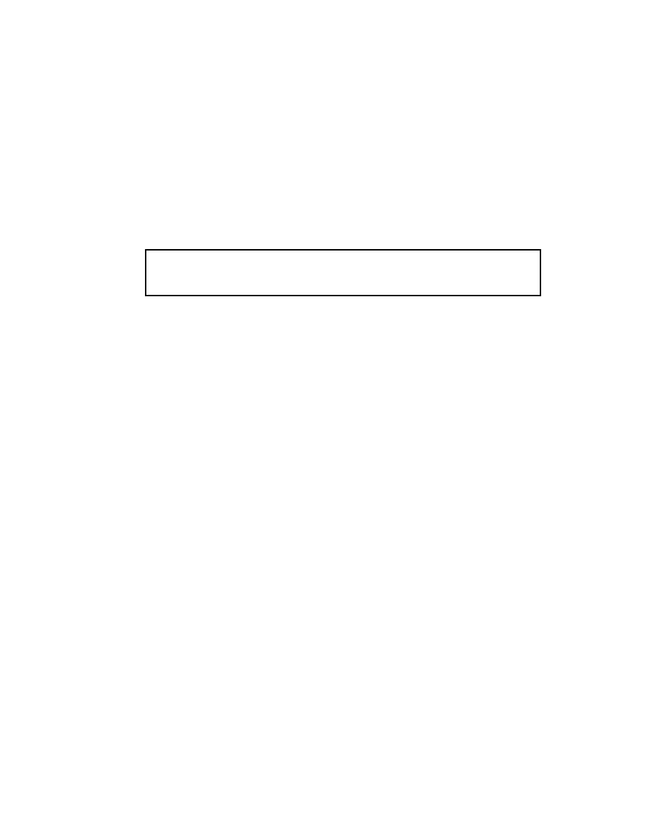
1.
AXLE HOUSING
2.
AXLE MOUNT
3.
BRAKE ASSEMBLY (BRAKE SHOES AND BACK
PLATES)
4.
BRAKE DRUM
5.
SEAL
6.
BEARING CONE
7.
BEARING CUP
8.
HUB
9.
ADJUSTMENT NUT
10. LOCKWASHER
11. LOCK NUT
12. AXLE SHAFT
13. TIRE AND WHEEL
14. MOUNTING PIN
15. DOWEL PIN
Figure 1. Drive Axle Assembly
9.
Remove brake assembly from axle mount.
10. Put a block for support under transmission. Re-
move capscrews holding axle housing to trans-
mission housing.
NOTE:
If axle mounting pins cannot be removed,
soak them in penetrating oil or use a hacksaw blade
to saw a slot in the pins.
11. Use a lifting device to hold weight of axle hous-
ing. Use a puller to remove mounting pins from
frame and axle mount. Remove bolts that hold
axle mounts to frame. See Figure 2.
2
1400 SRM 984
Drive Axle Repairs
12. Remove axle assembly from lift truck. Remove
axle mounts from the drive axle.
13. Remove shims only if they are damaged. Be sure
to note number of shims removed from each side.
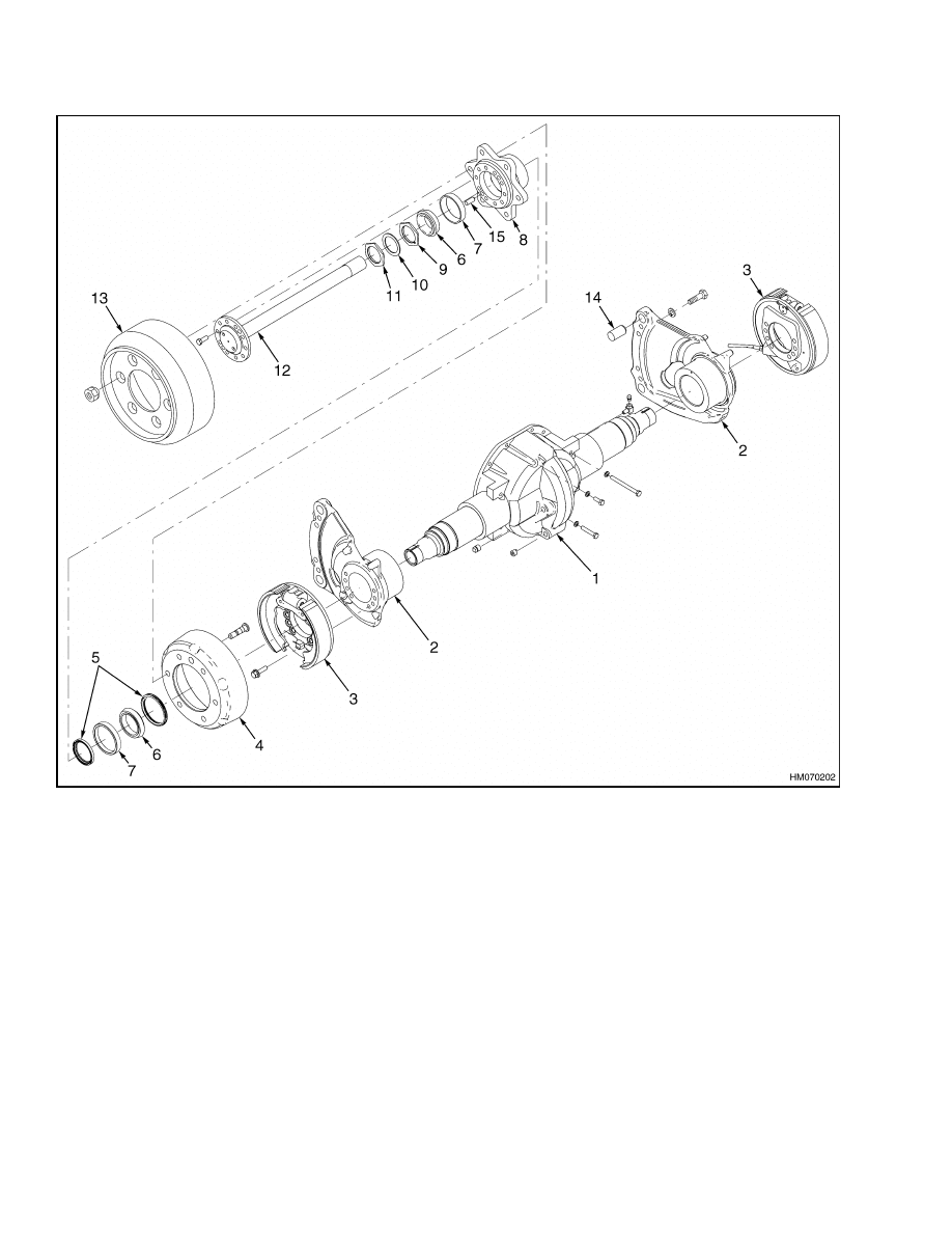
A. REMOVAL
B. INSTALLATION
1.
FRAME
2.
AXLE MOUNT
3.
MOUNTING PIN
4.
BOLT
5.
SPACER
Figure 2. Axle Mounts
CLEAN AND INSPECT
Brakes
WARNING
Cleaning solvents can be flammable and toxic
and can cause skin irritation.
When using
cleaning solvents, always follow the solvent
manufacturer’s recommended safety precau-
tions.
WARNING
Brake
linings
contain
dangerous
fibers.
Breathing the dust from these brake linings
is a cancer and lung disease hazard. Do not
create dust!
Do not clean brake parts with
compressed air or by brushing. Use vacuum
equipment approved for brake dust or follow
the cleaning procedure in this section. When
the brake drums are removed, do not create
dust.
Do not sand, grind, chisel, hammer, or change
linings in any way that will create dust. Any
changes to linings must be done in a restricted
area with special ventilation. Protective cloth-
ing and a respirator must be used.
1.
Do not release brake lining dust from brake lin-
ings into the air when brake drum is removed.
2.
Use a solvent approved for cleaning of brake
parts to wet brake lining dust. Follow instruc-
tions and cautions of the manufacturer when
using solvent to wet the asbestos dust on parts
of brake. If a solvent spray is used, do not create
brake lining dust with the spray.
CAUTION
Do not use an oil solvent to clean the wheel
cylinder. Use a solvent approved for cleaning
of brake parts. Do not permit oil or grease in
the brake fluid or on the brake linings.
3.
When brake lining is wet, clean parts. Put any
cloth or towels in a plastic bag or an airtight con-
tainer while they are still wet. Put a DANGER-
OUS FIBERS warning label on plastic bag or
airtight container.
4.
Any cleaning cloths that will be washed must be
cleaned so fibers are not released into the air.
3
Drive Axle Repairs
1400 SRM 984
Drive Axle
WARNING
Cleaning solvents can be flammable and toxic
and can cause skin irritation.
When using
cleaning solvents, always follow the solvent
manufacturer’s recommended safety precau-
tions.
WARNING
Compressed air can move particles so they
cause injury to the user or to other personnel.
Make sure the path of the compressed air is
away from all personnel. Wear protective gog-
gles or a face shield to prevent injury to the
eyes.
1.
Clean all parts of drive axle with solvent and dry
with compressed air.
2.
Inspect bearings and bearing cups for damage.
If either bearings or bearing cups are damaged,
replace both bearings and bearing cups. Also re-
place inner hub seal.
3.
Inspect spindle, axle bushing, and axle mounts
for damage. Replace parts if damaged.
4.
Inspect splines of axle shaft and replace axle
shaft if splines are damaged.
ASSEMBLY AND INSTALLATION
NOTE:
The following procedure is for one side of the
axle assembly. This procedure applies to both sides.
See Figure 1 and Figure 4.
1.
If shims were removed, install correct number of
shims on each side (noted during disassembly)
to center axle assembly in frame to within one
shim. Tighten shim mounting capscrews to 11 to
13 N•m (8 to 10 lbf ft). See Figure 3.
2.
Lubricate surface for axle mounts on axle hous-
ing with Never-Seeze
®
compound.
Slide axle
mounts onto axle housing. See Figure 4.
NOTE:
Use a lifting device, roller jack, or forklift
truck to support the drive axle during assembly onto
transmission housing and lift truck frame.
3.
Align axle mounts with frame and install axle
housing onto transmission housing.
Install
capscrews and washers. Tighten capscrews to
65 N•m (48 lbf ft).
4.
Install capscrews for axle mounts, but DO NOT
tighten them.
Lubricate mounting pins with
Never-Seeze
®
compound. Install mounting pins
in axle mounts and frame. See Figure 2. After
mounting pins are installed, tighten capscrews
for axle mounts to 320 to 350 N•m (236 to
258 lbf ft).
5.
Install brake
assembly
onto axle mounts.
Tighten capscrews to 340 to 375 N•m (251
to 277 lbf ft) using torque pattern shown in
Figure 5.
6.
Adjust the clearance of brake shoes as described
in Brake System 1800 SRM 985.
7.
Connect hydraulic brake lines at the wheel cylin-
ders. Connect parking brake cables at parking
brake lever and connect cable clamps along
frame for parking brake cable.
NOTE: STANDARD SHORT WHEEL BASE SHOWN.
1.
WASHER
2.
CAPSCREW
3.
SHIMS
4.
AXLE MOUNT
Figure 3. Axle Mount Shim Arrangement
4
1400 SRM 984
Drive Axle Repairs
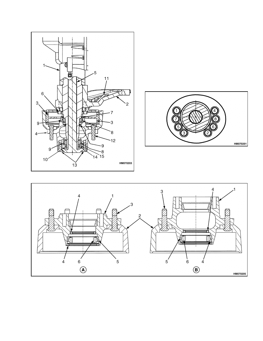
Figure 4. Drive Axle
Legend for Figure 4
1.
AXLE HOUSING
2.
AXLE MOUNT
3.
BRAKE SYSTEM
4.
HUB ASSEMBLY
5.
AXLE SHAFT
6.
DURALOCK BOLTS
7.
OIL SEAL
8.
BEARING CONE
9.
BEARING CUP
10. LOCK NUT -
WHEEL NUT
11. BRAKE HOSE
12. SERRATED BOLTS
13. AXLE SHAFT
BOLTS
14. LOCKWASHER
15. LOCK NUT -
WHEEL BEARINGS
Figure 5. Brake Assembly Torque Pattern
8.
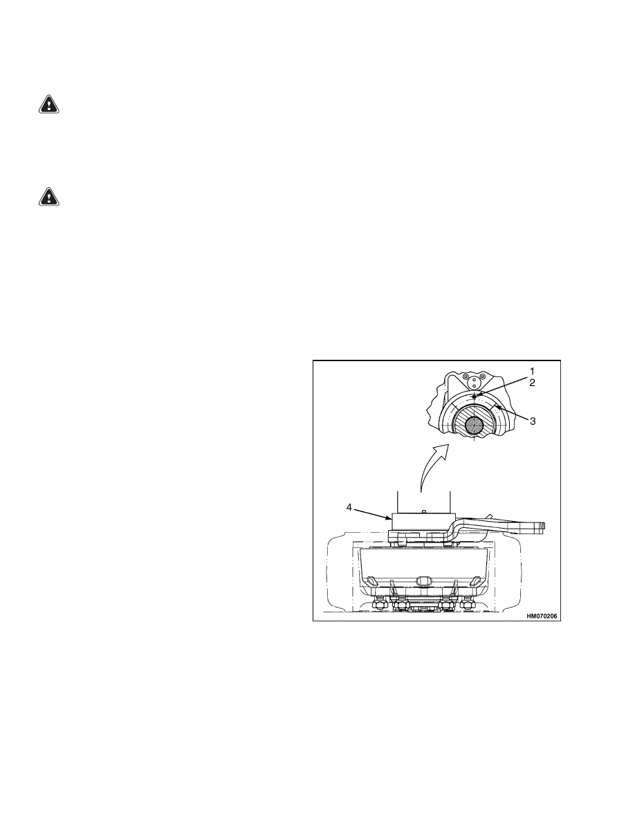
Pack wheel bearings with multipurpose grease.
9.
Install new oil seal in center of hub. See Figure 6.
Install inner bearing. Install inner seal in hub.
A. SHORT WHEEL BASE HUB ASSEMBLY
B. LONG WHEEL BASE HUB ASSEMBLY
1.
HUB
2.
BRAKE DRUM
3.
SERRATED HUB BOLT
4.
OIL SEAL
5.
ROLLER BEARING CUP
6.
ROLLER BEARING CONE
Figure 6. Hub Assembly
5
Torque Specifications
1400 SRM 984
10. Install hub onto drive axle. Use care not to dam-
age seals when installing hub.
11. Install outer bearing cone.
12. Install adjustment nut. Tighten nut to 205 N•m
(151 lbf ft) while rotating hub.
Loosen nut
until hub rotates freely.
The torque to rotate
wheel hub must be less than 25 N•m (18 lbf ft).
Retighten nut to 35 N•m (26 lbf ft) or to first
alignment position after 35 N•m (26 lbf ft). In-
stall lockwasher to hold nut. Install lock nut and
tighten it to 135 N•m (100 lbf ft).
13. Install brake drum onto drive axle.
CAUTION
When the wheels have been installed, check
all wheel nuts after 2 to 5 hours of opera-
tion. Torque nuts in a cross pattern to correct
torque value. When the nuts stay tight after
an 8-hour check, the interval for checking the
torque can be extended to 500 hours.
14. Install wheels.
Tighten wheel nuts to 610 to
680 N•m (450 to 502 lbf ft).
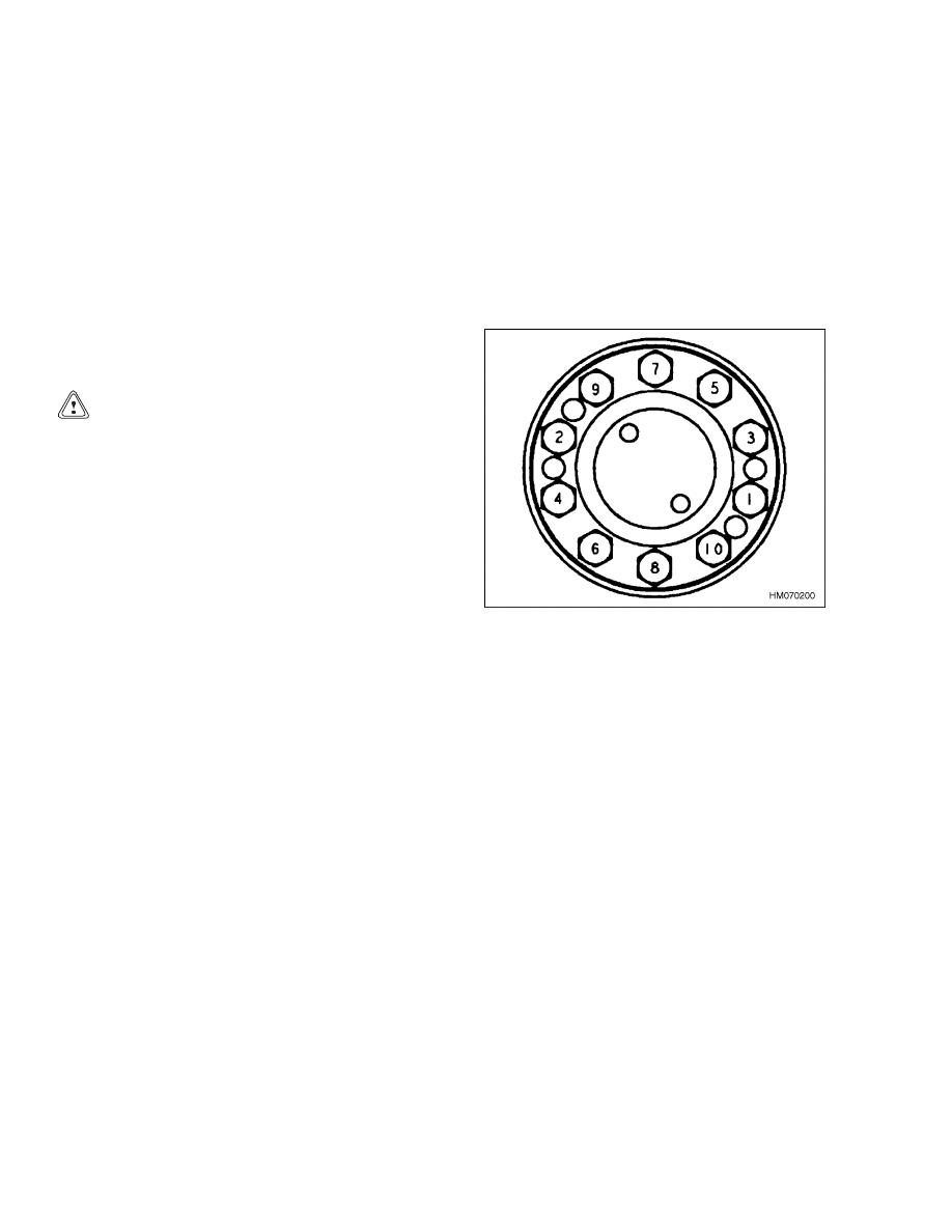
15. Apply sealant, Hyster Part No. 264159, to flange
of axle shaft. Install axle shaft. Tighten cap-
screws to 225 to 250 N•m (166 to 184 lbf ft), using
the sequence shown in Figure 7.
16. Install mast as described in the section Mast -
Description and Repair 4000 SRM 736. Fill
differential housing with 80W-90EP or 85W-140
gear lubricant through fill hole. Remove air from
brake system as described in the section Brake
System 1800 SRM 985.
Figure 7. Axle Shaft Torque Pattern
Torque Specifications
Brake Assembly to Axle Mounts
340 to 375 N•m (251 to 277 lbf ft)
Axle Mount to Frame
320 to 350 N•m (236 to 258 lbf ft)
Axle Shaft Flange Capscrews
225 to 250 N•m (166 to 184 lbf ft)
Axle Housing to Transmission Capscrews
65 N•m (48 lbf ft)
Wheel Nuts
610 to 680 N•m (450 to 502 lbf ft)
Hub Adjustment Nut
205 N•m (151 lbf ft) (Initial)
35 N•m (26 lbf ft) (Final)
6

1400 SRM 984
Troubleshooting
Troubleshooting
PROBLEM
POSSIBLE CAUSE
PROCEDURE OR ACTION
The lift truck will not move.
An axle shaft is broken.
Install new axle shaft.
The capscrews that hold the axle
shaft to the hub are broken.
Replace capscrews.
The differential is damaged.
Repair differential.
Pinion or ring gear is damaged.
Install new pinion and ring gear set.
The drive axle has leaks.
The drain or fill plug has damaged
threads, is loose, or is missing.
Repair threads. Tighten plug. Install
missing part.
The O-rings or seals have damage.
Install new O-rings and seals.
The drive axle housing is cracked.
Install new drive axle housing.
The drive axle makes noise.
The bearings have damage.
Install new parts.
The brake assembly is damaged.
Repair brake assembly.
The oil level is low.
Fill as required. Check for leaks.
The axle mounting capscrews are
loose.
Tighten
capscrews
to
specified
torque.
7

NOTES
____________________________________________________________
____________________________________________________________
____________________________________________________________
____________________________________________________________
____________________________________________________________
____________________________________________________________
____________________________________________________________
____________________________________________________________
____________________________________________________________
____________________________________________________________
____________________________________________________________
____________________________________________________________
____________________________________________________________
____________________________________________________________
____________________________________________________________
____________________________________________________________
____________________________________________________________
____________________________________________________________
____________________________________________________________
____________________________________________________________
8


TECHNICAL PUBLICATIONS
1400 SRM 984
9/03 (11/01) Printed in United Kingdom
Document Outline
Wyszukiwarka
Podobne podstrony:
1494953 1400SRM0944 (09 2003) UK EN
1498445 1400SRM0945 (09 2003) UK EN
897391 1400SRM0450 (09 2003) UK EN
910073 1400SRM0049 (09 2003) UK EN
1466247 1400SRM0731 (09 2003) UK EN
897394 1900SRM0453 (09 2003) UK EN
897987 1800SRM0659 (09 2003) UK EN
1494955 2000SRM0943 (09 2003) UK EN
897110 1900SRM0328 (09 2003) UK EN
897993 1600SRM0671 (09 2003) UK EN
897392 1600SRM0451 (09 2003) UK EN
1466235 1600SRM0733 (09 2003) UK EN
1466223 1900SRM0753 (09 2003) UK EN
więcej podobnych podstron