BRAKE SYSTEM
H14.00-20.00XM [A214];
H16.00-18.00XM-12EC (H400-450H-EC) [A214]
PART NO. 897987
1800 SRM 659

SAFETY PRECAUTIONS
MAINTENANCE AND REPAIR
• When lifting parts or assemblies, make sure all slings, chains, or cables are correctly
fastened, and that the load being lifted is balanced. Make sure the crane, cables, and
chains have the capacity to support the weight of the load.
• Do not lift heavy parts by hand, use a lifting mechanism.
• Wear safety glasses.
• DISCONNECT THE BATTERY CONNECTOR before doing any maintenance or repair
on electric lift trucks.
• Disconnect the battery ground cable on internal combustion lift trucks.
• Always use correct blocks to prevent the unit from rolling or falling. See HOW TO PUT
THE LIFT TRUCK ON BLOCKS in the Operating Manual or the Periodic Mainte-
nance section.
• Keep the unit clean and the working area clean and orderly.
• Use the correct tools for the job.
• Keep the tools clean and in good condition.
• Always use HYSTER APPROVED parts when making repairs. Replacement parts
must meet or exceed the specifications of the original equipment manufacturer.
• Make sure all nuts, bolts, snap rings, and other fastening devices are removed before
using force to remove parts.
• Always fasten a DO NOT OPERATE tag to the controls of the unit when making repairs,
or if the unit needs repairs.
• Be sure to follow the WARNING and CAUTION notes in the instructions.
• Gasoline, Liquid Petroleum Gas (LPG), Compressed Natural Gas (CNG), and Diesel fuel
are flammable. Be sure to follow the necessary safety precautions when handling these
fuels and when working on these fuel systems.
• Batteries generate flammable gas when they are being charged. Keep fire and sparks
away from the area. Make sure the area is well ventilated.
NOTE:
The following symbols and words indicate safety information in this
manual:
WARNING
Indicates a condition that can cause immediate death or injury!
CAUTION
Indicates a condition that can cause property damage!

Brake System
Table of Contents
TABLE OF CONTENTS
General ...............................................................................................................................................................
Description and Operation ................................................................................................................................
Parking Brake................................................................................................................................................
Brake Pedal Valves ........................................................................................................................................
Pilot Supply Valve Repair..................................................................................................................................
Repairs ...........................................................................................................................................................
Checks and Adjustments...............................................................................................................................
Accumulator Replacement.................................................................................................................................
Oil Cooler............................................................................................................................................................
Remove ...........................................................................................................................................................
Clean ..............................................................................................................................................................
Install .............................................................................................................................................................
Brake Pedal Components ..................................................................................................................................
Manifold .........................................................................................................................................................
Shuttle Valve..................................................................................................................................................
Remove and Disassemble..........................................................................................................................
Clean and Inspect......................................................................................................................................
Assemble and Install.................................................................................................................................
Brake Pedal Valves ........................................................................................................................................
Remove and Disassemble..........................................................................................................................
Clean and Inspect......................................................................................................................................
Assemble ....................................................................................................................................................
Install .........................................................................................................................................................
Parking Brake Valve Repair..............................................................................................................................
Remove ...........................................................................................................................................................
Install .............................................................................................................................................................
Parking Brake Caliper Repair ..........................................................................................................................
Brake System Air Removal ...............................................................................................................................
Service Brakes Air Removal .........................................................................................................................
Troubleshooting..................................................................................................................................................
Diagrams, Schematics, or Arrangements .........................................................................................................
Figure 9. Brake and Hydraulic System Schematic .................................................................................
This section is for the following models:
H14.00-20.00XM [A214];
H16.00-18.00XM-12EC (H400-450H-EC) [A214]
©2003 HYSTER COMPANY
i

"THE
QUALITY
KEEPERS"
HYSTER
APPROVED
PARTS

1800 SRM 659
Description and Operation
General
This section has the description and operation of the
hydraulic brake system. The section also has repair
procedures for components of the brake system. Also,
see the Hydraulic System 1900 SRM 666 for more
information on the hydraulic system. Disassembly
and assembly of the service brakes for repairs are de-
scribed in the Planetary Drive Axle 1400 SRM 657.
Disassembly and assembly of the parking brake for
repairs are described in Parking Brake 1800 SRM
1037. Disassembly and assembly of the accumulator
for repairs are described in Accumulator 1800 SRM
1036.
Description and Operation
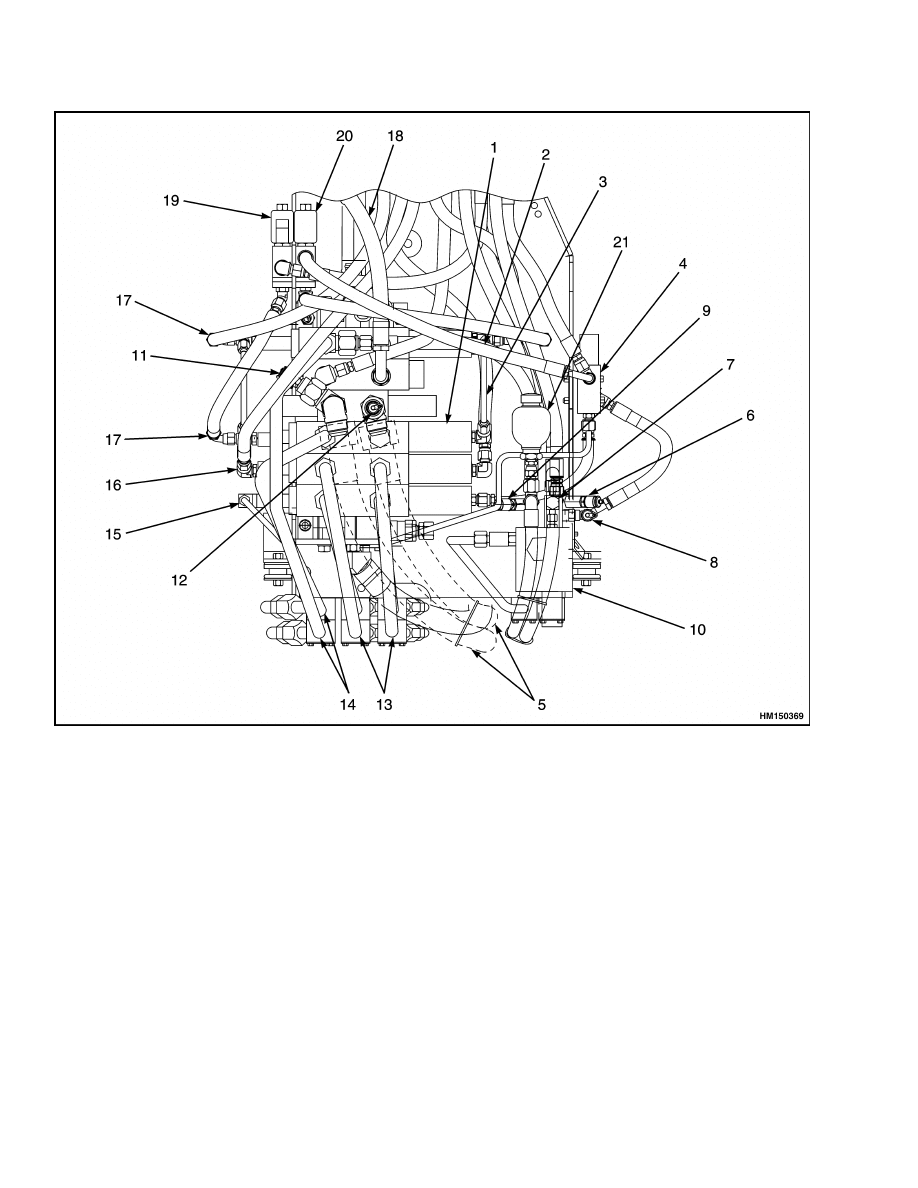
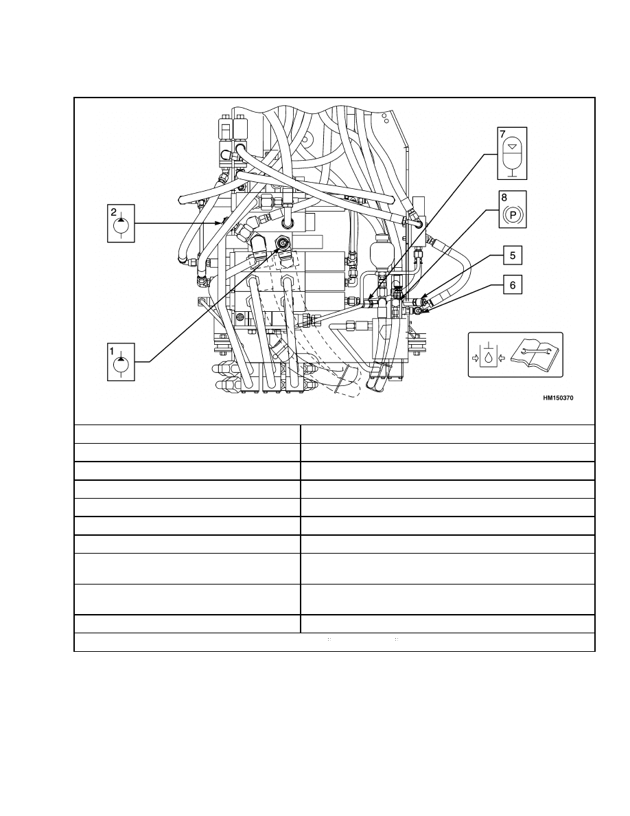
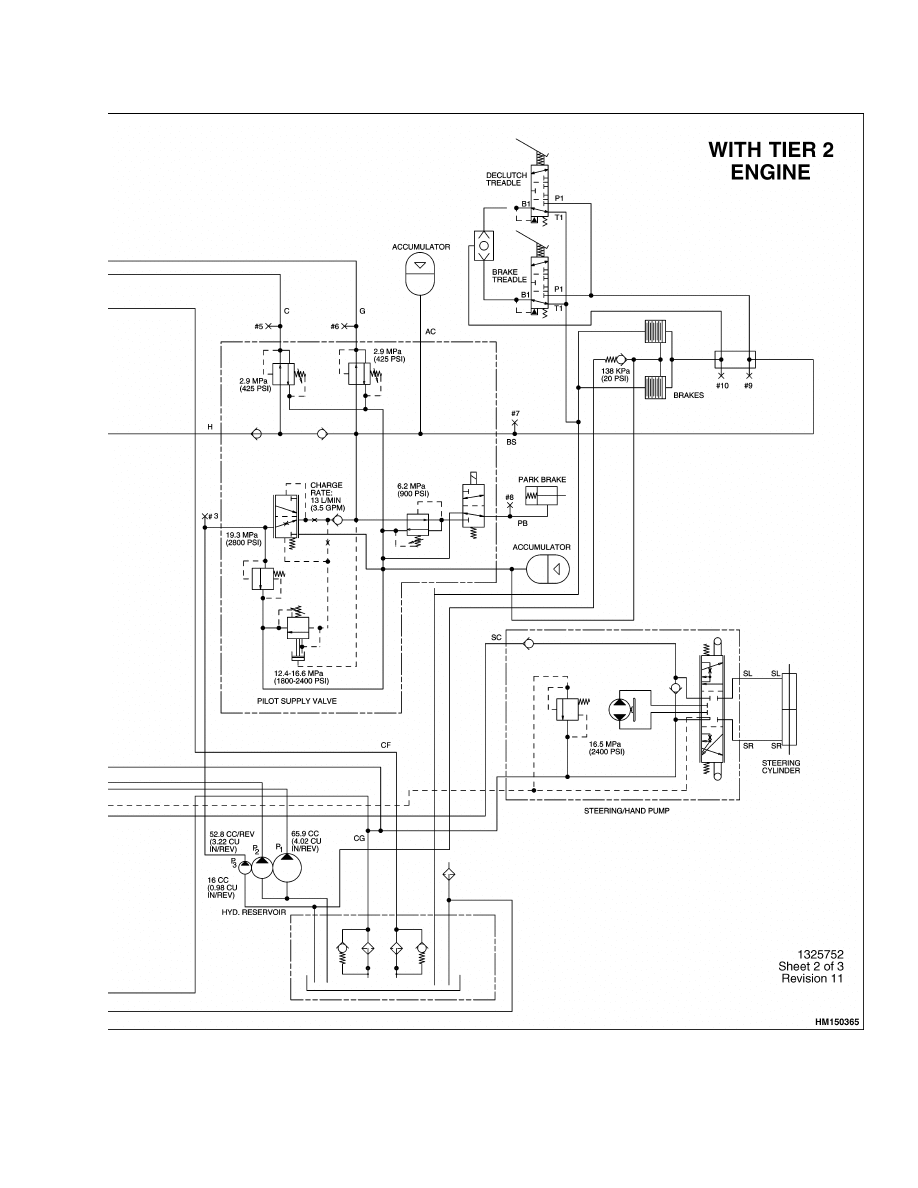
These lift trucks have a hydraulic brake system. See
Figure 9. The brake system uses the hydraulic fluid
and several components from the hydraulic system
of the lift truck. See Figure 1.
The small section of the hydraulic pump supplies the
oil to operate the brake system. Oil from the pump
goes to the pilot supply valve. The pilot supply valve
controls the flow of oil to the circuits for the following:
remote control valve, brake system, and the accumu-
lator. The pilot supply valve has a relief valve, three
check valves, a charging valve, an unloader valve,
and three pressure reduction valves. The solenoid
that operates the brake is also installed on the pilot
supply valve.
The charging valve in the pilot supply valve controls
the oil flow to the accumulator, the pressure reduc-
tion valves, and the brake pedal valves. The accumu-
lator stores oil under pressure to operate the brakes
when the engine is not running. A pressure reduc-
tion valve for the parking brake is set at 6.2 MPa
(900 psi). The service brake pedal controls the flow
of oil to the service brakes. The declutch/brake pedal
controls the flow of oil to the service brakes and the
declutch control at the transmission.
The charging valve and unloader valve work together
to supply hydraulic oil to the brake system and the
accumulator. The accumulator permits the operator
apply the brakes or lower the mast when the engine
is not running.
The charging valve has a spool and a check valve.
Hydraulic oil from the pump enters the charging
valve spool. A relief valve limits this oil pressure
to 19.3 MPa (2800 psi). Oil flows past the charging
valve spool to the accumulator and the pressure
reduction valves. The charging valve stops charg-
ing automatically when the accumulator pressure
reaches its high limit of 16.2 to 16.9 MPa (2350 to
2450 psi). When the accumulator pressure reaches
its low limit of 12.1 to 12.8 MPa (1750 to 1850 psi),
the unloader valve allows oil from the hydraulic
pump to charge the accumulator.
The service brakes are oil-cooled brakes and are
installed in housings in the drive axle. Within each
brake housing there are piston and friction discs
and separator plates. The separator plates do not
rotate because they have external teeth that fit in
the housing. The friction discs have internal teeth
that engage the axle and rotate with the hubs and
wheels.
When the brakes are applied, hydraulic
pressure moves the piston against the brake discs to
slow and stop the lift truck. There is an additional
circuit of hydraulic oil for cooling and lubricating the
brake discs.
1
Description and Operation
1800 SRM 659
1.
MAIN CONTROL VALVE
2.
RETURN TO TANK
3.
LIFT PILOT SUPPLY
4.
AUXILIARY CONTROL VALVE
5.
SUPPLY FROM PUMP
6.
CHECK PORT - LIFT PILOT PRESSURE
7.
CHECK PORT - PARKING BRAKE
8.
CHECK PORT - TILT PILOT PRESSURE
9.
CHECK PORT - ACCUMULATOR CHARGE
VALVE
10. PILOT SUPPLY VALVE
11. CHECK PORT - LIFT CIRCUIT/AUXILIARY
12. CHECK PORT - LIFT CIRCUIT/STEERING
13. TO TILT CYLINDERS
14. TO LIFT CYLINDERS
15. PILOT SUPPLY - AUXILIARY
16. PILOT SUPPLY - TILT
17. PILOT SUPPLY - LIFT
18. STEERING SUPPLY
19. LIFT INTERRUPT
20. LOWER INTERRUPT
21. ACCUMULATOR
Figure 1. Hydraulic System Components
2
1800 SRM 659
Description and Operation
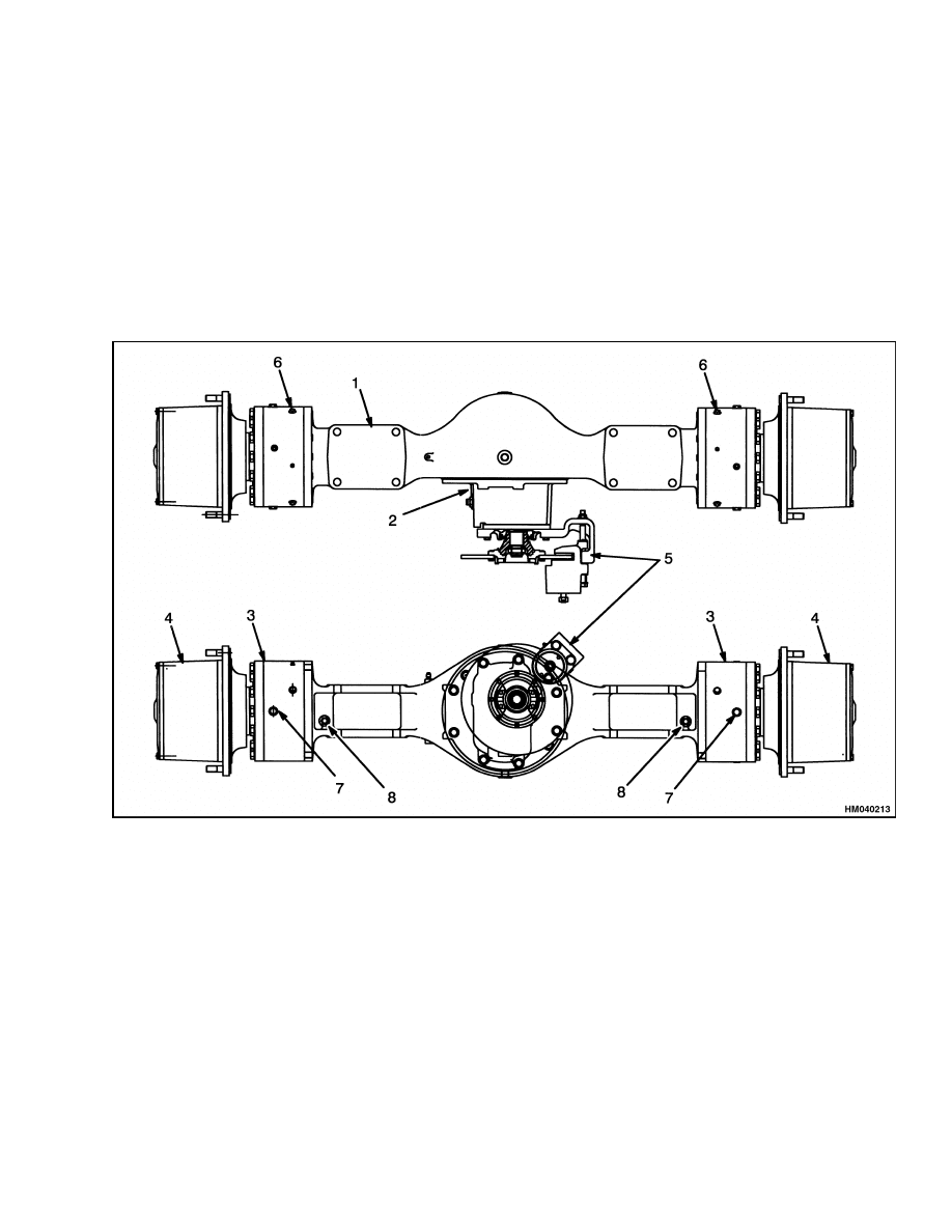
PARKING BRAKE
The parking brake uses a disc brake that is installed
on the differential housing.
The spring-applied
caliper is installed on the differential housing, while
the brake rotor is connected to the pinion shaft. See
Figure 2.
The operation of the parking brake is controlled by
the parking brake switch on the instrument panel.
Oil flow to the brake caliper is controlled by a so-
lenoid valve in the pilot supply valve. The parking
brake is applied when the knob on the parking brake
switch is pulled out. The parking brake is released
when the knob is pushed in.
When the knob is
pushed in, oil flows from a pressure reduction valve
through the solenoid valve to the brake caliper. The
oil pressure at the brake caliper acts against the
springs to release the brake.
The parking brake switch also illuminates the light
on the instrument panel when the parking brake is
applied.
1.
DRIVE AXLE HOUSING
2.
DIFFERENTIAL
3.
SERVICE BRAKES HOUSING
4.
PLANETARY GEAR HUB
5.
PARKING BRAKE
6.
SERVICE BRAKE ACTUATION INLET PORT
7.
BRAKE COOLING CIRCUIT INLET PORT
8.
BRAKE COOLING CIRCUIT OUTLET PORT
Figure 2. Planetary Drive Axle
3

Accumulator Replacement
1800 SRM 659
BRAKE PEDAL VALVES
The middle brake pedal operates only the service
brakes, while the left-hand (declutch/brake) pedal
operates the service brakes and the disengagement
of the transmission. See Figure 6. Both pedals can
energize the brake pressure switch on the manifold
to operate the stop lights.
When the middle brake pedal is depressed, hydraulic
oil flows through the pedal valve to the shuttle valve.
From the shuttle valve, oil flows to the piston for the
service brakes. The hydraulic pressure against the
piston applies the service brakes.
When the left-hand pedal (declutch/brake) is de-
pressed, hydraulic oil flows through the pedal valve
to the brake housing as described for the brake
pedal.
Slightly pushing the declutch/brake pedal
will apply the service brakes, and further pushing
the pedal will disengage the transmission.
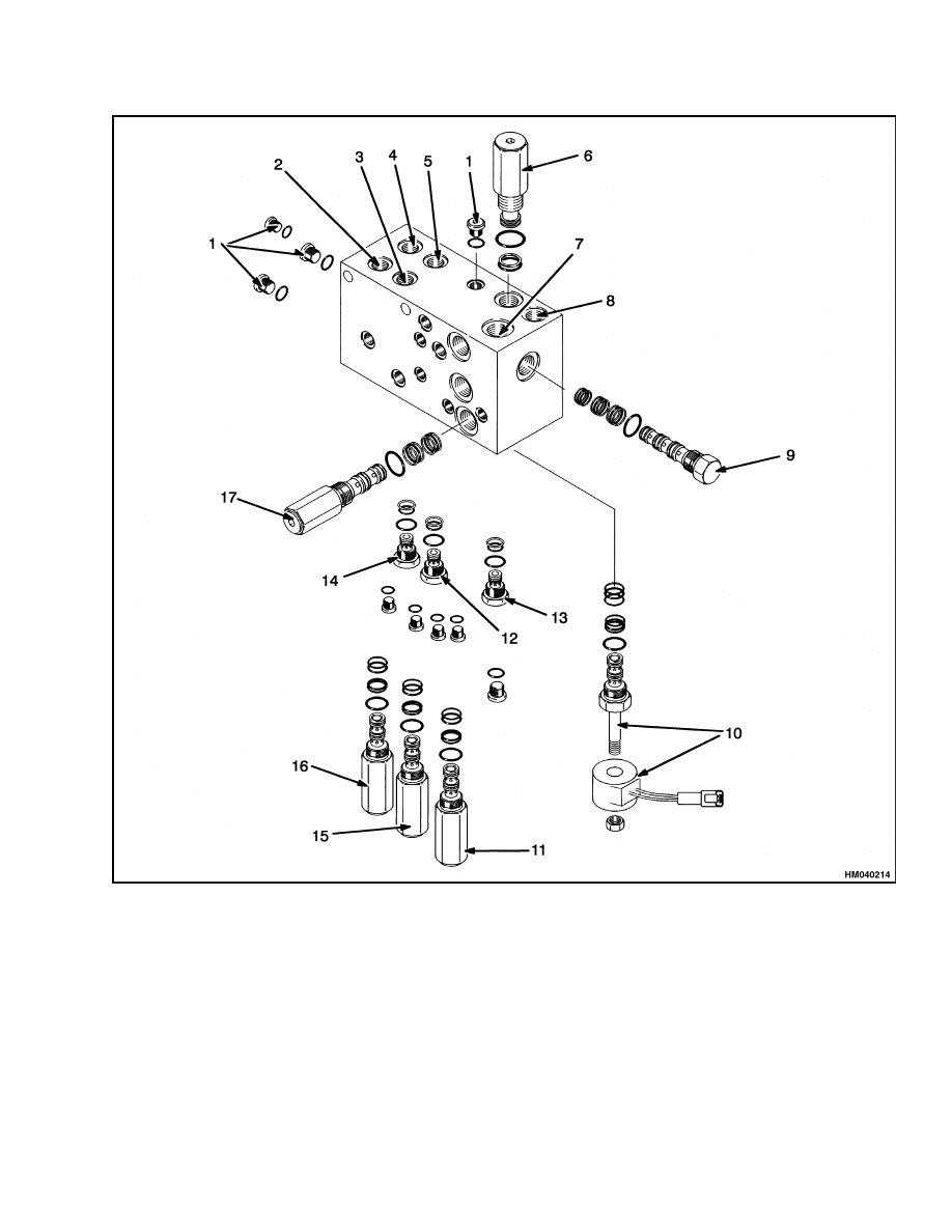
Pilot Supply Valve Repair
REPAIRS
NOTE: Information on the repair of the pilot supply
valve is in the section Hydraulic System 1900 SRM
666.
CHECKS AND ADJUSTMENTS
NOTE:
Information on the checks and adjustments of
the pilot supply valve are in the section Hydraulic
System 1900 SRM 666.
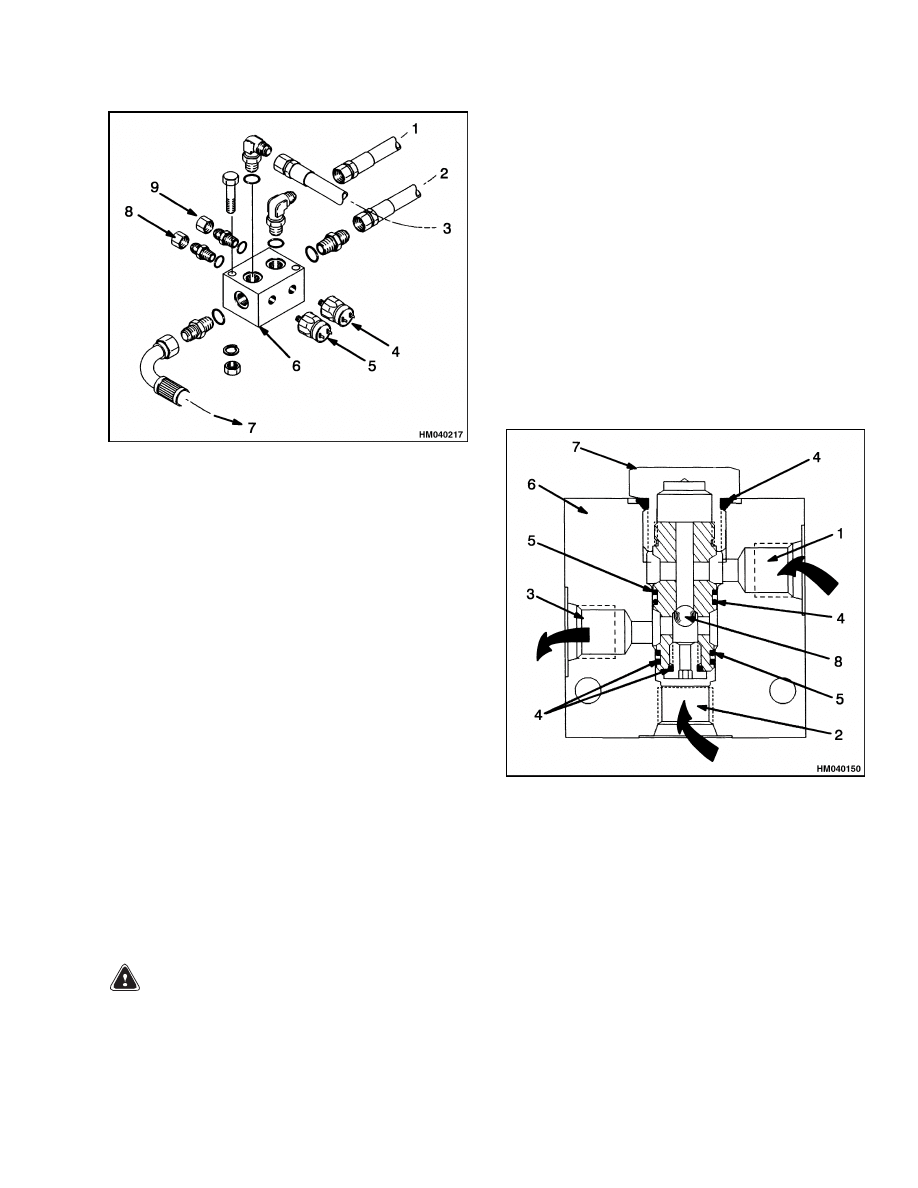
See Figure 3.
Accumulator Replacement
The accumulator is located inside the frame, near the
hydraulic system components, on the left-hand side
of the lift truck. If the accumulator does not charge
correctly or does not hold its charge, it must be re-
paired or replaced.
For repairs or replacement of the accumulator, see
Accumulator 1800 SRM 1036.
4
1800 SRM 659
Accumulator Replacement
1.
PLUG
2.
BRAKE SYSTEM SUPPLY
3.
FROM LIFT CIRCUIT
4.
PILOT PRESSURE FOR TILT
5.
PILOT SUPPLY FOR LIFT/LOWER
6.
RELIEF VALVE
7.
BRAKE SYSTEM COOLING SUPPLY
8.
PARKING BRAKE SUPPLY
9.
CHARGING VALVE
10. PARKING BRAKE SOLENOID
11. UNLOADER VALVE
12. LIFT CYLINDER CHECK VALVE
13. PARKING BRAKE CHECK VALVE
14. PILOT SUPPLY CHECK VALVE
15. PRESSURE REDUCTION VALVE LIFT CIRCUIT
16. PRESSURE REDUCTION VALVE TILT CIRCUIT
17. PRESSURE REDUCTION VALVE PARKING
BRAKE
Figure 3. Pilot Supply Valve
5

Brake Pedal Components
1800 SRM 659
Oil Cooler
WARNING
Never work under a raised carriage or forks.
Lower the carriage or use blocks and chains
on the mast weldments and carriage so they
cannot move. Make sure moving parts are at-
tached to a part that does not move. Before dis-
connecting any hydraulic connections, release
the accumulated pressure by applying brakes
8 to 10 times.
For the A214 ECH, the oil cooler is located on the
left-hand side of the frame, under the step to the cab.
For the A214 FLT, the oil cooler is located on the
right-hand side of the frame, under the step to the
cab.
REMOVE
1.
Lower the mast completely.
2.
Shut down the engine.
3.
Disconnect hydraulic lines and put tags on lines
for identification.
4.
Remove the four capscrews and washers that
hold the oil cooler to the frame.
5.
Remove oil cooler.
CLEAN
WARNING
Cleaning solvents can be flammable and toxic.
Cleaning solvents can also cause skin irrita-
tion. When using cleaning solvents, always fol-
low the solvent manufacturer’s recommended
safety precautions.
Compressed air can move particles so they
cause injury to the user or to other personnel.
Make sure compressed air path is away from
all personnel. Wear eye protection.
Clean all parts in solvent and dry the parts with com-
pressed air. Inspect the oil cooler for damage. Inspect
the parts of the oil cooler assembly for damage. Re-
place damaged parts.
INSTALL
1.
Position oil cooler.
2.
Install the four capscrews and washers that at-
tach oil cooler to the frame.
3.
Connect hydraulic lines.
4.
Start engine and check for leaks.
Brake Pedal Components
The components for the brake pedal and declutch
brake pedal are on and under the floor plate of the
operator’s compartment.
MANIFOLD
WARNING
Before disconnecting any hydraulic lines, re-
lease pressure from the hydraulic circuit as fol-
lows:
a. Stop the engine and completely lower the
carriage.
b. Operate the lift/lower lever and the brake
pedals until the hydraulic pressure is re-
leased.
The manifold has two test ports and two pressure
switches. There are no parts that can be repaired in
the manifold. The pressure switches can be replaced
if they are damaged. See Figure 4.
6
1800 SRM 659
Brake Pedal Components
1.
FROM SHUTTLE VALVE
2.
FROM PILOT VALVE
3.
FROM BRAKE PEDAL VALVE
4.
ACCUMULATOR PRESSURE SWITCH
5.
BRAKE LIGHT PRESSURE SWITCH
6.
MANIFOLD
7.
TO FRONT MANIFOLD FOR SERVICE BRAKES
8.
BRAKE PRESSURE TEST PORT
9.
ACCUMULATOR PRESSURE TEST PORT
Figure 4. Manifold
SHUTTLE VALVE
Remove and Disassemble
1.
The shuttle valve is installed under the floor
plate between the brake valve and the de-
clutch/brake valve. See Figure 5. Put tags for
identification on the lines. Disconnect the lines
from the valve. Put caps on the open lines.
2.
Remove the shuttle valve from the frame.
3.
Remove the shuttle cartridge from the valve
body.
Remove the O-rings and backup rings.
Do not disassemble the cartridge. If it does not
operate correctly, replace it.
Clean and Inspect
WARNING
Cleaning solvents can be flammable and toxic
and can cause skin irritation.
When using
cleaning solvents, always follow the solvent
manufacturer’s recommended safety precau-
tions.
Clean the parts in solvent. Lubricate the parts with
clean hydraulic oil for assembly.
Assemble and Install
1.
Install new backup rings and O-rings on the car-
tridge. Install the cartridge in the valve body.
Tighten the cartridge to 34 to 41 N•m (25 to
30 lbf ft). See Figure 5.
2.
Install the valve on the frame. Connect the lines
to the valve.
3.
Operate the system and check the valve for leaks.
1.
FROM DECLUTCH/BRAKE PEDAL
2.
FROM SERVICE BRAKE PEDAL
3.
TO BRAKE CALIPERS AND RELAY VALVE
4.
O-RING
5.
BACKUP RING
6.
VALVE BODY
7.
CARTRIDGE
8.
BALL
Figure 5. Shuttle Valve
7

Brake Pedal Components
1800 SRM 659
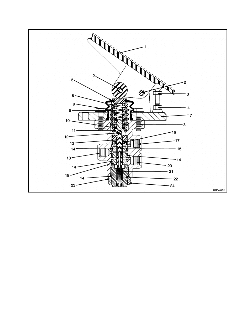
BRAKE PEDAL VALVES
Remove and Disassemble
WARNING
Before disconnecting any hydraulic lines, re-
lease pressure from the hydraulic circuit as fol-
lows:
a. Stop the engine and completely lower the
carriage.
b. Operate the lift/lower lever and the brake
pedals until the hydraulic pressure is re-
leased.
1.
Put tags for identification on the lines. Discon-
nect the lines from the brake pedal valve. See
Figure 6. Put caps on the open lines. Remove
the pedal assembly from the floor plate.
2.
Remove a snap ring and the pin from the pedal.
3.
Remove the capscrews that hold the valve body
to the base plate. Carefully pull the valve body
from the base. There are two compressed springs
at the top of the valve.
4.
Remove the piston and boot from the pedal. Re-
move the springs.
5.
Remove the shims, ball retainer, and ball from
the valve body.
6.
Remove the nut and washer from the end plug.
Remove the end plug, spring, and spool. Remove
and discard the O-rings and cup seal from the
sleeve.
7.
Remove the sleeve and spacer.
Clean and Inspect
WARNING
Cleaning solvents can be flammable and toxic
and can cause skin irritation.
When using
cleaning solvents, always follow the solvent
manufacturer’s recommended safety precau-
tions.
Clean the parts in solvent. Inspect the spool and
bores for scratches. If there are scratches or other
damage, the parts must be replaced. Lubricate the
parts with clean hydraulic oil for assembly.
Assemble
1.
Install new O-rings and seals on the parts. See
Figure 6. Make sure the cup seal is installed so
that the open side is toward the bottom of the
pedal.
2.
Install the piston assemblies in the housing.
3.
Install the springs, retainers, and the inner
housing. Install the pedal assembly.
Install
1.
Install the brake pedal valve to the floor plate.
2.
Connect the lines to the valve.
3.
Check the brake pedal valve for leaks.
8
1800 SRM 659
Brake Pedal Components
1.
PEDAL
2.
PIN
3.
CAPSCREW
4.
NUT
5.
RUBBER BOOT
6.
SPRING
7.
BASE PLATE
8.
BUSHING
9.
PISTON
10. SHIM(S)
11. BALL RETAINER
12. BALL
13. SPACER
14. O-RING
15. SPOOL
16. CUP SEAL
17. TO DRAIN CIRCUIT
18. TO SERVICE BRAKES
19. SLEEVE
20. INLET
21. SPRING
22. END PLUG
23. WASHER
24. NUT
Figure 6. Brake and Declutch/Brake Pedal Valve
9

Brake System Air Removal
1800 SRM 659
Parking Brake Valve Repair
The operation of the parking brake is controlled by
the parking brake switch on the instrument panel.
Oil flow to the brake caliper is controlled by a sole-
noid valve in the pilot supply valve. See Figure 3.
The parking brake valve has two parts that can be
replaced if they are damaged: the valve assembly
and the solenoid. These parts cannot normally be
repaired. The valve can be removed from the pilot
supply valve to repair a seal.
REMOVE
WARNING
Before disconnecting any hydraulic lines, re-
lease pressure from the hydraulic circuit as fol-
lows:
a. Stop the engine and completely lower the
carriage.
b. Operate the lift/lower lever and the brake
pedals until the hydraulic pressure is re-
leased.
1.
Disconnect the control wire at the plug for the
solenoid.
2.
Remove the nut that fastens the solenoid to the
valve stem.
3.
Use a wrench to remove the valve from the pilot
supply valve.
INSTALL
1.
Use a new seal kit to replace the seals in the
valve.
2.
Install the valve in the pilot supply valve.
3.
Install the solenoid on the valve stem and con-
nect the plug for the control wires.
4.
Operate the system and check for leaks and cor-
rect operation of the parking brake system.
Parking Brake Caliper Repair
For repairs and replacement of the parking brake
caliper, see Parking Brake 1800 SRM 1037.
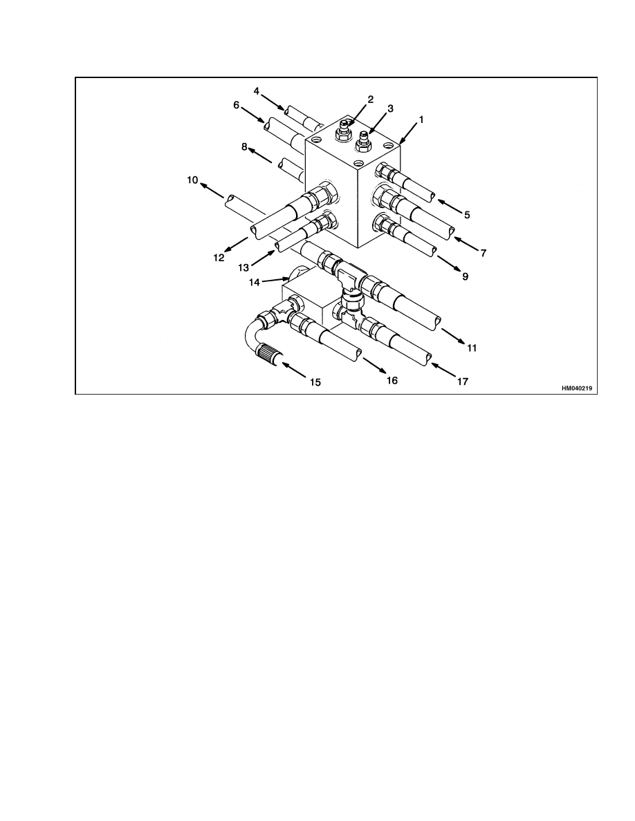
Brake System Air Removal
SERVICE BRAKES AIR REMOVAL
There is a manifold and check valve fastened to the
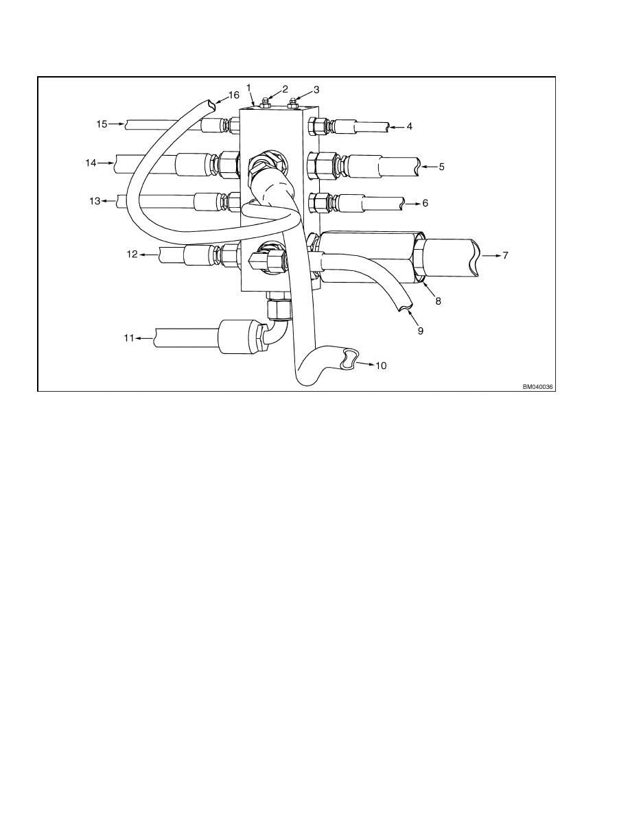
front crossmember of the frame. See Figure 7 and
Figure 8. A hydraulic line is installed from each ser-
vice brake housing to the manifold. A special fitting
for each brake is installed on top of the manifold.
Connect one end of a hose to the special fitting. Put
the other end of the hose to drain into a container.
Start the engine and apply the brakes. This action
pushes air from the brake system. Tighten the spe-
cial fitting when the air has been removed. Repeat
this step for the other brake assembly.
NOTE: Most of the air is removed from the brake sys-
tem when the engine is started and the brakes actu-
ated. This procedure makes sure that the remainder
of the air is removed from the brake lines.
10
1800 SRM 659
Brake System Air Removal
1.
MANIFOLD
2.
SPECIAL FITTING FOR LEFT BRAKE (VENT
NIPPLE)
3.
SPECIAL FITTING FOR RIGHT BRAKE (VENT
NIPPLE)
4.
HOSE TO REMOVE AIR FROM LEFT BRAKE
5.
HOSE TO REMOVE AIR FROM RIGHT BRAKE
6.
LEFT HYDRAULIC OIL RETURN HOSE
7.
RIGHT HYDRAULIC OIL RETURN HOSE
8.
BRAKE PRESSURE TO LEFT BRAKE
9.
BRAKE PRESSURE TO RIGHT BRAKE
10. HYDRAULIC OIL COOLING TO LEFT BRAKE
11. HYDRAULIC OIL COOLING TO RIGHT BRAKE
12. HYDRAULIC OIL RETURN TO HYDRAULIC TANK
13. BRAKE PRESSURE FROM BRAKE VALVES
14. CHECK VALVE
15. DRAIN FROM BRAKE VALVES TO HYDRAULIC
TANK
16. DRAIN TO HYDRAULIC TANK
17. HYDRAULIC OIL COOLING SUPPLY FROM
RADIATOR HEAT EXCHANGER
Figure 7. Manifold and Check Valve (Tier 1)
11
Brake System Air Removal
1800 SRM 659
1.
MANIFOLD
2.
SPECIAL FITTING FOR LEFT BRAKE (VENT
NIPPLE)
3.
SPECIAL FITTING FOR RIGHT BRAKE (VENT
NIPPLE)
4.
HOSE TO REMOVE AIR FROM RIGHT BRAKE
5.
RIGHT HYDRAULIC OIL COOLING RETURN
HOSE
6.
BRAKE PRESSURE TO RIGHT BRAKE
7.
TO HYDRAULIC TANK
8.
CHECK VALVE 138 kPa (20 psi)
9.
HYDRAULIC OIL COOLING SUPPLY
10. HYDRAULIC OIL RETURN TO HYDRAULIC TANK
11. HYDRAULIC OIL COOLING TO RIGHT BRAKE
12. HYDRAULIC OIL COOLING TO LEFT BRAKE
13. BRAKE PRESSURE TO LEFT BRAKE
14. LEFT HYDRAULIC OIL COOLING RETURN
HOSE
15. HOSE TO REMOVE AIR FROM LEFT BRAKE
16. FROM SHUTTLE VALVE
Figure 8. Manifold and Check Valve (Tier 2)
12
1800 SRM 659
Brake System Air Removal
Table 1. Hydraulic System Check Ports
Label for Hydraulic System Check Ports
Check Port
Specification
No. 1 - Lift System Relief
23.8 to 24.5 MPa (3450 to 3550 psi) @ full throttle
No. 1 - Tilt/Aux System Relief
18.6 to 19.3 MPa (2700 to 2800 psi) @ full throttle
No. 2 - Lift System Relief
23.8 to 24.5 MPa (3450 to 3550 psi) @ full throttle
No. 2 - Steering System Relief
16.2 to 16.9 MPa (2350 to 2450 psi) @ full throttle
No. 5 - Lift System Pilot Pressure
2.8 to 3.1 MPa (400 to 450 psi) @ idle speed
No. 6 - Tilt/Auxiliary Pilot Pressure
2.8 to 3.1 MPa (400 to 450 psi) @ idle speed
No. 7 - Accumulator Charge Valve (Low)
Pressure
12.1 to 12.8 MPa (1750 to 1850 psi) @ idle speed
No. 7 - Accumulator Charge Valve (High)
Pressure
16.2 to 16.9 MPa (2350 to 2450 psi) @ idle speed
No. 8 - Parking Brake Pressure
6.0 to 6.4 MPa (875 to 925 psi) @ idle speed
Make sure oil is at operating temperature - 54 to 66 C (129 to 150 F).
13

Troubleshooting
1800 SRM 659
Troubleshooting
PROBLEM
POSSIBLE CAUSE
PROCEDURE OR ACTION
The brakes do not stop the
lift truck.
Brake discs are worn or damaged.
Replace worn or damaged parts.
There is not enough hydraulic pres-
sure in the system.
Check brake system pressure and ad-
just or repair.
The accumulator charge valve or ac-
cumulator is damaged.
Repair the fault in the accumulator
circuit or replace the accumulator.
The brake pedal valve has a malfunc-
tion.
Repair the brake pedal valve.
The shuttle valve does not operate
correctly.
Repair or replace the shuttle valve.
The brakes apply slowly.
There is not enough hydraulic pres-
sure in the system.
Check brake system pressure and ad-
just or repair.
The hydraulic lines have a leak or re-
striction.
Check for leaks or replace damaged
lines.
The brake pedal valve(s) is damaged.
Check for correct operation and re-
pair.
Brake pedal goes to the floor.
There is air in the hydraulic system.
Remove air from hydraulic system.
There is a leak(s) in a hydraulic line.
Check and repair hydraulic line(s).
Brakes
do
not
operate
equally.
Brake discs are worn or damaged.
Replace damaged parts.
The brake line to one of the brake
housings has a restriction.
Check and repair hydraulic line.
The brakes do not release.
Brake lines have a restriction.
Check and repair hydraulic line(s).
The brake pedal valve is damaged.
Check for correct operation and re-
pair.
One
of
the
brake
pedal
valves does not operate the
brakes.
The shuttle valve does not operate.
Check for correct operation and re-
pair.
14

1800 SRM 659
Troubleshooting
PROBLEM
POSSIBLE CAUSE
PROCEDURE OR ACTION
Service brakes do not oper-
ate when the engine is not
running.
There is no charge in the accumula-
tor.
Check pressure and repair.
Hydraulic lines for the accumulator
circuit leak or have restrictions.
Check and repair hydraulic line(s).
The parking brake does not
release.
The hydraulic pressure is too low.
Check pressure and adjust or repair
pressure reduction valve.
There is a leak in the hydraulic line.
Check and repair hydraulic line(s).
The parking brake solenoid does not
operate.
Replace the solenoid.
The parking brake caliper does not
move on the bracket.
Repair caliper so that it moves freely.
The parking brake will not
apply.
The springs in the brake caliper are
damaged.
Repair caliper.
The brake pads are worn or dam-
aged.
Replace brake pads.
The brake rotor is worn or damaged.
Replace brake rotor.
Accumulator
does
not
charge.
No gas charge in accumulator.
Replace accumulator.
Charging valve does not operate cor-
rectly.
Replace charging valve spool in pilot
valve housing.
Leak in hydraulic line to accumula-
tor.
Repair leak.
No output from hydraulic pump.
Check hydraulic pump for correct
output and pressure.
Accumulator starts to charge
but does not reach the high
limit.
Relief valve does not operate cor-
rectly.
Check relief valve for correct opera-
tion. Replace a worn valve spool.
Charging valve does not operate cor-
rectly.
Replace charging valve spool in pilot
valve housing.
A brake valve is worn or damaged
(leaks).
Repair a worn brake valve that leaks.
15

Diagrams, Schematics, or Arrangements
1800 SRM 659
PROBLEM
POSSIBLE CAUSE
PROCEDURE OR ACTION
Accumulator starts to charge
but does not reach the high
limit. (Cont.)
Low output from hydraulic pump.
Repair or replace a worn hydraulic
pump.
Accumulator charging cycles
repeat when system is not
being used.
Leak in charging valve.
Replace charging valve spool in pilot
valve housing.
Accumulator charging time
is too long.
Charging valve does not operate cor-
rectly.
Replace charging valve spool in pilot
valve housing.
A brake valve is worn or damaged
(leaks).
Repair a worn brake valve that leaks.
Low output from hydraulic pump.
Repair or replace a worn hydraulic
pump.
16

NOTES
____________________________________________________________
____________________________________________________________
____________________________________________________________
____________________________________________________________
____________________________________________________________
____________________________________________________________
____________________________________________________________
____________________________________________________________
____________________________________________________________
____________________________________________________________
____________________________________________________________
____________________________________________________________
____________________________________________________________
____________________________________________________________
____________________________________________________________
____________________________________________________________
____________________________________________________________
____________________________________________________________
____________________________________________________________
____________________________________________________________
17
Diagrams, Schematics, or Arrangements
1800 SRM 659
18
1800 SRM 659
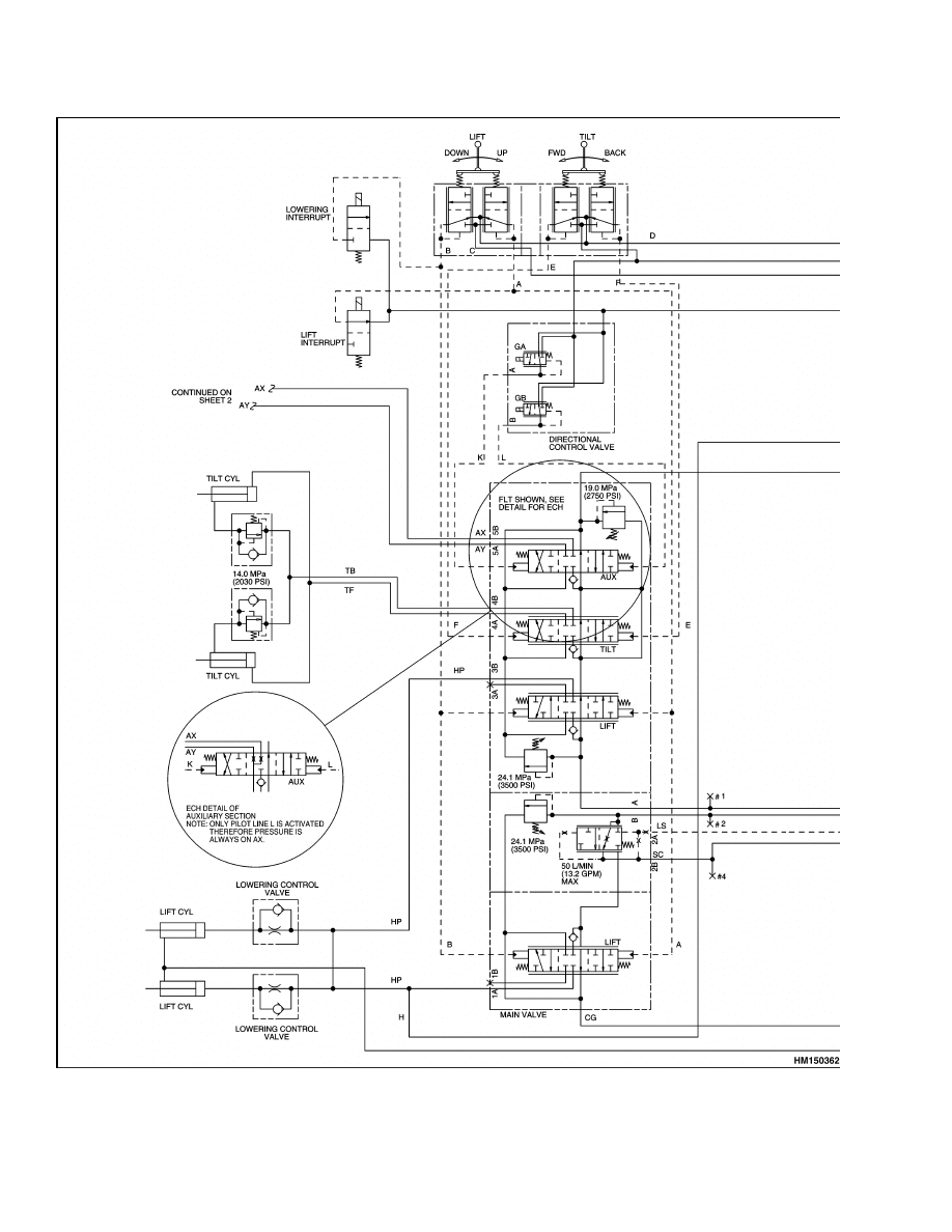
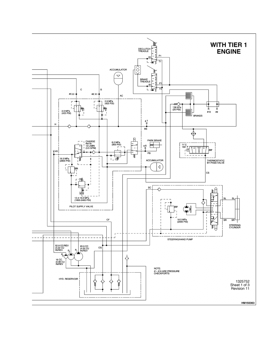
Diagrams, Schematics, or Arrangements
Figure 9. Brake and Hydraulic System Schematic (Sheet 1 of 2)
19
Diagrams, Schematics, or Arrangements
1800 SRM 659
20
1800 SRM 659
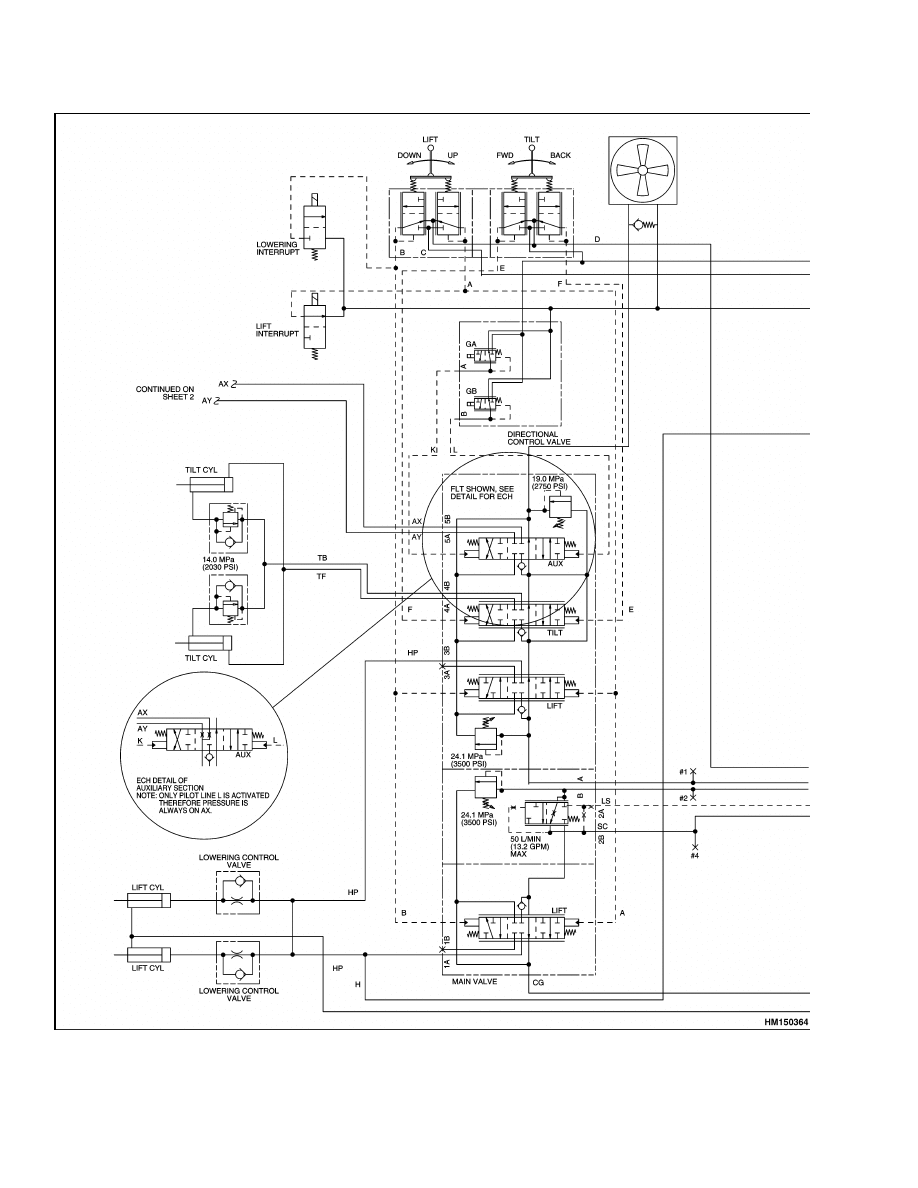
Diagrams, Schematics, or Arrangements
Figure 9. Brake and Hydraulic System Schematic (Sheet 2 of 2)
21

NOTES
____________________________________________________________
____________________________________________________________
____________________________________________________________
____________________________________________________________
____________________________________________________________
____________________________________________________________
____________________________________________________________
____________________________________________________________
____________________________________________________________
____________________________________________________________
____________________________________________________________
____________________________________________________________
____________________________________________________________
____________________________________________________________
____________________________________________________________
____________________________________________________________
____________________________________________________________
____________________________________________________________
____________________________________________________________
____________________________________________________________
22


TECHNICAL PUBLICATIONS
1800 SRM 659
9/03 (5/97) Printed in United Kingdom
Document Outline
- toc
- tables
Wyszukiwarka
Podobne podstrony:
897109 1800SRM0327 (09 2003) UK EN
1494953 1400SRM0944 (09 2003) UK EN
897394 1900SRM0453 (09 2003) UK EN
1498445 1400SRM0945 (09 2003) UK EN
1510463 1400SRM0984 (09 2003) UK EN
1494141 1800SRM0937 (12 2003) UK EN
1475871 1800SRM0785 (11 2003) UK EN
1494955 2000SRM0943 (09 2003) UK EN
897110 1900SRM0328 (09 2003) UK EN
897993 1600SRM0671 (09 2003) UK EN
897391 1400SRM0450 (09 2003) UK EN
897392 1600SRM0451 (09 2003) UK EN
1466235 1600SRM0733 (09 2003) UK EN
910073 1400SRM0049 (09 2003) UK EN
1466247 1400SRM0731 (09 2003) UK EN
1466223 1900SRM0753 (09 2003) UK EN
897113 8000SRM0331 (09 2003) UK EN
więcej podobnych podstron