PLANETARY DRIVE
AXLE
(DRY SYSTEM)
H8.00-12.00XM (H170-280HD) [F007, G007];
H13.00-16.00XM (H300-360HD) [E019, F019];
H10.00XM-12EC (H360HD-EC) [E019, F019]
PART NO. 1498445
1400 SRM 945

SAFETY PRECAUTIONS
MAINTENANCE AND REPAIR
• When lifting parts or assemblies, make sure all slings, chains, or cables are correctly
fastened, and that the load being lifted is balanced. Make sure the crane, cables, and
chains have the capacity to support the weight of the load.
• Do not lift heavy parts by hand, use a lifting mechanism.
• Wear safety glasses.
• DISCONNECT THE BATTERY CONNECTOR before doing any maintenance or repair
on electric lift trucks.
• Disconnect the battery ground cable on internal combustion lift trucks.
• Always use correct blocks to prevent the unit from rolling or falling. See HOW TO PUT
THE LIFT TRUCK ON BLOCKS in the Operating Manual or the Periodic Mainte-
nance section.
• Keep the unit clean and the working area clean and orderly.
• Use the correct tools for the job.
• Keep the tools clean and in good condition.
• Always use HYSTER APPROVED parts when making repairs. Replacement parts
must meet or exceed the specifications of the original equipment manufacturer.
• Make sure all nuts, bolts, snap rings, and other fastening devices are removed before
using force to remove parts.
• Always fasten a DO NOT OPERATE tag to the controls of the unit when making repairs,
or if the unit needs repairs.
• Be sure to follow the WARNING and CAUTION notes in the instructions.
• Gasoline, Liquid Petroleum Gas (LPG), Compressed Natural Gas (CNG), and Diesel fuel
are flammable. Be sure to follow the necessary safety precautions when handling these
fuels and when working on these fuel systems.
• Batteries generate flammable gas when they are being charged. Keep fire and sparks
away from the area. Make sure the area is well ventilated.
NOTE:
The following symbols and words indicate safety information in this
manual:
WARNING
Indicates a condition that can cause immediate death or injury!
CAUTION
Indicates a condition that can cause property damage!

Planetary Drive Axle
Table of Contents
TABLE OF CONTENTS
General ...............................................................................................................................................................
Description .........................................................................................................................................................
Operation............................................................................................................................................................
Identification..................................................................................................................................................
Removal ..............................................................................................................................................................
Disassembly........................................................................................................................................................
Brake Drum ...................................................................................................................................................
Planetary Spider and Gearing Assembly H8.00-12.00XM (H170-280HD).................................................
Dry Brakes .....................................................................................................................................................
Planetary Spider and Gearing Assembly H13.00-16.00XM (H300-360HD) and H10.00XM-12EC
(H360HD-EC).................................................................................................................................................
Spindle and Brake Spider .............................................................................................................................
Cleaning..............................................................................................................................................................
Ground or Polished Parts ..............................................................................................................................
Parts With Rough Finish...............................................................................................................................
Axle Assemblies .............................................................................................................................................
Drying Cleaned Parts ....................................................................................................................................
Corrosion Prevention .........................................................................................................................................
Parts Inspection .................................................................................................................................................
Tapered Roller Bearings................................................................................................................................
Bevel Pinion and Ring Gear Sets..................................................................................................................
Main Differential Assembly ..........................................................................................................................
Axle Shafts .....................................................................................................................................................
Yoke ................................................................................................................................................................
Brakes ............................................................................................................................................................
Repair or Replace Parts.................................................................................................................................
Repair Welding ..............................................................................................................................................
Apply Silicone Gasket Material ....................................................................................................................
Assembly.............................................................................................................................................................
Spindle, Brake Spider, and Brake ................................................................................................................
Wheel End ......................................................................................................................................................
Adjust Wheel Bearing Preload......................................................................................................................
Planetary Spider and Gearing Assembly H8.00-12.00XM (H170-280HD).................................................
Planetary Spider and Gearing Assembly H13.00-16.00XM (H300-360HD) and H10.00XM-12EC
(H360HD-EC).................................................................................................................................................
Planetary Spider Assembly...........................................................................................................................
Installation .........................................................................................................................................................
Torque Specifications .........................................................................................................................................
Lubrication Specification...................................................................................................................................
This section is for the following models:
H8.00-12.00XM (H170-280HD) [F007, G007];
H13.00-16.00XM (H300-360HD) [E019, F019];
H10.00XM-12EC (H360HD-EC) [E019, F019]
©2003 HYSTER COMPANY
i

"THE
QUALITY
KEEPERS"
HYSTER
APPROVED
PARTS
1400 SRM 945
Description
General
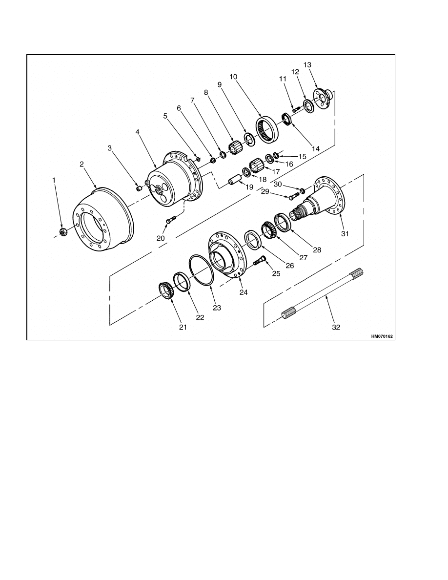
This section has a description and the repair procedures for the planetary gear axle.
Description
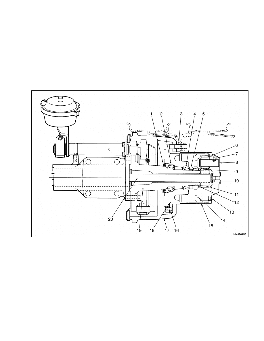
The planetary axles incorporate a single reduction
carrier/differential assembly with hypoid gearing.
The final reduction is a planetary spur designed
gearing built into the wheel hubs. See Figure 1 and
Figure 2. The axles have only cast housings. See
Figure 3 and the section Differential for your lift
truck.
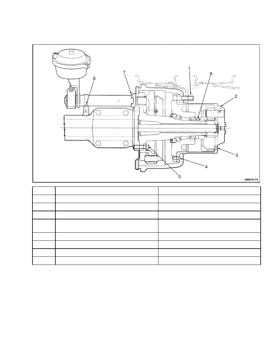
1.
OIL SEAL
2.
INNER BEARING
3.
WHEEL STUD
4.
OUTER BEARING
5.
LOCK NUT
6.
PLANETARY GEAR
7.
SETSCREW
8.
PLANETARY PINION SHAFT
9.
PIN
10. THRUST BUTTON
11. SUN GEAR
12. SUN GEAR THRUST WASHER
13. MAGNETIC DRAIN PLUG
14. RING GEAR
15. PLANETARY SPIDER
16. MACHINE SCREW
17. BRAKE DRUM
18. O-RING
19. SPINDLE
20. AXLE SHAFT
Figure 1. Wheel End Cross Section H8.00-12.00XM (H170-280HD)
1
Description
1400 SRM 945
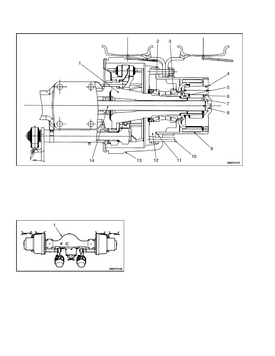
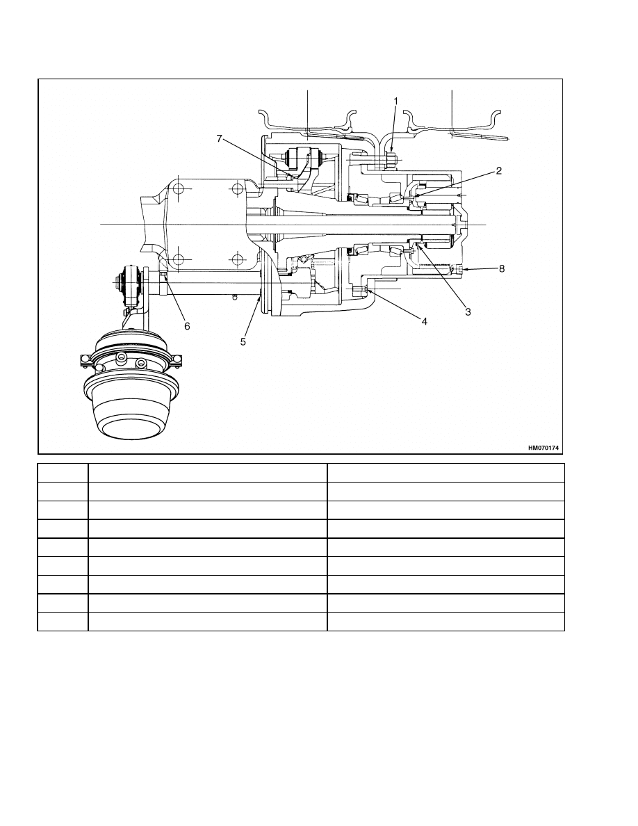
1.
SPINDLE
2.
INNER BEARING
3.
OUTER BEARING
4.
O-RING
5.
ADJUSTING NUT
6.
PLANETARY PINION GEAR
7.
SUN GEAR
8.
THRUST BUTTON
9.
PLANETARY SPIDER
10. WHEEL STUD
11. WHEEL HUB O-RING
12. HUB
13. BRAKE DRUM
14. AXLE SHAFT
Figure 2. Wheel End Cross Section H13.00-16.00XM (H300-360HD) and H10.00-XM-12EC
(H360HD-EC)
1.
PLANETARY DRIVE AXLE HOUSING
Figure 3. Planetary Drive Axle
2
1400 SRM 945
Operation
Operation
The planetary axles permit the hypoid gearing of the
carrier and the axle shafts to carry only a nominal
torsional load. At the same time, they provide the
highest practical numerical gear reduction at the
wheels.
• The hypoid pinion and differential assembly of the
first reduction supports the roller bearings.
• A hardened precision spacer between the inner and
outer pinion bearings adjusts and maintains the
pinion bearing preload.
• The positioning of the threaded adjusting rings in
the carrier leg and cap bores adjusts and maintains
the differential tapered bearing preload.
• The teeth of the floating sun gear mesh with the
teeth of the planetary spur gears.
• The planetary gears rotate on planetary shafts that
are mounted on a spider. The planetary gear teeth
in turn mesh with the teeth of the floating ring
gear.
• The hypoid gear set in the carrier transmits power
to the axle shafts and the sun gear of the final
reduction, through the revolving planetary gears,
and into the planetary spider.
• The planetary wheel ends on the H8.00-12.00XM
(H170-280HD), H13.00-16.00XM (H300-360HD),
and H10.00XM-12EC (H360HD-EC) are serviced
almost identically for cam or wet disc brakes.
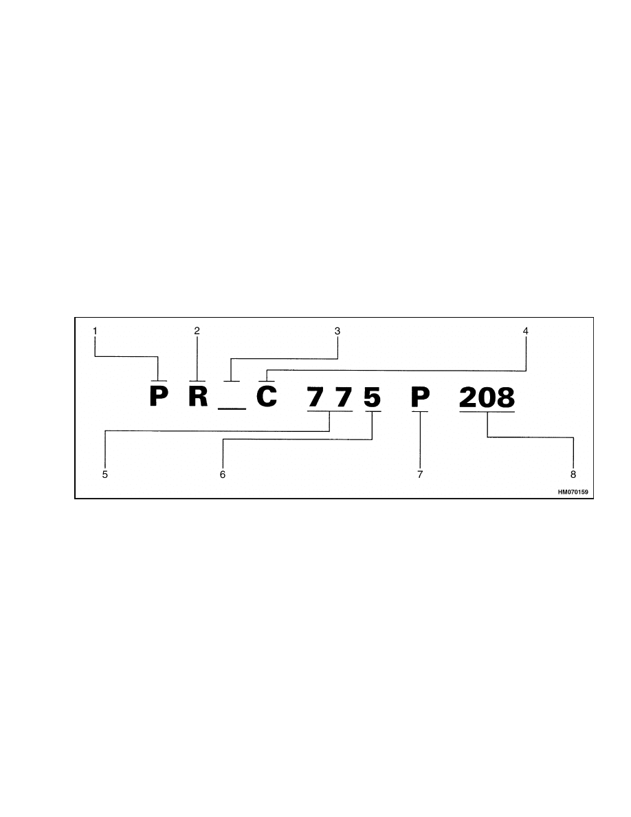
IDENTIFICATION
NOTE: The exact axle model specification tag is lo-
cated on the axle housing. See Figure 4.
1.
P - PLANETARY
2.
R - RIGID
3.
L - MOUNTING OTHER THAN PAD WITH
DRILLING (ONLY IF APPLICABLE)
4.
C - INTEGRAL CAST (HOUSING TYPE
DESIGNATION)
5.
WHEEL END DESIGNATION (BASIC MODEL
NUMBER) FIRST TWO OR THREE DIGITS
6.
CARRIER DESIGNATION FOR BASE MODEL
NUMBER (LAST DIGIT)
7.
BRAKE TYPE
N - NONE
P - DRY BRAKES
8.
EXACT SPECIFICATION
Figure 4. Planetary Drive Axle Identification
3
Disassembly
1400 SRM 945
Removal
NOTE:
The planetary assemblies can be removed
with the drive axle installed in the lift truck. If the
drive axle must be removed, do the following steps.
If the drive axle will not be removed, do only Step 1
and Step 2, then the Disassembly procedures.
1.
Put blocks under lift truck frame to raise drive
wheels from ground. See "How to Put Lift Truck
on Blocks" in the Operating Manual or Peri-
odic Maintenance for your lift truck.
2.
Remove mast assembly from lift truck as de-
scribed in the section Mast 4000 SRM 445 or
4000 SRM 1062.
3.
Remove air chambers as described in the section
Dry Brake System 1800 SRM 937.
4.
Drain lubricant from axle as described in the sec-
tion Periodic Maintenance for your lift truck.
5.
Disconnect drive shaft from drive axle.
6.
Remove wheels. See Disassembly, Step 1 and
Step 2.
WARNING
Verify that the lifting device has the capacity
to lift axle assembly and components.
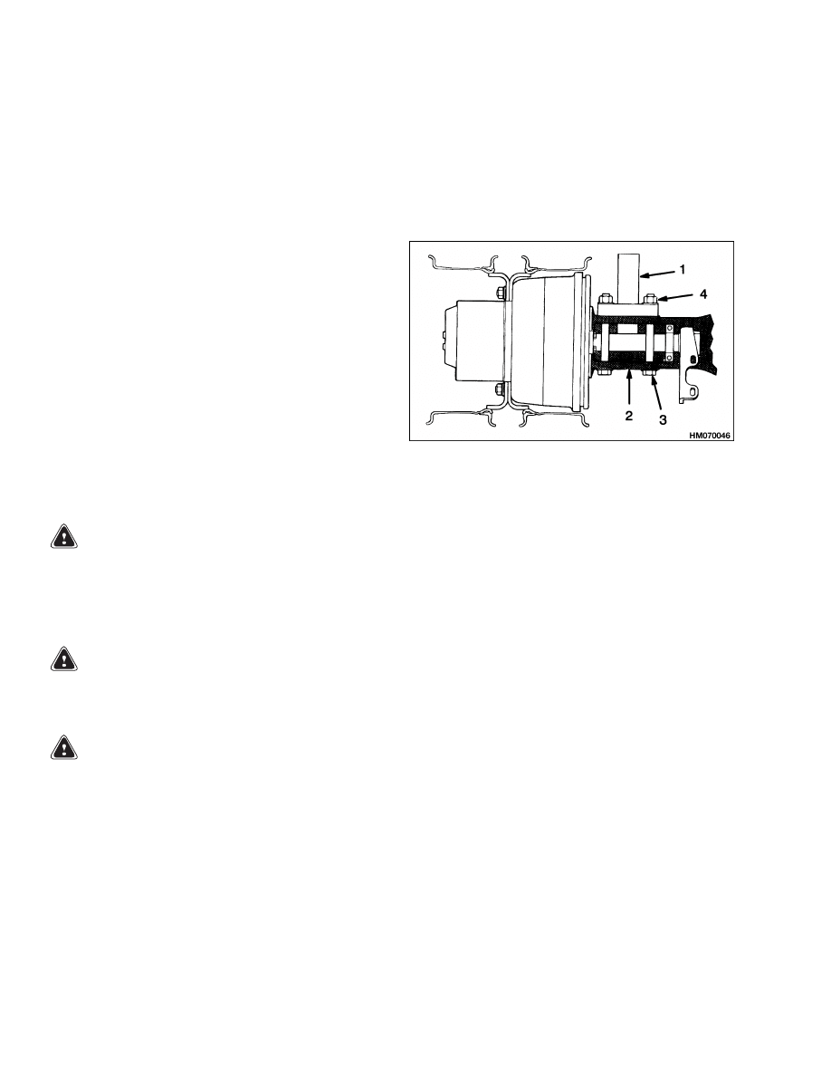
7.
Use a lifting device (floor jack or forks of a lift
truck) to remove drive axle. Put lifting device
under axle to give it support. Remove bolts and
nuts that hold axle to frame. See Figure 5. Re-
move drive axle from lift truck frame. Clean all
parts in solvent and dry with compressed air.
1.
LIFT TRUCK
FRAME
2.
AXLE HOUSING
3.
BOLT
4.
NUT
Figure 5. Axle Mount
Disassembly
WARNING
To prevent serious eye injury, always wear eye
protection when performing vehicle mainte-
nance or service.
WARNING
Completely remove air pressure from tires
before removing wheels from lift truck.
Air
pressure in the tires can cause the tire and
rim parts to explode, causing serious injury or
death.
1.
Put blocks under lift truck frame to raise drive
wheels from ground. See Removal, Step 1. Raise
axle to remove weight from tires, so tires are still
touching floor. Loosen wheel nuts just enough
so they can be easily removed. Remove air from
tires. Remove valve core to make sure all air
is out of inner tube. Push a wire through valve
stem to make sure that valve stem does not have
a restriction.
2.
Raise axle so tires and wheels can be removed.
Remove wheel nuts. Use a tire jack to remove
tires and wheels.
BRAKE DRUM
1.
Rotate wheel ends so magnetic drain plug in
planetary spider is at the bottom. Remove plug.
Drain and discard lubricant from both wheel
ends. See Figure 1.
2.
If necessary, remove magnetic drain plug from
bottom of axle housing. Drain and discard lubri-
cant from carrier center section.
3.
Adjust brake slack adjuster to retract brake
shoes to produce clearance between lining and
brake drum.
4
1400 SRM 945
Disassembly
WARNING
To prevent serious personal injury and pos-
sible damage to components, be very careful
when using lifting devices during service and
maintenance procedures.
• Inspect to make sure that neither lifting
strap is damaged.
• Do not subject lifting straps to any shock or
drop loading.
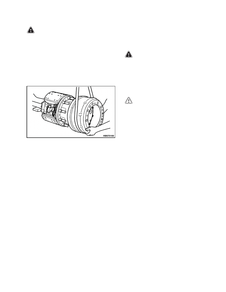
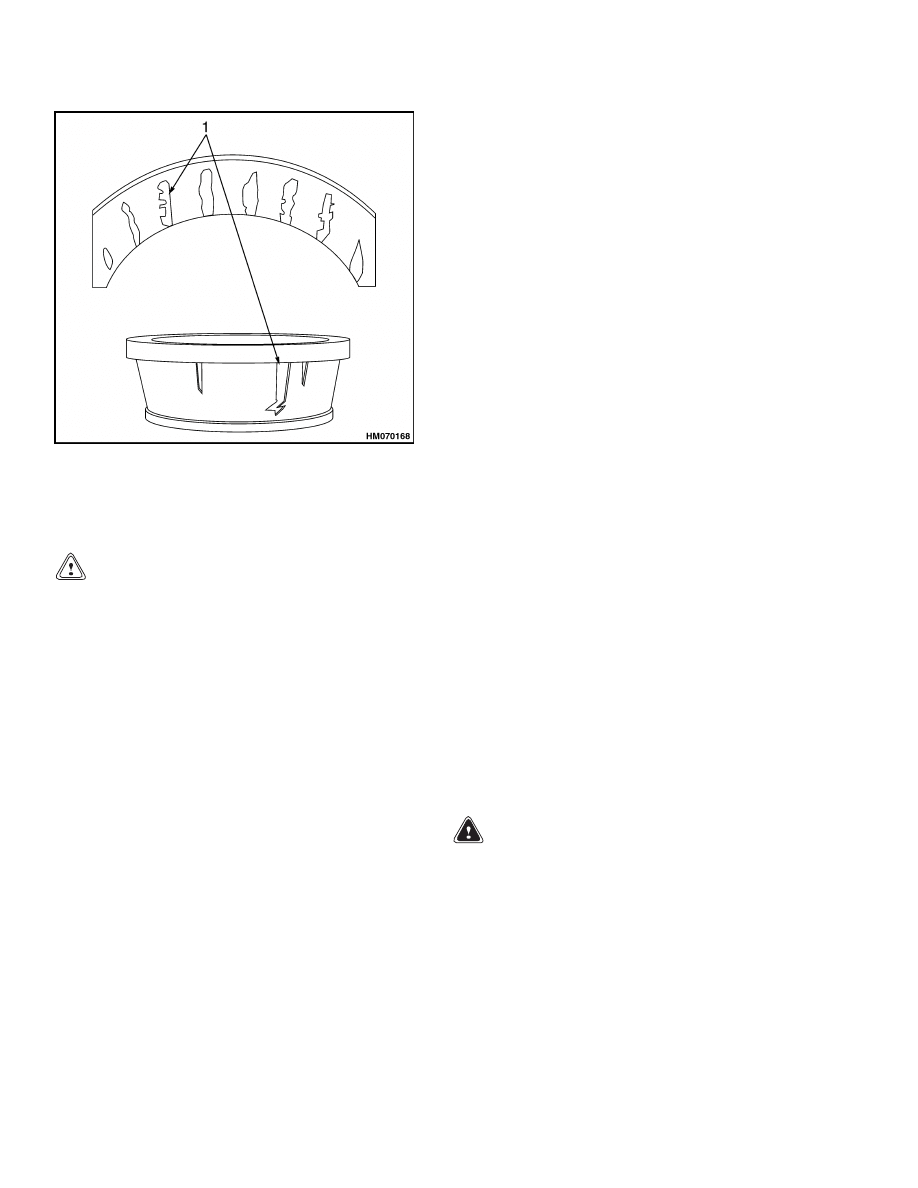
4.
Use a lifting device to support brake drum. See
Figure 6.
Figure 6. Wheel End Assembly
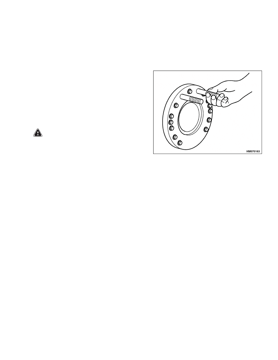
5.
Install capscrews into threaded holes in brake
drum.
Gradually tighten capscrews in equal
amounts to push drum off pilot surface of plane-
tary spider. See Figure 1 and Figure 2.
6.
With lifting device, carefully remove brake drum.
See Figure 6.
7.
Remove five slotted head machine screws that
attach planetary spider to wheel hub.
PLANETARY SPIDER AND GEARING
ASSEMBLY H8.00-12.00XM (H170-280HD)
NOTE:
If only the planetary pinions are removed for
inspection without removing the pinion shaft, pro-
ceed to Step 5. See Figure 7.
1.
With a lifting device, remove planetary spider
from wheel hub. Set its large flange side on work-
bench.
2.
Matchmark outer ends of pinion shafts and plan-
etary spider to aid in reassembly if original pin-
ion shafts are used.
3.
Remove setscrew from each pinion shafts.
WARNING
Observe all warnings and cautions provided
by the press manufacturer to avoid damage to
components and serious personal injury.
Use a brass or leather mallet for assembly and
disassembly procedures. Do not hit steel parts
with a steel hammer. Pieces of a part can break
off and cause serious personal injury.
CAUTION
To avoid damage to the pinion shaft, provide a
soft cushioned area to receive the pinion shaft
when it is removed from the spider.
4.
Use a press to remove pinion shafts. If a press
is not available, use a brass drift and mallet to
drive out shaft. Press or drive pinion shaft out
toward large flange end of planetary spider.
5.
Remove snap ring, inner thrust washer, plane-
tary pinion, and outer thrust washer from each
pinion shaft.
6.
Remove axle shaft thrust button only if it is worn.
Press it out TOWARD large end of planetary spi-
der.
NOTE:
The sun gear thrust washer may come out
with the axle shaft and sun gear assembly.
7.
Remove axle shaft, planetary sun gear, and snap
ring assembly.
8.
If necessary, remove snap ring from axle shaft to
allow for removal of sun gear and sun gear thrust
washer.
9.
If necessary, remove sun gear thrust washer from
end of planetary ring gear.
10. Remove planetary ring gear.
11. Remove wheel bearing adjusting nut.
5
Disassembly
1400 SRM 945
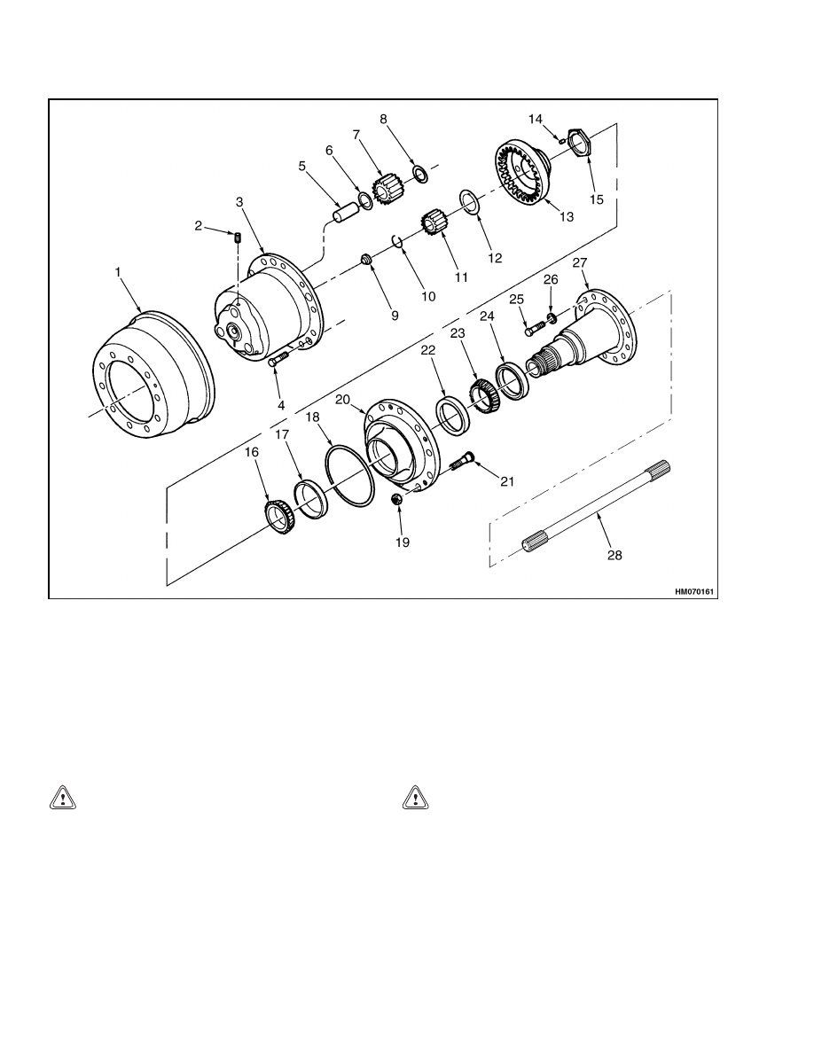
1.
BRAKE DRUM
2.
SETSCREW
3.
PLANETARY SPIDER
4.
MACHINE SCREW
5.
PINION SHAFT
6.
OUTER THRUST WASHER
7.
PLANETARY PINION
8.
INNER THRUST WASHER
9.
THRUST BUTTON
10. SNAP RING
11. PLANETARY SUN GEAR
12. THRUST WASHER
13. PLANETARY RING GEAR
14. ADJUSTING NUT DOWEL PIN
15. ADJUSTING NUT
16. OUTER BEARING CONE
17. OUTER BEARING CUP
18. O-RING
19. WHEEL NUT
20. HUB
21. WHEEL STUD
22. INNER BEARING CUP
23. INNER BEARING CONE
24. OIL SEAL ASSEMBLY
25. CAPSCREW
26. WASHER
27. SPINDLE
28. SHAFT
Figure 7. Hub and Shaft Assembly H8.00-12.00XM (H170-280HD)
CAUTION
The outer bearing cone will be loose as you pass
it over the end of the spindle. Hold cone se-
curely to avoid dropping it and damaging cone.
12. Remove wheel hub assembly.
Wheel bearings
and oil seal will come off with wheel hub.
NOTE: If replacing the hub oil seal and bearings,
continue with Step 13 through Step 16.
CAUTION
Do not damage hub oil seal bore surface in
wheel hub. Damage to this surface will result
in oil leakage after assembly.
13. Remove wheel hub oil seal from wheel hub.
14. Remove inner bearing cone.
15. Press out outer bearing cup and inner bearing
cup from hub.
6
1400 SRM 945
Disassembly
16. Remove and discard O-ring from wheel hub.
DRY BRAKES
NOTE:
To
disassemble
the
H8.00-12.00XM
(H170-280HD),
H13.00-16.00XM
(H300-360HD),
and H10.00XM-12EC (H360HD-EC) dry brakes, see
Dry Brake System 1800 SRM 937.
NOTE: If it is necessary to remove the anchor pins,
remove brake dust shields for convenient access to
anchor pins.
PLANETARY SPIDER AND GEARING
ASSEMBLY H13.00-16.00XM (H300-360HD)
AND H10.00XM-12EC (H360HD-EC)
WARNING
To prevent serious personal injury and pos-
sible damage to components, be very careful
when using lifting devices during service and
maintenance procedures.
• Inspect to make sure that neither lifting
strap is damaged.
• Do not subject lifting straps to any shock or
drop loading.
1.
With a lifting device, remove planetary spider as-
sembly from wheel hub and set it on workbench.
Rest spider on its large flange end.
2.
If the planetary ring gear did not remain with the
planetary spider assembly during the assembly’s
removal, remove ring gear from planetary ring
gear hub. See Figure 8.
3.
Mark large ends of planetary pinion shafts and
planetary spider to aid in reassembly if original
pinion shafts are used.
4.
Place planetary spider assembly on blocks with
large flange end facing UP. Remove snap ring
from each pinion shaft.
WARNING
Observe all warnings and cautions provided
by the press manufacturer to avoid damage to
components and serious personal injury.
Use a brass or leather mallet for assembly and
disassembly procedures. Do not hit steel parts
with a steel hammer. Pieces of a part can break
off and cause serious personal injury.
CAUTION
To avoid damage to the pinion shaft, provide
a soft cushioned area to receive pinion shaft
when it is removed from spider.
5.
Use a press to remove pinion shafts out of spider.
If a press is not available, use a brass drift and
mallet to drive out shaft. Press or drive pinion
shaft out toward small end of spider which faces
DOWN.
6.
Remove planetary pinions and thrust washers
from planetary spider.
7.
If the axle shaft thrust button and/or ring gear
support thrust buttons are worn and require re-
placement, place planetary spider on blocks with
large flange end facing DOWN. Press them out
toward large end of planetary spider.
8.
Remove axle shaft, planetary sun gear, and snap
ring assembly.
NOTE:
The sun gear thrust washer may come out
with the axle shaft and sun gear assembly.
9.
Remove snap ring from axle shaft to allow re-
moval of sun gear from axle shaft.
10. If necessary, remove sun gear thrust washer from
axle shaft.
11. If necessary, remove sun gear thrust washer from
end of spindle.
12. Remove two lock plate capscrews. Remove lock
plate from planetary ring gear hub.
13. Remove wheel bearing adjusting nut.
14. Remove planetary ring gear hub. Outer wheel
bearing cone will remain on ring gear hub. If it
is damaged, remove it from hub.
15. Remove wheel hub. Hub oil seal and inner bear-
ing assembly will remain in hub.
CAUTION
Do not damage hub oil seal bore surface in
wheel hub. Damage to this surface will result
in oil leakage after assembly.
16. Remove hub oil seal.
7
Disassembly
1400 SRM 945
1.
WHEEL NUT
2.
BRAKE DRUM
3.
MAGNETIC DRAIN FILL PLUG
4.
PLANETARY SPIDER
5.
THRUST BUTTON
6.
THRUST BUTTON
7.
SNAP RING
8.
PLANETARY SUN GEAR
9.
THRUST WASHER
10. PLANETARY RING GEAR
11. CAPSCREW
12. LOCK
13. PLANETARY RING GEAR HUB
14. ADJUSTING NUT
15. LOCK RING
16. INNER THRUST WASHER
17. PLANETARY PINION
18. OUTER THRUST WASHER
19. PINION SHAFT W/O-RING
20. MACHINE SCREW
21. OUTER BEARING CONE
22. OUTER BEARING CUP
23. O-RING
24. HUB
25. WHEEL STUD
26. INNER BEARING CUP
27. INNER BEARING CONE
28. OIL SEAL ASSEMBLY
29. CAPSCREW
30. FLAT WASHER
31. SPINDLE
32. SHAFT
Figure 8. Hub and Shaft Assembly H13.00-16.00XM (H300-360HD) and H10.00XM-12EC
(H360HD-EC)
8
1400 SRM 945
Disassembly
17. Remove inner bearing cone.
18. If replacement of wheel bearings is necessary,
press out outer bearing cup and inner bearing
cup.
19. Remove and discard O-ring from wheel hub.
NOTE:
To
disassemble
the
H8.00-12.00XM
(H170-280HD),
H13.00-16.00XM
(H300-360HD),
and H10.00XM-12EC (H360HD-EC) dry brakes, see
Dry Brake System 1800 SRM 937.
NOTE: If it is necessary to remove the anchor pins,
remove brake dust shields for convenient access to
anchor pins.
SPINDLE AND BRAKE SPIDER
WARNING
To prevent serious personal injury and pos-
sible damage to components, be very careful
when using lifting devices during service and
maintenance procedures.
• Inspect to make sure that neither lifting
strap is damaged.
• Do not subject lifting loops or lifting straps to
any shock or drop loading.
NOTE:
Removal of the capscrews allows the spindle
and brake assembly to separate. They can fall from
the planetary axle housing and cause damage to com-
ponents and serious personal injury.
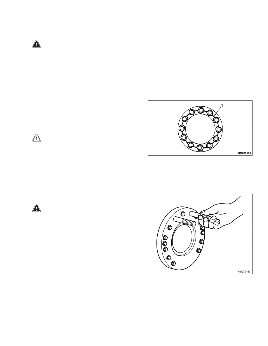
1.
To prevent the spindle and the brake spider from
falling after all the mounting capscrews are re-
moved, use one of the following procedures.
a. Use a lifting device to support spindle during
disassembly.
b. Remove only two capscrews. Replace them
with two temporary M16 × 2.0 thread studs
102 mm (4 in.) before remaining capscrews
are removed. See Figure 9.
• Install one stud at eleven o’clock position.
• Install one stud at one o’clock position.
Figure 9. Spindle and Brake Spider Studs
2.
Remove two capscrews and washers that mount
clamp around brake camshaft housing tube to
axle housing.
3.
Remove capscrews and washers that mount
brake spider and spindle to axle housing.
4.
Remove brake spider and air chamber assembly
from spindle.
5.
Remove spindle from axle housing. If necessary,
tap lightly on spindle to loosen pilot fit and to
overcome adhesion due to cured gasket material
in flange joint.
9
Corrosion Prevention
1400 SRM 945
Cleaning
GROUND OR POLISHED PARTS
WARNING
To prevent serious eye injury, always wear safe
eye protection when performing vehicle main-
tenance or service.
WARNING
Solvent cleaners can be flammable and poi-
sonous and can cause burns.
Examples of
solvent cleaners are carbon tetrachloride,
emulsion-type cleaners, and petroleum-based
cleaners.
To avoid serious personal injury
when using solvent cleaners, carefully follow
the manufacturer’s product instructions and
these procedures.
• Wear safe eye protection.
• Wear clothing that protects your skin.
• Work in a well-ventilated area.
• Do not use gasoline or solvents that contain
gasoline. Gasoline can explode.
• You must use hot solution tanks or alkaline
solutions correctly.
Follow the manufac-
turer’s instructions carefully.
CAUTION
• Use only solvent cleaners to clean ground
or polished metal parts. Hot solution tanks
or water and alkaline solutions will damage
these parts. Isopropyl alcohol, kerosene, or
diesel fuel can be used for this purpose.
• If required, use a sharp knife to remove gas-
ket material from parts.
Be careful not to
damage the ground or polished surfaces.
1.
Use a cleaning solvent, kerosene, or diesel fuel
to clean ground or polished parts or surfaces.
NEVER USE GASOLINE.
2.
Remove gasket material from parts. Take care
not to damage ground surfaces with grease to
prevent corrosion.
3.
DO NOT clean ground or polished parts in a hot
solution tank, water, steam, or alkaline solution.
PARTS WITH ROUGH FINISH
1.
Use a cleaning solvent or a hot solution tank with
a weak alkaline solution to clean parts with a
rough finish.
2.
Leave parts in hot solution tank until they are
completely cleaned and heated. When parts are
clean, remove them from tank.
3.
Wash parts with water until you completely re-
move alkaline solution.
AXLE ASSEMBLIES
A complete axle assembly can be steam cleaned on
the outside to remove dirt.
NOTE: Before the axle is steam cleaned, close or put
a cover over all the openings in the axle assembly.
Examples of openings are the breathers or vents in
air chambers.
DRYING CLEANED PARTS
CAUTION
Dry bearings with clean paper or rags. Do not
use compressed air, which can cause abrasive
particles to contaminate the bearings. Damage
to components and reduced lining life can re-
sult.
Immediately after cleaning, use clean paper, rags, or
compressed air to dry parts.
Corrosion Prevention
NOTE:
Parts must be clean and dry before lubricat-
ing them.
1.
If assembling the parts immediately after clean-
ing them, lubricate the clean, dry parts with
grease to prevent corrosion.
2.
If storing the parts after cleaning them, apply
a corrosion-preventive material to all machined
surfaces. Store the parts in a special paper or
other material that prevents corrosion.
10
1400 SRM 945
Parts Inspection
Parts Inspection
NOTE:
It is important to carefully inspect all parts for
wear and damage before assembling the axle carrier.
Replace damaged parts.
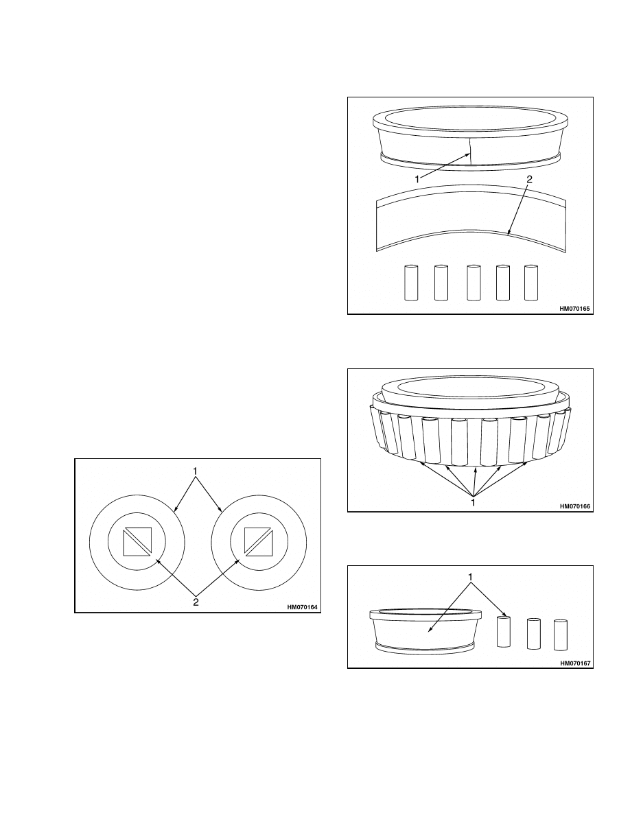
TAPERED ROLLER BEARINGS
Inspect cup, cone, rollers, and cage of all tapered
roller bearings in the assembly. If any of the follow-
ing conditions exist, replace bearing.
• The centers of the large diameter end of the rollers
are worn level with or below the surface. See Fig-
ure 10.
• The centers of the large diameter end of the rollers
are worn to a sharp edge. See Figure 10.
• A visible roller groove is worn in the cup or cone
inner race surfaces. You can see the groove at the
small or large diameter ends of both parts. See
Figure 11.
• Deep cracks or breaks are present in the cup, cone
inner race, or roller surfaces. See Figure 12.
• Bright wear marks are present on the outer surface
of the roller cage. See Figure 12.
• Etching and pitting is present on the rollers and on
surfaces of the cup and cone inner race that touches
the rollers. See Figure 13.
• Spalling or flaking is present on the cup and cone
inner race surfaces that touch the rollers. See Fig-
ure 14.
1.
WORN RADIUS
2.
WORN SURFACE
Figure 10. Tapered Roller Bearings
1.
CRACK
2.
WEAR GROOVES
Figure 11. Tapered Roller Bearings
1.
WEAR MARKS
Figure 12. Tapered Roller Bearings
1.
ETCHING AND PITTING
Figure 13. Tapered Roller Bearings
11
Parts Inspection
1400 SRM 945
1.
SPALLING AND FLAKING
Figure 14. Tapered Roller Bearings
BEVEL PINION AND RING GEAR SETS
CAUTION
The bevel drive pinions and ring gears are ma-
chined in matched sets. When a drive pinion
or ring gear of a bevel set needs to be replaced,
both drive gear and pinion must be replaced at
the same time. A higher stress on the original
parts and early failure of the entire assembly
will result if a new part is used in combination
with parts that are older or worn.
1.
Inspect bevel drive pinions and ring gears for
wear and damage. Gears that are worn or dam-
aged must be replaced.
2.
Verify condition of bearing cone seats and spline
on pinion shaft.
MAIN DIFFERENTIAL ASSEMBLY
1.
Use a cleaning solvent, kerosene, or diesel fuel
to clean interior of main differential assembly.
NEVER USE GASOLINE.
2.
Use left shaft to rotate one side gear. Replace
differential assembly if you see any binding.
3.
Observe side gear and differential pinions during
rotation. Replace differential assembly if you see
chipped or broken teeth, or if there are damaged
cases.
AXLE SHAFTS
If there is any wear or cracks at the flange, shaft, and
splines, replace axle shaft.
YOKE
If there is excessive wear at the seal journal area,
replace yoke.
BRAKES
See Dry Brake System 1800 SRM 937.
REPAIR OR REPLACE PARTS
Replace worn or damaged parts of an axle assembly.
The following are some examples to check for repair
and possible replacement.
• Replace any fastener if corners of head are worn.
• Replace washers if damaged.
• Replace gaskets, oil seals, or grease seals at time
of axle repair.
• Clean parts and apply new liquid gasket material
where required when axle is assembled.
• Remove nicks, marks, and burrs from parts having
machined or ground surfaces. Use a fine file, India
stone, emery cloth, or crocus cloth for this purpose.
• Clean and repair threads of fasteners and holes.
Use a die or tap of correct size or a fine file for this
purpose.
• If there is excessive wear at the seal journal area,
replace yoke.
Tighten all fasteners to correct
torque values. See Figure 20 and Figure 21 for
fastener torque value.
REPAIR WELDING
WARNING
Do not weld repair, heat, bend, or recondition
axle components. This will reduce component
strength and can result in serious personal in-
jury and damage to components. Always re-
place damaged or out-of-specification compo-
nents.
Inspect axle components.
Replace if damaged or
worn. Do not weld repair or recondition.
12
1400 SRM 945
Assembly
APPLY SILICONE GASKET MATERIAL
WARNING
When applying some silicone gasket materials,
small amounts of acid vapor are present. To
prevent possible serious injury, work area
must be well-ventilated. If the silicone gasket
material gets into your eyes, flush them with
water for 15 minutes. Have your eyes checked
by a doctor as soon as possible.
1.
Remove all old gasket material from surfaces of
both components.
2.
Clean surfaces where liquid gasket material will
be applied. Remove all oil, grease, dirt, and mois-
ture.
3.
Thoroughly dry both surfaces.
CAUTION
The amount of liquid gasket material applied
to component surface must not exceed 3.18 mm
(0.125 in.) diameter bead. Too much gasket ma-
terial can block lubrication passages. Damage
to components can result.
4.
Apply a 3.18 mm (0.125 in.) diameter continuous
bead of silicone gasket material around one sur-
face. Also apply gasket material around edge of
all fastener holes on that surface. See Figure 15.
5.
Assemble components immediately to permit
gasket material to compress evenly between
parts.
Tighten fasteners to required torque
value for that size fastener using an X torquing
pattern. See Figure 20 and Figure 21.
6.
Wait 20 minutes before filling assembly with lu-
bricant.
1.
SILICONE GASKET MATERIAL BEAD
Figure 15. Silicone Gasket
Assembly
SPINDLE, BRAKE SPIDER, AND BRAKE
WARNING
To prevent serious eye injury, always wear safe
eye protection when performing vehicle main-
tenance or service.
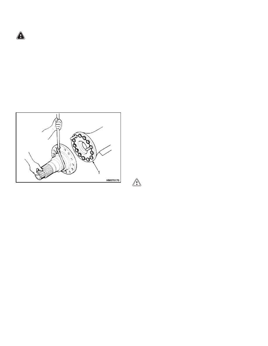
1.
Install two temporary studs (M16 - 2.0 threads,
approximately 101.6 mm (4 in.) long) into axle
housing flange. Install studs at eleven o’clock
and one o’clock positions. See Figure 16.
Figure 16. Spindle and Brake Spider Studs
13
Assembly
1400 SRM 945
WARNING
When you apply some silicone gasket materi-
als, small amounts of acid vapor are present. To
prevent possible serious injury, the work area
must be well ventilated. If the silicone gasket
material gets into your eyes, flush them with
water for 15 minutes. Have your eyes checked
by a doctor as soon as possible.
2.
Apply a 3.18 mm (0.125 in.) diameter continuous
bead of silicone gasket material around flange
mounting face of either axle housing or spindle.
Also apply gasket material around edge of all fas-
tener holes on that surface. See Figure 17.
1.
SILICONE GASKET MATERIAL BEAD
Figure 17. Spindle Assembly
3.
Install spindle onto axle housing.
4.
Install brake spider onto spindle.
5.
Install and hand tighten some spindle mounting
capscrews and washers.
6.
Remove two temporary studs.
7.
Install remaining spindle mounting capscrews
and washers. Tighten all capscrews to 270 to
350 N•m (200 to 260 lbf ft).
NOTE:
Replace camshaft bushing and grease seals
before camshaft bracket is installed onto brake spi-
der. See Dry Brake System 1800 SRM 937.
8.
Install brake camshaft bracket with O-ring on
pilot onto brake spider.
9.
Install four mounting capscrews and washers.
Tighten capscrews to 115 to 156 N•m (85 to
115 lbf ft).
10. Install brake camshaft bracket clamp around
bracket tube. Install two capscrews and wash-
ers that mount clamp to axle housing. Tighten
capscrews to 47 to 68 N•m (35 to 50 lbf ft).
11. Install air chamber-to-bracket mounting nuts.
Tighten nuts to 136 to 156 N•m (100 to 115 lbf ft).
12. Attach chamber push rod yoke to slack adjuster.
Tighten yoke jam nut to 34 to 68 N•m (25 to
50 lbf ft).
13. Install brake dust shield.
Tighten mounting
capscrews and washers to 47 to 68 N•m (35 to
50 lbf ft).
WHEEL END
1.
Press new inner and outer bearing cups into
wheel hub.
2.
Position wheel hub with oil seal bore facing UP.
3.
Apply axle gear lubricant to bearing rollers and
install inner wheel bearing cone.
CAUTION
• Do not damage hub oil seal bore surface in
wheel hub. Damage to this surface will result
in oil leakage after assembly.
• Apply a light film of nonhardening sealant
to hub bore surface to eliminate oil leakage
from outer diameter of seal.
• The hub oil seal is a "unitized" oil seal. The ro-
tating seal lips are internal. The rubber ribs
in the bore of the seal seat onto the spindle
journal surface for static sealing. The ribs
must not be cut or damaged to avoid an oil
leak path.
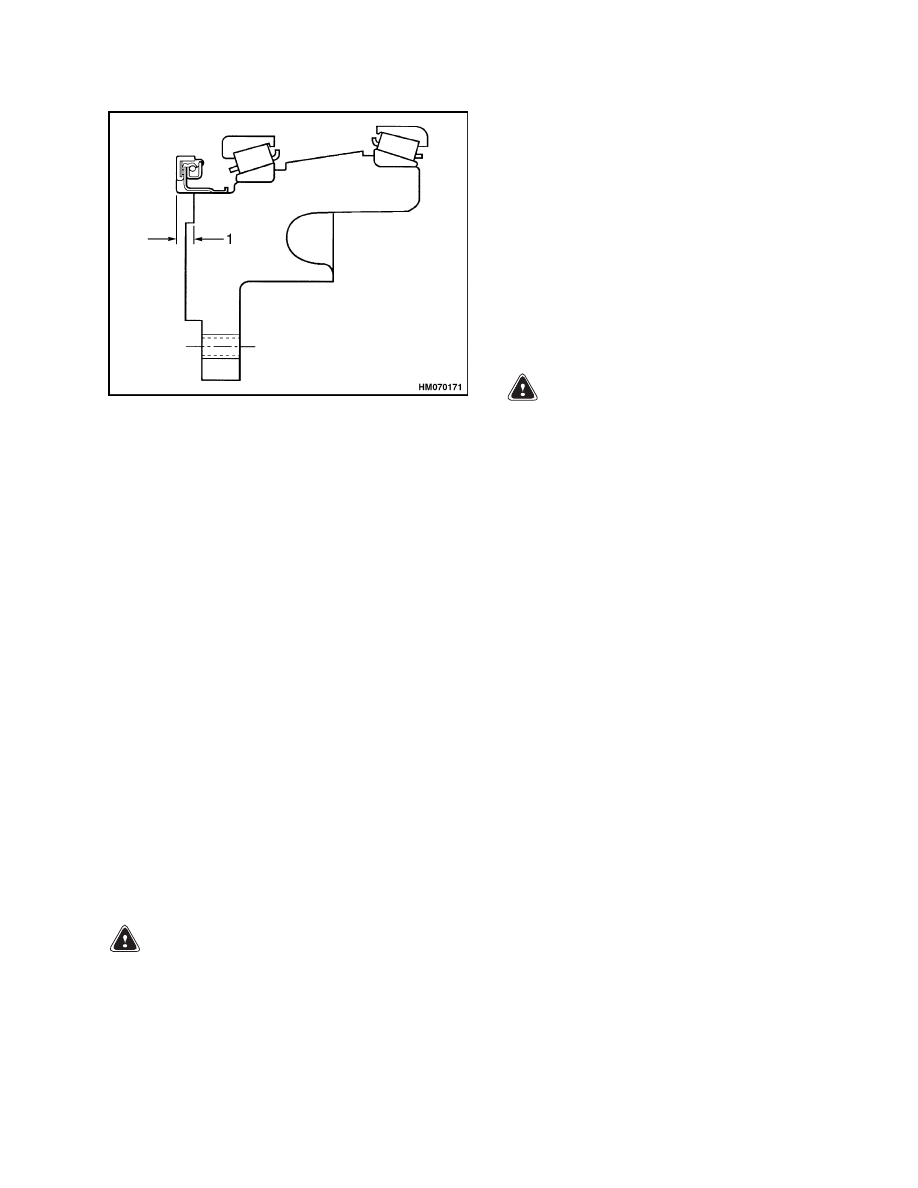
4.
Use correct oil seal driver to install wheel hub
oil seal. Press seal into hub until standout from
hub machined face is 8.64 mm (0.34 in.). See
Figure 18.
14
1400 SRM 945
Assembly
1.
8.64 mm (0.34 in.)
Figure 18. Wheel Hub Seal
NOTE:
Use a Permatex coating to seal against leaks
around hub oil seal. Leaks would result in requiring
disassembly, should leak be noted after final axle as-
sembly.
5.
Apply a light, uniform coating of Permatex to
wheel hub bore.
6.
Apply a light film of axle lubricant to hub oil seal
rubber ribs in oil seal bore.
7.
Install wheel hub, inner bearing, and oil seal as-
sembly onto spindle. Keep hub assembly aligned
with spindle.
8.
Apply axle lubricant to outer bearing cone
rollers. Install outer bearing cone onto plane-
tary ring gear hub.
9.
Install ring gear hub and bearing assembly onto
spindle.
ADJUST WHEEL BEARING PRELOAD
NOTE: To adjust wheel bearing preload, bearings
must be seated and rollers in proper alignment.
WARNING
Use a brass or leather mallet for assembly and
disassembly procedures. Do not hit steel parts
with a steel hammer. Pieces of a part can break
off and cause serious personal injury.
1.
Install wheel bearing adjusting nut. Tighten nut
to 542 N•m (400 lbf ft).
2.
Rotate hub in both directions. At the same time,
tap hub several times with a brass or plastic mal-
let.
3.
Tighten nut to 542 N•m (400 lbf ft) again.
4.
Back off nut approximately 1/4 turn to relieve
preload produced in Step 3.
5.
Tighten nut to 271 N•m (200 lbf ft).
NOTE: Step 6 and Step 7 vary between H8.00-
12.00XM
(H170-280HD)
and
H13.00-16.00XM
(H300-360HD) and H10.00XM-12EC (H360HD-EC).
Verify correct procedures.
WARNING
Carefully align adjusting nut dowel pin within
a ring gear tooth spline to avoid damage to pin.
A damaged dowel pin will cause adjusting nut
to back off and loosen wheel during vehicle op-
eration. This can result in serious personal in-
jury and damage to components.
6.
H8.00-12.00XM (H170-280HD).
Carefully align adjusting nut dowel pin within a
ring gear tooth spline to avoid damage to dowel
pin.
Tighten adjusting nut to produce proper
alignment. Do not back off adjusting nut.
H13.00-16.00XM (H300-360HD) and
H10.00XM-12EC (H360HD-EC).
Install lock plate.
7.
H8.00-12.00XM (H170-280HD).
Install planetary ring gear onto spindle.
The
dowel pin in adjusting nut must be installed in
hole in ring gear face to allow ring gear to seat
against adjusting nut.
H13.00-16.00XM (H300-360HD) and
H10.00XM-12EC (H360HD-EC).
Install lock plate mounting screws.
Tighten
mounting screws to 27 to 41 N•m (20 to 30 lbf ft).
8.
Apply a thin layer of axle grease to face of sun
gear thrust washer.
9.
Install sun gear thrust washer. Washer tangs
must engage holes in ring gear.
10. Install planetary sun gear and snap ring onto
axle shaft.
11. Install axle shaft and sun gear assembly. For
correct installation:
15
Assembly
1400 SRM 945
• Axle shaft must make contact with differential
side gear.
• Sun gear must make contact with thrust
washer.
• Thrust washer tangs must be properly in-
stalled in ring gear hub holes.
12. Install O-ring on wheel hub at base of flange.
PLANETARY SPIDER AND GEARING
ASSEMBLY H8.00-12.00XM (H170-280HD)
1.
If thrust button replacement is required, use the
procedure below. If thrust button is not to be
changed, proceed to Step 2.
WARNING
When applying some silicone gasket materials,
small amounts of acid vapor are present. To
prevent possible serious injury, work area
must be well ventilated. If the silicone gasket
material gets into your eyes, flush them with
water for 15 minutes. Have your eyes checked
by a doctor as soon as possible.
a. Apply liquid gasket material to axle shaft
thrust button shaft before pressing it into
spider.
b. Press new axle shaft thrust button into plan-
etary spider.
c.
Apply a film of nonhardening sealant to spi-
der pinion shaft bores.
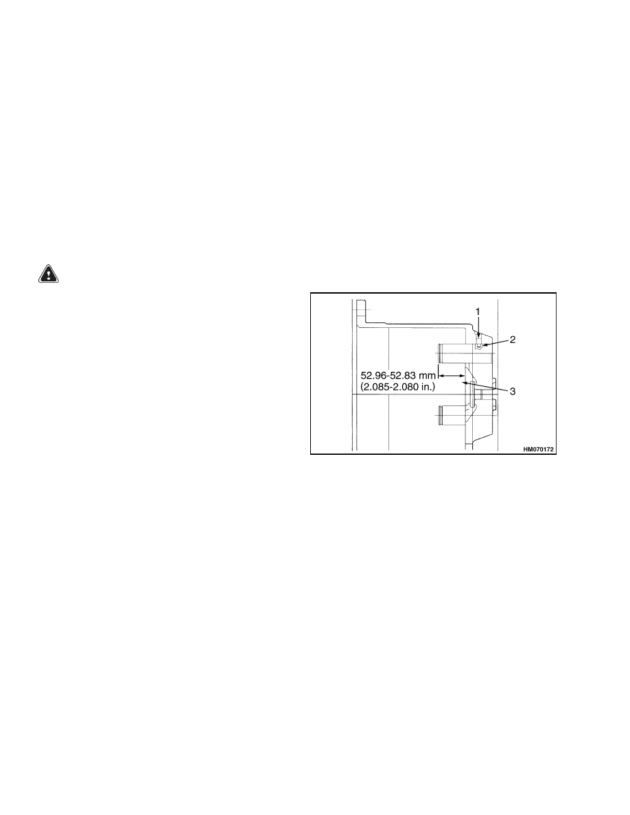
2.
Press pinion shafts into bores from inner cavity
end of spider. See Figure 19. Press noncoated
end of pinion shaft into spider until end of shaft
is 52.96 to 52.83 mm (2.085 to 2.080 in.) from
inside face of spider.
3.
Install a setscrew into each pinion shaft. Tighten
each setscrew to 47 N•m (35 lbf ft). For new
pinion shafts (if replaced), machine a hole for
setscrew in each shaft.
a. Drill an 8 mm (0.313 in.)
diameter hole
6.4 mm (0.25 in.) deep into pinion shaft.
b. Carefully pass drill through 0.375 inch-16
tapped hole in planetary spider boss.
c.
Install setscrew and tighten it to 47 N•m
(35 lbf ft).
4.
Apply gear lubricant to planetary pinion bores
and to pinion shaft journals.
5.
Install outer thrust washer with tang engaged
into slot in spider.
NOTE:
If original planetary pinions are used, verify
that gear bores are smooth and free of any surface
damage.
6.
Install planetary pinion, inner thrust washer,
and snap ring.
7.
Apply liquid gasket material on wheel hub
O-ring and adjacent area.
1.
ASSEMBLE THREE SETSCREWS AS SHOWN
2.
8 mm (0.313 in.) DIAMETER 0.25 IN. DEEP ONE
HOLE EACH SHAFT
3.
PRESS IN THREE SHAFTS TO DIMENSION
SHOWN
Figure 19. Pinion Shaft Assembly
PLANETARY SPIDER AND GEARING
ASSEMBLY H13.00-16.00XM (H300-360HD)
AND H10.00XM-12EC (H360HD-EC)
NOTE: If the original planetary pinions are used,
verify that gear bores are smooth and free of any sur-
face damage.
16

1400 SRM 945
Assembly
WARNING
When applying some silicone gasket materials,
small amounts of acid vapor are present. To
prevent possible serious injury, work area
must be well ventilated.
If silicone gasket
material gets into your eyes, flush them with
water for 15 minutes. Have your eyes checked
by a doctor as soon as possible.
1.
If axle shaft thrust button and/or ring gear thrust
buttons are being replaced, apply liquid gasket
material to them before pressing into spider.
2.
Place planetary spider on a workbench with
flange end facing UP. Press new buttons into
planetary spider.
3.
Inspect planet pinion bores for damage. Do not
reuse pinions with bore surface damage.
4.
Apply gear lubricant to planetary pinion bores
and to pinion shaft journals and shoulder sur-
faces.
5.
Place planetary spider on a workbench with
flange end facing DOWN.
6.
Carefully slide planetary spider over edge of
workbench just far enough to reach inside to
place a planetary pinion and thrust washer.
7.
Install planetary pinion and inner and outer
thrust washers from large end of planetary spi-
der. Thrust washer tangs of thrust washer must
engage slots in planetary spider inner and outer
support bosses.
8.
Replace O-ring on each pinion shaft and insert
pinion shafts.
Hand tighten them to support
journals. Large end of each pinion shaft must
face OUT.
9.
Press pinion shafts into spider until pinion shaft
inner shoulders contact thrust washers.
10. Apply a film of sealant to outside pinion shaft
bores of planetary spider.
11. Place planetary spider on a workbench with
flange end facing UP.
12. Install snap rings on each pinion shaft.
13. Install O-ring at base of wheel hub flange.
14. Installe planetary ring gear onto ring gear hub.
PLANETARY SPIDER ASSEMBLY
NOTE:
For correct installation, planetary pinions
must contact both sun gear and ring gear before
installation.
1.
Install planetary spider and gearing assembly
onto wheel hub.
2.
Install slotted head machine screws that tem-
porarily secure planetary spider to wheel hub.
Hand tighten screws. Seat head of each screw
below surface of spider flange.
3.
Install brake drum over wheel studs until drum
seats onto planetary spider flange.
4.
Mount inner and outer wheels.
Install wheel
nuts and tighten them to vehicle manufacturer’s
specification.
NOTE:
The E019, F007, F019, and G007 axles have
a common oil level between carrier and wheel ends.
Three locations must be filled. The vehicle must be
on a level surface when filling. Fill to bottom of each
fill plughole. Wait and allow oil to flow through axle.
Check oil level again after a few minutes and fill to
specified level if necessary.
5.
Add correct axle lubricant into each wheel end
through fill/level hole in planetary spider at hor-
izontal position (three or nine o’clock).
6.
Add correct lubricant to axle housing bowl area.
7.
Apply sealant to threads of fill/level plugs.
8.
Install fill/level plugs and tighten them to
47 N•m (35 lbf ft).
17

Installation
1400 SRM 945
Installation
NOTE:
During assembly and installation, see Fig-
ure 20 and Figure 21 for torque specifications. Lu-
bricate all parts with clean axle lubricant.
1.
If axle housing was removed, install it as de-
scribed in Step 2 through Step 6. Assemble plan-
etary assemblies as shown in Figure 6.
2.
Use a jack or forks of a lift truck to put axle under
frame. Install mount bolts and nuts as shown in
Figure 5. Tighten nuts to 920 N•m (680 lbf ft).
3.
Install brake components as described in the sec-
tion Dry Brake System 1800 SRM 937.
4.
Connect drive shaft to differential.
5.
Add air to tires. See the section Periodic Main-
tenance for your lift truck.
WARNING
Add air pressure to tires only in a safety cage.
Inspect safety cage for damage before use.
When air pressure is added to tire, use a chuck
that fastens onto valve stem of inner tube.
Make sure there is enough hose to permit op-
erator to stand away from safety cage when
air pressure is added to tire.
Do not sit or stand by safety cage. Do not use
a hammer to try and correct position of side
ring and/or lock ring when tire has air pressure
greater than 20 kPa (3 psi).
6.
Install wheels in reverse procedure as described
in Disassembly, Step 1 and Step 2. See Planetary
Spider Assembly, Step 4 for wheel installation
and axle lubrication.
18
1400 SRM 945
Torque Specifications
Torque Specifications
Item
Fastener
Torque Value
1
Wheel rim nut
Per OEM specifications
2
Pinion shaft setscrew
47 N•m (35 lbf ft)
3
Oil fill/level/drain plug
47 N•m (35 lbf ft)
4
Planetary spider to wheel hub slotted head
screw
Hand tighten (no specification)
5
Spindle and brake spider mounting (drum)
270 to 350 N•m (200 to 260 lbf ft)
6
Camshaft bracket clamp
47 to 68 N•m (35 to 50 lbf ft)
7
Camshaft bracket to spider
115 to 156 N•m (85 to 115 lbf ft)
8
Wheel bearing adjusting nut
Refer to Adjust Wheel Bearing Preload.
Figure 20. Wheel End Torque Chart H8.00-12.00XM (H170-280HD)
19
Lubrication Specification
1400 SRM 945
Item
Fastener
Torque Value
1
Wheel rim nut
Per OEM specification
2
Lock plate screw
27 to 41 N•m (20 to 30 lbf ft)
3
Wheel bearing adjusting nut
Refer to Adjust Wheel Bearing Preload.
4
Planetary spider to wheel slotted head screw
Hand tighten (no specification)
5
Camshaft bracket to spider
115 to 156 N•m (85 to 115 lbf ft)
6
Camshaft bracket clamp
47 to 68 N•m (35 to 50 lbf ft)
7
Spindle and brake mounting
500 to 650 N•m (370 to 480 lbf ft)
8
Oil fill/drain plug
47 N•m (35 lbf ft)
Figure 21. Wheel End Torque Chart H13.00-16.00XM (H300-360HD) and H10.00XM-12EC
(H360HD-EC)
Lubrication Specification
See Periodic Maintenance for your lift truck.
20


TECHNICAL PUBLICATIONS
1400 SRM 945
9/03 (2/01) Printed in U.S.A.
Document Outline
- toc
Wyszukiwarka
Podobne podstrony:
1494953 1400SRM0944 (09 2003) UK EN
1510463 1400SRM0984 (09 2003) UK EN
897391 1400SRM0450 (09 2003) UK EN
910073 1400SRM0049 (09 2003) UK EN
1466247 1400SRM0731 (09 2003) UK EN
897394 1900SRM0453 (09 2003) UK EN
897987 1800SRM0659 (09 2003) UK EN
1494955 2000SRM0943 (09 2003) UK EN
897110 1900SRM0328 (09 2003) UK EN
897993 1600SRM0671 (09 2003) UK EN
897392 1600SRM0451 (09 2003) UK EN
1466235 1600SRM0733 (09 2003) UK EN
1466223 1900SRM0753 (09 2003) UK EN
więcej podobnych podstron