HYDRAULIC SYSTEM
S6.00-7.00XL (S135-155XL, S155XLS,
S135-155XL
2
) [B024, C024]
PART NO. 897394
1900 SRM 453

SAFETY PRECAUTIONS
MAINTENANCE AND REPAIR
• When lifting parts or assemblies, make sure all slings, chains, or cables are correctly
fastened, and that the load being lifted is balanced. Make sure the crane, cables, and
chains have the capacity to support the weight of the load.
• Do not lift heavy parts by hand, use a lifting mechanism.
• Wear safety glasses.
• DISCONNECT THE BATTERY CONNECTOR before doing any maintenance or repair
on electric lift trucks.
• Disconnect the battery ground cable on internal combustion lift trucks.
• Always use correct blocks to prevent the unit from rolling or falling. See HOW TO PUT
THE LIFT TRUCK ON BLOCKS in the Operating Manual or the Periodic Mainte-
nance section.
• Keep the unit clean and the working area clean and orderly.
• Use the correct tools for the job.
• Keep the tools clean and in good condition.
• Always use HYSTER APPROVED parts when making repairs. Replacement parts
must meet or exceed the specifications of the original equipment manufacturer.
• Make sure all nuts, bolts, snap rings, and other fastening devices are removed before
using force to remove parts.
• Always fasten a DO NOT OPERATE tag to the controls of the unit when making repairs,
or if the unit needs repairs.
• Be sure to follow the WARNING and CAUTION notes in the instructions.
• Gasoline, Liquid Petroleum Gas (LPG), Compressed Natural Gas (CNG), and Diesel fuel
are flammable. Be sure to follow the necessary safety precautions when handling these
fuels and when working on these fuel systems.
• Batteries generate flammable gas when they are being charged. Keep fire and sparks
away from the area. Make sure the area is well ventilated.
NOTE:
The following symbols and words indicate safety information in this
manual:
WARNING
Indicates a condition that can cause immediate death or injury!
CAUTION
Indicates a condition that can cause property damage!
Hydraulic System
Table of Contents
TABLE OF CONTENTS
General ...............................................................................................................................................................
Description and Operation ................................................................................................................................
Main Hydraulic Pump ...................................................................................................................................
Steering Pump ...............................................................................................................................................
Main Control Valve........................................................................................................................................
Control Valve Lever .......................................................................................................................................
Filter...............................................................................................................................................................
Steering Control Unit ....................................................................................................................................
Brake Booster ................................................................................................................................................
Main Hydraulic Pump Repair ...........................................................................................................................
Remove ...........................................................................................................................................................
Disassemble ...................................................................................................................................................
Clean and Inspect ..........................................................................................................................................
Assemble ........................................................................................................................................................
Install .............................................................................................................................................................
Specifications......................................................................................................................................................
Hydraulic System ..........................................................................................................................................
Hydraulic Tank ..............................................................................................................................................
Hydraulic Oil .................................................................................................................................................
Relief Pressures* ...........................................................................................................................................
Hydraulic Pump.............................................................................................................................................
Steering Pump ...............................................................................................................................................
Troubleshooting..................................................................................................................................................
This section is for the following models:
S6.00-7.00XL (S135-155XL, S155XLS, S135-155XL
2
) [B024, C024]
©2003 HYSTER COMPANY
i

"THE
QUALITY
KEEPERS"
HYSTER
APPROVED
PARTS

1900 SRM 453
Description and Operation
General
This section has the description and operation of the
complete hydraulic system and brief descriptions of
the components of the hydraulic system. There is
the main hydraulic system for the lifting, lowering,
and tilting circuits. There is the steering and brake
booster hydraulic circuit. There are also hydraulic
circuits in the oil clutch and powershift transmis-
sion.
This section covers the main and steering
hydraulic systems.
The repair procedures for the
main hydraulic pump and a troubleshooting guide
for these hydraulic systems is also included. See the
section Oil Clutch System 1200 SRM 334 for the
description and operation of the hydraulic system of
the oil clutch. See the section Two-Speed Power-
shift Transmission-Description and Operation
1300 SRM 324 for the description and operation of
the powershift transmission.
Description and Operation
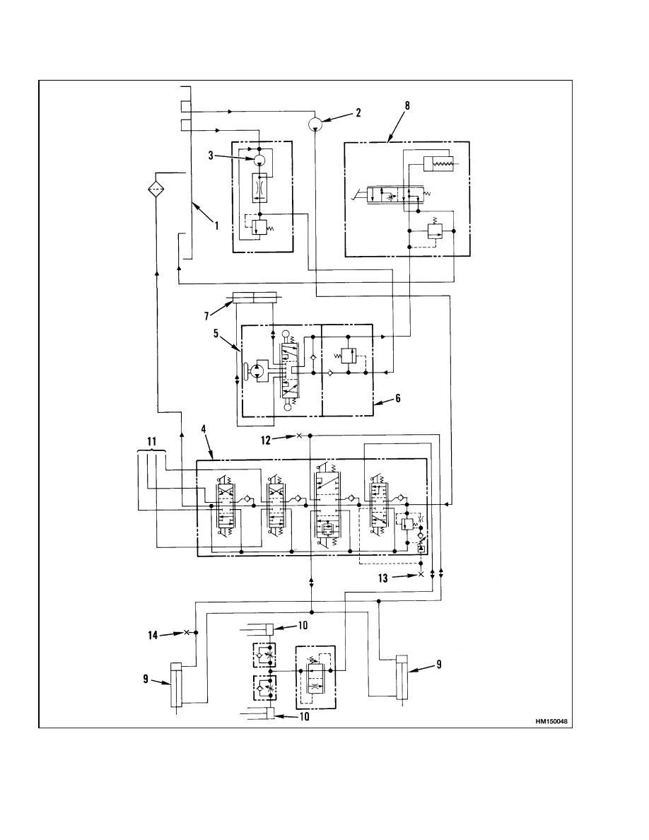
The hydraulic system includes the circuits for the up-
right, steering system, and the brake system. See
Figure 1. There is a separate hydraulic pump (steer-
ing pump) for the steering system and brake booster.
The main hydraulic pump is driven by a chain from
the engine flywheel. The steering pump is driven by
the fan belts on units with the GM engine. On units
with the Perkins diesel engine, the steering pump
is driven by the timing gears. The main hydraulic
pump and the steering pump get their oil supply from
the hydraulic tank.
MAIN HYDRAULIC PUMP
The main hydraulic pump is a gear pump. This pump
supplies oil to the main control valve to operate the
lift, tilt and auxiliary functions. Oil from the main
control valve returns to the hydraulic tank through
a filter. See Figure 2.
STEERING PUMP
The steering pump is a vane pump. This pump sup-
plies oil to the steering system. Return oil from the
steering system goes to the brake booster. Oil from
the brake booster returns to the hydraulic tank.
MAIN CONTROL VALVE
The main control valve controls the lift, lower, tilt
and attachment functions. See Figure 3. The control
valve receives oil from the hydraulic pump. The main
relief valve (lift circuit) is set at 21.03 MPa (3050 psi).
The auxiliary relief valve for the tilt and attachment
circuits is set at 15.5 MPa (2250 psi). The drain cir-
cuit from the main control valve is connected to the
hydraulic filter. Oil from the filter returns to the hy-
draulic tank. See Figure 4.
Oil flow in the main control valve goes first to the
main relief valve and the lift/lower spool. If none
of the spools are actuated, the oil flows by all of the
spools and returns to the hydraulic tank. When the
lift/lower spool is moved to LIFT position by the lift/
lower lever, the oil flows to the lift cylinders.
At
this time the main relief valve controls the maxi-
mum pressure in the hydraulic system. If the tilt
or lift/lower spool is actuated, oil cannot flow to the
auxiliary spools. When the tilt or auxiliary spools
are actuated, the secondary relief valve controls the
maximum pressure in the hydraulic system.
The auxiliary spools are actuated by the auxiliary
hand lever. Push the lever to the right and forward
to open the clamp. Push the lever to the right and
pull back to close the clamp.
These lift trucks can have a solenoid operated valve
to control a fifth auxiliary hydraulic function. This
valve is installed on the right side of the cowl. The oil
supply for the solenoid valve and attachment comes
from the main control valve. The solenoid valve is
controlled by a switch on the knob of the control
lever for the auxiliary functions. The button allows
the lever to control three functions of an attachment.
The button operates only when the lever is in the
left position (see the Operating Manual):
Button not depressed: Push the lever forward to
rotate the attachment to the left. Pull back on the
lever to rotate the attachment to the right.
Button depressed: Push the lever forward to swing
the attachment to the left. Pull back on the lever to
swing the attachment to the right.
1
Description and Operation
1900 SRM 453
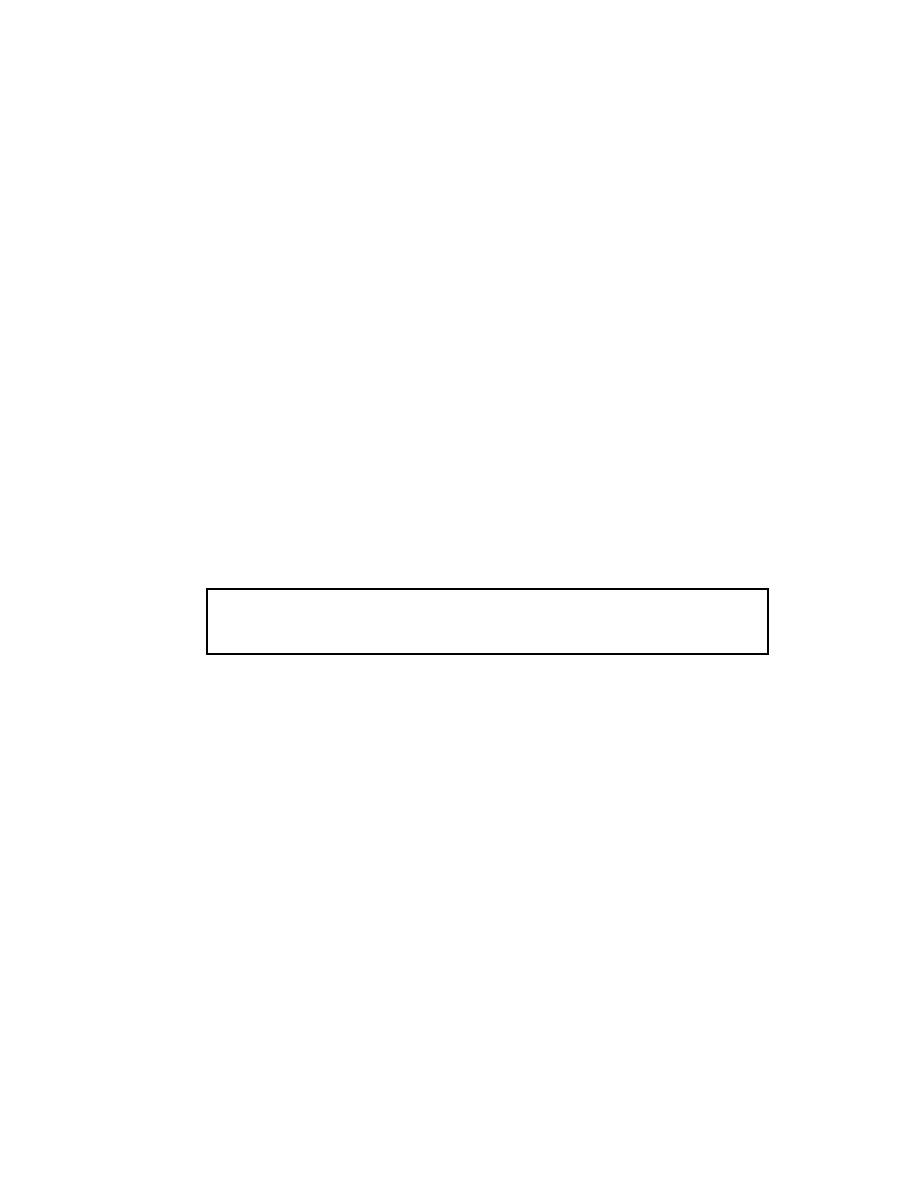
1.
HYDRAULIC TANK
2.
MAIN HYDRAULIC PUMP
3.
HYDRAULIC FILTER
4.
MAIN CONTROL VALVE
5.
MANIFOLD BLOCK FOR STEERING CONTROL
UNIT
6.
BRAKE BOOSTER
7.
STEERING CYLINDER
8.
LIFT CYLINDER
9.
TILT CYLINDER
10. TANK BREATHER
11. TEST PORT, TILT CIRCUIT (EARLY MODELS)
(B024)
12. RELIEF VALVE
13. STEERING PUMP
14. TEST PORT, LIFT CIRCUIT
15. TEST PORT, TILT CIRCUIT (LATE MODELS)
(B024, C024)
Figure 1. Hydraulic System Diagram
2
1900 SRM 453
Description and Operation
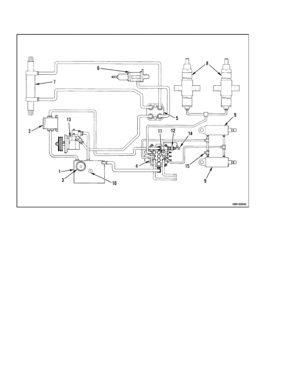
1.
INLET FROM HYDRAULIC TANK
2.
OUTLET TO MAIN CONTROL VALVE
3.
END HOUSING
Figure 2. Hydraulic Pump
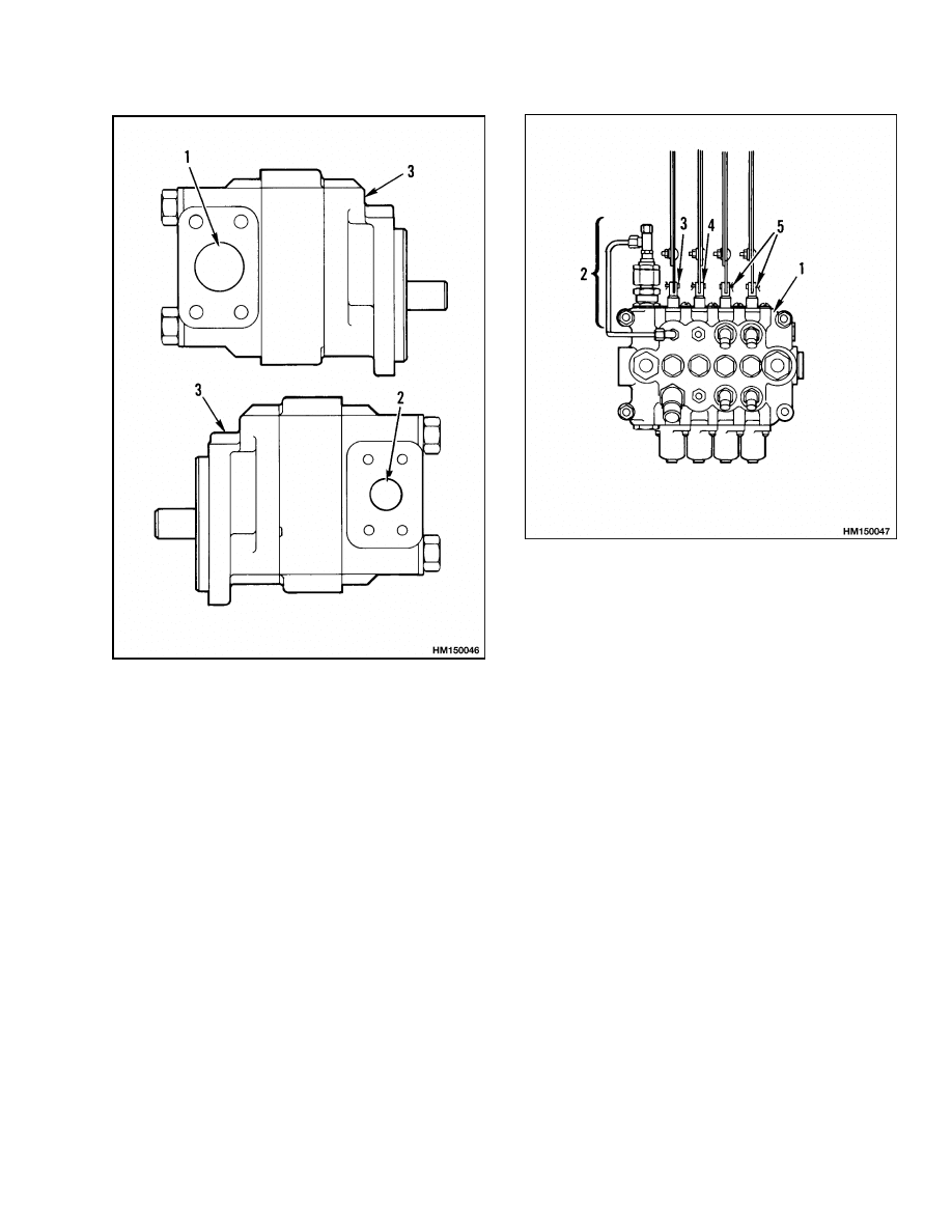
1.
MAIN CONTROL VALVE
2.
RELIEF VALVE
3.
LIFT/LOWER SPOOL
4.
TILT SPOOL
5.
AUXILIARY SPOOL
Figure 3. Main Control Valve
3
Description and Operation
1900 SRM 453
Figure 4. Hydraulic System Schematic
4
1900 SRM 453
Description and Operation
Legend for Figure 4
1.
HYDRAULIC TANK
2.
MAIN HYDRAULIC PUMP
3.
STEERING PUMP
4.
MAIN CONTROL VALVE
5.
STEERING CONTROL VALVE
6.
MANIFOLD BLOCK
7.
STEERING CYLINDER
8.
BRAKE BOOSTER
9.
TILT CYLINDER
10. LIFT CYLINDER
11. AUXILIARY FUNCTIONS
12. TEST PORT, TILT CIRCUIT (EARLY MODELS)
(B024)
13. TEST PORT, LIFT CIRCUIT
14. TEST PORT, TILT CYLINDER (LATE MODELS)
(B024, C024)
CONTROL VALVE LEVER
If the lever weldment bypasses the control valve
lever locks, use the following procedure:
Check to see if the selector pin has an overall width
of 23.8 mm (0.9 in.). If the pin width is greater than
23.8 mm (0.9 in.), grind the pin to the proper dimen-
sion.
Verify that there are two shims between the 2nd and
3rd function lever that measure 0.254 mm (0.010 in.)
and 0.508 mm (0.20 in.).
FILTER
The filter has a replaceable 25 micron element and is
located in the hydraulic tank. The filter has a bypass
valve so that oil can flow around the filter when the
filter becomes restricted. Oil from the filter returns
to the hydraulic tank.
STEERING CONTROL UNIT
The steering control unit is a rotary valve that con-
trols the flow of oil at the three outlet ports. Two
of these ports control the movement of the steering
cylinder. When the steering wheel is rotated, oil flow
is directed to the steering cylinder. The amount and
direction of the oil flow is controlled by the direc-
tion and rate of the steering wheel rotation. The
control unit has a minimum restriction to oil flow
when the steering wheel is not moved. The control
unit has four ports; inlet, the two control ports and
the drain port. Oil from the drain port goes to the
brake booster. See the section Steering Control
Unit 1600 SRM 54 for more information and repair
procedures.
A manifold block is installed on the steering control
unit over the four ports. The inlet port in the man-
ifold block has a check valve and a relief valve and
is connected to the steering pump. The relief valve is
set at 12.07 MPa (1750 psi). Two of the ports are con-
nected to the steering cylinder. The port for the drain
circuit is connected to the inlet of the brake booster.
All of the oil that flows to the steering control unit
also flows to the brake booster. The steering control
unit can operate the steering cylinder to manually
steer the unit if the engine is not operating. This ac-
tion takes more effort by the operator.
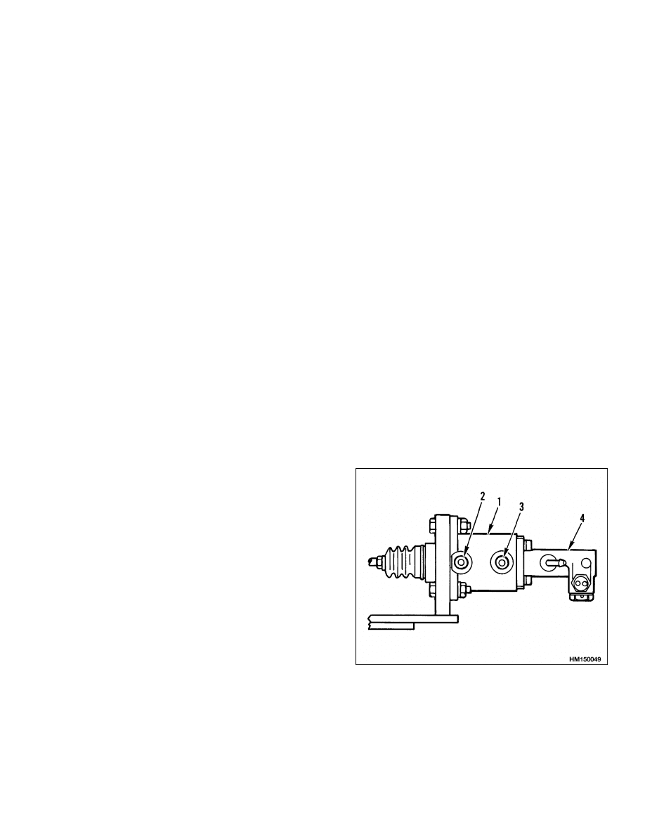
BRAKE BOOSTER
The brake system on these lift trucks uses a hy-
draulic actuator (brake booster) to actuate the
master cylinder. See Figure 5. The operation of the
brake booster decreases the foot pressure necessary
to apply the brakes. The oil flow from the outlet
of the steering control unit is used to operate the
brake booster. A relief valve in the brake booster is
set at 2275 kPa (330 psi). The brake will operate
with more effort by the operator if the engine is not
operating.
1.
BRAKE BOOSTER
2.
INLET
3.
OUTLET
4.
MASTER
CYLINDER
Figure 5. Brake Booster
5
Main Hydraulic Pump Repair
1900 SRM 453
Main Hydraulic Pump Repair
REMOVE
NOTE: Worn or damaged seals are the most common
cause of hydraulic pump repair. The pump bearings,
gears or vanes, and shafts also wear. Most service
persons do not repair a worn pump because the cost
of repairs can be greater than the cost of a new pump.
The seals can be replaced in a hydraulic pump. Re-
place a worn or damaged hydraulic pump.
1.
Put the lift truck on blocks as described in the
Operating Manual or the Periodic Main-
tenance 8000 SRM 393. The main hydraulic
pump must be removed from the bottom of the
lift truck.
2.
Disconnect the battery and remove the battery
and battery tray.
3.
Remove the breather from the hydraulic tank.
Put a plug in the tank fitting and dipstick tube
so that the tank has an air lock. Disconnect the
return line at the tank and put a cap on the fit-
ting.
4.
Remove the hose between the hydraulic pump
and the tank. Put a plug in the suction tube (to
pump) on the hydraulic tank.
5.
Disconnect the supply hose to the steering con-
trol unit at the steering pump. Put a plug in the
hose.
6.
Remove the capscrews for the pump and remove
the pump from the flywheel housing.
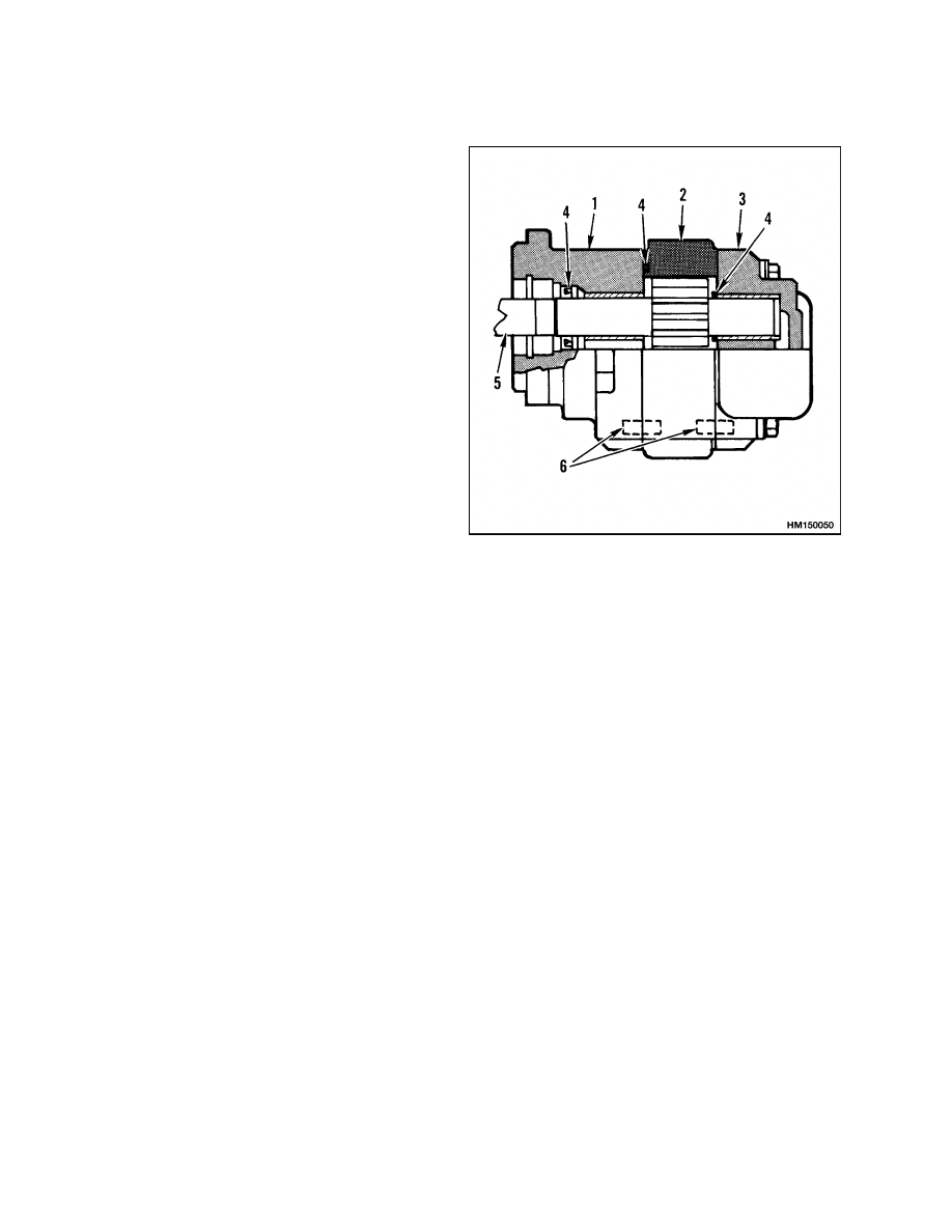
DISASSEMBLE
NOTE:
If the pump is held in a vise for disassembly,
make sure the vise does not hold the pump too tightly
and cause damage to the pump body.
Make sure to take careful notes of the location of
the parts and seals during disassembly. Some of the
parts are similar but are not exactly the same. Use a
punch to make alignment marks on the parts of the
housing. See Figure 2 and Figure 6.
1.
SHAFT HOUSING
2.
GEAR HOUSING
3.
END HOUSING
4.
SEAL
5.
DRIVE SHAFT
6.
ALIGNMENT PIN
Figure 6. Hydraulic Pump
1.
Remove the four capscrews that hold the pump
together. Carefully separate the housing pieces.
2.
Remove the gears and thrust plates from the
housing.
3.
Remove the snap ring that holds the seal retainer
in the shaft housing. Remove the seal retainer
and seals for the drive shaft. Make a note of the
arrangement of the seals.
CLEAN AND INSPECT
Inspect the gear assembly and the housing parts for
wear and damage. Replace a damaged or worn hy-
draulic pump. If just the gears are replaced, they
must be replaced as a set.
NOTE: Some pump bodies will show gear marks
where the gears rotate because of the small clear-
ances between the parts. These gear marks do not
indicate a worn or damaged pump unless the pump
will not supply the volume and pressure shown in
the specifications.
6

1900 SRM 453
Specifications
ASSEMBLE
1.
Make sure the internal parts of the pump are
clean. Lubricate the parts with hydraulic oil as
they are installed into the pump. See Figure 2
and Figure 6.
2.
Install the seals in the shaft housing. Install the
seal in the seal retainer. Install the O-ring on the
seal retainer, then install the seal retainer and
snap ring.
3.
Make sure the four alignment pins are in the
housings. Install the gears, thrust plates, and
gear housing to the shaft housing. Make sure
the O-rings are installed between the housings
and between the thrust plates and the housings.
4.
Install the O-ring between the gear housing and
the end housing. Install the end housing and the
capscrews.
INSTALL
Install the hydraulic pump on the flywheel housing.
Use a sealant (Hyster Part Number 264159) on the
flange of the pump. Connect the oil lines to the main
pump, hydraulic tank, steering pump, and the main
control valve. Remove the plug and install the hy-
draulic tank breather.
Specifications
HYDRAULIC SYSTEM
Capacity
50.2 liter (13.3 gal)
HYDRAULIC TANK
Capacity
39.5 liter (10.4 gal) Drain & Refill
HYDRAULIC OIL
See the Periodic Maintenance 8000 SRM 393.
RELIEF PRESSURES*
Main Control Valve
Lift Circuit 21.03 MPa (3050 psi)
Tilt and Auxiliary Circuit 15.51 MPa (2250 psi)
Steering Circuit
12.075 MPa (1750 psi)
Brake Booster
2.275 MPa (330 psi)
HYDRAULIC PUMP
Capacity 102 liter/min (27.0 gal/min) at
21.0 MPa (3050 psi)
STEERING PUMP
Capacity 19.7 liter/min (5.2 gal/min) at
12.075 MPa (1750 psi)
*Oil temperature 50 to 100 C (120 to 210 F) and engine speed at 2500 rpm.
7

Troubleshooting
1900 SRM 453
Troubleshooting
PROBLEM
POSSIBLE CAUSE
PROCEDURE OR ACTION
The pump makes more noise
than normal.
The oil level is not correct or there is
no oil in the tank (cavitation).
Check oil level and fill as required.
Check for leaks.
Wrong type or grade of hydraulic
oil for the temperature or operation
(cavitation).
Check, drain tank, and fill with cor-
rect specified oil.
The suction screen has a restriction
(cavitation).
Clean or install new screen.
The inlet fitting is loose or hoses are
allowing air to enter the system (aer-
ation).
Tighten fitting.
Install new hoses.
Remove air from system.
The pump bearings or gears have
damage.
Repair or install new pump.
The capscrews that hold the pump
together are loose.
Tighten
capscrews
to
specified
torque.
The pump is loose.
Tighten fasteners to specified torque.
The pump drive mechanism is loose,
worn, or has damage.
Check, repair, or install new parts as
required.
The output of the pump is
less than specifications.
See, the pump makes more noise
than normal, Possible Cause section
above.
See, the pump makes more noise than
normal, Procedure or Action section
above.
The pump has leaks.
The fittings or hoses on the outlet
side of the pump are loose or dam-
aged.
Tighten fittings. Install new parts as
necessary.
The capscrews that hold the pump
together are loose.
Tighten
capscrews
to
specified
torque.
The seals in the pump are damaged.
Install new seals or new pump.
The pressure for the steer-
ing system is below specifi-
cations.
The relief valve is not adjusted cor-
rectly.
Adjust or install new relief valve.
The relief valve has damage.
Repair or install new relief valve.
The pump is worn.
Repair or install new pump.
8

1900 SRM 453
Troubleshooting
PROBLEM
POSSIBLE CAUSE
PROCEDURE OR ACTION
The flow for the steering sys-
tem is below specifications.
The flow control valve is not operat-
ing correctly.
Repair or install new flow control
valve.
The relief valve is not adjusted cor-
rectly.
Adjust or install new relief valve.
Hydraulic functions will not
operate.
There is no oil or not enough oil in
the hydraulic tank.
Repair any hydraulic leaks. Add hy-
draulic oil.
The hydraulic pump is damaged.
Repair hydraulic pump.
The hydraulic pump chain drive is
damaged.
Repair chain drive.
Hydraulic pressure is above
or below specifications.
Relief valve in main control valve is
not adjusted correctly.
Replace or adjust relief valve.
There is a restriction in the hy-
draulic line(s).
Remove restriction.
The hydraulic pump is worn or dam-
aged.
Repair or replace hydraulic pump.
LIFT, LOWER, AND TILT CIRCUIT
Slow or no movement of
cylinder(s).
Relief valve in main control valve is
damaged or is not adjusted correctly.
Replace or adjust relief valve.
Large leaks between the spool and
bore in the main control valve.
Repair or replace control valve sec-
tion.
Control valve spool not fully ex-
tended or retracted.
Check adjustment of control linkage.
Broken spring(s) for the spool(s).
Repair control valve.
The hydraulic pump is damaged.
Replace hydraulic pump.
The hydraulic pump chain is dam-
aged.
Repair chain drive.
Air is in the hydraulic system. There
is a restriction in the hydraulic
line(s).
Operate hydraulic system to remove
air. Check for leaks on inlet to hy-
draulic pump. Remove any restric-
tion.
9

Troubleshooting
1900 SRM 453
PROBLEM
POSSIBLE CAUSE
PROCEDURE OR ACTION
Slow or no movement of
cylinder(s). (Cont.)
The load is greater than the capacity
of the system.
Reduce load.
The cylinder seals are damaged.
Replace seals.
Lift cylinders retract when
the spool is in the Neutral
position.
Oil leaks between the spool and the
bore.
Repair or replace control valve sec-
tion.
Cylinder seals or the check valves
leak.
Check and repair leaks.
Hydraulic line(s) to the cylinder
leaks.
Repair hydraulic lines.
Tilt cylinder rods move for-
ward when the spool is in the
Neutral position.
Tilt control spool inside the tilt spool
does not work correctly.
Clean and repair or replace tilt spool
section.
Oil leaks between the spool and the
bore.
Clean and repair or replace tilt spool
section.
Hydraulic line(s) leak.
Repair hydraulic lines.
Tilt cylinder seals have leaks.
Check and repair leaks.
Lift cylinder rods move down
when the lift spool is moved
to the Lift position.
The load check valve is damaged.
Clean and repair or replace lift/lower
section of main control valve.
STEERING AND BRAKE SYSTEM
There is no action when the
steering wheel is turned.
There is no oil or not enough oil in
the hydraulic tank.
Check and repair leaks.
Add hy-
draulic oil.
Hydraulic lines to the steering cylin-
der are damaged or have a restric-
tion.
Repair hydraulic lines.
The steering pump does not operate
correctly.
Replace steering pump.
The steering control unit is dam-
aged.
Repair steering control unit.
10

1900 SRM 453
Troubleshooting
PROBLEM
POSSIBLE CAUSE
PROCEDURE OR ACTION
There is no action when the
steering wheel is turned.
(Cont.)
There is air in the hydraulic system.
Operate hydraulic system to remove
air. Check for leaks on inlet to hy-
draulic pump. Remove any restric-
tion.
The lift truck steers slowly,
or the steering wheel is hard
to turn.
Hydraulic lines to the steering cylin-
der are damaged or have a restric-
tion.
Repair hydraulic lines.
The steering pump does not operate
correctly.
Replace steering pump.
The steering pump is worn or dam-
aged.
Replace steering pump.
The steering wheel turns in
the wrong direction.
Hydraulic lines to the steering con-
trol unit or steering cylinder are not
connected correctly.
Check connections of hydraulic lines.
The brake booster does not
operate correctly.
The hydraulic line from the steering
control unit has a restriction or a
leak.
Repair hydraulic leak.
The hydraulic line from the brake
booster to the hydraulic tank has a
restriction.
Remove any restriction or repair hy-
draulic line.
11

NOTES
____________________________________________________________
____________________________________________________________
____________________________________________________________
____________________________________________________________
____________________________________________________________
____________________________________________________________
____________________________________________________________
____________________________________________________________
____________________________________________________________
____________________________________________________________
____________________________________________________________
____________________________________________________________
____________________________________________________________
____________________________________________________________
____________________________________________________________
____________________________________________________________
____________________________________________________________
____________________________________________________________
____________________________________________________________
____________________________________________________________
12


TECHNICAL PUBLICATIONS
1900 SRM 453
9/03 (3/89) Printed in United Kingdom
Document Outline
- toc
Wyszukiwarka
Podobne podstrony:
897110 1900SRM0328 (09 2003) UK EN
1466223 1900SRM0753 (09 2003) UK EN
1494953 1400SRM0944 (09 2003) UK EN
1498445 1400SRM0945 (09 2003) UK EN
910092 1900SRM0098 (07 2003) UK EN
1510463 1400SRM0984 (09 2003) UK EN
897987 1800SRM0659 (09 2003) UK EN
1494955 2000SRM0943 (09 2003) UK EN
897121 1900SRM0339 (10 2003) UK EN
897993 1600SRM0671 (09 2003) UK EN
897391 1400SRM0450 (09 2003) UK EN
897392 1600SRM0451 (09 2003) UK EN
1466235 1600SRM0733 (09 2003) UK EN
910073 1400SRM0049 (09 2003) UK EN
1466247 1400SRM0731 (09 2003) UK EN
897113 8000SRM0331 (09 2003) UK EN
więcej podobnych podstron