MAIN CONTROL VALVE
H8.00-12.00XM (H170-280HD) [F007, G007];
H13.00-16.00XM (H330-360HD) [E019, F019];
H10.00-12.00XM-12EC (H360HD-EC) [E019, F019]
PART NO. 1494955
2000 SRM 943

SAFETY PRECAUTIONS
MAINTENANCE AND REPAIR
• When lifting parts or assemblies, make sure all slings, chains, or cables are correctly
fastened, and that the load being lifted is balanced. Make sure the crane, cables, and
chains have the capacity to support the weight of the load.
• Do not lift heavy parts by hand, use a lifting mechanism.
• Wear safety glasses.
• DISCONNECT THE BATTERY CONNECTOR before doing any maintenance or repair
on electric lift trucks.
• Disconnect the battery ground cable on internal combustion lift trucks.
• Always use correct blocks to prevent the unit from rolling or falling. See HOW TO PUT
THE LIFT TRUCK ON BLOCKS in the Operating Manual or the Periodic Mainte-
nance section.
• Keep the unit clean and the working area clean and orderly.
• Use the correct tools for the job.
• Keep the tools clean and in good condition.
• Always use HYSTER APPROVED parts when making repairs. Replacement parts
must meet or exceed the specifications of the original equipment manufacturer.
• Make sure all nuts, bolts, snap rings, and other fastening devices are removed before
using force to remove parts.
• Always fasten a DO NOT OPERATE tag to the controls of the unit when making repairs,
or if the unit needs repairs.
• Be sure to follow the WARNING and CAUTION notes in the instructions.
• Gasoline, Liquid Petroleum Gas (LPG), Compressed Natural Gas (CNG), and Diesel fuel
are flammable. Be sure to follow the necessary safety precautions when handling these
fuels and when working on these fuel systems.
• Batteries generate flammable gas when they are being charged. Keep fire and sparks
away from the area. Make sure the area is well ventilated.
NOTE:
The following symbols and words indicate safety information in this
manual:
WARNING
Indicates a condition that can cause immediate death or injury!
CAUTION
Indicates a condition that can cause property damage!
Main Control Valve
Table of Contents
TABLE OF CONTENTS
General ...............................................................................................................................................................
Description .........................................................................................................................................................
Operation............................................................................................................................................................
Lift Section .....................................................................................................................................................
Tilt/Auxiliary Section ....................................................................................................................................
Relief Valves...................................................................................................................................................
Unloader Valve...............................................................................................................................................
Main Control Valve Repair ................................................................................................................................
Remove ...........................................................................................................................................................
Disassemble ...................................................................................................................................................
Auxiliary Side ............................................................................................................................................
Lift Side .....................................................................................................................................................
Clean and Inspect ..........................................................................................................................................
Assemble ........................................................................................................................................................
Auxiliary Side ............................................................................................................................................
Lift Side .....................................................................................................................................................
Install .............................................................................................................................................................
Pressure Relief Valve Check and Adjustment..................................................................................................
Check and Adjust...........................................................................................................................................
Replace ...........................................................................................................................................................
Specifications......................................................................................................................................................
Troubleshooting..................................................................................................................................................
This section is for the following models:
H8.00-12.00XM (H170-280HD) [F007, G007];
H13.00-16.00XM (H330-360HD) [E019, F019];
H10.00-12.00XM-12EC (H360HD-EC) [E019, F019]
©2003 HYSTER COMPANY
i

"THE
QUALITY
KEEPERS"
HYSTER
APPROVED
PARTS
2000 SRM 943
Description
General
This section has a description and the repair proce-
dures for the main control valve in the hydraulic sys-
tem. The following sections have repair procedures
for other components of the hydraulic system. These
sections must be read before doing any maintenance
or repair on the main control valve:
Steering System 1600 SRM 936
Hydraulic System 1900 SRM 938
Description
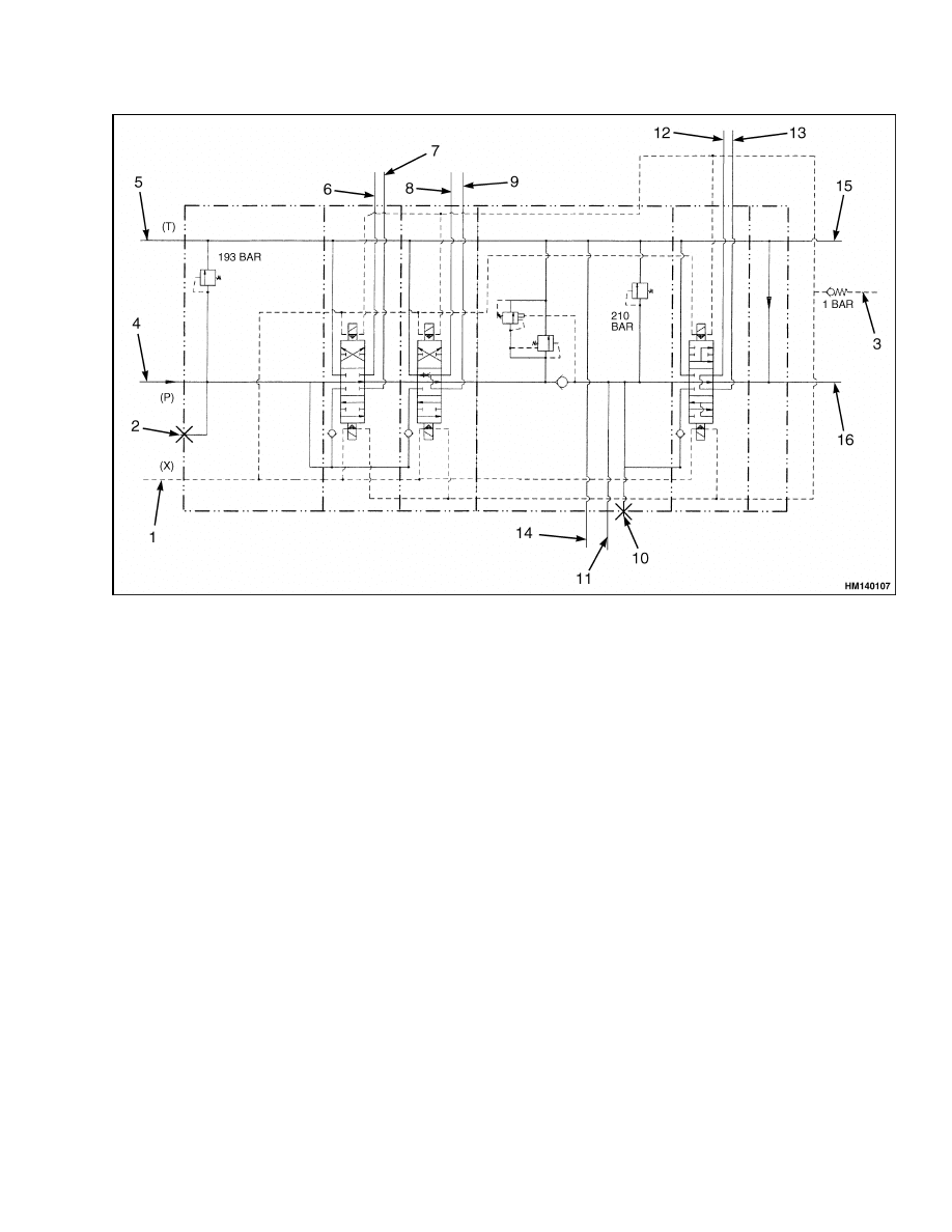
The main control valve controls the operation of the
lift, tilt, and auxiliary cylinders. See Figure 1, Fig-
ure 2, and Figure 3. The main control valve is fas-
tened to a plate in the frame, under the cab, and has
inlet and outlet sections. The valve is also divided
into a tilt/auxiliary section and a lift section. Both
inlet sections have a primary relief valve. The outlet
section of the tilt/auxiliary section contains an un-
loader valve.
Each section of the valve has a spool and valve body
and two electrical solenoids. On the fork lift truck the
control spools for the tilt and auxiliary are the same,
however a different type of spool is used in the lift
section of the valve. On trucks with empty container
handler the spools for tilt and auxiliary are different.
All spools have metering notches to improve the con-
trol of oil flow. When a control lever is operated, an
electrical signal is generated and activates electrical
solenoids at the end of a spool. As a result, hydraulic
pressure sets the spool. Each spool has springs that
return the spool to the NEUTRAL position as soon
as the control lever is released.
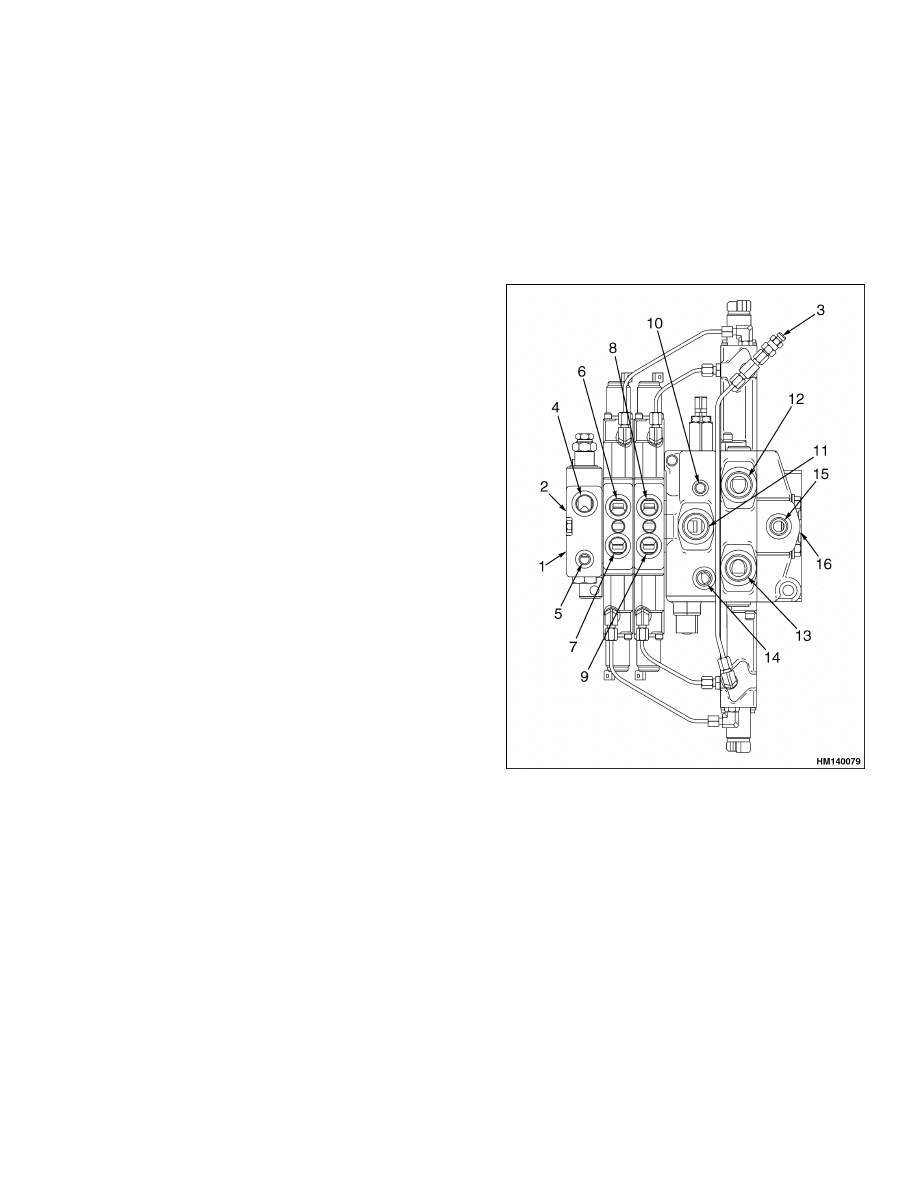
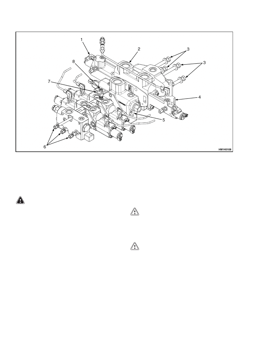
1.
PILOT INLET
2.
CHECK PORT
3.
BLEED LINE END
CAPS
4.
PUMP INLET
5.
TANK RETURN
6.
TILT CYLINDER
7.
TILT CYLINDER
8.
AUXILIARY
FUNCTIONS
9.
AUXILIARY
FUNCTIONS
10. CHECK PORT
11. PUMP INLET
12. LIFT CYLINDER
13. LIFT CYLINDER
14. TANK
15. TANK
16. MAIN OUTLET TO
TANK
Figure 1. Main Control Valve
1
Description
2000 SRM 943
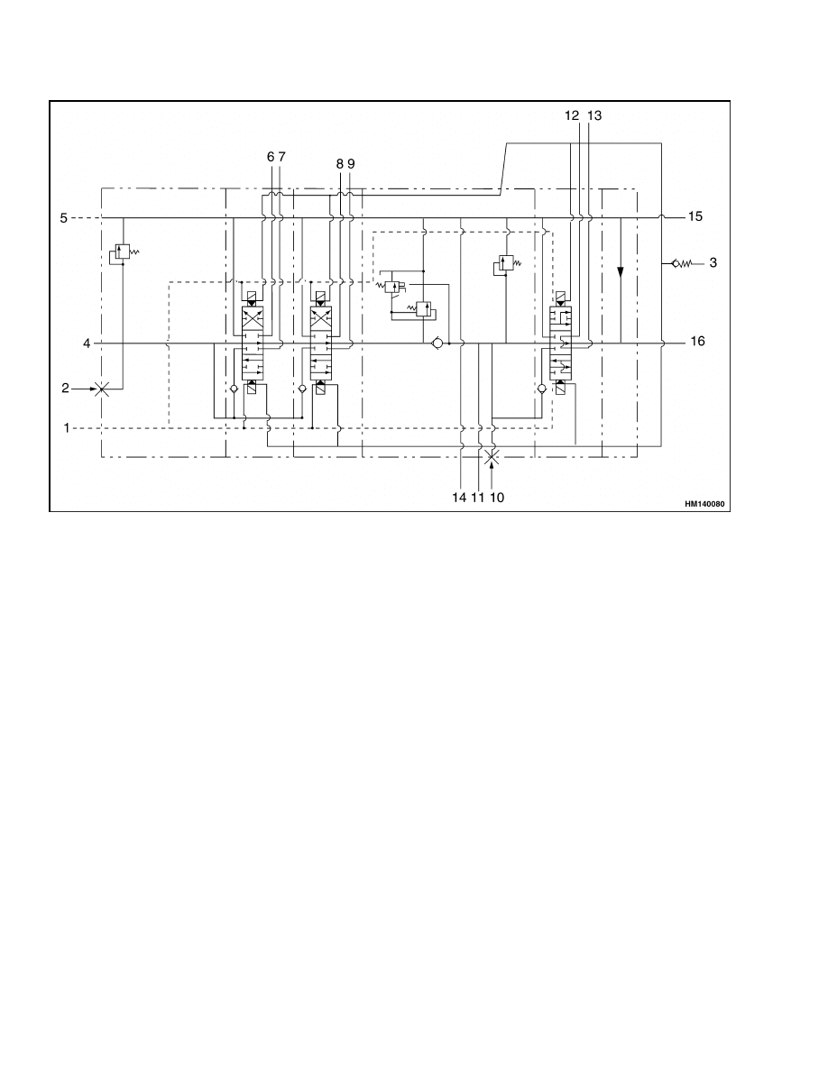
1.
PILOT (INLET)
2.
CHECK PORT
3.
BLEED LINE END CAPS
4.
PUMP INLET
5.
TANK
6.
TILT CYLINDER
7.
TILT CYLINDER
8.
AUXILIARY FUNCTIONS
9.
AUXILIARY FUNCTIONS
10. CHECK PORT
11. PUMP INLET
12. LIFT CYLINDER
13. LIFT CYLINDER
14. TANK
15. TANK
16. MAIN OUTLET TO TANK
Figure 2. FLT Main Control Valve Schematic
2
2000 SRM 943
Description
1.
PILOT (INLET)
2.
CHECK PORT
3.
BLEED LINE END CAPS
4.
PUMP INLET
5.
TANK
6.
TILT CYLINDER
7.
TILT CYLINDER
8.
AUXILIARY FUNCTIONS
9.
AUXILIARY FUNCTIONS
10. CHECK PORT
11. PUMP INLET
12. LIFT CYLINDER
13. LIFT CYLINDER
14. TANK
15. TANK
16. MAIN OUTLET TO TANK
Figure 3. ECH/FLT Main Control Valve Schematic, Fixed P & T
3

Operation
2000 SRM 943
Operation
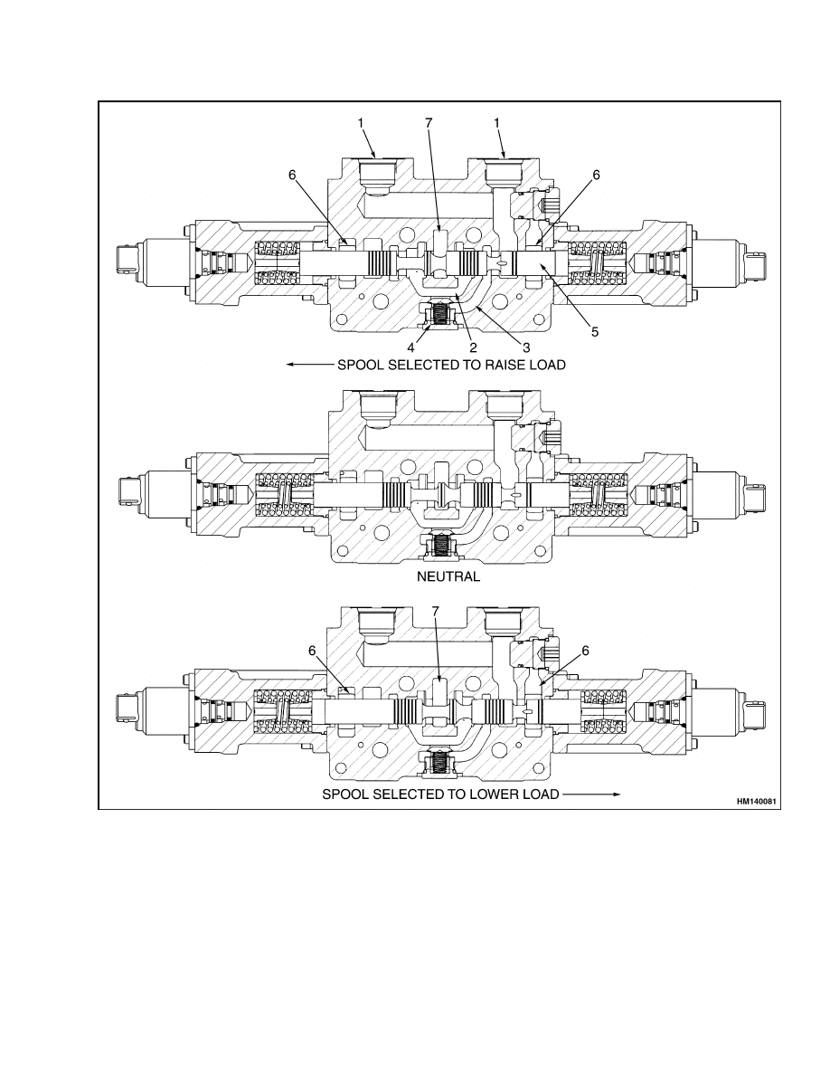
The main control valve controls the lift, lower, tilt,
and auxiliary functions. The valve has separate sec-
tions for each spool. In these valves, the spools can
be operated without preventing the flow of oil to the
other spools. The lift spool receives oil directly from
a tandem large pump and small pump, through the
tilt/auxiliary section. When the pressure demand in
the lift section is above 14 MPa (2030 psi), oil from
the small pump is diverted back to the tank.
This main control valve has three passages through
each section: the open-center passage, the parallel
passage, and the drain passage. See Figure 4 and
Figure 5. When the spools are in the NEUTRAL po-
sition, the oil flows through the open-center passage
and returns to the hydraulic tank. A spool makes a
restriction in the open-center passage when the spool
is moved from the NEUTRAL position. This restric-
tion causes an increase in pressure in the parallel
passage. This passage is common to all sections of
the valve, but oil cannot flow freely through it. The
pressure in the parallel passage causes the oil to flow
through a check valve into a supply cavity in the
valve body. The spool opens a path from the supply
cavity to the hydraulic cylinders to do work.
LIFT SECTION
Each port in the lift section of the control valve is con-
nected to a lift cylinder. See Figure 4. When the spool
is moved to the LIFT position, the spool makes a re-
striction in the open-center passage. The increased
pressure in the parallel passage causes oil to flow
through the check valve to the supply cavity.
NOTE:
The maximum mast speed, that can be ob-
tained, depends on the load.
When the required
operating pressure in the hydraulic system is less
than 14 MPa (2030 psi), the mast automatically lifts
within the high speed range. A description of the
two-speed lift system is in Hydraulic System 1900
SRM 938.
When the spool is in the LOWER position, the spool
opens the paths from the lift cylinders to the drain
cavity. The maximum LOWER speed is controlled
by the lower control valves in the lift cylinders. Oil
from the pump can flow through the open-center pas-
sage when the spool is in the LOWER position or the
NEUTRAL position. The NEUTRAL position of the
spool closes the passages to the ports for the lift cylin-
ders.
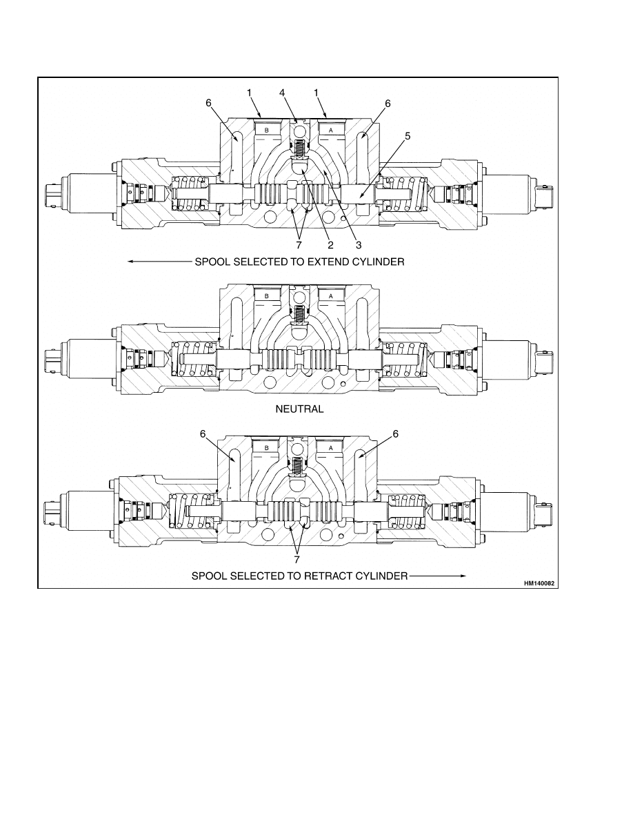
TILT/AUXILIARY SECTION
The operation of the tilt spool and the auxiliary spool
is the same. These spools control the direction of flow
in a hydraulic circuit for a cylinder or cylinders. The
cross section of the tilt section of the control valve
looks like Figure 5. When the tilt spool is moved
from NEUTRAL position, oil flows out of one port
in the valve section and returns through the other
port. When the supply cavity for one port is opened,
the other port is connected to the drain cavity.
NOTE: On each tilt control cylinder is a relief valve
that prevents cavitation in the tilt cylinders when the
mast is tilted forward with a load. See Hydraulic
System 1900 SRM 938 for a complete hydraulic sys-
tem diagram.
RELIEF VALVES
The relief valves limit the maximum pressure in the
hydraulic system. A relief valve for the lift circuit is
installed in the midinlet section of the main control
valve. A second relief valve is installed in the inlet
section for the tilt and auxiliary circuits. When the
pressure in a hydraulic circuit reaches the setting of
the relief valve, the valve opens a path between the
inlet and the tank.
UNLOADER VALVE
The unloader valve measures the pressure at the in-
let side of the lift section. If the pressure exceeds
14 MPa (2030 psi), the unloader valve diverts oil back
to the tank from the small pump.
4
2000 SRM 943
Operation
1.
PORT TO LIFT CYLINDER
2.
PARALLEL PASSAGE
3.
SUPPLY CAVITY
4.
CHECK VALVE
5.
LIFT/LOWER SPOOL
6.
DRAIN CAVITY
7.
OPEN-CENTER PASSAGE
Figure 4. Lifting and Lowering
5
Operation
2000 SRM 943
1.
PORT TO LIFT CYLINDER
2.
PARALLEL PASSAGE
3.
SUPPLY CAVITY
4.
CHECK VALVE
5.
LIFT/LOWER SPOOL
6.
DRAIN CAVITY
7.
OPEN-CENTER PASSAGE
Figure 5. Tilt and Auxiliary
6
2000 SRM 943
Main Control Valve Repair
Main Control Valve Repair
REMOVE
WARNING
Lower carriage completely before working on
control valve or hydraulic system.
Do not work under a raised carriage.
Put
mast in a vertical position and lower carriage
completely before disconnecting any parts of
hydraulic system.
The mast can lower sud-
denly and cause injury if the carriage is not
lowered. This procedure will make sure that
the carriage cannot lower suddenly and cause
injury or death.
Proceed as follows:
1.
Shut off engine.
2.
Turn key switch to ON position.
WARNING
Move all control levers back and forth a mini-
mum of 20 times to remove all hydraulic pres-
sure from pilot system.
3.
Turn the key switch to the OFF position.
4.
Tilt cab to access control valve. See the section
Operator’s Cab for your lift truck.
5.
Disconnect electric wires at spools of control
valve.
6.
Disconnect return hose at control valve. Keep
end of hose above hydraulic tank until a plug is
installed in hose. Tag lines and disconnect other
lines at control valve. Put caps on open lines and
plugs on ports.
NOTE:
Only remove the main control valve from
mounting plate when part to be repaired is not
accessible. Disassemble main control valve as nec-
essary for repairs. Most repairs are for replacement
of O-rings.
7.
Remove bolts that fasten control valve to mount-
ing plate and remove valve.
Clean outside of
valve before disassembly.
DISASSEMBLE
1.
To remove a spool, remove end cap from valve
section. Carefully pull spool from valve section.
Put tags on spools that are removed. Spools must
be installed in the sections from which they are
removed.
2.
Remove seal retainer for top of spool. Remove
O-rings and wipers from both ends of the section
of the valve.
3.
Remove auxiliary side and lift side as follows:
Auxiliary Side
CAUTION
Make sure to protect machined surfaces for
O-rings when the sections are separated. Small
defects can cause leaks.
1.
Remove Nyloc nut (8) and plate. See Figure 6.
2.
Remove nut (6) from the top through rod.
3.
Remove nuts (6) from the two bottom through
rods.
NOTE: The check valve and spring of each section
are held by the through rods. Keep each check valve
with the section in which it was installed.
4.
Carefully slide each section from the through
rods.
5.
Remove O-rings installed between sections.
NOTE: Do not try to repair a relief valve. Replace
relief valve that you cannot correctly adjust or that
has damage.
Lift Side
1.
Support lift side sections and remove the four
through bolts (3). See Figure 6 and Figure 7.
2.
Remove O-rings installed between sections.
7
Main Control Valve Repair
2000 SRM 943
1.
CHECK VALVE
2.
LIFT SECTION
3.
BOLTS
4.
OUTLET
5.
CENTER SECTION
6.
NUTS
7.
NUTPLATE
8.
NYLOC NUT
Figure 6. Main Control Valve
CLEAN AND INSPECT
WARNING
Cleaning solvents can be flammable and toxic
and cause skin irritation.
When cleaning
solvents are used, always follow the solvent
manufacturer’s recommended safety proce-
dures. Wear protective goggles or a face shield
to prevent eye injuries.
1.
Clean all parts of control valve with solvent.
Carefully dry parts with compressed air.
2.
Check spools and bores for defects. If a spool or
bore has damage, replace valve section that has
the damaged part or parts. Make sure that bores
and grooves for O-rings are smooth and do not
have dirt or defects.
3.
Check the check valves and relief valves for dam-
age. Replace valves as necessary.
ASSEMBLE
Auxiliary Side
CAUTION
Before installing parts in valve body, make
sure all parts are clean. Replace all seals and
O-rings.
Lubricate all parts with clean hy-
draulic oil during assembly.
CAUTION
Verify that nuts and rods torque specifications
are to the values listed. Incorrect torque values
may cause a malfunction of the spools.
1.
Install new seals in bore in each section. See
Figure 6.
2.
Install new O-rings between sections.
3.
Install check valves.
8
2000 SRM 943
Main Control Valve Repair
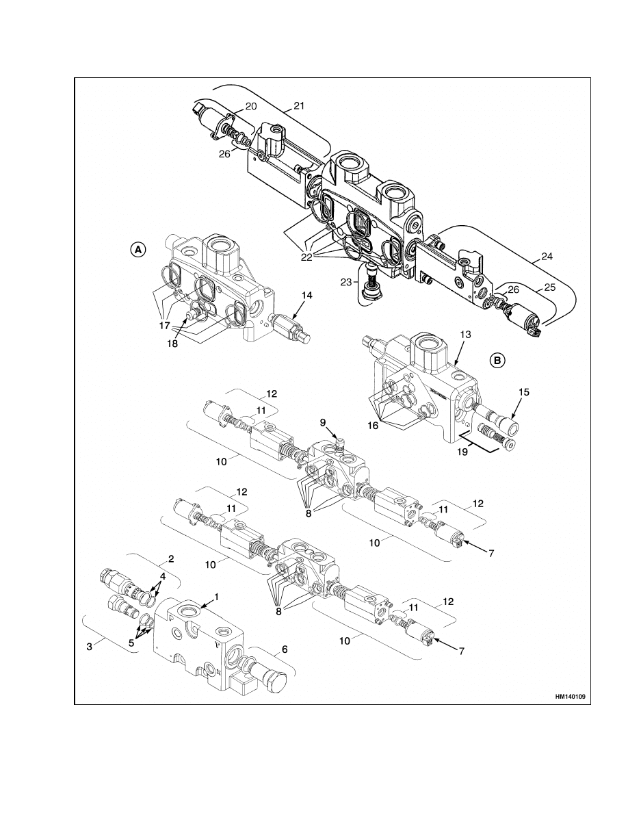
Figure 7. Main Control Valve Sections
9

Main Control Valve Repair
2000 SRM 943
Legend for Figure 7
A. OUTLET VIEW OF CENTER SECTION
B. INLET VIEW OF CENTER SECTION
1.
INLET SECTION
2.
SECONDARY RELIEF VALVE
3.
ADAPTOR
4.
RELIEF VALVE SEALS
5.
CARTRIDGE SEALS
6.
PRESSURE VALVE
7.
VALVE
8.
INTERFACE SEAL KIT
9.
CHECK VALVE
10. END CAP
11. SEAL KIT
12. SOLENOID
13. CENTER SECTION
14. RELIEF VALVE
15. CARTRIDGE
16. INTERFACE SEAL KIT
17. INTERFACE SEAL KIT
18. CHECK VALVE
19. PISTON
20. SOLENOID
21. END CAP ASSEMBLY
22. SOLENOID SEALS
23. SOLENOID
24. END CAP ASSEMBLY
25. DROP SOLENOID
26. SOLENOID SEAL KIT
4.
Slide sections over the three through rods (6).
5.
Install nuts, finger tight, on the three through
rods.
6.
Torque the three nuts.
Top nut to 40 N•m
(29.5 lbf ft) and the two bottom nuts to 27 N•m
(20 lbf ft). Use sequence top, bottom left, bottom
right, and top.
NOTE: When installing a replacement through rod,
or tightening of a loose through rod is required,
torque through rod to 25 N•m (18.5 lbf ft).
7.
Install plate and nyloc nut. Torque to 15 N•m
(11 lbf ft).
8.
Install springs.
9.
Lubricate spools with clean hydraulic oil. Make
sure that dirt does not get on any of the parts.
Carefully install spools in valve body. Make sure
that spools move freely in bores. Install seal re-
tainers and end caps.
Lift Side
CAUTION
Before installing parts in valve body, make
sure all parts are clean. Replace all seals and
O-rings.
Lubricate all parts with clean hy-
draulic oil during assembly.
CAUTION
Verify that bolt torque specifications are to
the values listed. Incorrect torque values may
cause a malfunction of the spools.
1.
Install new seals in bore in each section. See
Figure 6.
2.
Install new O-rings between sections.
3.
Install check valves.
4.
Assemble sections, finger tight, using the four
through bolts (3).
5.
Torque the four through bolts to 101.5 N•m
(75 lbf ft). Use sequence top left, bottom right,
top right, and bottom left.
6.
Install springs.
7.
Lubricate spools with clean hydraulic oil. Make
sure that dirt does not get on any of the parts.
Carefully install spools in valve body. Make sure
that spools move freely in bores. Install seal re-
tainers and end caps.
INSTALL
1.
Install control valve on mounting plate in frame.
2.
Connect electrical cables at solenoids.
3.
Connect hydraulic lines to control valve. Connect
return line after connecting other lines.
4.
Add clean hydraulic oil to tank.
For correct
specifications, see the section Periodic Main-
tenance for your lift truck.
10
2000 SRM 943
Pressure Relief Valve Check and Adjustment
WARNING
Do not try to locate hydraulic leaks by putting
hands on pressurized hydraulic components.
Hydraulic oil can be injected into the body by
pressure.
5.
Operate hydraulic system and check for leaks
and correct operation. Adjust relief valves as de-
scribed in Pressure Relief Valve Check and Ad-
justment.
Pressure Relief Valve Check and Adjustment
CHECK AND ADJUST
1.
If engine is operating, stop engine. Connect a 0
to 25 MPa (0 to 3625 psi) gauge to test port. Test
port is on inlet section of main control valve.
CAUTION
Do not remove cap/adjustment nut on relief
valve. The cap/adjustment nut is the adjust-
ment for relief pressure and the retainer for a
sleeve, shims, spring, and poppet.
2.
Hold cap/adjustment nut on relief valve and
loosen jam nut.
3.
Start engine.
Operate hydraulic system until
temperature of hydraulic oil is 55 to 65 C (130 to
150 F). Run engine at maximum rpm when mak-
ing pressure checks.
4.
Check relief valve in the lift section by raising
mast until it stops. Check the relief valve in the
tilt/auxiliary section by raising the mast to a po-
sition whereby the mast can be fully tilted for-
ward without touching the ground. Tilt mast for-
ward until it stops. Hold appropriate lever and
read gauge when relief valve opens.
WARNING
The cap/adjustment nut holds parts that can
cause injury if released when the system has
pressure.
DO NOT remove cap/adjustment
nut.
Only turn cap/adjustment nut a small
amount for each check. Move cap/adjustment
nut 0.08 mm (0.003 in.) to change relief pres-
sure approximately 690 kPa (100 psi).
The
cap/adjustment nut has minimum thread en-
gagement at a setting of approximately 6.9 MPa
(1000 psi).
5.
To change the setting, slowly turn cap/adjust-
ment nut as necessary. See Specifications for cor-
rect setting. If the cap/adjustment nut is tight
against housing, pressure cannot be increased
further.
Replace relief valve.
Loosen cap/ad-
justment nut to decrease pressure. When ad-
justment is correct, hold cap/adjustment nut and
tighten jam nut to 55 to 67 N•m (40 to 50 lbf ft).
6.
Remove gauge when checks are complete.
REPLACE
NOTE: Do not try to repair a relief valve. Replace
relief valve that cannot be correctly adjusted or that
has been damaged.
WARNING
Move all control levers back and forth a mini-
mum of 20 times to remove all hydraulic pres-
sure from the system.
1.
Shut off engine.
2.
Turn the key switch to the ON position.
3.
Turn the key switch to the OFF position.
4.
Tilt cab to access control valve. See the section
Operator’s Cab for your lift truck.
5.
Remove relief valve. Use wrench on body of relief
valve.
6.
Install new relief valve assembly. Use wrench on
body of valve and tighten to 81 to 108 N•m (60 to
80 lbf ft).
7.
Adjust relief pressure settings for the hydraulic
system as described in this section.
11

Troubleshooting
2000 SRM 943
Specifications
Unit
Relief Valve Settings
Relief Valve - Lift Section
21.0 MPa (3050 psi)
Relief Valve - Tilt/Auxiliary Section
19.3 MPa (2807 psi)
Troubleshooting
PROBLEM
POSSIBLE CAUSE
PROCEDURE OR ACTION
Oil leaks at the end caps of
the spools.
End cap seals have defects.
Replace seals.
Spool has a defect.
Replace defective spool.
Valve body has a defect.
Replace control valve section.
Spool will not move.
No pilot pressure.
Check and repair pilot valve and/or
priority valve, if necessary.
Dirt between spool and bore.
Clean valve as necessary.
Spool is bent or damaged.
Replace defective spool.
No electrical signal.
Check electrical system and repair.
Through bolts, or nuts on through
rods, not at correct torque specifica-
tions
Tighten or loosen through bolts to
correct torque specifications
Spool will not return to
NEUTRAL.
Calibration of levers or joystick not
to specifications.
Recalibrate levers or joystick.
Return spring is damaged.
Replace damaged spring.
Dirt between spool and bore.
Clean valve as necessary.
Spool is bent or damaged.
Replace defective spool.
Cylinders move slowly or do
not move.
Pressure relief valve has a defect.
Repair or adjust relief valve.
Large leaks between spool and bore.
Replace control valve section.
Hydraulic pump has a defect.
Repair or replace hydraulic pump.
Air is in hydraulic system.
Remove air from hydraulic system.
Restriction in hydraulic lines.
Repair or replace hydraulic lines.
12

2000 SRM 943
Troubleshooting
PROBLEM
POSSIBLE CAUSE
PROCEDURE OR ACTION
Cylinders move slowly or do
not move. (Cont.)
Load is greater than capacity.
Handle only correct load.
Cylinder seal has defects.
Repair or replace cylinder.
Fast lift speed function does
not operate.
Low pilot pressure.
Check and repair pilot valve.
Defective unloader valve.
Check and repair or replace unloader
valve.
Calibration of levers or joystick not
to specification.
Recalibrate levers or joystick.
Hydraulic pressure is high.
Pressure relief valve has a defect.
Repair or replace relief valve.
Pressure relief valve is not adjusted
correctly.
Adjust relief valve.
Restriction in return line.
Replace hydraulic line.
Tilt cylinders extend when
tilt spool is in NEUTRAL
position.
Cylinder seal has defects.
Repair cylinder.
Hydraulic lines have leaks.
Replace hydraulic lines.
Oil leaks between control valve spool
and bore, and tilt relief valve has a
defect.
Repair main control valve and relief
valve.
Calibration of levers or joystick not
to specification.
Recalibrate levers or joystick.
Tilt cylinders extend sud-
denly when tilt spool is
moved to BACK TILT posi-
tion.
Check valve to determine if tilt spool
has a defect, and/or tilt relief valve
has a defect.
Replace spool or relief valve if neces-
sary.
Delay occurs between com-
mand and movement.
Pilot return line or 1 bar check valve
is blocked.
Repair or replace hydraulic lines.
13

Troubleshooting
2000 SRM 943
PROBLEM
POSSIBLE CAUSE
PROCEDURE OR ACTION
Tilt cylinders extend sud-
denly when tilt lever is
moved to FORWARD TILT
position.
Tilt relief valve has a defect.
Repair or adjust relief valve.
Lift cylinders retract when
lift lever is in NEUTRAL
position.
Check valve for lift spool has a defect.
Replace check valve.
Cylinder seal has defects.
Repair cylinder.
Hydraulic lines have leaks.
Replace hydraulic lines.
Oil leaks between lift spool and bore.
Repair main control valve.
Calibration of levers or joystick not
to specification.
Recalibrate levers or joystick.
14


TECHNICAL PUBLICATIONS
2000 SRM 943
9/03 (5/02)(2/01)(2/95)(12/90)(7/89) Printed in United Kingdom
Document Outline
- toc
Wyszukiwarka
Podobne podstrony:
1494953 1400SRM0944 (09 2003) UK EN
897394 1900SRM0453 (09 2003) UK EN
1498445 1400SRM0945 (09 2003) UK EN
1510463 1400SRM0984 (09 2003) UK EN
1466211 2000SRM0754 (12 2003) UK EN
897987 1800SRM0659 (09 2003) UK EN
897110 1900SRM0328 (09 2003) UK EN
897993 1600SRM0671 (09 2003) UK EN
897391 1400SRM0450 (09 2003) UK EN
897392 1600SRM0451 (09 2003) UK EN
1466235 1600SRM0733 (09 2003) UK EN
910073 1400SRM0049 (09 2003) UK EN
1466247 1400SRM0731 (09 2003) UK EN
1466223 1900SRM0753 (09 2003) UK EN
897113 8000SRM0331 (09 2003) UK EN
1524437 8000SRM1035 (09 2003) UK EN
1494140 1600SRM0936 (09 2003) UK EN
więcej podobnych podstron