TILT CYLINDERS
H3.50-5.50XM (H70-120XM) [K005, L005]
PART NO. 1466205
2100 SRM 735

SAFETY PRECAUTIONS
MAINTENANCE AND REPAIR
• When lifting parts or assemblies, make sure all slings, chains, or cables are correctly
fastened, and that the load being lifted is balanced. Make sure the crane, cables, and
chains have the capacity to support the weight of the load.
• Do not lift heavy parts by hand, use a lifting mechanism.
• Wear safety glasses.
• DISCONNECT THE BATTERY CONNECTOR before doing any maintenance or repair
on electric lift trucks. Disconnect the battery ground cable on internal combustion lift
trucks.
• Always use correct blocks to prevent the unit from rolling or falling. See HOW TO PUT
THE LIFT TRUCK ON BLOCKS in the Operating Manual or the Periodic Mainte-
nance section.
• Keep the unit clean and the working area clean and orderly.
• Use the correct tools for the job.
• Keep the tools clean and in good condition.
• Always use HYSTER APPROVED parts when making repairs. Replacement parts
must meet or exceed the specifications of the original equipment manufacturer.
• Make sure all nuts, bolts, snap rings, and other fastening devices are removed before
using force to remove parts.
• Always fasten a DO NOT OPERATE tag to the controls of the unit when making repairs,
or if the unit needs repairs.
• Be sure to follow the WARNING and CAUTION notes in the instructions.
• Gasoline, Liquid Petroleum Gas (LPG), Compressed Natural Gas (CNG), and Diesel fuel
are flammable. Be sure to follow the necessary safety precautions when handling these
fuels and when working on these fuel systems.
• Batteries generate flammable gas when they are being charged. Keep fire and sparks
away from the area. Make sure the area is well ventilated.
NOTE: The following symbols and words indicate safety information in this
manual:
WARNING
Indicates a condition that can cause immediate death or injury!
CAUTION
Indicates a condition that can cause property damage!

Tilt Cylinders
Table of Contents
TABLE OF CONTENTS
General ...............................................................................................................................................................
Description .........................................................................................................................................................
Tilt Cylinder Repair ...........................................................................................................................................
Remove ...........................................................................................................................................................
Disassemble ...................................................................................................................................................
Clean ..............................................................................................................................................................
Inspect ............................................................................................................................................................
Assemble ........................................................................................................................................................
Install .............................................................................................................................................................
Tilt Cylinder Leak Check ..................................................................................................................................
Tilt Cylinder Stroke and Mast Tilt Angle Adjustment ....................................................................................
Troubleshooting..................................................................................................................................................
This section is for the following models:
H3.50-5.50XM (H70-120XM) [K005, L005]
©2004 HYSTER COMPANY
i

"THE
QUALITY
KEEPERS"
HYSTER
APPROVED
PARTS
2100 SRM 735
Tilt Cylinder Repair
General
This section has the description and repair procedures for the tilt cylinders.
Description
The tilt cylinders (Figure 1 and Figure 2) are used
to move the mast forward and backward. When the
cylinder rod is extended (tilted forward), oil enters
the tilt cylinder port behind the piston. The oil pres-
sure pushes the cylinder rod out of the cylinder. Oil
in front of the piston returns to the hydraulic tank.
When the cylinder rod is retracted (tilted backward),
the oil enters the port in front of the piston. The oil
pressure pushes the cylinder rod into the tilt cylin-
der. The oil behind the piston returns to the hy-
draulic tank.
Tilt Cylinder Repair
REMOVE
1.
Remove mast as described in the section Masts,
Description and Repairs 4000 SRM 736. Re-
move the floor plate.
2.
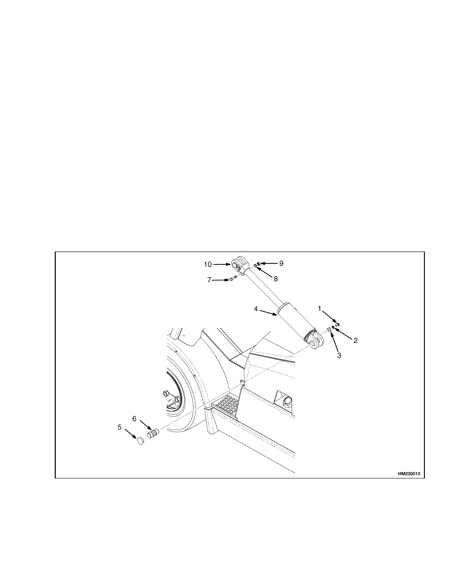
Disconnect the hydraulic lines at the tilt cylinder.
Install caps on the hydraulic lines and plugs in
the tilt cylinder. See Figure 1.
1.
CAPSCREW
2.
WASHER
3.
RETAINING PIN
4.
TILT CYLINDER
5.
CAP
6.
ANCHOR PIN
7.
CAPSCREW (ROD END)
8.
LOCKWASHER (ROD END)
9.
NUT (ROD END)
10. ROD END
Figure 1. Tilt Cylinders
1
Tilt Cylinder Repair
2100 SRM 735
WARNING
Do not push the anchor pins out of the rod end
with your fingers.
Do not permit the tilt cylinders to drop and
cause damage to them.
3.
Remove the cap in the frame. Remove the an-
chor pin. Remove the tilt cylinder through the
front of the lift truck. Rotate the cylinder during
removal to protect plugs. Remove the capscrew
and washer connecting the retaining pin to the
tilt cylinder. Remove the retaining pin.
4.
Remove the capscrew, washer, and nut fastening
the rod end to the rod. Remove the rod end from
the rod.
DISASSEMBLE
1.
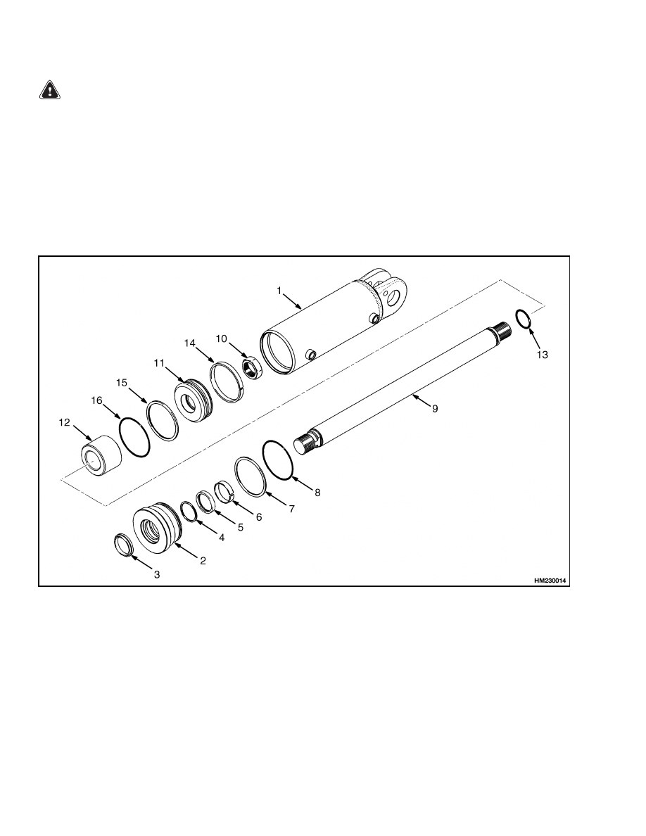
Put the clevis end of the cylinder in a vise with
soft jaws. See Figure 2. Remove the gland from
the cylinder. Remove the rod wiper, rod seal, and
backup rings from the gland. Remove the wear
ring and O-ring from the gland. Discard the rod
seal and O-ring.
2.
Remove the rod and piston from the cylinder.
1.
CYLINDER SHELL
2.
GLAND
3.
ROD WIPER
4.
BACKUP RING
5.
ROD SEAL
6.
WEAR RING
7.
BACKUP RING
8.
O-RING
9.
ROD
10. PREVAILING TORQUE LOCK NUT
11. PISTON
12. SPACER
13. O-RING
14. GUIDE RING
15. PISTON SEAL RING
16. O-RING
Figure 2. Tilt Cylinders
2

2100 SRM 735
Tilt Cylinder Repair
NOTE: Spacer is not used on tilt cylinders with 12-de-
gree forward or backward tilt.
3.
If the piston is to be removed for replacement, put
rod in a vise with soft jaws. Remove and discard
the prevailing torque lock nut if damaged. Re-
move the spacer if present from the rod. Remove
and discard the O-ring from the rod. Remove the
guide ring from the piston. Remove and discard
the piston seal ring and O-ring from the piston.
CLEAN
WARNING
Cleaning solvents can be flammable and toxic
and can cause skin irritation.
When using
cleaning solvents, always follow the solvent
manufacturer’s recommended safety proce-
dures.
Compressed air can move particles so that they
cause injury to the user or to other personnel.
Make sure that the path of the compressed air
is away from all personnel.
Wear protective
goggles or a face shield to prevent injury to the
eyes.
Clean all parts in solvent and dry with compressed
air.
INSPECT
Inspect all parts and replace any parts that are worn
or damaged.
ASSEMBLE
NOTE: Always use new seals and O-rings. Make sure
all parts are clean. Apply packing lubricant to seals,
rings, and wipers prior to assembly.
NOTE: Spacer is not used on tilt cylinders with 12-de-
gree forward or backward tilt.
1.
Install piston seal ring, O-ring, and guide ring
on the piston. See Figure 2. Install the O-ring on
the rod. If removed, install spacer and piston on
the rod.
NOTE: If the piston was not removed, retighten the
prevailing torque nut to 400 to 440 N•m (296 to
326 lbf ft).
2.
Put rod in a vise with soft jaws. If the prevail-
ing torque lock nut was removed, install a new
prevailing torque lock nut and tighten the lock
nut on the piston rod to 400 to 440 N•m (296
to 326 lbf ft). Insert the rod and piston into the
cylinder.
3.
Install rod seal, backup rings, wear ring, O-ring,
and rod wiper on the gland.
4.
Put cylinder in a vise with soft jaws. Slide gland
onto piston and fasten to cylinder. Tighten gland
to 400 to 500 N•m (296 to 370 lbf ft).
5.
Install rod end onto rod with capscrew, washer,
and nut. Tighten the capscrew on the rod to 66
to 73 N•m (49 to 54 lbf ft).
INSTALL
1.
Insert cylinder through front of lift truck. Rotate
cylinder during insertion to protect plugs. See
Figure 1.
2.
Install anchor pin. Install the retaining pin. Fas-
ten retaining pin to tilt cylinder using a capscrew
and washer. Tighten capscrew to 66 to 73 N•m
(49 to 54 lbf ft). Insert the tilt cylinder in frame.
3.
Connect the hydraulic lines to the tilt cylinder.
4.
Install the floor plate. Attach mast as described
in the section Masts, Description and Repairs
4000 SRM 736.
5.
Operate the tilt cylinders. Check for correct op-
eration and leakage. Adjust the tilt cylinders
as described in Tilt Cylinder Leak Check and
Tilt Cylinder Stroke and Mast Tilt Angle Adjust-
ment.
3

Troubleshooting
2100 SRM 735
Tilt Cylinder Leak Check
WARNING
Never allow anyone under a raised carriage.
Do not put any part of your body in or through
the lift mechanism unless all parts of the mast
are completely lowered and the engine is
STOPPED.
Do not try to find hydraulic leaks by putting
your hand on hydraulic components under
pressure.
Hydraulic oil can be injected into
the body by the pressure.
1.
Put a capacity load on the forks. Use a safety
chain to hold the load to the carriage. Raise the
load approximately 2.5 m (8 ft). Put the mast in
a vertical position.
2.
Maintain a hydraulic oil temperature of 20 C
(68 F). Measure the distance that the rod for
the tilt cylinder extends from the shell. Mea-
sure the distance the rod moves in ten minutes.
The difference in measurements is the actual
movement. The maximum movement allowed is
13 mm (0.5 in.).
3.
Maintain a hydraulic oil temperature of 60 C
(140 F). Measure the distance that the rod for
the tilt cylinder extends from the shell. Mea-
sure the distance the rod moves in ten minutes.
The difference in measurements is the actual
movement. The maximum movement allowed is
89 mm (3.4 in.).
4.
If the actual movement is greater than the maxi-
mum movement allowed, lower the mast and re-
move the load from the forks. Install a valve be-
tween the port at the front of the tilt cylinder
and the hydraulic line. Put the load on the forks
again. Close the valve. Tilt the mast forward just
past the vertical position. If the mast continues
to tilt slowly forward, the seals on the piston are
leaking.
5.
If the mast does not move, open the gate valve
and check the movement again.
If the mast
moves forward when the gate valve is open,
check for leaks in the hydraulic lines and fit-
tings. If no leaks are found, the main control
valve can be worn or damaged. Remove the load
from the forks when the checks are complete.
Tilt Cylinder Stroke and Mast Tilt Angle Adjustment
Adjust the tilt cylinders as described in the section Mast Masts, Description and Repairs 4000 SRM 736.
Troubleshooting
PROBLEM
POSSIBLE CAUSE
PROCEDURE OR ACTION
Tilt cylinder movement is
slow or not smooth.
Air is in the hydraulic system.
Remove air from hydraulic system.
The hydraulic pump is worn or dam-
aged.
Repair or replace hydraulic pump.
Restriction in the hydraulic lines.
Repair hydraulic lines.
Seals in tilt cylinder are damaged.
Replace seals and inspect cylinder
bore for damage.
Tilt cylinders have internal damage.
Repair or replace cylinder.
Load is greater than capacity.
Reduce load.
4

2100 SRM 735
Troubleshooting
PROBLEM
POSSIBLE CAUSE
PROCEDURE OR ACTION
Tilt cylinder movement is
slow or not smooth. (Cont.)
Large leaks between spool and bore.
Replace valve section.
Spool is not fully extended or re-
tracted.
Adjust linkage to spool.
Tilt control spool is damaged.
Repair control valve.
The tilt cylinders permit the
mast to move when the Tilt
control lever is in the Neu-
tral position.
There are leaks in the hydraulic
lines.
Tighten fittings or repair leaks.
Seals in tilt cylinder are damaged.
Replace seals and inspect cylinder
bore for damage.
Tilt cylinders have internal damage.
Repair or replace cylinder.
Tilt control spool is damaged.
Repair control valve.
5

NOTES
____________________________________________________________
____________________________________________________________
____________________________________________________________
____________________________________________________________
____________________________________________________________
____________________________________________________________
____________________________________________________________
____________________________________________________________
____________________________________________________________
____________________________________________________________
____________________________________________________________
____________________________________________________________
____________________________________________________________
____________________________________________________________
____________________________________________________________
____________________________________________________________
____________________________________________________________
____________________________________________________________
____________________________________________________________
____________________________________________________________
6


TECHNICAL PUBLICATIONS
2100 SRM 735
11/04 (9/03)(9/02)(8/99) Printed in United Kingdom
Document Outline
Wyszukiwarka
Podobne podstrony:
1510469 2100SRM0986 (11 2004) UK EN
1554636 8000SRM1080 (11 2004) UK EN
1554631 2000SRM1085 (03 2004) UK EN
1564283 1900SRM1107 (01 2004) UK EN
1452929 2200SRM0679 (11 2003) UK EN
1554635 8000SRM1079 (06 2004) UK EN
897506 4000SRM0521 (05 2004) UK EN
897480 1400SRM0499 (10 2004) UK EN
897067 1400SRM0285 (05 2004) UK EN
1565454 8000SRM1113 (06 2004) UK EN
1538373 2200SRM1065 (02 2004) UK EN
897393 1800SRM0452 (02 2004) UK EN
1470232 1900SRM0783 (01 2004) UK EN
897493 1600SRM0512 (11 1995) UK EN
910460 1600SRM0258 (05 2004) UK EN
1559550 2200SRM1097 (10 2004) UK EN
więcej podobnych podstron