HUSCO™ MAIN
CONTROL VALVE
J1.60-2.00XMT (J30-40ZT) [J160]
PART NO. 1554631
2000 SRM 1085

SAFETY PRECAUTIONS
MAINTENANCE AND REPAIR
• When lifting parts or assemblies, make sure all slings, chains, or cables are correctly
fastened, and that the load being lifted is balanced. Make sure the crane, cables, and
chains have the capacity to support the weight of the load.
• Do not lift heavy parts by hand, use a lifting mechanism.
• Wear safety glasses.
• DISCONNECT THE BATTERY CONNECTOR before doing any maintenance or repair
on electric lift trucks. Disconnect the battery ground cable on internal combustion lift
trucks.
• Always use correct blocks to prevent the unit from rolling or falling. See HOW TO PUT
THE LIFT TRUCK ON BLOCKS in the Operating Manual or the Periodic Mainte-
nance section.
• Keep the unit clean and the working area clean and orderly.
• Use the correct tools for the job.
• Keep the tools clean and in good condition.
• Always use HYSTER APPROVED parts when making repairs. Replacement parts
must meet or exceed the specifications of the original equipment manufacturer.
• Make sure all nuts, bolts, snap rings, and other fastening devices are removed before
using force to remove parts.
• Always fasten a DO NOT OPERATE tag to the controls of the unit when making repairs,
or if the unit needs repairs.
• Be sure to follow the WARNING and CAUTION notes in the instructions.
• Gasoline, Liquid Petroleum Gas (LPG), Compressed Natural Gas (CNG), and Diesel fuel
are flammable. Be sure to follow the necessary safety precautions when handling these
fuels and when working on these fuel systems.
• Batteries generate flammable gas when they are being charged. Keep fire and sparks
away from the area. Make sure the area is well ventilated.
NOTE:
The following symbols and words indicate safety information in this
manual:
WARNING
Indicates a condition that can cause immediate death or injury!
CAUTION
Indicates a condition that can cause property damage!

HUSCO™ Main Control Valve
Table of Contents
TABLE OF CONTENTS
General ...............................................................................................................................................................
Description .........................................................................................................................................................
Operation............................................................................................................................................................
Lift Section .....................................................................................................................................................
Tilt Section .....................................................................................................................................................
Tilt Backward ............................................................................................................................................
Tilt Forward...............................................................................................................................................
Relief Valve ....................................................................................................................................................
Main Control Valve Repair ................................................................................................................................
Remove ...........................................................................................................................................................
Disassemble ...................................................................................................................................................
Clean and Inspect ..........................................................................................................................................
Assemble ........................................................................................................................................................
Install .............................................................................................................................................................
Pressure Relief Valve Check and Adjustment..................................................................................................
Primary Relief Valve......................................................................................................................................
Secondary Relief Valve ..................................................................................................................................
Troubleshooting..................................................................................................................................................
This section is for the following models:
J1.60-2.00XMT (J30-40ZT) [J160]
©2004 HYSTER COMPANY
i

"THE
QUALITY
KEEPERS"
HYSTER
APPROVED
PARTS

2000 SRM 1085
Operation
General
This section has a description and the repair procedures for the main control valve and the linkage arrange-
ment.
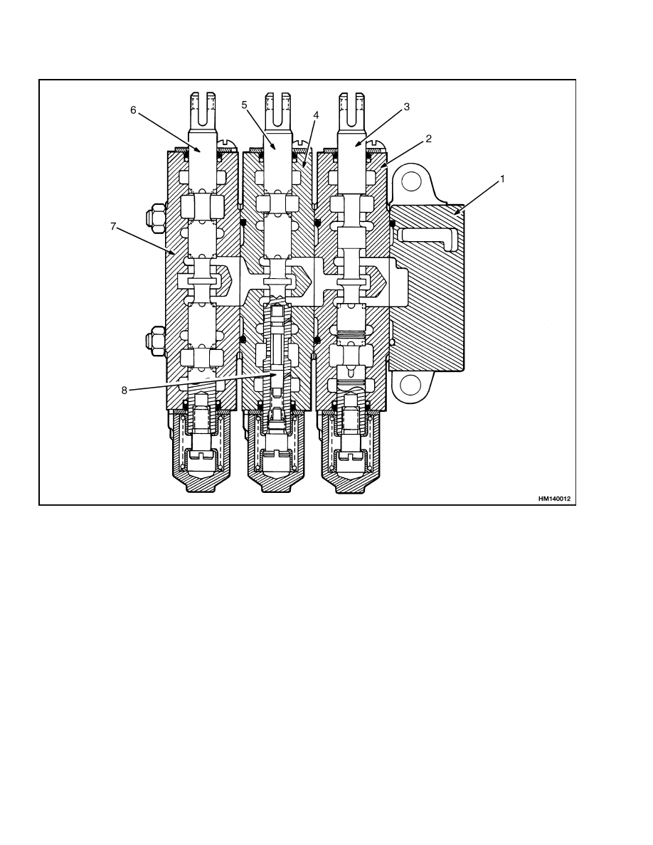
Description
The main control valve controls the operation of the
lift, tilt, and auxiliary cylinders. The main control
valve is installed to the right of the operator, at the
level of the floor plate. The main control valve has
the following sections (see Figure 1):
• Inlet section with the primary relief valve
• Lift and lower section
• Tilt section
• Auxiliary section(s) with the secondary relief valve
The sections are held together with three through-
bolts.
Each function of the main control valve is made as a
separate section having a spool and valve body. Each
valve body casting is the same. The control spools are
different for each function. Other sections are added
to the main control valve to control optional auxiliary
functions.
Each spool has a spring that returns the spool to the
neutral position when the control lever is released.
Each valve section has a check valve in the valve
body. The check valve and spring are held in the
valve body by the next section.
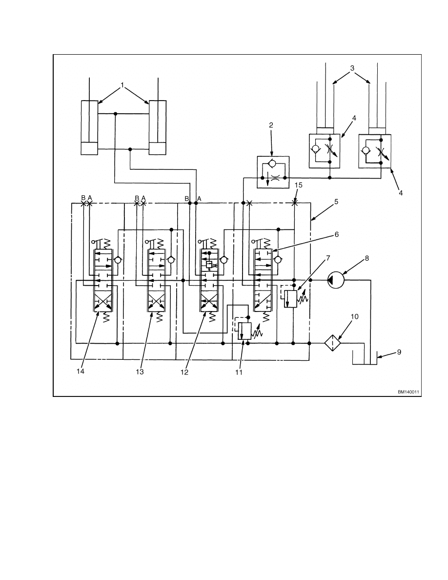
Operation
The main control valve is an open-center, parallel
circuit valve. When open-center valve spools are in
the neutral position, the hydraulic oil flows through
the valve with minimum restriction. The oil returns
through the drain passage and returns to the hy-
draulic tank. Except during lifting, each spool can
be operated without preventing the flow of oil to an-
other spool.
This valve has three parallel passages through the
valve. See Figure 2. When the spools are in the
neutral position, the oil flows through the open cen-
ter passage. At the end of the valve, the oil returns
through the drain passage and returns to the hy-
draulic tank. When a spool is moved from the neu-
tral position, it makes a restriction in the open-center
passage. This restriction causes an increase in pres-
sure in the parallel passage. The parallel passage
is common to all sections of the valve, but oil can-
not flow freely through it. The increased pressure in
the parallel passage causes the oil to flow through
a check valve into a supply cavity in the valve body.
The spool gives a path from the supply cavity to the
hydraulic cylinder to do work.
The first lever to the right of the operator controls
the lifting and lowering of the mast. Move the lever
forward to lower the mast. Pull the lever back to lift
the mast. The second lever controls the tilt function.
Move the lever forward to tilt the mast forward. Pull
the lever back to tilt the mast back. The optional
third control lever is for attachments and has two
methods of operation depending on the attachment.
• Control Lever With Detent – Required for At-
tachments With a Clamp Action: The lever is
spring-loaded toward the operator. The lever is op-
erated by moving it to the right, then forward or
backward.
• Control Lever Without a Detent – Attach-
ments Without a Clamp Action: The lever is
operated by moving forward or backward.
The optional fourth control lever has a detent and
is spring-loaded toward the operator. The lever is
operated by moving it to the right, then forward or
backward.
Each of the control levers actuate a mechanical
switch for the hydraulic pump. Movement of the tilt
or auxiliary levers in either direction causes a switch
to start the hydraulic pump. The lift/lower control
lever actuates its switch only in the lift position.
1
Operation
2000 SRM 1085
1.
INLET SECTION
2.
LIFT SECTION
3.
LIFT/LOWER SPOOL
4.
TILT SECTION
5.
TILT SPOOL
6.
AUXILIARY SPOOL
7.
AUXILIARY SECTION
8.
TILT CONTROL SPOOL
Figure 1. Main Control Valve
2
2000 SRM 1085
Operation
A. UPPER PORT
B. LOWER PORT
1.
TILT CYLINDER
2.
LOWERING CONTROL VALVE (EXTERNAL)
3.
LIFT CYLINDER
4.
LOWERING CONTROL VALVE (INTERNAL)
5.
MAIN CONTROL VALVE
6.
LIFT/LOWER SPOOL
7.
PRIMARY RELIEF VALVE
8.
HYDRAULIC PUMP
9.
HYDRAULIC TANK
10. FILTER
11. SECONDARY RELIEF VALVE
12. TILT SPOOL
13. AUXILIARY SPOOL
14. AUXILIARY SPOOL
15. SUPPLY PRESSURE TEST PORT
Figure 2. Control Valve Schematic
3
Operation
2000 SRM 1085
LIFT SECTION
When the spool is in the Lower position, the spool
opens a path from the lift cylinders to the drain cav-
ity. See Figure 3. The spool is made so the open cen-
ter passage has no restriction.
When the spool is moved to the Lift position, the spool
makes a restriction in the open center passage. The
increased pressure in the parallel passage causes oil
to flow through the check valve to the supply cavity.
The oil flows from the supply cavity through a section
of the spool to the lift cylinders.
Figure 3. Lift and Lower Spools
Legend for Figure 3
A. LOWER
B. LIFT
1.
LIFT/LOWER
SPOOL
2.
SUPPLY CAVITY
3.
TO/FROM LIFT
CYLINDERS
4.
DRAIN CAVITY
5.
OPEN CENTER
PASSAGE
6.
TO LIFT
CYLINDERS
7.
TO HYDRAULIC
TANK
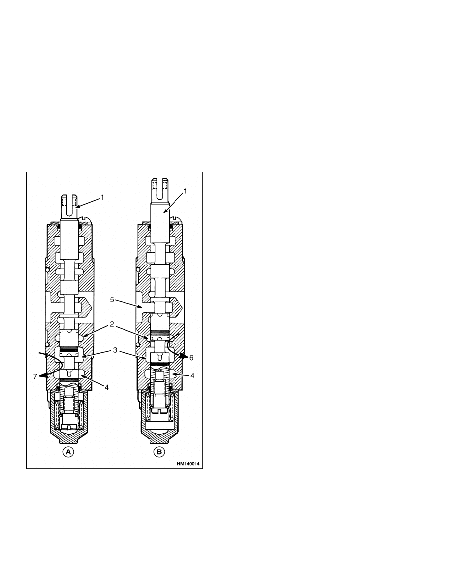
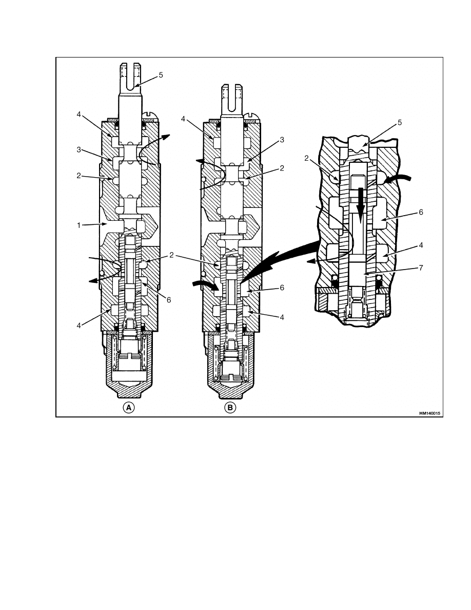
TILT SECTION
The basic operation of the tilt spool is the same as
the other spools in this control valve. The tilt control
spool that is inside the tilt spool adds an additional
sequence to the tilt forward function.
Tilt Backward
When the spool is moved to the Back Tilt position, the
tilt spool causes a restriction of the oil flow through
the open center passage. See Figure 4. The increased
pressure in the parallel passage causes the oil to flow
through the check valve to the supply cavity. The oil
flows from the supply cavity through a section of the
spool to the rod side of the tilt cylinders. The check
valve prevents the movement of the load until the
system pressure is great enough to control the load.
Oil from the piston end of the tilt cylinders returns
through the main control valve to the hydraulic tank.
Tilt Forward
The tilt control spool that is inside of the tilt spool
operates during the Forward Tilt function. See Fig-
ure 4. The tilt control spool prevents cavitation in
the piston end of the tilt cylinders. Cavitation occurs
when the available fluid does not fill the space in a
closed system. The high vacuum causes some of the
fluid to change to bubbles of gas. When cavitation
occurs in the tilt cylinders, the tilt forward function
is not smooth.
The tilt control spool permits the regulation of the
tilt speed by using the pressure from the hydraulic
pump.
The pressure must be 550 kPa (80 psi) on the piston
end of the tilt cylinders. The tilt control spool pre-
vents oil flow from the rod end of the tilt cylinders
until the pressure is 550 kPa (80 psi). This action
makes sure that a vacuum cannot occur at the piston
end of the tilt cylinders.
4
2000 SRM 1085
Operation
A. TILT BACKWARD
B. TILT FORWARD
1.
OPEN CENTER PASSAGE
2.
SUPPLY CAVITY
3.
TO/FROM PISTON END OF TILT CYLINDERS
4.
DRAIN CAVITY
5.
TILT SPOOL
6.
TO/FROM ROD END OF TILT CYLINDERS
7.
TILT CONTROL SPOOL
Figure 4. Tilt Spool Operation
5
Operation
2000 SRM 1085
RELIEF VALVE
The relief valves control the maximum pressure
within a hydraulic circuit. The control valve has a
primary relief valve and a secondary relief valve.
The primary relief valve is installed in the inlet
section of the control valve and is for the lift and tilt
circuits. The secondary relief valve is for the auxil-
iary circuits and is installed in the outlet section of
the control valve. Both relief valves are the same
in description and operation. When the pressure in
one of the hydraulic circuits reaches the relief valve
setting, the relief valve opens a path between the
inlet and drain circuits.
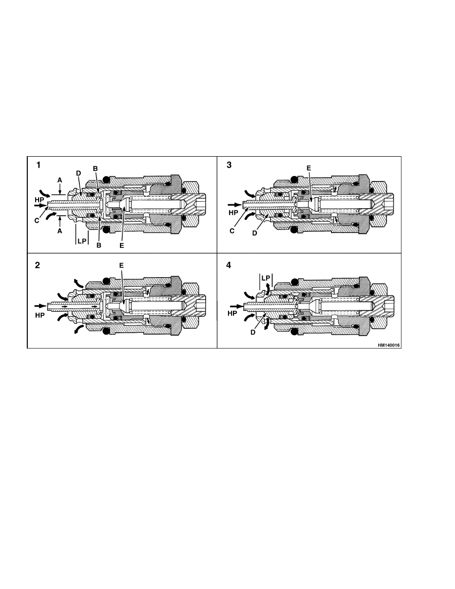
The relief valve is a poppet valve that is pilot op-
erated. There are four poppet spools in this valve.
Spools C, D, and E are used for pressure relief. This
relief valve gives almost constant relief pressure over
the range of the hydraulic pump flow. The sequence
of operation is described in Figure 5.
1.
STEP 1 - THE RELIEF VALVE IS CLOSED BETWEEN THE HIGH PRESSURE (HP) INLET AND THE LOW
PRESSURE (LP) DRAIN. HIGH PRESSURE OIL ENTERS THE PASSAGE AT C. THE DIFFERENCE IN
AREA BETWEEN DIAMETERS A AND B HOLDS THE POPPET SPOOL D AGAINST THE VALVE SEAT.
2.
STEP 2 - THE OIL PRESSURE IN THE HIGH PRESSURE INLET BECOMES GREATER THAN THE SPRING
FORCE OF THE PILOT POPPET E. THE PILOT POPPET E IS PUSHED FROM ITS SEAT. OIL FLOWS
AROUND THE POPPET E AND THROUGH THE PASSAGES TO THE DRAIN.
3.
STEP 3 - WHEN PILOT POPPET E OPENS, THE LOSS OF OIL PRESSURE BEHIND POPPET C CAUSES
POPPET C TO MOVE AGAINST POPPET E. THIS MOVEMENT STOPS THE FLOW OF OIL THROUGH C
AND CAUSES A LOWER PRESSURE BEHIND RELIEF VALVE POPPET D.
4.
STEP 4 - THE DIFFERENCE IN PRESSURE ON EACH SIDE OF POPPET D CAUSES POPPET D TO OPEN.
THE HIGH PRESSURE OIL THEN HAS A DIRECT PATH TO THE LOW PRESSURE DRAIN.
Figure 5. Relief Valve Operation
6
2000 SRM 1085
Main Control Valve Repair
Main Control Valve Repair
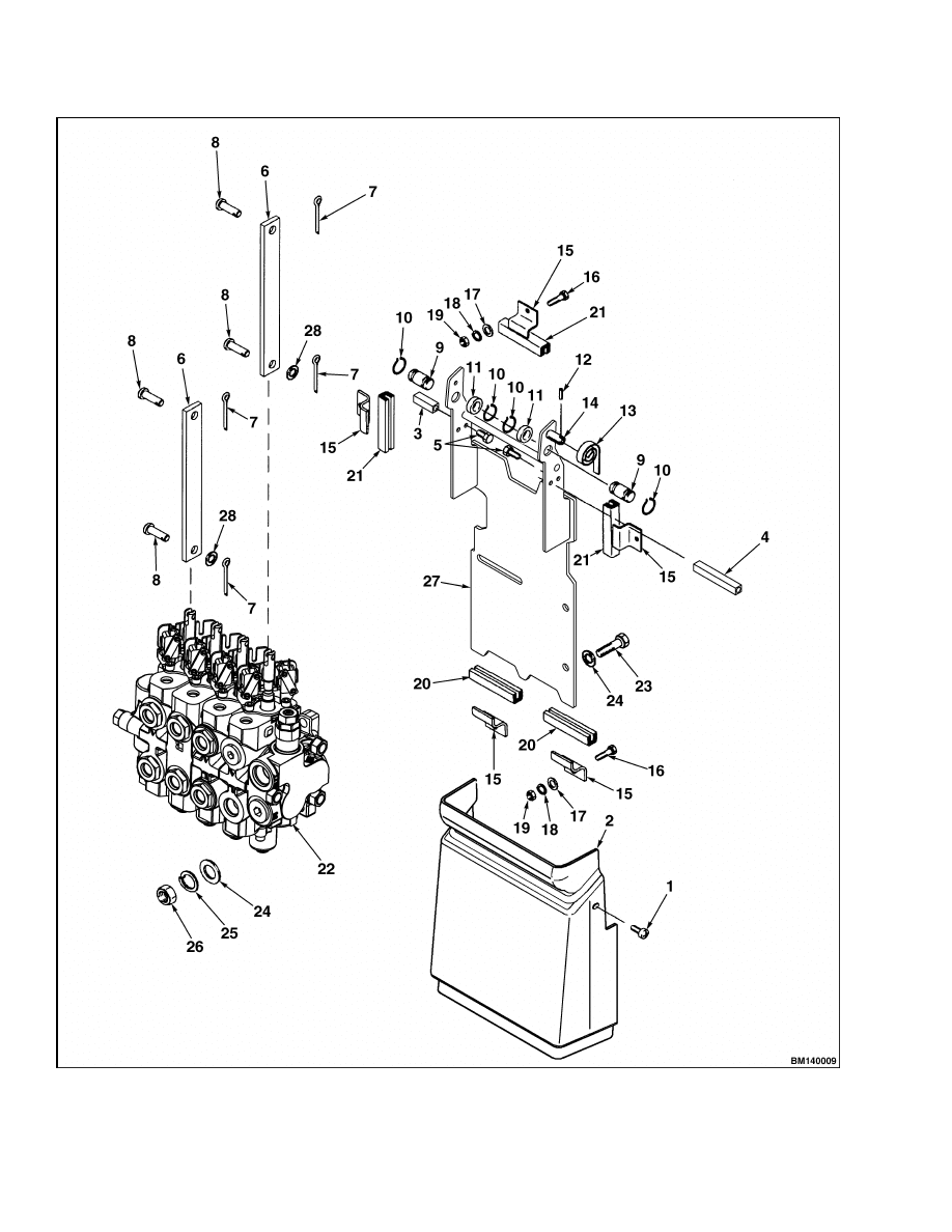
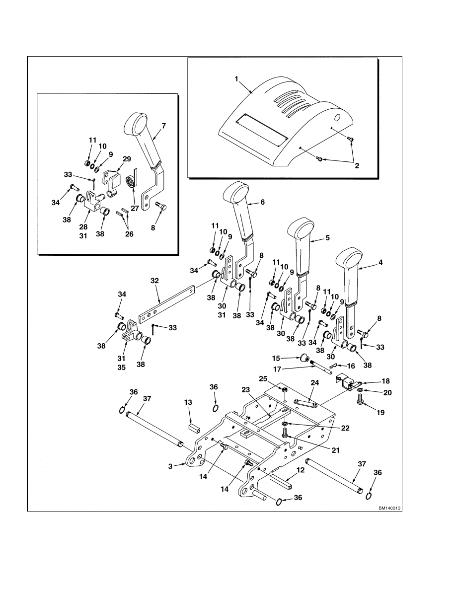
REMOVE
The hydraulic control valve assembly is mounted to
a supporting bracket, which is secured to the frame
of the truck. To remove these parts, use the following
procedures and see Figure 6.
WARNING
Before making any repairs to the control valve,
tilt the forks until they are parallel to the floor.
Lower the mast until the forks rest on the floor.
This action will prevent the mast from lower-
ing suddenly when the hydraulic lines are dis-
connected.
1.
Fully lower the mast.
2.
Disconnect the battery. Remove the battery to
gain access to the mounting capscrews for the
hydraulic control valve. Follow the instructions
in Periodic Maintenance 8000 SRM 1079 for
battery removal information.
3.
Remove the battery spacer plates, if required.
WARNING
Hydraulic oil is hot at normal operating tem-
perature.
CAUTION
Disposal of lubricants and fluids must meet lo-
cal environmental regulations.
4.
Operate the control valve levers in both direc-
tions to relieve any hydraulic pressure.
5.
Remove the screws (1) securing the lower cover.
Remove the cover.
NOTE:
Install plugs and caps to the hydraulic hoses
and fittings to prevent leaking and to prevent dirt
from entering the system.
6.
Tag and disconnect the pressure and supply
line from the pump. This line can be accessed
through the battery compartment.
7.
Tag and disconnect all remaining hydraulic hoses
at the fittings. Drain any excess hydraulic oil
into a suitable container.
8.
Disconnect the hydraulic wiring harness connec-
tor from the main wiring harness.
WARNING
The hydraulic control valve is heavy. Be sure
that all lifting devices (hoists, cables, chains,
slings, etc.) are suitable and of adequate capac-
ity to lift the hydraulic control valve. The hy-
draulic control valve can weigh 11.4 to 13.6 kg
(25 to 30 lb) without any attachments.
9.
Support the hydraulic control valve assembly.
Remove the three capscrews (16), washers (17),
lockwashers (18), nuts (19), and brackets (15)
securing the top of the supporting bracket to the
frame. Loosen the two capscrews (16), washers
(17), lockwashers (18), nuts (19), and brack-
ets (15) securing the bottom of the supporting
bracket to the frame. Carefully lift the entire
hydraulic control valve assembly and supporting
bracket out of the truck.
10. Move the hydraulic control valve assembly and
supporting bracket to a clean workbench.
11. Remove the cotter pins (7), washers (28), if appli-
cable, and pins (8) connecting the lower linkage
to the hydraulic control valve.
12. Remove the three mounting capscrews (23),
washers (24), lockwashers (25), and nuts (26)
securing the hydraulic control valve to the sup-
porting bracket. Remove the hydraulic control
valve from the supporting bracket.
7
Main Control Valve Repair
2000 SRM 1085
Figure 6. Main Control Unit Mounting
8
2000 SRM 1085
Main Control Valve Repair
Legend for Figure 6
1.
SCREW
2.
LOWER COVER
3.
STANDOFF
4.
STANDOFF
5.
CAPSCREW
6.
LINK
7.
COTTER PIN
8.
PIN
9.
PIN
10. SNAP RING
11. SPACER
12. PIN
13. SPRING
14. STUD
15. BRACKET
16. CAPSCREW
17. WASHER
18. LOCKWASHER
19. NUT
20. LOWER RUBBER CHANNEL
21. UPPER RUBBER CHANNEL
22. CONTROL VALVE
23. CAPSCREW
24. WASHER
25. LOCKWASHER
26. NUT
27. SUPPORT BRACKET
28. WASHER
NOTE: Refer to Figure 7 for upper linkage and con-
trol lever assembly.
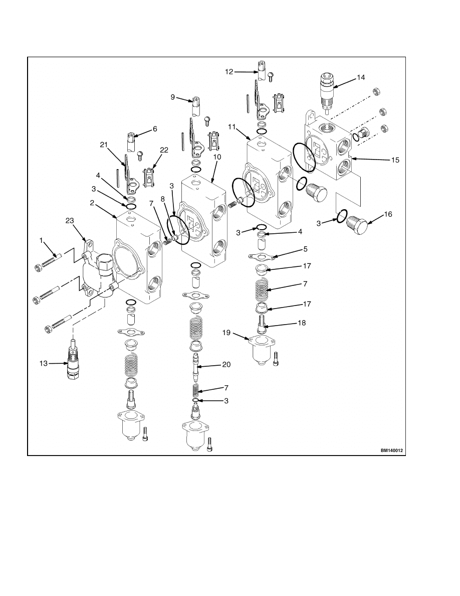
DISASSEMBLE
1.
Clean the exterior of the hydraulic control valve.
NOTE:
Disassemble the main control valve as nec-
essary for repairs. Most repairs to the main control
valve are for the replacement of O-rings and seals to
stop leaks. The passages in the tilt spool are small
and may need cleaning if the hydraulic oil becomes
dirty. The section normally must be replaced, if the
spool or valve section is damaged.
2.
Remove the end cap from the valve section. See
Figure 8. Carefully pull the spool from the valve
section. Do not remove the spring retainers, un-
less a spring must be replaced.
3.
Tag and disconnect all electrical connections
from the valve switches.
4.
The valve sections can be separated when the
three through-bolts are removed.
The check
valves are held in the valve body by the next
section.
5.
Remove the tilt control spool by removing the end
of the tilt spool. Carefully remove the tilt control
spool from the tilt spool.
CLEAN AND INSPECT
WARNING
Cleaning solvents can be flammable and toxic
and can cause skin irritation.
When using
cleaning solvents, always follow the solvent
manufacturer’s recommended safety proce-
dures.
1.
Clean only the parts of the control valve with
solvent.
Do not get solvent in the electrical
switches.
2.
Check the spools and bores for wear or damage.
If a spool or the bores have damage, the control
valve section must be replaced. Make sure the
spools move freely in the bores.
3.
Check the check valves and relief valve(s) for
damage. Replace the parts as necessary.
4.
The relief valve is normally replaced as an as-
sembly if it is damaged.
5.
Check the parts of the linkage for the control
valve levers. Replace worn parts as necessary.
ASSEMBLE
CAUTION
Before installing the parts into the valve body,
make sure all parts are clean. Replace all the
seals and the O-rings. Lubricate the moving
parts with clean hydraulic oil during assembly.
1.
Install new seals in the bores of the sections. See
Figure 8. Install new O-ring seals between the
sections. Install the check valves and springs
and assemble the sections.
Tighten the nuts
on the small through-bolts to 10 N•m (7 lbf ft).
Tighten the nuts on the large through-bolt to
24 N•m (18 lbf ft).
9
Main Control Valve Repair
2000 SRM 1085
Figure 7. Main Control Valve Upper Lever Mounting
10
2000 SRM 1085
Main Control Valve Repair
Legend for Figure 7
1.
UPPER COVER
2.
SCREW
3.
LINKAGE FRAME
4.
LIFT HAND LEVER
5.
TILT HAND LEVER
6.
3RD FUNCTION HAND LEVER
7.
4TH FUNCTION HAND LEVER
8.
CAPSCREW
9.
WASHER
10. LOCKWASHER
11. NUT
12. STANDOFF
13. STANDOFF
14. CAPSCREW
15. KNOB
16. PIN
17. LATCH ROD
18. LATCH
19. CAPSCREW
20. WASHER
21. CAPSCREW
22. WASHER
23. LOCKOUT STRAP
24. NUT PLATE
25. NUT
26. PIN
27. SPRING
28. PIVOT
29. CRANK
30. CRANK
31. SPACER (NOT SHOWN)
32. LINK
33. COTTER PIN
34. PIN
35. ROCKER ARM
36. SNAP RING
37. PIVOT PIN
38. FLANGE BEARING
2.
If the return springs were removed from the con-
trol spools, install the spring retainers. During
assembly, use new O-rings for the parts of the tilt
control spool. Do not damage the O-rings during
installation.
3.
Lubricate the spools with clean hydraulic oil. En-
sure spool is free of contamination. Carefully in-
stall the spools in the valve body. Install the seal
retainers and the covers for the return springs.
4.
Install the relief valves. Adjust the relief settings
for the hydraulic system as described in Pressure
Relief Valve Check and Adjustment.
5.
Connect all electrical connections to the valve
switches.
INSTALL
The hydraulic control valve assembly is mounted to
a supporting bracket, which is secured to the frame
of the truck. To install these parts, use the following
procedures and see Figure 6.
WARNING
The hydraulic control valve is heavy. Be sure
that all lifting devices (hoists, cables, chains,
slings, etc.) are suitable and of adequate capac-
ity to lift the hydraulic control valve. The hy-
draulic control valve can weigh 11.4 to 13.6 kg
(25 to 30 lb) without any attachments.
1.
Align and secure the hydraulic control valve to
the supporting bracket by installing the three
mounting capscrews (23), washers (24), lock-
washers (25), and nuts (26).
2.
Install the pins (8), washers (28), if applicable,
and cotter pins (7) connecting the lower linkage
to the hydraulic control valve.
3.
Ensure that the three upper rubber channels (21)
are properly installed on the supporting bracket.
While supporting the hydraulic control valve as-
sembly, carefully position the supporting bracket
in the lower rubber channels (20) and tighten
the two capscrews (16), washers (17), lockwash-
ers (18), nuts (19), and brackets (15) securing the
bottom of the supporting bracket to the frame.
4.
Install the three brackets (15), capscrews (16),
washers (17), lockwashers (18), and nuts (19) se-
curing the top of the supporting bracket to the
frame.
5.
Connect the hydraulic wiring harness connector
to the main wiring harness.
11
Main Control Valve Repair
2000 SRM 1085
1.
THROUGH-BOLT
2.
AUXILIARY SECTION
3.
O-RING
4.
SEAL
5.
RETAINER
6.
AUXILIARY SPOOL
7.
SPRING
8.
CHECK VALVE
9.
TILT SPOOL
10. TILT SECTION
11. LIFT/LOWER SECTION
12. LIFT/LOWER SPOOL
13. SECONDARY RELIEF VALVE
14. PRIMARY RELIEF VALVE
15. INLET SECTION
16. PLUG
17. SPRING CUP
18. SCREW
19. END CAP
20. TILT CONTROL SPOOL
21. BRACKET
22. SWITCH
23. OUTLET SECTION
Figure 8. Main Control Valve
12
2000 SRM 1085
Main Control Valve Repair
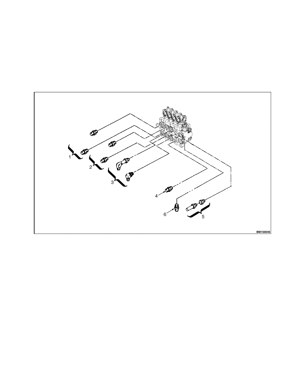
6.
Remove caps and plugs from the hydraulic hoses
and fittings. Connect the pressure and supply
line to the pump.
Connect all remaining hy-
draulic hoses at the fittings. See Figure 9.
7.
Check the level of hydraulic oil in the tank. If
necessary, add hydraulic oil.
8.
Install the battery. Follow the instructions in Pe-
riodic Maintenance 8000 SRM 1079 for bat-
tery installation information. Connect the bat-
tery connector.
9.
Operate the lift, tilt, and auxiliary controls.
Check for leaks from the hydraulic hoses and
valve connections.
10. Install the lower cover.
1.
AUXILIARY 2
2.
AUXILIARY 1
3.
TILT
4.
LIFT
5.
TO FILTER
6.
FEED FROM PUMP
Figure 9. Hydraulic Line Arrangement
13
Pressure Relief Valve Check and Adjustment
2000 SRM 1085
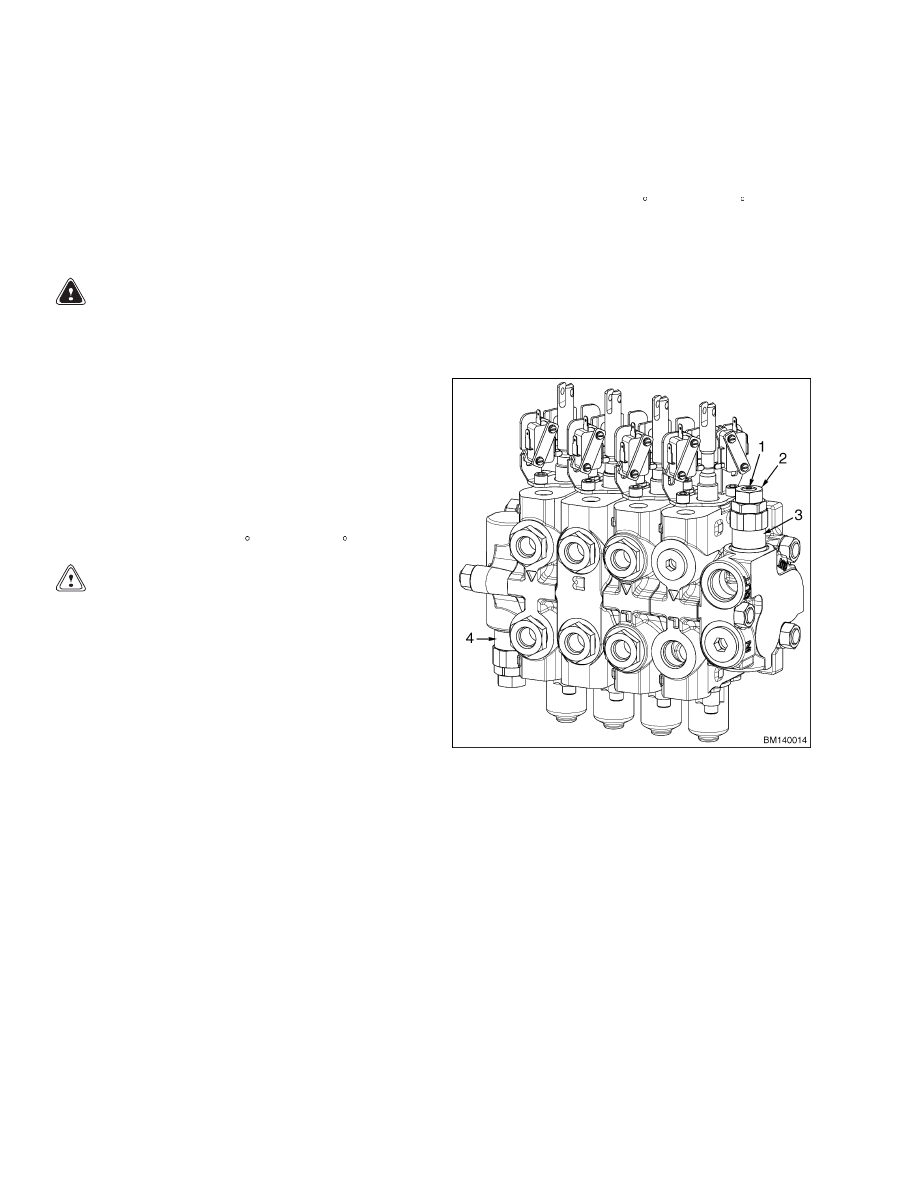
Pressure Relief Valve Check and Adjustment
NOTE: The main control valve has two relief valves:
a primary relief valve and a secondary relief valve.
The primary relief valve is in the inlet section of the
control valve. The secondary relief valve is in the
outlet section of the control valve. See Figure 10.
PRIMARY RELIEF VALVE
WARNING
Never allow anyone under a raised carriage.
Do not put any part of your body in or through
the lift mechanism unless all parts of the mast
are completely lowered and the key switch is
OFF.
1.
Insert a tee fitting into the pressure supply line
to the mast. Connect a 25 MPa (3600 psi) gauge
to the tee fitting.
2.
Loosen the jam nut.
3.
Operate the hydraulic system to warm the oil
temperature to 55 to 65 C (131 to 149 F).
CAUTION
During this test, the mast must be fully ex-
tended. Make sure there is enough overhead
clearance in the building, or do the test out-
doors.
4.
Raise the mast until it stops. Hold the lever and
check the reading of the gauge when the relief
valve opens. Turn the adjustment screw, as nec-
essary, to change the setting. The correct setting
is 17.9 MPa (2600 psi). Tighten the jam nut when
the adjustment is correct.
5.
Remove the gauge when the checks are complete.
SECONDARY RELIEF VALVE
1.
Insert a tee fitting into the tilt or auxiliary cir-
cuit. Connect a 20 MPa (3000 psi) gauge to the
tee fitting.
2.
Loosen the jam nut on the relief valve.
3.
Operate the hydraulic system to warm the oil
temperature to 55 to 65 C (131 to 149 F).
4.
Tilt the mast backward until it stops. Hold the
lever and check the reading of the gauge when
the relief valve opens.
Turn the adjustment
screw, as necessary, to change the setting. The
correct setting is 13.8 MPa (2000 psi). Tighten
the jam nut when the adjustment is correct.
5.
Remove the gauge when the checks are complete.
1.
ADJUSTMENT SCREW
2.
JAM NUT
3.
PRIMARY RELIEF VALVE
4.
SECONDARY RELIEF VALVE
Figure 10. Relief Valve Locations
14

2000 SRM 1085
Troubleshooting
Troubleshooting
PROBLEM
POSSIBLE CAUSE
PROCEDURE OR ACTION
Slow or no movement of
cylinders.
Air is in the hydraulic system.
Remove air from hydraulic system.
The hydraulic pump is worn or dam-
aged.
Repair or replace hydraulic pump.
Restriction in the hydraulic lines.
Repair hydraulic lines.
Cylinder seals are damaged.
Repair cylinders.
Load is greater than capacity.
Reduce load.
Linkage is disconnected or damaged.
Repair and adjust linkage for control
levers.
Pressure relief valve(s) is not ad-
justed correctly or is damaged.
Repair or adjust relief valve(s).
Large leaks between spool and bore.
Replace valve section.
Switch plates are not installed or ad-
justed correctly.
Check position of switch plates.
Pump motor fails to turn on.
Failed control valve switch.
Replace switch.
Open circuit.
Check wiring connections.
Check
wiring continuity.
Switch plates are not installed or ad-
justed correctly.
Check position of switch plates.
Oil leaks at the end of a
spool.
Seal for spool is damaged.
Replace seal.
Spool is damaged.
Replace valve section.
Valve body is damaged.
Replace valve section.
Hydraulic pressure is above
specifications.
Pressure relief valve(s) is not ad-
justed correctly or is damaged.
Repair or adjust relief valve(s).
Restriction in return line.
Clean or replace return line or filter.
15

Troubleshooting
2000 SRM 1085
PROBLEM
POSSIBLE CAUSE
PROCEDURE OR ACTION
Tilt cylinders extend when
the tilt spool is in the NEU-
TRAL position.
Cylinder seal has leaks.
Repair tilt cylinders.
Oil leaks between control valve spool
and bore.
Replace valve section.
Hydraulic lines have leaks.
Repair or tighten lines or fittings.
Tilt cylinders extend sud-
denly when the tilt spool is
moved to BACK TILT posi-
tion.
Check valve for tilt spool is damaged.
Replace check valve.
Tilt cylinders extend sud-
denly when the tilt spool is
moved to FORWARD TILT
position.
Tilt control spool inside the tilt spool
is damaged.
Replace valve section.
Lift cylinders retract when
the lift spool is in the NEU-
TRAL position.
Check valve for the lift spool is dam-
aged.
Replace check valve.
Cylinder seals have leaks.
Repair lift cylinders.
Hydraulic lines have leaks.
Repair or tighten lines or fittings.
Leaks between the lift spool and the
bore.
Replace valve section.
Spool will not move or is dif-
ficult to move.
Linkage is disconnected or damaged.
Repair and adjust linkage.
Return spring is damaged.
Replace spring.
The spool or bore is damaged.
Replace valve section.
Spool will not return to
NEUTRAL.
Linkage is disconnected or damaged.
Repair and adjust linkage.
Return spring is damaged.
Replace spring.
Dirt between spool and the bore.
Clean valve.
Spool is bent or damaged.
Replace valve section.
16


TECHNICAL PUBLICATIONS
2000 SRM 1085
3/04 Printed in United Kingdom
Document Outline
- toc
Wyszukiwarka
Podobne podstrony:
1554632 2000SRM1086 (06 2004) UK EN
1554635 8000SRM1079 (06 2004) UK EN
1554636 8000SRM1080 (11 2004) UK EN
1554629 1800SRM1076 (03 2004) UK EN
1564053 0600SRM1101 (03 2004) UK EN
899782 2000SRM0077 (03 2005) UK EN
1554628 1600SRM1075 (03 2004) UK EN
1554630 1900SRM1077 (06 2004) UK EN
1565181 2000SRM1108 (08 2004) UK EN
1554635 8000SRM1079 (06 2004) UK EN
więcej podobnych podstron