PERIODIC
MAINTENANCE
J1.6-2.0XMT (J30-40ZT) [J160]
PART NO. 1554635
8000 SRM 1079

SAFETY PRECAUTIONS
MAINTENANCE AND REPAIR
• When lifting parts or assemblies, make sure all slings, chains, or cables are correctly
fastened, and that the load being lifted is balanced. Make sure the crane, cables, and
chains have the capacity to support the weight of the load.
• Do not lift heavy parts by hand, use a lifting mechanism.
• Wear safety glasses.
• DISCONNECT THE BATTERY CONNECTOR before doing any maintenance or repair
on electric lift trucks. Disconnect the battery ground cable on internal combustion lift
trucks.
• Always use correct blocks to prevent the unit from rolling or falling. See HOW TO PUT
THE LIFT TRUCK ON BLOCKS in the Operating Manual or the Periodic Mainte-
nance section.
• Keep the unit clean and the working area clean and orderly.
• Use the correct tools for the job.
• Keep the tools clean and in good condition.
• Always use HYSTER APPROVED parts when making repairs. Replacement parts
must meet or exceed the specifications of the original equipment manufacturer.
• Make sure all nuts, bolts, snap rings, and other fastening devices are removed before
using force to remove parts.
• Always fasten a DO NOT OPERATE tag to the controls of the unit when making repairs,
or if the unit needs repairs.
• Be sure to follow the WARNING and CAUTION notes in the instructions.
• Gasoline, Liquid Petroleum Gas (LPG), Compressed Natural Gas (CNG), and Diesel fuel
are flammable. Be sure to follow the necessary safety precautions when handling these
fuels and when working on these fuel systems.
• Batteries generate flammable gas when they are being charged. Keep fire and sparks
away from the area. Make sure the area is well ventilated.
NOTE: The following symbols and words indicate safety information in this
manual:
WARNING
Indicates a condition that can cause immediate death or injury!
CAUTION
Indicates a condition that can cause property damage!

Periodic Maintenance
Table of Contents
TABLE OF CONTENTS
Introduction........................................................................................................................................................
General ...........................................................................................................................................................
Discharging the Capacitors...........................................................................................................................
How to Move Disabled Lift Truck .................................................................................................................
How to Tow Lift Truck...............................................................................................................................
How to Put Lift Truck on Blocks...................................................................................................................
How to Raise Drive Tires ..........................................................................................................................
How to Raise Steer Tires...........................................................................................................................
Safety Procedures When Working Near Mast..................................................................................................
Maintenance Schedule.......................................................................................................................................
Maintenance Procedures Every 8 Hours or Daily............................................................................................
Checks With the Key Switch OFF ................................................................................................................
Safety Labels and Decals ..........................................................................................................................
Frame .........................................................................................................................................................
Wheels and Tires .......................................................................................................................................
Mast, Carriage, and Forks ........................................................................................................................
Hydraulic Oil Level and Leaks.................................................................................................................
Operator and Battery Restraints .............................................................................................................
Battery Check............................................................................................................................................
Checks With the Key Switch ON ..................................................................................................................
Electrical Components ..............................................................................................................................
Directional Speed Control.........................................................................................................................
Steering System ........................................................................................................................................
Hydraulic System ......................................................................................................................................
Brakes ........................................................................................................................................................
Maintenance Procedures Every 500 Hours or 3 Months .................................................................................
Tire and Wheel Assemblies ...........................................................................................................................
Mast and Carriage.........................................................................................................................................
Battery ...........................................................................................................................................................
Parking Brakes ..............................................................................................................................................
Transaxle........................................................................................................................................................
Maintenance Procedures Every 1000 Hours or 6 Months ...............................................................................
Lift Chains .....................................................................................................................................................
Hydraulic Breather Cap ................................................................................................................................
Master Cylinder .............................................................................................................................................
Electrical Inspection ......................................................................................................................................
Hydraulic Motor Brushes..........................................................................................................................
Contactors..................................................................................................................................................
Directional Speed Control.........................................................................................................................
Transaxle, Oil Change ...................................................................................................................................
Maintenance Procedures Every 2000 Hours or Yearly ....................................................................................
Steering ..........................................................................................................................................................
Hydraulic........................................................................................................................................................
Hydraulic Oil Filter, Change ....................................................................................................................
Hydraulic Oil Strainer, Check ..................................................................................................................
Hydraulic Oil, Change ..............................................................................................................................
General Repairs .................................................................................................................................................
Welding Repairs.............................................................................................................................................
Painting Instructions ....................................................................................................................................
Lift and Tilt System Leak Check ......................................................................................................................
Lift System.....................................................................................................................................................
©2004 HYSTER COMPANY
i

Table of Contents
Periodic Maintenance
TABLE OF CONTENTS (Continued)
Tilt System .....................................................................................................................................................
Battery Maintenance .........................................................................................................................................
How to Charge Battery..................................................................................................................................
How to Change Battery .................................................................................................................................
Battery Size Specifications............................................................................................................................
This section is for the following models:
J1.6-2.0XMT (J30-40ZT) [J160]
ii
8000 SRM 1079
Introduction
Introduction
GENERAL
This section contains the instructions for periodic
maintenance and inspection and a maintenance
schedule.
The maintenance schedule has time intervals for in-
spection, lubrication, and periodic maintenance. The
time intervals are based on normal operation. Nor-
mal operation is considered to be one 8-hour shift per
day in a relatively clean environment on an improved
surface. Multiple shifts or dirty operating conditions
will reduce the recommended time intervals between
services.
WARNING
Do not make repairs or adjustments unless you
are properly trained and have authorization to
do so. Repairs and adjustments that are not
correct can create dangerous operating condi-
tions. Do not operate a lift truck that needs re-
pairs. Report the need for repairs to your su-
pervisor immediately. If repair is necessary, at-
tach a DO NOT OPERATE tag to the steering
wheel and remove the key.
Some users have service personnel and facilities to
perform the procedures listed in the maintenance
schedule. Service manuals are available from your
local dealer to help users who perform their own
repairs.
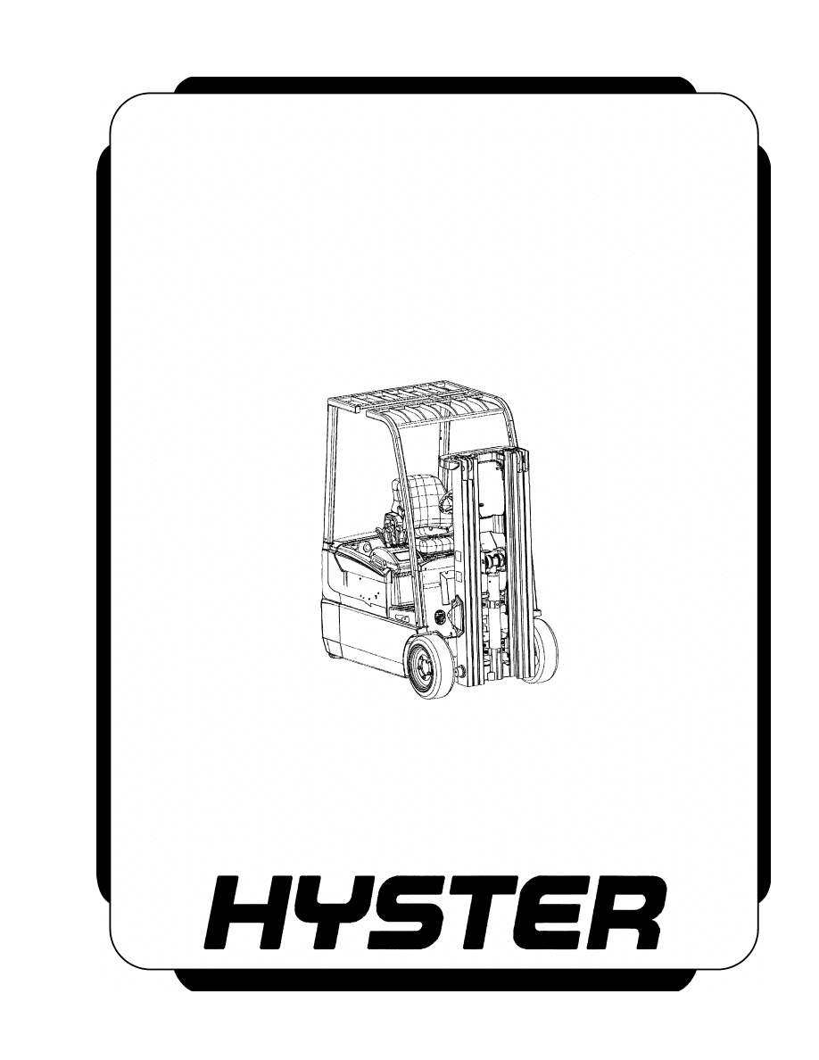
A. LEFT SIDE
B. RIGHT SIDE
C. FORWARD
TRAVEL
Figure 1. Truck Orientation
Your local dealer has the trained personnel and
equipment to conduct a complete program of inspec-
tion, lubrication, and maintenance. This program
will help your truck operate at its peak performance
and increase the life span of its components.
Throughout this section, forward will refer to travel
in the direction of the forks and left and right will be
determined by sitting in the seat facing forward. See
Figure 1.
DISCHARGING THE CAPACITORS
WARNING
Do not make repairs or adjustments unless you
are properly trained and have authorization to
do so. Repairs and adjustments that are not
correct can create dangerous operating condi-
tions. Do not operate a lift truck that needs re-
pairs. Report the need for repairs to your su-
pervisor immediately. If repair is necessary, at-
tach a DO NOT OPERATE tag to the steering
wheel and remove the key.
WARNING
Disconnect the battery before opening the elec-
trical compartment cover or inspecting or re-
pairing the electrical system. If a tool causes
a short circuit, the high current flow from the
battery can cause personal injury or property
damage.
WARNING
Some checks and adjustments are performed
with the battery connected. Do not connect the
battery until the procedure tells you to do so.
Never have any metal on your fingers, arms,
or neck. Metal items can accidentally make an
electrical connection and cause injury.
WARNING
Block the lift truck drive tires to prevent unex-
pected movement before performing any tests
or adjustments.
1
Introduction
8000 SRM 1079
WARNING
The capacitor in the transistor controller can
hold an electrical charge after the battery is
disconnected. To prevent an electrical shock
and personal injury, discharge the capacitor
before inspecting or repairing any component
in the electrical compartment.
Wear safety
glasses.
Make certain that the battery has
been disconnected.
CAUTION
To avoid controller damage, always discon-
nect the battery and discharge the capacitor.
NEVER put power to the controller while any
power wires are disconnected. NEVER short
any controller terminal or motor terminal to
the battery. Make sure to use proper proce-
dure when servicing the controller.
1.
Block load wheels to prevent lift truck from mov-
ing.
2.
Turn key switch to OFF position and disconnect
the battery.
3.
Open the electrical compartment:
a. Remove two screws securing the electrical
compartment door.
b. Pull the compartment door open on its
hinges.
WARNING
DO NOT short across the motor controller ter-
minals with a screwdriver or jumper wire.
NOTE: Some lift trucks are equipped with a premium
controller, which controls the hydraulic motor as well
as the traction motors.
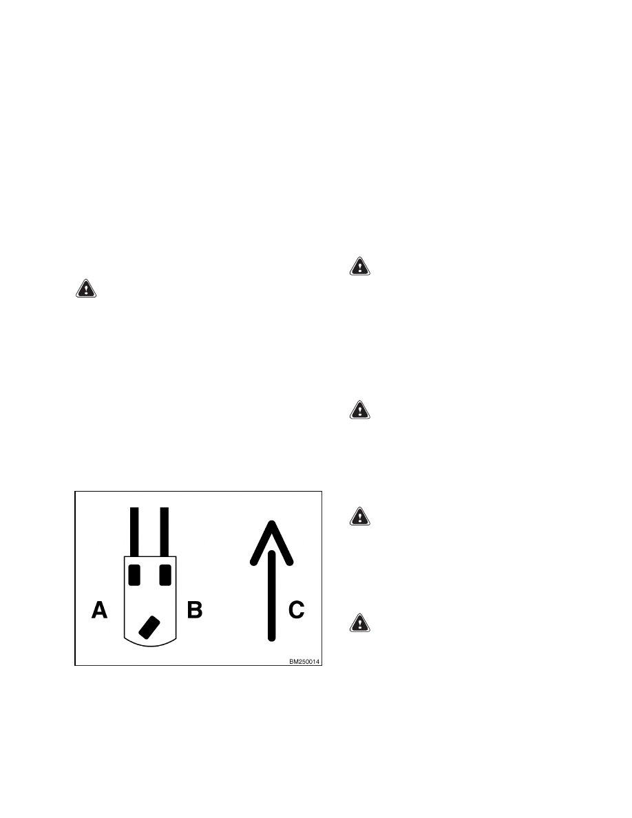
4.
Discharge the capacitor in the controller by con-
necting a 200-ohm, 2-watt resistor across the
controller’s BT+ and B
terminals for 10 seconds
using insulated jumper wires. See Figure 2.
5.
On the premium controller, also connect the 200-
ohm, 2-watt resistor across the controller’s P+
and B
terminals for 10 seconds using insulated
jumper wires. See Figure 3.
6.
Remove the 200-ohm, 2-watt resistor before re-
connecting the battery.
1.
POSITIVE CONNECTION (BT+)
2.
NEGATIVE CONNECTION (B )
3.
INSULATED JUMPER WIRES
4.
200-OHM, 2-WATT RESISTOR
Figure 2. Discharging the Capacitors
(Standard)
1.
POSITIVE CONNECTION (BT+)
2.
NEGATIVE CONNECTION (B )
3.
INSULATED JUMPER WIRES
4.
200-OHM, 2-WATT RESISTOR
5.
POSITIVE CONNECTION (P+)
Figure 3. Discharging the Capacitors
(Premium)
2
8000 SRM 1079
Introduction
HOW TO MOVE DISABLED LIFT TRUCK
How to Tow Lift Truck
WARNING
Use extra caution when moving a lift truck dur-
ing the following conditions:
• Brakes do not operate correctly.
• Steering does not operate correctly.
• Tires are damaged.
• Traction conditions are bad.
• Moving the lift truck on a steep grade.
If the steering pump motor does not operate,
steering control of the lift truck can be slow.
This can make the control of the lift truck dif-
ficult. If there is no electrical power, steering
can be difficult. Do not tow the lift truck if
there is no power. Poor traction can cause the
disabled lift truck or towing vehicle to slide.
Steep grades will require additional brake
force to stop the lift truck.
Never carry a disabled lift truck unless the lift
truck MUST be moved and cannot be towed.
The lift truck used to carry the disabled lift
truck MUST have a rated capacity equal to
or greater than the weight of the disabled
lift truck.
The capacity must be for a load
center equal to half the width of the disabled
lift truck. See the nameplate of the disabled
lift truck for the approximate total weight.
The forks must extend the full width of the
disabled lift truck. Center the weight of the
disabled lift truck on the forks and be careful
not to damage the under side of the lift truck.
NOTE: The towed lift truck must have an operator
and an adequately charged battery to energize the
parking brake coils. Tow the lift truck slowly.
1.
Raise the carriage and forks approximately
30 cm (12 in.) from the surface. Install a chain
to prevent the carriage and mast channels from
moving.
2.
If another lift truck is used to tow the disabled lift
truck, it must have a weight equal to or greater
than that of the disabled lift truck. Install an ap-
proximate half-capacity load on the forks of the
lift truck that is being used to tow the disabled
lift truck. This half-capacity load will increase
the traction of the towing lift truck. Keep the
load as low as possible.
3.
Turn the key switch to the OFF position and dis-
connect the battery by pressing the emergency
disconnect switch to the STOP position.
4.
Position blocks in front of and behind the drive
tires to prevent unexpected movement.
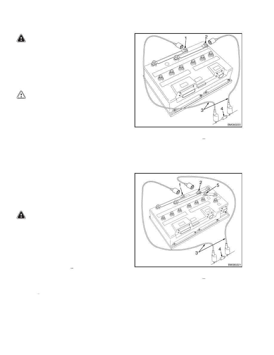
5.
Locate the parking brake connectors (BRK_RUN
1, BRK_RUN 2, and the BRK_TOWING) beside
the brake diode on the main wiring harness.
These items are found near the front, right
wheel well. See Figure 4.
1.
BRK_RUN 1
2.
BRK_RUN 2
3.
BRK_TOWING
4.
BRAKE DIODE
5.
MAIN WIRING
HARNESS
Figure 4. Brake Diode and Release Connectors
6.
If a charged battery is not installed in the lift
truck, use special tool - Auxiliary Battery Con-
nector (Hyster™ P/N 1564329) and an auxiliary
24-volt power supply to energize the brake over-
ride circuit:
a. Disconnect the BRK_RUN 1 and BRK_RUN
2 connectors.
b. Connect the auxiliary battery connector to
the BRK_RUN 2 connector.
c.
Connect the jumper wires to the 24-volt aux-
iliary power source and listen for the parking
brakes to release.
7.
If a charged battery is installed in the lift truck,
use the BRK_TOWING connector to energize the
brake override circuit:
a. Disconnect the BRK_RUN 1 and BRK_RUN
2 connectors.
b. Connect the BRK_TOWING and BRK_RUN
2 connectors.
3
Introduction
8000 SRM 1079
c.
Pull the emergency disconnect switch to the
RUN position and listen for the parking
brakes to release.
8.
Use a towing link made of steel that attaches to
the tow pins in the counterweights of both lift
trucks.
NOTE: Tow slowly and listen for sounds other than
normal. If the parking brakes do not release or there
are other signs of damage (noises), stop towing and
repair on site or carry the lift truck using a larger
lift truck if necessary. When repairs are complete,
return the brake connectors to operation mode and
test for proper operation before returning to service.
HOW TO PUT LIFT TRUCK ON BLOCKS
How to Raise Drive Tires
WARNING
The lift truck must be put on blocks for some
types of maintenance and repair. The removal
of the following assemblies will cause large
changes in the center of gravity: mast and
load axle, battery, and counterweight.
Put
the lift truck on blocks only if the surface is
solid, even, and level.
Make sure that any
blocks used to support the lift truck are solid,
one-piece hardwood blocks. Put blocks in front
and back of the tires to prevent unexpected
movement of the lift truck.
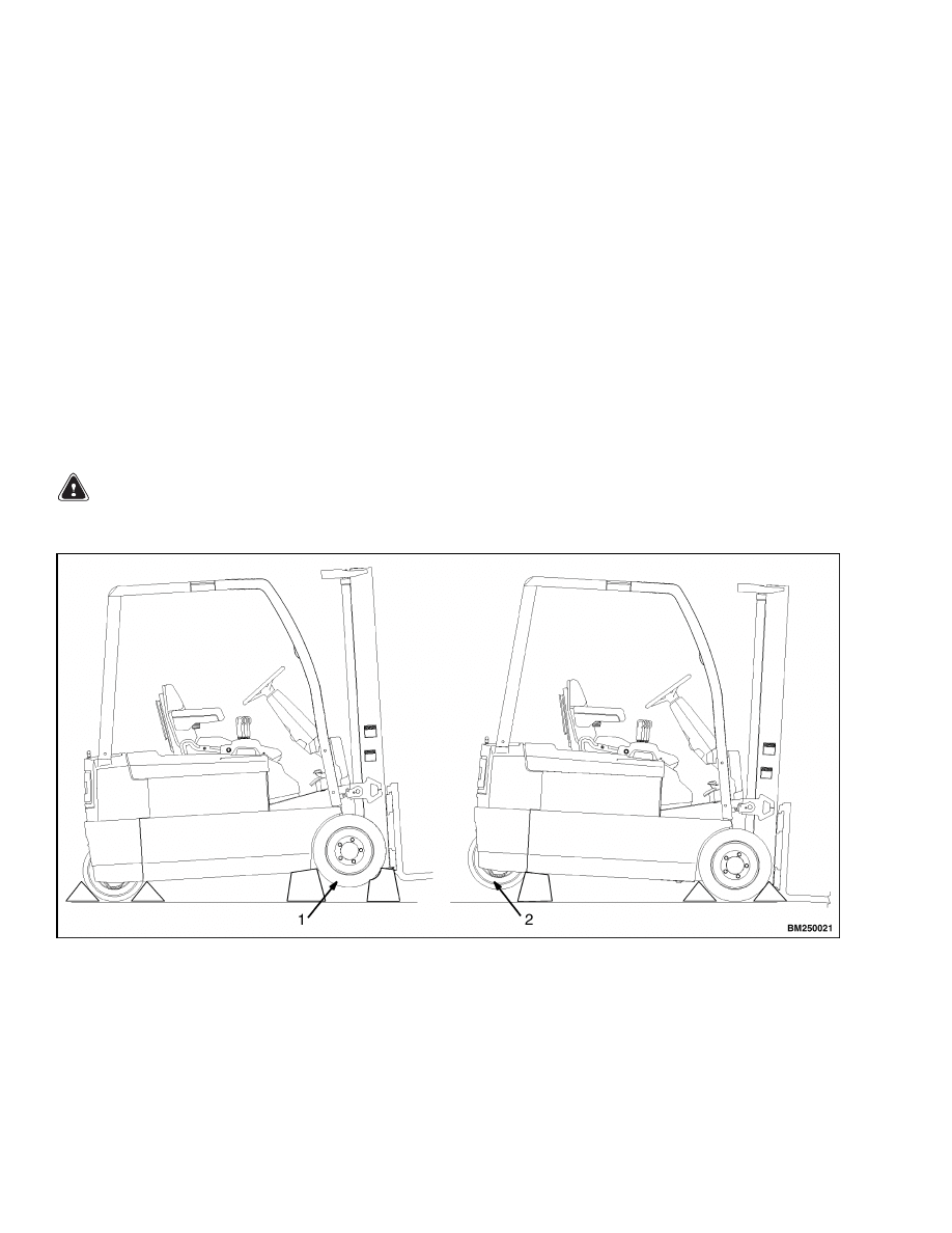
1.
Block the steer tires to prevent movement of the
lift truck. See Figure 5.
2.
Use a hydraulic jack under each side of the frame
near the front. Make sure each jack has a ca-
pacity equal to at least half the weight of the lift
truck. See the nameplate for weight specifica-
tions.
3.
Put a block under each outer mast channel.
4.
Put additional blocks under the frame behind the
drive tires.
1.
DRIVE TIRES
2.
STEER TIRES
Figure 5. Putting Lift Truck on Blocks
4

8000 SRM 1079
Safety Procedures When Working Near Mast
How to Raise Steer Tires
WARNING
The lift truck must be put on blocks for some
types of maintenance and repair. The removal
of the following assemblies will cause large
changes in the center of gravity:
mast and
load axle, battery, and counterweight.
Put
the lift truck on blocks only if the surface is
solid, even, and level.
Make sure that any
blocks used to support the lift truck are solid,
one-piece hardwood blocks. Put blocks in front
and back of the tires to prevent movement of
the lift truck.
NOTE: The counterweight has lifting eyes, on which
the overhead guard is mounted. When the overhead
guard is removed, these lift points can be used to
raise the steer tire so blocks can be positioned un-
der the frame.
1.
Put blocks in front and back of the drive tires to
prevent movement of the lift truck. See Figure 5.
2.
Use hydraulic jacks to raise the steer tire. Posi-
tion a jack under each side of the frame near the
counterweight to raise the lift truck. DO NOT
place jacks under the counterweight. Make sure
that the jacks have a total capacity of at least 2/3
of the total weight of the lift truck as shown on
the nameplate.
3.
Place blocks under the frame to support the lift
truck. DO NOT place blocks under the counter-
weight.
Safety Procedures When Working Near Mast
The following procedures must be used when inspect-
ing or working near the mast. Additional precautions
and procedures may be required when repairing or
removing the mast.
WARNING
Mast parts are heavy and can shift. Distances
between parts are small.
Serious injury or
death can result if part of the body is hit by
parts of the mast or the carriage.
• Never put any part of the body into or under
the mast or carriage unless all parts are com-
pletely lowered or a safety chain is PROP-
ERLY INSTALLED. Also, make sure that the
key switch is in the OFF position and the bat-
tery connector is disconnected. Attach a DO
NOT OPERATE tag to the steering wheel.
• Be careful of the forks.
When the mast is
raised, the forks can be at a height to cause
an injury.
• DO NOT climb on the mast or lift truck at any
time. Use a ladder or personnel lift to work
on the mast.
• DO NOT use blocks to support the mast weld-
ments or to restrain their movement.
• Mast repairs require disassembly and re-
moval of parts and may require removal of
the mast or carriage. Follow the repair pro-
cedures in the proper section for each mast.
WHEN WORKING NEAR THE MAST, ALWAYS:
1.
Lower the mast and carriage completely. Push
the lift/lower control lever forward and make
sure there is no movement in the mast. Make
sure that all parts of the mast that move are
fully lowered.
OR
2.
If parts of the mast must be in raised position,
install a safety chain to restrain the moving parts
of the mast. Connect moving parts to a part that
does not move. Follow these procedures:
a. Put the mast in a vertical position.
b. Raise the mast to align the bottom cross-
member of the weldment that moves in the
outer weldment with a crossmember on the
outer weldment. On the two-stage mast, the
moving part is the inner weldment. On the
three-stage mast, it is the intermediate weld-
ment. On the four-stage mast, it is the first
intermediate weldment. See Figure 6.
c.
Use a 9.4 mm (0.370 in.) minimum safety
chain with a hook to fasten the crossmem-
bers together so the movable member cannot
lower. Put the hook on the back side of the
mast. Make sure the hook is completely en-
gaged with a link in the chain. Make sure
the safety chain does not touch lift chains or
chain sheaves, tubes, hoses, fittings, or other
parts on the mast.
5
Safety Procedures When Working Near Mast
8000 SRM 1079
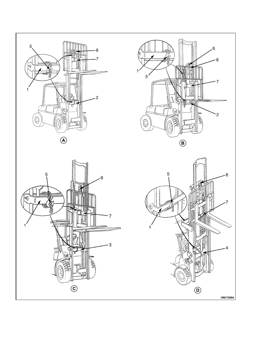
Figure 6. Safety Chaining the Mast
6
8000 SRM 1079
Maintenance Schedule
Legend for Figure 6
A. TWO-STAGE MAST
B. FREE-LIFT MAST
C. THREE-STAGE MAST
D. FOUR-STAGE MAST
1.
OUTER WELDMENT
2.
INNER WELDMENT
3.
INTERMEDIATE WELDMENT
4.
FIRST INTERMEDIATE WELDMENT
5.
HOOK
6.
FREE-LIFT CYLINDER
7.
CROSSMEMBER
8.
CROSSMEMBER
d. Install
another
safety
chain
[9.4
mm
(0.370 in.)
minimum] between the top or
bottom crossmember of the carriage and a
crossmember on the outer weldment.
e.
Lower the mast until there is tension in the
safety chain(s) and the free-lift cylinder (free-
lift masts only) is completely retracted.
3.
Turn the key switch to the OFF position and
disconnect the battery. Attach a DO NOT RE-
MOVE tag from the safety chain(s).
Maintenance Schedule
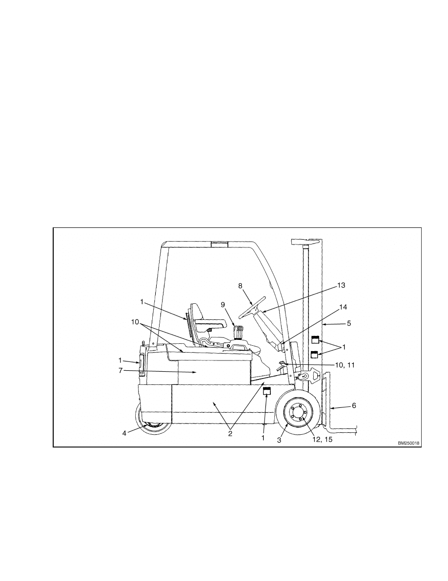
Figure 7. Maintenance Points
7

Maintenance Schedule
8000 SRM 1079
Table 1. Maintenance Schedule
Item
No.
Item
8 hr
or
1 day
3
500 hr
or
3
months
3
1000 hr
or
6
months
3
2000 hr
or
1 year
3
Procedure or
Quantity
Specification
1
Safety Labels and
Operating Manual
X
Replace if
Necessary
See Parts Manual
2
Frame, Covers, and
Floor Plates
X
Visually Inspect
for Damage
Repair as Required
Drive Tire and
Wheel Assemblies
Tire and Wheel
X
Check Condition Remove Foreign
Objects Embedded
in Tire
3
Lug Bolt Torque
X
7
Tighten if
Required
170 N•m (125 lbf ft)
Steering Tire and
Wheel Assemblies
Tire and Wheel
X
Check Condition Remove Foreign
Objects Embedded
in Tire
4
Lug Nut Torque
X
7
Tighten if
Required
170 N•m (125 lbf ft)
X = Check C = Change L = Lubricate
1
Equalization Charge approximately each month but not more than each week
2
Multipurpose Grease with 2-4% Molybdenum Disulfide for normal operations
3
Whichever comes first
4
Low temperature hydraulic oil where applicable (HCE-79)
5
Service after initial 50 hrs and at the recommended intervals thereafter
6
Service after initial 200 hrs and at the recommended intervals thereafter
7
When installing, check after every 2-5 hrs until nuts stay tight for an 8-hr shift. Check every 500 hrs
or 3 months thereafter.
NOTE: Never use steam to clean electrical parts.
8

8000 SRM 1079
Maintenance Schedule
Table 1. Maintenance Schedule (Continued)
Item
No.
Item
8 hr
or
1 day
3
500 hr
or
3
months
3
1000 hr
or
6
months
3
2000 hr
or
1 year
3
Procedure or
Quantity
Specification
Mast
X
Inspect for
Visible Damage
Check Operation
Pivots, Sliding
Surfaces
L
As Required
Multipurpose Grease
2
Trunnion
Capscrews
X
Tighten if
Required
35 N•m (26 lbf ft)
Trunnion Bush
L
2 Lube Fittings
Multipurpose Grease
2
X
Inspect for
Visible Damage
Replace if Necessary
X
Check Stretch
Replace if Necessary
5
Lift Chains
L
Lubricate as
Required
SAE 20 or 30
Engine Oil
Carriage Assembly
X
Inspect for
Visible Damage
Check Operation
Forks
X
Check for
Damage
Replace if Necessary
X
Check Operation Repair as Required
Fork Guides and
Locks
L
Lubricate as
Required
Silicone Spray
Lubricant
6
Sideshift
Wear
Bearings
X
Check/Replace
Four Places
2.38 mm (0.09 in.)
Minimum Thickness
X
Check Level
Distilled Water
7
Battery
X
1
Equalization
Charge
X = Check C = Change L = Lubricate
1
Equalization Charge approximately each month but not more than each week
2
Multipurpose Grease with 2-4% Molybdenum Disulfide for normal operations
3
Whichever comes first
4
Low temperature hydraulic oil where applicable (HCE-79)
5
Service after initial 50 hrs and at the recommended intervals thereafter
6
Service after initial 200 hrs and at the recommended intervals thereafter
7
When installing, check after every 2-5 hrs until nuts stay tight for an 8-hr shift. Check every 500 hrs
or 3 months thereafter.
NOTE: Never use steam to clean electrical parts.
9

Maintenance Schedule
8000 SRM 1079
Table 1. Maintenance Schedule (Continued)
Item
No.
Item
8 hr
or
1 day
3
500 hr
or
3
months
3
1000 hr
or
6
months
3
2000 hr
or
1 year
3
Procedure or
Quantity
Specification
X
Check Operation
Steering System
X
Check for Leaks
8
Steering Actuator
Capscrews
X
Tighten if
Required
290 N•m (215 lbf ft)
Hydraulic System
X
X
Check Operation
Check for Leaks
Repair as Required
Hydraulic Oil
X
C
17.8 liter (4.7 gal) Hydraulic Oil - ISO
VG 46 (HCE-140)
Filter
C
5
Change Filter
See Parts Manual
Breather Cap
X
Clean or Replace See Parts Manual
Hydraulic Motor
Brushes
X
Check Condition 1.5 mm (.060 in.) From
Holder (Min.)
9
Hydraulic Oil
Strainer
C
Clean or Replace See Parts Manual
X
Check Operation Repair as Required
10
Pedals, Seat
Assembly, Hood,
Hinges, and Hood
latch
L
As Required
Silicone Spray
Lubricant
X
Check Operation Hydraulic Oil - ISO
VG 46 (HCE-140)
4
11
Service Brake
X
Check for Leaks
X = Check C = Change L = Lubricate
1
Equalization Charge approximately each month but not more than each week
2
Multipurpose Grease with 2-4% Molybdenum Disulfide for normal operations
3
Whichever comes first
4
Low temperature hydraulic oil where applicable (HCE-79)
5
Service after initial 50 hrs and at the recommended intervals thereafter
6
Service after initial 200 hrs and at the recommended intervals thereafter
7
When installing, check after every 2-5 hrs until nuts stay tight for an 8-hr shift. Check every 500 hrs
or 3 months thereafter.
NOTE: Never use steam to clean electrical parts.
10

8000 SRM 1079
Maintenance Schedule
Table 1. Maintenance Schedule (Continued)
Item
No.
Item
8 hr
or
1 day
3
500 hr
or
3
months
3
1000 hr
or
6
months
3
2000 hr
or
1 year
3
Procedure or
Quantity
Specification
X
Check Operation
Parking Brake
X
Check Hold on
Grade
15% Grade (Max Load)
12
Air Gap
X
Measure Air Gap 0.30-0.46 mm
(0.012-0.018 in.)
13
Directional/Speed
Control
X
L
Check Operation Silicone Spray
Lubricant
Electrical Circuits
Horn, Lights, and
Alarms
X
Check Operation Repair as Required
Display Panel
X
Check Operation Troubleshoot
Electrical System
14
Contactors
X
Check Condition Repair as Required
15
Transaxle
Oil Level
X
6
C
6
0.35 liter
(0.37 qt) Each
Hydraulic Oil
JDM J20
(HCE 102)
Breather
X
Clean and Check
Operation
X = Check C = Change L = Lubricate
1
Equalization Charge approximately each month but not more than each week
2
Multipurpose Grease with 2-4% Molybdenum Disulfide for normal operations
3
Whichever comes first
4
Low temperature hydraulic oil where applicable (HCE-79)
5
Service after initial 50 hrs and at the recommended intervals thereafter
6
Service after initial 200 hrs and at the recommended intervals thereafter
7
When installing, check after every 2-5 hrs until nuts stay tight for an 8-hr shift. Check every 500 hrs
or 3 months thereafter.
NOTE: Never use steam to clean electrical parts.
11

Maintenance Procedures Every 8 Hours or Daily
8000 SRM 1079
Maintenance Procedures Every 8 Hours or Daily
CHECKS WITH THE KEY SWITCH OFF
WARNING
The capacitor in the transistor controller can
hold an electrical charge after the battery is
disconnected. To prevent electrical shock and
injury, discharge the capacitor before inspect-
ing or repairing any component in the electri-
cal compartment. Wear safety glasses. Make
certain the battery has been disconnected.
Park the lift truck on a level surface. Lower the forks,
turn the key switch to the OFF position, and discon-
nect the battery connector. Check for leaks and con-
ditions that are not normal. Clean up any oil spills.
NOTE: Be certain to read and understand the infor-
mation covered in the introduction section before per-
forming any of the maintenance procedures listed be-
low.
Make the following checks:
• Condition of the safety labels and decals
• Condition of the frame, including the overhead
guard and counterweight
• Condition of the wheels and tires
• Condition of the mast, including the carriage and
forks
• Hydraulic oil level and fluid leaks
• Operation of safety components, including the seat,
seat belt, battery restraint, and latch
• Electrolyte level and correct battery size and
weight for the lift truck
Safety Labels and Decals
WARNING
If labels that have warnings or instructions are
damaged, they must be replaced immediately.
Safety labels are installed on the lift truck to give
information about possible hazards. Check that all
safety labels are installed in the correct locations on
the lift truck. Make sure that no labels are damaged
and that all labels can be read. See Frame 100 SRM
1073 for information on replacing labels and decals.
Frame
The frame is a single weldment with mounts for the
counterweight, overhead guard, mast, steering sys-
tem, hydraulic system, and transaxles. Check the
condition of the frame, especially around welds, for
rust, cracks, or other damage. The overhead guard
must be free from defects to ensure protection to the
operator. A variety of covers and floor plates provide
protection and allow easy access to systems located
inside and around the frame. Make certain that all
covers and floor plates are present and secured in
their proper locations.
Wheels and Tires
WARNING
When installing the wheels, check all wheel
nuts after 2 to 5 hours of operation. Tighten
the nuts in a cross pattern to the correct torque
value. When the nuts stay tight after an 8-hour
check, the interval for checking the torque can
be extended to 500 hours or 3 months.
Inspect the drive tires and wheel assemblies and the
steer tire and wheel assemblies for damage. Look
for deep grooves or cuts in the tires. Remove objects
embedded in the tire, such as wire, rocks, glass, and
pieces of metal that can cause damage. Remove any
wire, strapping, or other material that is wrapped
around the axle to prevent damage to the transaxle
seals. Inspect wheel rims for rust or cracks and check
for loose or missing lug nuts and broken studs. DO
NOT operate a lift truck with damage to any wheel
rim, lug nuts, or studs.
Mast, Carriage, and Forks
WARNING
Special precautions are required when work-
ing on or near the mast or carriage. See Safety
Procedures When Working Near Mast.
1.
Inspect the welds on the mast and carriage for
cracks. Make sure that the capscrews and nuts
are tight.
2.
Inspect the channels for wear in the areas where
the rollers travel. Check the rollers for wear or
damage.
3.
Inspect the load backrest extension for cracks
and damage.
4.
Lubricate the lift chains with SAE 20 or 30 en-
gine oil if necessary.
Lubrication of chains is
12
8000 SRM 1079
Maintenance Procedures Every 8 Hours or Daily
regularly performed at the 500-hr/3-month inter-
val but may be lubricated earlier if needed.
5.
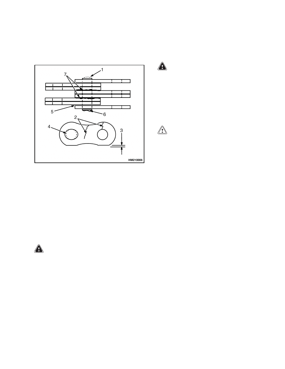
Inspect the lift chains for cracks or broken links
and pins. See Figure 8.
1.
WARPED PIN
2.
CRACKS
3.
EDGE WEAR
4.
HOLE WEAR
5.
LOOSE LEAVES
6.
DAMAGED PIN
7.
CORROSION
Figure 8. Lift Chains Check
6.
Inspect the chain anchors and pins for cracks and
damage.
7.
Make sure the lift chains are adjusted so they
have equal tension. Adjustment or replacement
of lift chains must be performed by properly
trained, authorized service personnel.
WARNING
Never repair damaged forks by heating or
welding.
Forks are made of tempered steel
using special procedures.
Replace damaged
forks.
8.
Inspect the forks for cracks and wear.
Check
the alignment of the fork tips. The difference in
height of the fork tips must be less than three
percent of the length of the forks. Some applica-
tions may require closer alignment. If the forks
do not meet specification, they must be replaced.
Check that the bottom of each fork is not exces-
sively worn. Check for smooth and proper oper-
ation of the fork lock pins. Repair or replace any
damaged or broken fork lock pins or components
and lubricate as necessary.
Hydraulic Oil Level and Leaks
WARNING
The hydraulic oil is HOT at normal operat-
ing temperature and can cause severe burns.
Avoid contact between hot oil and unprotected
skin.
Hydraulic oil under pressure can be injected
into the skin. Never check for leaks by putting
hands on hydraulic lines or components under
pressure.
CAUTION
Protect the hydraulic system from dirt and
contaminants when servicing the hydraulic
system.
Never operate the pump without the proper
amount of oil in the hydraulic system.
The
operation of the hydraulic pump with low oil
levels will damage the pump.
The hydraulic, steering, and brake systems use
hydraulic oil to operate. The hydraulic and steering
systems draw oil from the hydraulic tank, circu-
late it through their systems, and return it into
the hydraulic tank.
The brake system also uses
hydraulic oil but is a self-contained system.
An
indicator light notifies the operator when the brake
system hydraulic oil level is too low. The hydraulic
oil for the brake system is contained in the master
cylinder reservoir. Check for leaks by looking for
oil under the lift truck and where the lift truck has
been parked. Remove the floor mat and floor plates
to inspect the brake lines, master cylinder, steering
pump, hydraulic tank, hydraulic pump, and hoses.
Oil leaks may appear as wet, oily leaks or unusually
dirty areas where dirt and dust sticks to oil that has
slowly leaked out.
Check the hydraulic oil level when the carriage is
lowered and the key switch is in the OFF position.
Remove the breather cap/dipstick from the top of the
hydraulic tank. Wipe the dipstick clean and rein-
stall the breather cap/dipstick into the tank. Remove
again and check the oil level. Add hydraulic oil only
as needed. If more hydraulic oil is added than the
FULL level, hydraulic oil will leak from the breather
during operation.
13
Maintenance Procedures Every 8 Hours or Daily
8000 SRM 1079
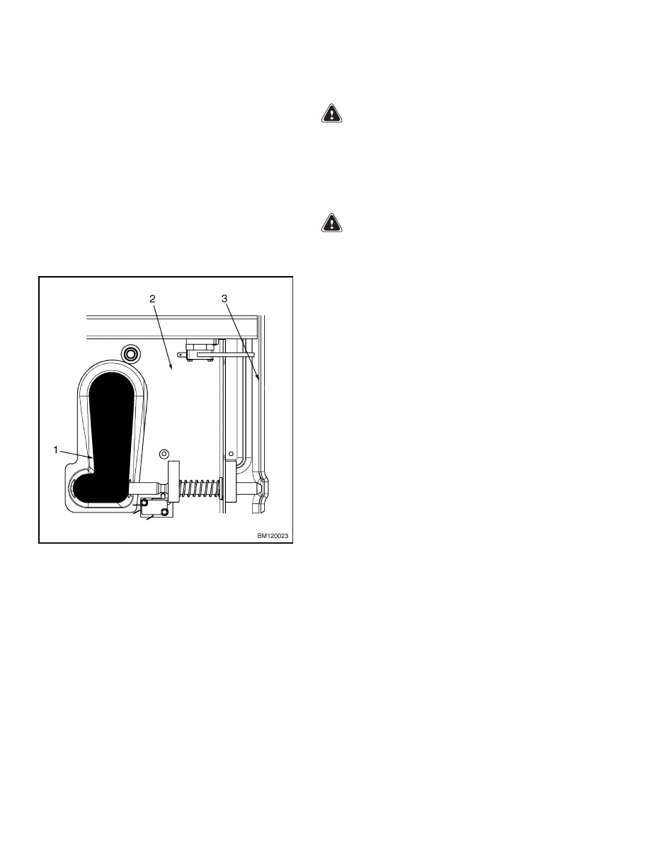
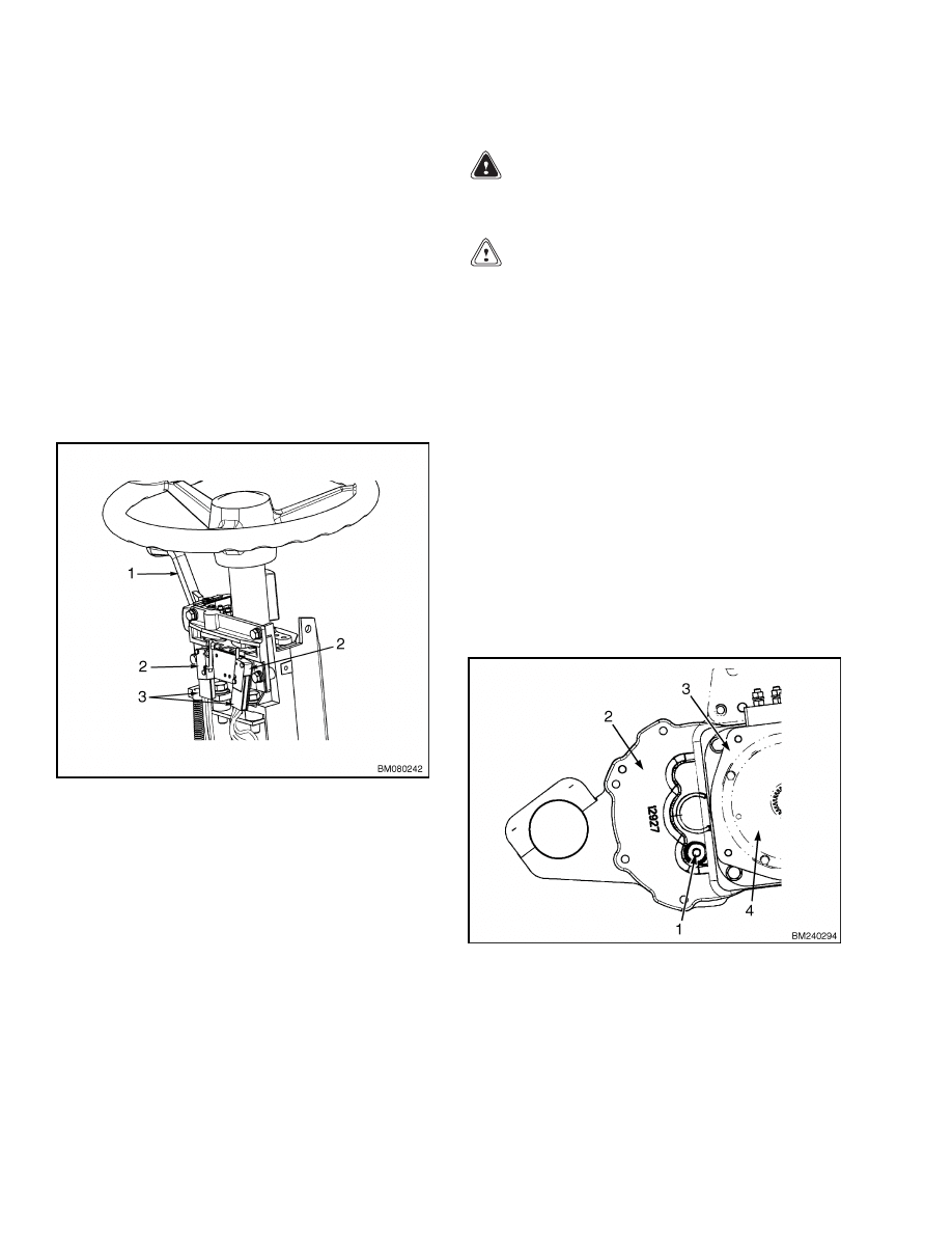
Operator and Battery Restraints
The hood functions as a battery restraint to hold the
battery in the battery compartment if an accident
causes the lift truck to tip over. Two hinges at the
back of the hood attach it to the frame. A sliding latch
mechanism on the front of the hood locks it closed
during operation. See Figure 9. The latch can be ac-
cessed by releasing and raising the hydraulic levers
and linkage assembly up and out of the way. The
latch must be in good condition and properly secured
before the lift truck can be operated. If the latch does
not lock the hood in the closed position, the hydraulic
levers and linkage assembly will not lock into posi-
tion and the lift truck will not operate.
1.
SLIDING LATCH MECHANISM
2.
HOOD
3.
FRAME
Figure 9. Latch Mechanism
The hood, seat belt, hip restraint brackets, seat, and
seat mounts are all parts of the operator restraint
system. Check that the seat and mounts are securely
mounted to the hood. The adjustment functions of
the seat should release and move smoothly, and en-
gage securely. Check the seat belt for cuts or frays
and make certain that it buckles securely and re-
leases smoothly.
Battery Check
WARNING
Make sure the key switch is in the OFF position
and the directional lever is in the NEUTRAL
position before connecting the battery. If the
lift truck was operated with a discharged bat-
tery, check all contactors for welded tips BE-
FORE a charged battery is connected.
WARNING
Do not put tools on the battery. Metallic ob-
ject on the battery can cause a short circuit and
possible damage or injury.
The acid in the electrolyte can cause injury.
If the electrolyte is spilled, use water to flush
the area. Make the acid neutral with a solu-
tion of sodium bicarbonate (baking soda). Ar-
eas where acid has contacted the skin should
be flushed with water immediately. Acid in the
eyes must be flushed with water continuously
for 10 minutes; then seek medical attention.
Batteries generate explosive fumes. Keep the
vents in the caps clean. Keep sparks or open
flames away from the battery area. Be care-
ful not to make sparks when disconnecting the
battery connections.
Disconnect the battery
when performing maintenance.
The battery must fit the battery compartment
so the battery restraint will operate correctly.
Use spacers to prevent the battery from moving
more than 13 mm (0.5 in.) in any direction.
Make sure the battery weight ranges between the
maximum and minimum weight shown on the Name-
plate. Check that the battery is charged and has the
correct voltage and ampere-hour rating for the lift
truck as shown on the Nameplate. Keep the battery
case, top cover, and the area for the battery clean and
painted. Leakage and corrosion from the battery can
cause a malfunction in the electric controls of the lift
truck. Use a water and sodium bicarbonate solution
(baking soda) to clean the battery and the battery
area. Keep the top of the battery clean, dry, and free
of corrosion. Inspect the battery case, connector, and
cables for damage, cracks, or breaks. See your local
battery dealer to repair any damage.
14

8000 SRM 1079
Maintenance Procedures Every 8 Hours or Daily
Check the level of the electrolyte daily on a minimum
of one cell. Choose a cell at random. The electrolyte
level should be halfway between the top of the plates
and the bottom of the fill hole. Add only distilled
water. If the level in the cell checked is low, check
all the cells and add distilled water as needed.
CHECKS WITH THE KEY SWITCH ON
After completing the Checks With the Key Switch
OFF, perform the Checks With the Key Switch ON
before placing the lift truck into service.
Electrical Components
Turning the key switch to the ON position energizes
the electrical systems of the lift truck. The horn, ac-
tivated by a switch located in the steering wheel cap,
must operate to ensure safe operations by alerting
persons nearby that you are operating the lift truck
in their immediate area. Lift trucks may be equipped
with backup alarms and visual alerts such as a strobe
light. Check that all lighting and alarms are operat-
ing properly before placing the lift truck into service.
The display panel, located on the dash at the front of
the operator’s compartment, is also energized when
the key switch is turned to the ON position. The dis-
play is essential to safe and productive operation of
the lift truck. Systems such as the battery condition
and fault codes are monitored by the controller and
are expressed by the display. A malfunctioning dis-
play unit may not alert an operator to a condition in
time to prevent damage to system components on the
lift truck.
Directional Speed Control
On standard models, a directional control lever is lo-
cated on the steering column. Turn the key switch to
the ON position; place the directional control lever
in the forward position. Gently press the accelerator
pedal on the right hand floor of the operator’s com-
partment. The truck should begin to smoothly move
forward. Stop the truck, place the directional control
lever in the reverse position, and gently press the ac-
celerator. The truck should now move in reverse.
Premium models control the direction of travel and
acceleration with the MONOTROL™ foot pedal.
This two-function pedal controls forward direction
and speed by pressing on the left side of the pedal.
Reverse is controlled by depressing the right hand
side of the pedal. The amount of pressure on either
side of the pedal determines the acceleration rate.
Steering System
The steering system should operate when a properly
charged battery is connected, an operator is present
in the seat, and the key switch is in the ON position.
Move the steering tire and wheel assembly com-
pletely to the left by turning the steering wheel. The
assembly should turn smoothly to its stop. The steer-
ing tire should stop approximately parallel to the
battery. Turn the steering tire and wheel assembly
completely to its right hand stop using the steering
wheel. The steering system should move smoothly
and make a full range of motion from its full left to
full right position (approximately 180 degrees).
Hydraulic System
WARNING
The hydraulic oil is HOT at normal operat-
ing temperature and can cause severe burns.
Avoid contact between hot oil and unprotected
skin.
Hydraulic oil under pressure can be injected
into the skin. Never check for leaks by putting
hands on hydraulic lines or components under
pressure.
CAUTION
Protect the hydraulic system from dirt and
contaminants when the oil level is checked or
the filter is changed.
Never operate the pump without the proper
amount of oil in the hydraulic system.
The
operation of the hydraulic pump with low oil
levels will damage the pump.
Check the hydraulic system by sitting in the seat to
close the seat switch and turning the key switch to
the ON position. Raise and lower the mast repeat-
edly. The mast should move smoothly and should not
bounce or jerk when stopping or starting. Check each
function of the control valve for proper operation.
15
Maintenance Procedures Every 500 Hours or 3 Months
8000 SRM 1079
Brakes
Check the service brakes for proper operation by
slowly moving the lift truck in a safe direction and
apply the service brake by pressing the brake pedal.
The lift truck should stop quickly. If the lift truck
does not stop properly or if the brake pedal feels soft
or spongy, troubleshoot the service brake system.
The parking brakes are engaged at all times when
the truck is stopped. Turning the key switch to the
OFF position or pressing the emergency disconnect
button on the hood will also cause the parking brakes
to immediately apply. Move the lift truck slowly in a
safe direction and listen for signs the parking brakes
are dragging. Allow the truck to stop and listen for
the "click" of the parking brakes properly engaging.
Maintenance Procedures Every 500 Hours or 3 Months
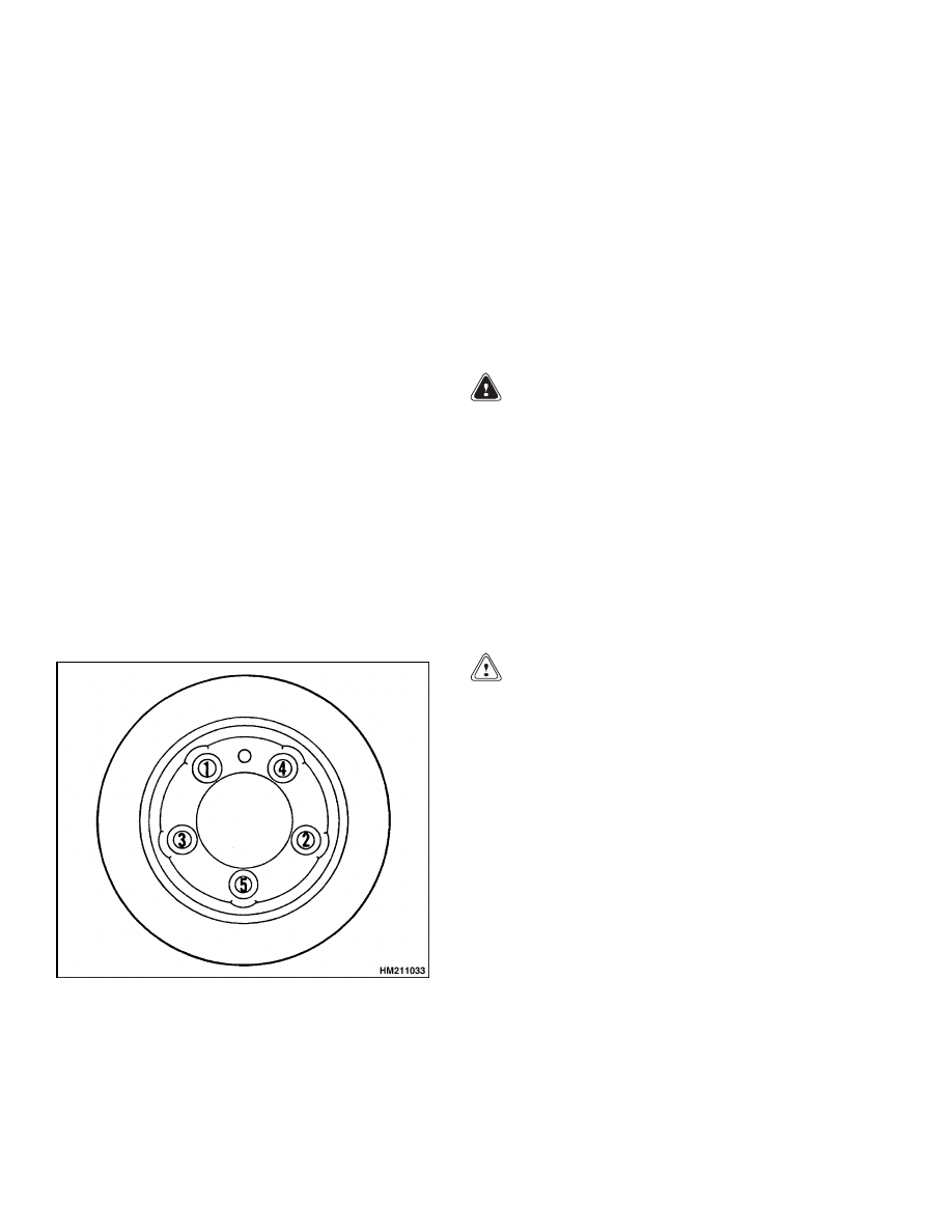
TIRE AND WHEEL ASSEMBLIES
Inspect the wheel rim for rust and cracks. Do not
weld a cracked wheel rim or straighten a bent rim.
Welding, heating, or bending a wheel rim can weaken
its capacity. Always replace damaged tires or wheel
rims immediately. Do not operate a truck with a bro-
ken stud or missing lug nuts. Tighten the fasteners
in a crisscross pattern to the correct torque value.
See Figure 10.
When the wheels have been removed and installed,
check all wheel nuts after 2 to 5 hours of operation.
Tighten the nuts in a cross pattern to the correct
torque value.
When the nuts stay tight after an
8-hour check, the interval for checking the torque
can be extended to every 500 hours or 3 months.
Figure 10. Torquing Pattern
MAST AND CARRIAGE
WARNING
Use special safety precautions when working
on or near the mast or carriage. See Safety Pro-
cedures When Working Near Mast.
Do not work under a raised carriage. Lower
the carriage or install a safety chain to prevent
the carriage from lowering when performing
maintenance on the mast and lift chains.
Cleaning solvents can be flammable and toxic
and can cause skin irritation.
When using
cleaning solvents, always follow the recom-
mendations of the manufacturer.
CAUTION
DO NOT use steam or high-pressure water to
clean the load rollers or the lift chains. Steam
and high-pressure water can remove the lu-
brication from the bearings in the load rollers.
Water in the bearings of the sheaves and the
link pins of chains can also shorten the service
life of these parts.
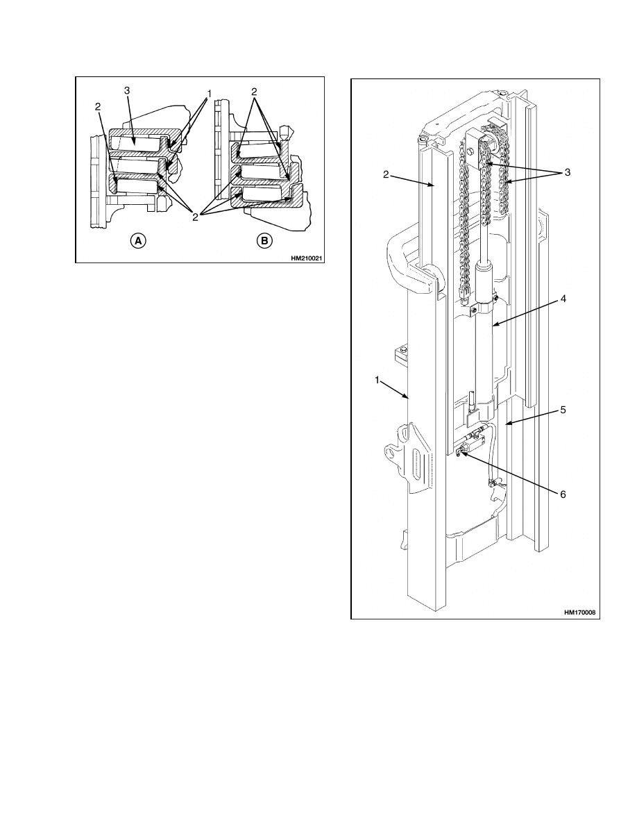
1.
Lubricate the sliding surfaces and the load roller
surfaces along the full length of the channels of
the mast and carriage as shown in Figure 11 and
Figure 12. Apply lubricant only to the indicated
surfaces.
NOTE: The load rollers and sheaves have sealed bear-
ings that do not need additional lubrication.
2.
Lubricate the mast pivots with multipurpose
grease at the grease fittings on the pivot pins.
16
8000 SRM 1079
Maintenance Procedures Every 500 Hours or 3 Months
A. UPPER LOAD ROLLERS
B. LOWER LOAD ROLLERS
1.
LUBRICATE STRIP BEARINGS SURFACES
2.
LUBRICATE SURFACES WHERE LOAD
ROLLERS TRAVEL
3.
LOAD ROLLER
Figure 11. Mast Lubrication
BATTERY
In addition to normal charging, the battery requires
an equalizing charge periodically. This is a charge at
a low rate to balance the charge of all the cells. The
equalizing charge is normally given approximately
once a month, but no more than once a week. Charge
the battery at a slow rate for three to six hours in
addition to the normal charging cycle. The most ac-
curate specific gravity measurements for a charged
battery will be after an equalizing charge. Check the
specific gravity of each cell. If the specific gravity dif-
ference is more than 0.020 between cells of the bat-
tery after an equalization charge, there may be a de-
fective cell. Consult your battery dealer if you sus-
pect a defective cell or other battery damage.
NOTE: TYPICAL MAST SHOWN.
1.
OUTER WELDMENT
2.
INNER WELDMENT
3.
FREE-LIFT CHAIN
4.
FREE-LIFT CYLINDER
5.
MAIN LIFT CYLINDER
6.
LOWERING CONTROL VALVE (EXTERNAL)
Figure 12. Two-Stage Mast With Full Free Lift
17
Maintenance Procedures Every 500 Hours or 3 Months
8000 SRM 1079
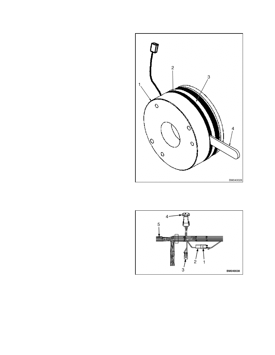
PARKING BRAKES
The
parking
brake
consists
of
two
identical
spring-applied/electrically-released brakes mounted
directly to the drive motors. The controller breaks
the power supply to the brake coils, engaging the
parking brake when the truck is stopped. Pressing
the emergency disconnect button will apply the
parking brake immediately in any mode of opera-
tion. The parking brake should be checked to ensure
proper operation. First, check the air gap between
the brake coil and the pressure plate using a feeler
gauge:
1.
Raise the mast so that the transaxle and brake
assemblies can be accessed. Install a safety chain
to the mast.
2.
Turn the key switch to the OFF position and dis-
connect the battery. Block the lift truck wheels
to prevent unexpected movement.
3.
Using a feeler gauge, measure the distance be-
tween the brake coil and the pressure plate on
each brake assembly. The measure should read
between 0.30 to 0.46 mm (0.011 to 0.018 in.). See
Figure 13.
4.
If the air gap is larger than allowed, the friction
surfaces are excessively worn. An air gap that
is too small signifies damage to internal compo-
nents or foreign objects inside the brake. In ei-
ther case, repair or replace the brake assembly.
Refer to Brake System 1800 SRM 1076.
5.
Test the lift truck to ensure that the parking
brake is performing to the proper specification.
This is accomplished by driving a lift truck up
a specified grade, stopping the truck using the
service brakes, and then releasing the service
brakes to check if the parking brakes can hold
the truck on the grade.
6.
If the air gap is correct and the parking brake
cannot hold the truck on the grade, move the
truck to a safe, level location and clean the fric-
tion disks on each brake assembly using stan-
dard automotive brake cleaner:
a. Locate
the
parking
brake
connectors
(BRK_RUN
1,
BRK_RUN
2,
and
the
BRK_TOWING) beside the brake diode
on the main wiring harness. These items are
found near the front, right wheel well. See
Figure 14.
1.
BRAKE COIL
2.
AIR GAP
3.
PRESSURE PLATE
4.
FEELER GAUGE
Figure 13. Air Gap Measure
1.
BRK_RUN 1
2.
BRK_RUN 2
3.
BRK_TOWING
4.
BRAKE DIODE
5.
MAIN WIRING HARNESS
Figure 14. Brake Diode and Release Connectors
18
8000 SRM 1079
Maintenance Procedures Every 500 Hours or 3 Months
b. If a charged battery is not installed in the
lift truck, use special tool - Auxiliary Bat-
tery Connector (Hyster™ P/N 1564329) and
an auxiliary 24-volt power supply to energize
the brake override circuit:
(1)
Disconnect
the
BRK_RUN
1
and
BRK_RUN 2 connectors.
(2)
Connect the auxiliary battery connector
to the BRK_RUN 2 connector.
(3)
Connect the jumper wires to the 24-volt
auxiliary power source and listen for
the parking brakes to release.
c.
If a charged battery is installed in the lift
truck, use the BRK_TOWING connector to
energize the brake override circuit:
(1)
Disconnect
the
BRK_RUN
1
and
BRK_RUN 2 connectors.
(2)
Connect
the
BRK_TOWING
and
BRK_RUN 2 connectors.
(3)
Pull the emergency disconnect switch
to the RUN position and listen for the
parking brakes to release.
d. Spray thoroughly between the pressure plate
and the mounting plate of the brake assem-
bly using standard automotive brake cleaner.
e.
Return the brake connectors to the normal
operating mode and test the parking brakes
again:
(1)
Push the emergency disconnect switch
to the OFF position.
(2)
Disconnect the BRK_TOWING and
BRK_RUN 2 connectors.
(3)
Reconnect
the
BRK_RUN
1
and
BRK_RUN 2 connectors.
f.
Retest the parking brake for proper hold on
grade. If the parking brakes do not hold to
specification, repair or replace the parking
brake assemblies. Refer to Brake System
1800 SRM 1076.
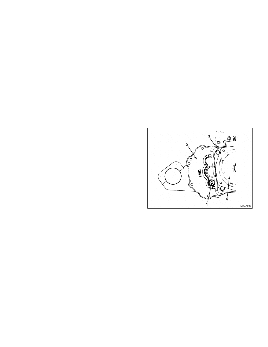
TRANSAXLE
Each transaxle has its separate oil supply. See Fig-
ure 15. Make sure the lift truck is parked in a level
area. Remove the oil fill plug to check the level of
the oil. The oil should be level with the bottom of the
hole. If it is necessary to add oil, add oil through the
fill plug hole until the oil is level with the bottom of
the hole. Replace the oil fill plug. Torque to 40 N•m
(30 lbf ft).
Check the oil level separately in each transaxle.
1.
OIL FILL PLUG
2.
R. H. TRANSAXLE
3.
TRACTION MOTOR
4.
PARKING BRAKE
Figure 15. Transaxle Oil Level
19
Maintenance Procedures Every 1000 Hours or 6 Months
8000 SRM 1079
Maintenance Procedures Every 1000 Hours or 6 Months
LIFT CHAINS
WARNING
When working on or near the mast or carriage,
refer to Safety Procedures When Working Near
Mast in this section.
Do not work under a raised carriage. Lower
the carriage or use a safety chain to prevent
the carriage from lowering when doing main-
tenance on the mast and lift chains.
1.
Lubricate the lift chains with SAE 20 or 30 en-
gine oil. For best results, remove the chains from
the lift truck and soak them in oil.
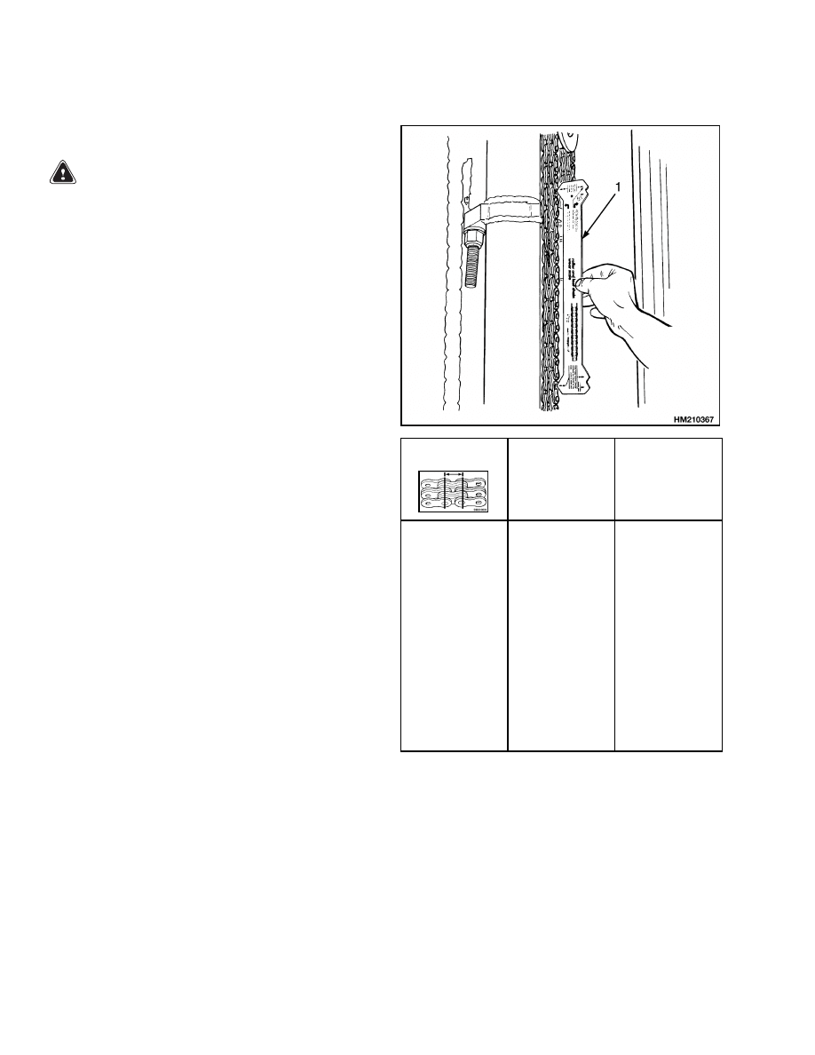
2.
If a section of chain is 3 percent longer than a
similar section of new chain, the chain is worn
and must be replaced. If a chain scale is avail-
able, check the lift chains as shown in Figure 16.
If a chain scale is not available, measure 20 links
of chain. Measure from the center of a pin to the
center of another pin 20 pitches away. Compare
the length with the chart in Figure 16. Replace
the chain if the length of 20 links of the worn sec-
tion is more than the maximum wear limit.
HYDRAULIC BREATHER CAP
The hydraulic breather cap allows air to enter the
hydraulic tank when the hydraulic oil is pumped
out to the cylinders. When the hydraulic oil returns
to the tank, air is expelled through the hydraulic
breather cap. A filter in the cap protects the hy-
draulic system from particles of dirt and other
contaminants.
If the filter becomes excessively
dirty, air flow can be restricted, causing pressures
and vacuums to build inside the tank. If air flow
becomes restricted through the hydraulic breather
cap, replace the assembly. Keep the hydraulic tank
area clean and do not overfill the hydraulic tank.
Pitch
Total length of
20 links (pitch)
of new chain
Wear Limit
The maximum
length of 20
links.
12.7 mm
(0.50 in.)
15.9 mm
(0.63 in.)
19.1 mm
(0.75 in.)
25.4 mm
(1.00 in.)
31.8 mm
(1.25 in.)
44.5 mm
(1.75 in.)
50.8 mm
(2.00 in.)
254.0 mm
(10.0 in.)
317.5 mm
(12.5 in.)
381.0 mm
(15.0 in.)
508.0 mm
(20.0 in.)
635.0 mm
(25.0 in.)
889.0 mm
(35.0 in.)
1016.0 mm
(40.0 in.)
261.6 mm
(10.3 in.)
327.0 mm
(12.9 in.)
392.4 mm
(15.4 in.)
523.3 mm
(20.6 in.)
654.1 mm
(25.75 in.)
915.7 mm
(36.05 in.)
1046.5 mm
(41.2 in.)
NOTE: THE INSTRUCTIONS FOR MEASURING
CHAIN WEAR ARE SHOWN ON THE CHAIN WEAR
SCALE.
1.
CHAIN WEAR SCALE
Figure 16. Lift Chains Check
20

8000 SRM 1079
Maintenance Procedures Every 1000 Hours or 6 Months
MASTER CYLINDER
WARNING
Loss of fluid from the master cylinder indicates
a leak. This condition can cause brake failure,
resulting in material damage or personal in-
jury. Repair the brake system before return-
ing to service if a leak is suspected. Drain and
flush the service brake system when contami-
nated by dirt, water, or other unapproved flu-
ids.
The service brake system is a self-contained sys-
tem filled with hydraulic oil and does not require
frequent service. However, normal operation does
use a small amount of hydraulic fluid and must be
checked and refilled at the 1000-hr/6-month interval.
A float switch inside the master cylinder reservoir
activates an indicator light on the display panel
if the hydraulic oil drops below the minimum safe
level between checks, as in the case of a leak. The
reservoir, mounted on top of the master cylinder,
stores a small amount of hydraulic oil to compensate
for normal loss. Remove the floor plates. Locate
the master cylinder assembly near the brake pedal.
Remove the reservoir cap and fill the reservoir to
the full mark with hydraulic oil. See Maintenance
Schedule in this section. Reinstall the reservoir cap
and check for leaks. If there is a leak or if the fluid
level has dropped below the minimum safe level,
the system may need to be bled before returning to
service. See Brake System 1800 SRM 1076.
ELECTRICAL INSPECTION
Hydraulic Motor Brushes
The hydraulic motor is the only DC motor used on
this truck. Hence, it is the only motor which has
brushes which must be checked periodically and
changed as required.
If the motor brushes wear
below the minimum safe length during operation, a
status code will appear on the LCD screen of the dis-
play panel to alert the operator. However, inspecting
the brushes is necessary to prevent brush-related
failures during operation. Repairing the brushes is
convenient during the 1000-hr/6-month checks when
the truck is not scheduled to be in service.
1.
Visually inspect the commutator and brushes.
Make sure the surface of the commutator is good
and the motor operates normally. Worn motor
brushes must be replaced before they damage the
surface of the commutator.
2.
Move the brush spring and remove a brush from
the brush holder.
When the brush wears to
within 1.5 mm (0.60 in.) of where the brush wire
joins the brush, the brush must be replaced.
The brush spring makes a contact when the
brush is worn to the length where it must be
replaced. A status code will appear on the LCD
screen as an indication that the brushes must be
replaced.
3.
Inspect the brush holders for burns or damage.
Make sure the brush holder is fastened tightly to
the mounts at the end of the motor. Make sure
the brushes will move freely and smoothly in the
brush holders.
4.
Check the brush springs for damage from heat
and corrosion.
Replace any damaged brush
springs.
See the service manual section DC Motor Mainte-
nance 620 SRM 294 for additional information to in-
spect the commutator and brushes.
Contactors
WARNING
Disconnect the battery and discharge the ca-
pacitors when working in the electrical com-
partment.
WARNING
DO NOT file or lubricate the contacts. This may
cause the contacts to stick, resulting in loss of
control and damage to property or personal in-
jury.
Inspect the contacts inside the contactors. Discon-
nect the battery and discharge the capacitors. Re-
move the contactors from the electrical compartment
and disassemble. The contacts are made of a special
silver alloy. The contacts will tarnish (appear black
and rough) over time. This condition occurs with nor-
mal operation of the lift truck and requires no ser-
vice. Cleaning is not necessary. Check for grooves,
pits, and weld mark on the contacts. Damaged con-
tacts cannot be repaired and must be replaced. Al-
ways replace the contacts in sets.
21
Maintenance Procedures Every 1000 Hours or 6 Months
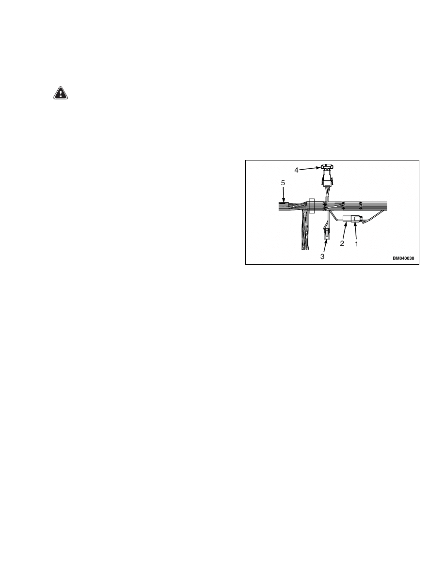
8000 SRM 1079
Directional Speed Control
The directional speed control lever is located on the
left side of the steering column on standard models.
It is attached to linkage inside the steering column
through a notch in the steering column covers. Re-
move the steering column covers.
See Steering
System 1600 SRM 1075, Steering Wheel and Col-
umn Assembly. Inspect the linkage and directional
control switches for damage and excessive wear.
Lubricate the linkage using silicone spray lubricant
and work the directional control lever back and
forth to ensure complete coverage. Foot-controlled
directional switches mounted to the top of the ac-
celerator pedal are available as an option. These
models do not utilize a lever on the steering column.
See Figure 17.
1.
DIRECTIONAL CONTROL LEVER
2.
DIRECTIONAL CONTROL SWITCHES
3.
WIRING HARNESSES AND CONNECTORS
Figure 17. Directional Control Assembly
The accelerator is located on the floor of the opera-
tor’s compartment. Remove the floormat and floor
plates and lubricate the accelerator pedal pivots us-
ing silicone spray lubricant and work the pedal back
and forth to ensure complete coverage.
TRANSAXLE, OIL CHANGE
WARNING
Oil is hot at normal operating temperatures.
Be careful when draining oil.
CAUTION
Disposal of lubricants and fluids must meet lo-
cal environmental regulations.
NOTE: Operate the lift truck for 5 minutes or until
the transaxle is warm to the touch. Oil is thick and
will drain easier and more thoroughly when it is
warm. Each transaxle uses separate, self-contained
oil supplies.
The oil in the transaxle should be
changed every 2000 hours or yearly.
1.
Raise and safety chain the mast to access the
transaxle assemblies.
See Safety Procedures
When Working Near Mast. Disconnect the bat-
tery and block the wheels to prevent unexpected
movement.
2.
Place a drip pan with at least a 3.8 liter (1 gal)
capacity under each transaxle.
3.
Remove the fill and drain plugs on each
transaxle. See Figure 18 and Figure 19.
1.
OIL FILL PLUG
2.
R.H. TRANSAXLE
3.
TRACTION MOTOR
4.
PARKING BRAKE
Figure 18. Transaxle Oil Fill Plug
22
8000 SRM 1079
Maintenance Procedures Every 2000 Hours or Yearly
1.
BRAKE BLEED VALVE
2.
TRANSAXLE HOUSING
3.
DRAIN PLUG
Figure 19. Transaxle Drain Plug
4.
After both transaxles have drained completely,
replace the drain plugs and remove the drip
pans. Torque drain plugs to 40 N•m (30 lbf ft).
5.
Fill the transaxles with oil until level with the
bottom of the fill holes.
6.
Install the oil fill plugs. Torque oil fill plugs to
40 N•m (30 lbf ft).
Maintenance Procedures Every 2000 Hours or Yearly
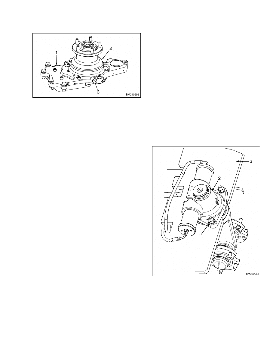
STEERING
The steering actuator is mounted to the rear of
the frame below the counterweight.
The steering
tire and wheel assemblies and the actuator sup-
port much of the weight of the battery, frame, and
counterweight. The action of steering pushes and
pulls on the actuator in various directions.
The
hardware attaching the actuator to the frame should
be checked to ensure proper torques every 2000
hours or yearly.
Position the lift truck on blocks
with the steering tire and wheel assemblies raised
off the floor.
Check that the steering actuator is
securely mounted to the frame by tightening the
attaching hardware to the proper torque. If there is
play between these components, remove the nuts,
washers, and mounting capscrews from the actuator
one at a time. Apply Loctite™ 271 to the threads of
each mounting capscrew and reinstall. The proper
torque for the steering actuator attaching hardware
is 290 N•m (215 lbf ft). See Figure 20.
1.
ATTACHING HARDWARE
2.
STEERING ACTUATOR
3.
FRAME
Figure 20. Steering Actuator Mounting
23
Maintenance Procedures Every 2000 Hours or Yearly
8000 SRM 1079
HYDRAULIC
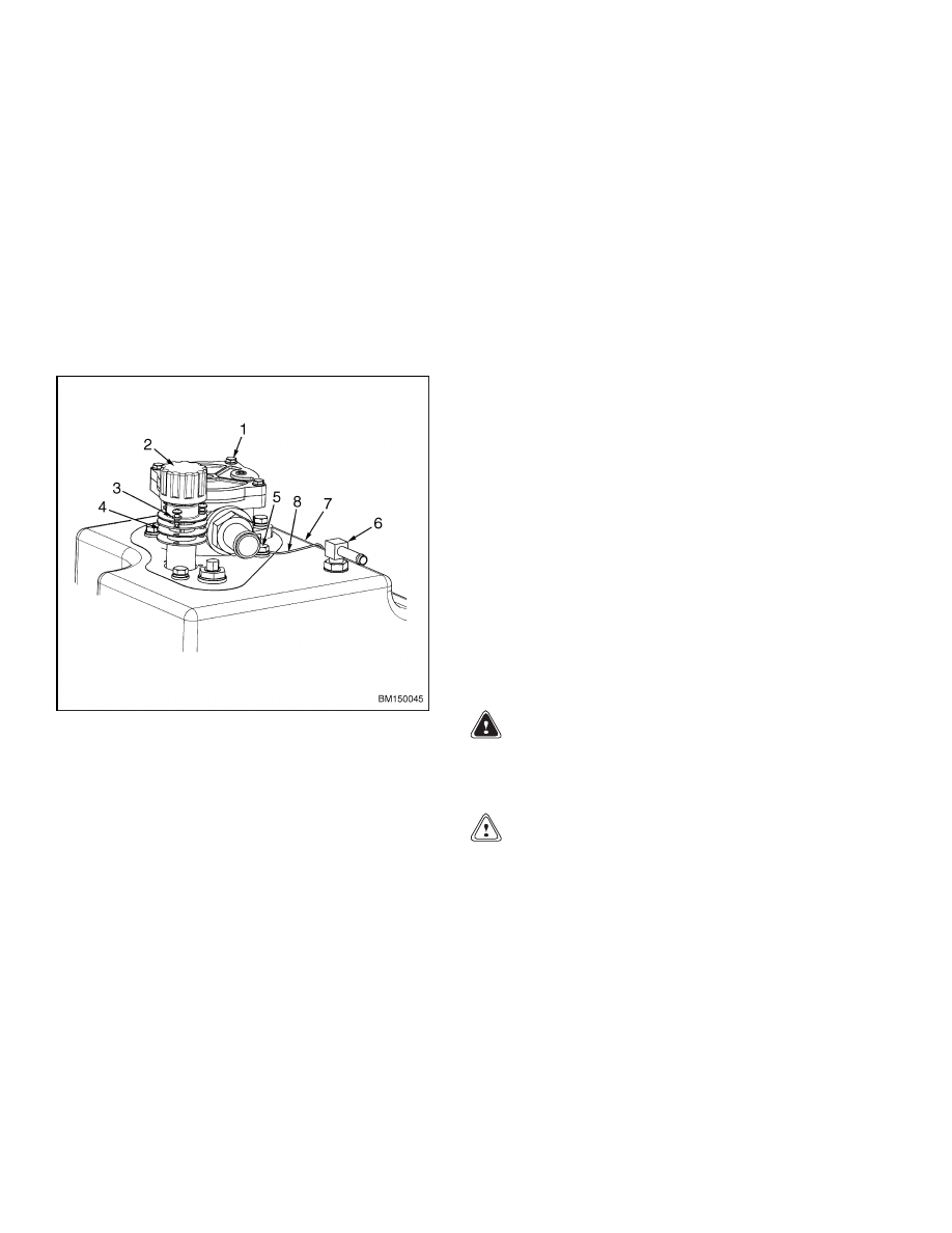
Hydraulic Oil Filter, Change
Replace the filter element after the first 50 hours of
service and every 2000 hours or yearly after that. See
Figure 21.
1.
Loosen the four capscrews (1) securing cover to
the hydraulic oil filter housing located on top of
the hydraulic oil tank.
2.
Press down on the cover while removing the cap-
screws to depress the element retainer spring.
1.
CAPSCREW
2.
BREATHER CAP/DIPSTICK
3.
SCREW AND LOCKWASHER
4.
STRAINER ASSEMBLY
5.
CAPSCREW, LOCKWASHER, AND WASHER
6.
STEERING SUPPLY
7.
HYDRAULIC TANK
8.
GROUND WIRE
Figure 21. Hydraulic Tank Assembly
3.
Remove the cover and spring from housing.
Check O-ring seal on the cover for cracks or
deterioration. Replace if damaged.
4.
Remove element from housing and replace with
a new element.
5.
Install the cover and spring to the housing using
four capscrews. Press the cover down onto the
housing while installing the capscrews. Torque
capscrews to 6 N•m (53 lbf in).
6.
Clean the breather cap/dipstick. See Figure 21.
Hydraulic Oil Strainer, Check
Remove the breather cap/dipstick from the top of the
hydraulic tank. Visually inspect the hydraulic oil
strainer located inside the fill hole. The screen must
be kept clean in order to strain the new oil added to
the system. If dirt, trash, rust, or sludge is present,
clean the strainer. If the strainer cannot be cleaned
or is broken, it should be replaced. See Figure 21.
1.
Remove the breather cap/dipstick.
2.
Remove the three screws and lockwashers (3) re-
taining the strainer assembly to the hydraulic
tank.
3.
Remove the strainer assembly from the tank.
4.
Clean or replace the strainer. Check the gaskets
for damage. Replace if necessary.
5.
Install the housing and strainer assembly to the
tank.
6.
Install the three screws and lockwashers (3) re-
taining the hydraulic oil strainer and gaskets to
the hydraulic tank.
7.
Install the breather cap/dipstick.
Hydraulic Oil, Change
WARNING
The hydraulic oil is hot at normal operating
temperatures. Be careful when draining hot
oil.
CAUTION
Disposal of lubricants and fluids must meet lo-
cal environmental regulations.
The hydraulic oil should be changed every 2000
hours or yearly. When the hydraulic system compo-
nents such as the pump or steering control unit have
been damaged or the oil has otherwise been con-
taminated, the hydraulic system should be drained,
flushed, and refilled with new hydraulic oil.
1.
Put the lift truck on a level surface and lower the
mast.
24

8000 SRM 1079
General Repairs
2.
Turn the key switch to the OFF position and dis-
connect the battery. Block the wheels to prevent
unexpected movement.
3.
Remove the floormat and floor plates.
4.
Remove the breather cap/dipstick to allow faster
draining.
5.
Locate the hydraulic tank drain hose. Clip the
wire tie retaining the hose using wire cutters and
route it under the side of the frame to the outside
of the lift truck. Position the hose to drain into a
container suitable for storing used hydraulic oil
with a minimum capacity of 19 liter (5 gal).
6.
Remove the hose clamp and drain plug from the
end of the hydraulic tank drain hose to drain the
hydraulic oil.
7.
When the oil has drained, reinstall the drain plug
into the hose and secure with hose clamp.
8.
Coil hose and secure below the floor plates using
a new wire tie.
NOTE: Check the hydraulic oil level by wiping the
dipstick clean and install the breather cap/dipstick
on to the tank. Remove again and check the oil level
on the dipstick.
9.
Fill the hydraulic tank to the proper level with
new hydraulic oil.
DO NOT overfill the hy-
draulic tank.
10. Install the breather cap/dipstick.
11. Operate the lift pump for 1 to 2 minutes to purge
air from the hydraulic system; then recheck the
hydraulic oil level.
12. Install the floormat and floor plates.
General Repairs
WELDING REPAIRS
WARNING
Remove the battery and disconnect the battery
connector before welding. Welding can cause a
fire and/or an explosion. Make sure there is no
fuel, oil, or grease near the weld area. Make
sure the area is well ventilated.
WARNING
Forklift truck frames and components may
have polyurethane paint. Welding, burning, or
other heat sufficient to cause thermal decom-
position of the paint may release isocyanates.
These chemicals are allergic sensitizers to
skin and respiratory tract and overexposure
may occur without odor warning. When per-
forming work, utilize good industrial hygiene
practices, including removal of all paint (prime
and finish coats) to the metal around the area
to be welded.
Use local ventilation, and/or
supplied-air respiratory protection.
CAUTION
Always disconnect the battery connector to
prevent
damage
to
electrical
components
when welding.
Connect the welding ground
clamp as close to the weld area as possible to
prevent welding current from straying.
Only properly trained, authorized technicians should
perform welding repairs.
25

Lift and Tilt System Leak Check
8000 SRM 1079
PAINTING INSTRUCTIONS
WARNING
Always use solvents and paints in an area with
adequate ventilation. Do not use solvents or
paints near heat, fire, or electrical equipment
that can make sparks.
Follow the manufac-
turer’s instructions and cautions.
CAUTION
DO NOT put tape on cylinder rods to protect
from paint. Use a thick layer of multipurpose
grease to protect cylinder rods. Cylinders can
be damaged if operated with tape on the cylin-
der rod.
1.
Clean the surface to be painted. Use a solvent
on surfaces to be painted to remove grease and
oil before sanding. DO NOT use solvent to clean
new paint. Make sure all oil and grease is re-
moved.
2.
Use sandpaper to remove the top surface of
paint and rust from the metal. All metal sur-
faces where the paint is removed to the bare
metal must be primed. Apply primer BEFORE
applying the paint.
3.
Protect all surfaces that will not be painted.
DO NOT paint:
Pedal Pads
Lever Knobs
Instrument Panel
Steering Wheel
Labels and Information Plates
Seat Assembly and Rails
Information Case
Tires
Chains and Hoses
Battery Connector
Key Switch
Cylinder Rods
All Plastic Covers
Pumps and Motors
Control Valve
Wiring Harnesses or Connectors
CAUTION
Do not paint the pads, plastic covers or knobs,
cables, labels, information plates, or controls.
Paint can cause some assemblies to operate in-
correctly.
NOTE: Use colors approved by Hyster Company.
4.
Paint the surfaces. Use the proper paint from
your local Hyster lift trucks dealer. Follow the
directions on the container. Allow the paint to
dry according to the manufacturer’s directions.
WARNING
Make sure ALL safety labels are installed.
5.
Install the safety labels and decals in the correct
locations on the lift truck. Safety labels and de-
cals are installed on the lift truck to identify the
lift truck and its specifications and to give in-
formation about possible hazards. It is impor-
tant that ALL decals and safety labels are in-
stalled on the lift truck and can be easily read.
See Frame 100 SRM 1073 for proper label place-
ment.
Lift and Tilt System Leak Check
LIFT SYSTEM
WARNING
Special precaution is required when working
on or near the mast or carriage. See Safety Pro-
cedures When Working Near Mast.
Never allow anyone under a raised carriage.
Do not put any part of your body in or through
the lift mechanism unless all parts of the mast
are completely lowered, the key is removed,
and the battery is disconnected.
Do not try to find hydraulic leaks by putting
hands on pressurized hydraulic components.
Hydraulic oil can be injected into the body by
pressure, resulting in serious injury.
During the test procedures for the hydraulic
system, fasten the load to the carriage with
chains to prevent it from falling.
Keep all
personnel away from the lift truck during the
tests.
26

8000 SRM 1079
Lift and Tilt System Leak Check
1.
Place a capacity load (refer to the lift truck name
plate) on the forks and secure with chains. Oper-
ate the hydraulic system by raising and lowering
the load several times. Lower the load, and tilt
the mast forward and backward several times.
Visually inspect for leaks.
2.
Raise the carriage and the load 1 m (3 ft). If the
carriage lowers slowly with the control valve in a
neutral position, there are leaks inside the hy-
draulic system. The maximum speed that the
carriage is allowed to lower is 50 mm (2 in.) per
10 minutes when the hydraulic oil is 30 C (90 F).
If the oil temperature is 70 C (160 F), the maxi-
mum speed that the carriage can lower is 150 mm
(6 in.) per 10 minutes.
3.
If the leak rate is greater than specifications, iso-
late the lift cylinders to check for internal leaks.
Remove the load from the forks and install a gate
valve in the supply line between the main control
valve and the mast. Put a capacity load on the
forks again. Raise the carriage 1 m (3 ft). Close
the gate valve. If the carriage or mast weldments
continue to lower, the seals in the lift cylinders
have leaks.
4.
If the carriage does not move, open the gate valve
and check for movement again. If the carriage
lowers when the valve is open, check for leaks
in the hydraulic lines or fittings. If there are no
external leaks, the main control valve might be
damaged. Remove the load from the forks and
troubleshoot the hydraulic system.
TILT SYSTEM
WARNING
Special precaution is required when working
on or near the mast or carriage. See Safety Pro-
cedures When Working Near Mast.
Never allow anyone under a raised carriage.
Do not put any part of your body in or through
the lift mechanism unless all parts of the mast
are completely lowered, the key is removed,
and the battery is disconnected.
Do not try to find hydraulic leaks by putting
hands on pressurized hydraulic components.
Hydraulic oil can be injected into the body by
pressure, resulting in serious injury.
During the test procedures for the hydraulic
system, fasten the load to the carriage with
chains to prevent it from falling.
Keep all
personnel away from the lift truck during the
tests.
1.
Place a capacity load on the forks and secure with
chains. Operate the hydraulic system by rais-
ing and lowering the load several times. Lower
the load, and tilt the mast forward and backward
several times. Visually inspect for leaks.
2.
Slowly tilt the mast forward. If the mast contin-
ues to slowly tilt forward when the control valve
is in a neutral position, there are leaks inside the
hydraulic system. The maximum speed that the
mast is allowed to tilt forward when there are in-
ternal leaks in the lift system is 13 mm (0.50 in.)
per 10 minutes (measured at the tilt cylinder).
This maximum speed is measured when the hy-
draulic oil is 30 C (90 F). If the oil temperature
is 70 C (160 F), the maximum speed is 39 mm
(1.5 in.) per 10 minutes.
3.
If the leak rate is greater than specifications, iso-
late the tilt cylinders to check for internal leaks.
Remove the load from the mast. Install a gate
valve between the port at the front of the tilt
cylinder and the hydraulic line. Secure the load
on the forks again and repeat Step 2. Close the
gate valve. If the mast continues to tilt forward,
the cylinder seals are leaking.
4.
If the mast does not move, open the gate valve
and check for movement again.
If the mast
moves forward when the gate valve is open,
check for leaks in the hydraulic lines or fittings.
If there are no external leaks, the main control
valve might be damaged. Remove the load from
the forks and troubleshoot the hydraulic system.
27
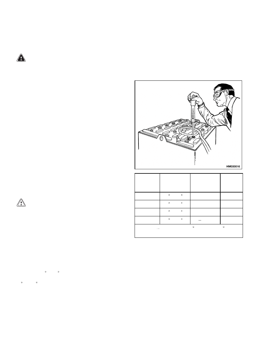
Battery Maintenance
8000 SRM 1079
Battery Maintenance
HOW TO CHARGE BATTERY
WARNING
If the lift truck was operated with a low battery,
check all contactors for welded contacts before
a charged battery is connected.
Make sure the key switch is in the OFF position
before connecting the battery.
The electrolyte in the battery contains acid
that can cause injury. If electrolyte is spilled,
use a solution of water and soda to neutralize
the acid. Flush areas where acid is spilled on
the skin with water. Acid in the eyes must be
continuously flushed with water for 15 min-
utes. Batteries generate explosive fumes when
they are being charged.
Keep fire, sparks,
and burning material away from the battery
charger area. Avoid sparks from the battery
connections.
Charge batteries only in the
designated area.
When the battery is being
charged, keep the vent caps clear. The battery
charger area must have adequate ventilation
to remove fumes. Keep the battery cover open
and the top of the battery clear. Disconnect
the battery when cleaning and performing
maintenance.
CAUTION
Never connect the battery charger plug to
the plug of the lift truck; you can damage the
electronic controller.
Make sure the battery
charger voltage is the correct voltage for the
battery.
Correct use of the hydrometer, and proper operation
of the battery charger, is important. See Figure 22.
Follow the instructions of the charger manufacturer.
Never let the battery discharge below the minimum
value given by the battery manufacturer. A fully
charged battery will have a specific gravity of 1.265
to 1.310 at 25 C (77 F). Never charge a battery at a
rate that will raise the electrolyte temperature above
49 C (120 F). Never let a battery stay discharged for
long periods.
NORMAL CHARGE: This is the charge that is nor-
mally given to a battery that is discharged from nor-
mal service. Many users give this charge at a regular
interval based on usage. This practice will keep the
battery fully charged if the battery is not discharged
below the limit. Always use a hydrometer to check
the battery if the interval charge cycle is used. Fre-
quent charging of a battery that has a 2/3 or more
charge can decrease battery life.
Specific
Gravity
Reading
Electrolyte
Temp.
Correction
Points
Correct
Value
1.210
31 C (88 F)
+0.003
1.213
1.210
27 C (81 F)
+0.001
1.211
1.210
25 C (77 F)
0.000
1.210
1.210
18 C (64 F)
0.004
1.206
+0.001 or
0.001 for each 2 C from the 25 C base
value.
Figure 22. Battery Check
NOTE: Some batteries are maintenance free and do
not require checking the electrolyte. Do not attempt
to check electrolyte in batteries with sealed cells.
EQUALIZING CHARGE: This charge is at a low rate
and balances the charge in all of the cells. The equal-
izing charge is normally given approximately once a
month. It is a charge at a slow rate for 3 to 6 hours
in addition to the regular charging cycle.
28
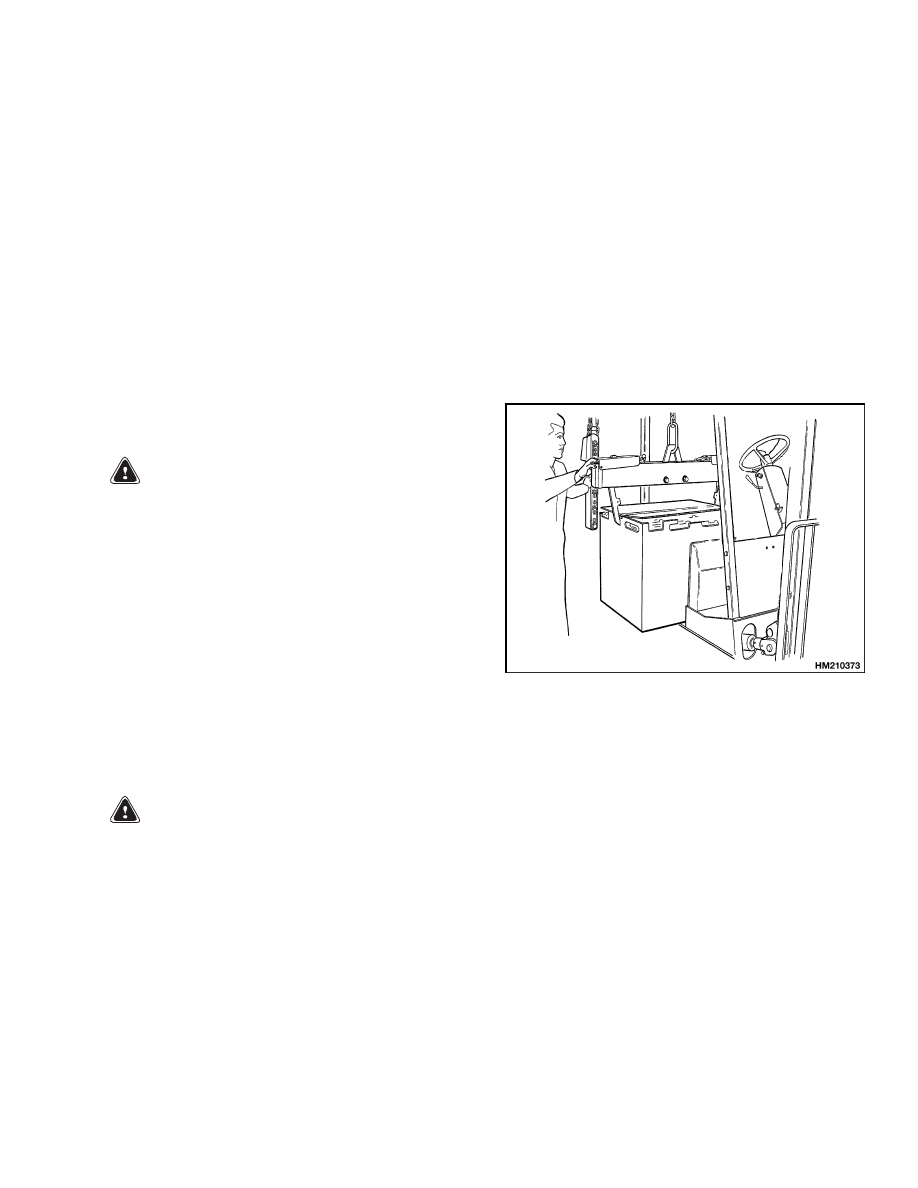
8000 SRM 1079
Battery Maintenance
Do NOT give an equalizing charge more than once
a week.
The most accurate specific gravity mea-
surements for a charged battery will be after an
equalizing charge. If the specific gravity difference
is more than 0.020 between cells of the battery after
an equalizing charge, there may be a defective cell.
Consult your battery dealer.
See the section Industrial Battery 2240 SRM 1 for
additional information on the charging and mainte-
nance of a battery.
NOTE: Many users have battery chargers that can
follow a program to automatically charge a battery
according to recommendations of the battery man-
ufacturer. Use the recommendations of the battery
manufacturer for charging the battery.
HOW TO CHANGE BATTERY
WARNING
Make sure the capacity of the crane and
spreader bar is greater than the weight of the
battery. The weight of the battery is normally
shown on the battery case. The spreader bar
must NOT be made of metal or it must have
insulated straps.
Batteries are heavy. Use care to avoid injury.
The replacement battery must fit the battery
area correctly. Use spacers to prevent the bat-
tery from shifting inside the battery compart-
ment.
Make sure the weight of the replacement bat-
tery is within the maximum and minimum
weights shown on the Nameplate.
WARNING
Make sure the key switch is in the OFF position
before connecting the battery.
1.
Disconnect the battery. Move the steering wheel
to its top position. Move the seat backward to its
rear adjustment position. See Figure 23.
2.
Release the hydraulic control cover, and raise the
hydraulic controls and the cover for access to the
hood latch. Disengage the hood latch and raise
the battery cover. The gas-filled, double-damp-
ened strut will help raise the hood and hold the
battery cover in the open position for access to
the battery.
3.
Move the connector and cables so they will not be
damaged when the battery is moved.
4.
Use a spreader bar and overhead lifting device
to lift the battery from the lift truck. When a
replacement battery is installed, make sure the
battery is the correct size and weight for the lift
truck. See the Nameplate.
Figure 23. Changing Battery
BATTERY SIZE SPECIFICATIONS
Batteries function as part of the lift truck’s counter-
weight system. Installing a battery that is too small
can leave the lift truck lacking sufficient weight to
counter the rated load. Refer to the nameplate when
replacing a battery to verify the truck rating to en-
sure that the battery (and spacer if so equipped) is
of the proper size. See Capacities and Specifica-
tions 8000 SRM 1080 for exact battery specifications
for your truck.
29

NOTES
____________________________________________________________
____________________________________________________________
____________________________________________________________
____________________________________________________________
____________________________________________________________
____________________________________________________________
____________________________________________________________
____________________________________________________________
____________________________________________________________
____________________________________________________________
____________________________________________________________
____________________________________________________________
____________________________________________________________
____________________________________________________________
____________________________________________________________
____________________________________________________________
____________________________________________________________
____________________________________________________________
____________________________________________________________
____________________________________________________________
30


TECHNICAL PUBLICATIONS
8000 SRM 1079
6/04 Printed in United Kingdom
Document Outline
- toc
- Periodic Maintenance
- Safety Precautions Maintenance and Repair
- Introduction
- Safety Procedures When Working Near Mast
- Maintenance Schedule
- Maintenance Procedures Every 8 Hours or Daily
- Maintenance Procedures Every 500 Hours or 3 Months
- Maintenance Procedures Every 1000 Hours or 6 Months
- Maintenance Procedures Every 2000 Hours or Yearly
- General Repairs
- Lift and Tilt System Leak Check
- Battery Maintenance
- tables
Wyszukiwarka
Podobne podstrony:
1565454 8000SRM1113 (06 2004) UK EN
1554636 8000SRM1080 (11 2004) UK EN
1554632 2000SRM1086 (06 2004) UK EN
1554630 1900SRM1077 (06 2004) UK EN
1510478 8000SRM0988 (06 2005) UK EN
1554631 2000SRM1085 (03 2004) UK EN
1456997 8000SRM0708 (10 2004) UK EN
1467764 8000SRM0738 (05 2004) UK EN
897494 1900SRM0513 (06 2004) UK EN
1554626 0100SRM1073 (06 2004) UK EN
897559 0100SRM0545 (06 2004) UK EN
1553986 8000SRM1083 (05 2004) UK EN
więcej podobnych podstron