CAPACITIES AND
SPECIFICATIONS
H3.50-5.50XM (H70-120XM) [K005, L005]
PART NO. 1467764
8000 SRM 738

SAFETY PRECAUTIONS
MAINTENANCE AND REPAIR
• When lifting parts or assemblies, make sure all slings, chains, or cables are correctly
fastened, and that the load being lifted is balanced. Make sure the crane, cables, and
chains have the capacity to support the weight of the load.
• Do not lift heavy parts by hand, use a lifting mechanism.
• Wear safety glasses.
• DISCONNECT THE BATTERY CONNECTOR before doing any maintenance or repair
on electric lift trucks. Disconnect the battery ground cable on internal combustion lift
trucks.
• Always use correct blocks to prevent the unit from rolling or falling. See HOW TO PUT
THE LIFT TRUCK ON BLOCKS in the Operating Manual or the Periodic Mainte-
nance section.
• Keep the unit clean and the working area clean and orderly.
• Use the correct tools for the job.
• Keep the tools clean and in good condition.
• Always use HYSTER APPROVED parts when making repairs. Replacement parts
must meet or exceed the specifications of the original equipment manufacturer.
• Make sure all nuts, bolts, snap rings, and other fastening devices are removed before
using force to remove parts.
• Always fasten a DO NOT OPERATE tag to the controls of the unit when making repairs,
or if the unit needs repairs.
• Be sure to follow the WARNING and CAUTION notes in the instructions.
• Gasoline, Liquid Petroleum Gas (LPG), Compressed Natural Gas (CNG), and Diesel fuel
are flammable. Be sure to follow the necessary safety precautions when handling these
fuels and when working on these fuel systems.
• Batteries generate flammable gas when they are being charged. Keep fire and sparks
away from the area. Make sure the area is well ventilated.
NOTE:
The following symbols and words indicate safety information in this
manual:
WARNING
Indicates a condition that can cause immediate death or injury!
CAUTION
Indicates a condition that can cause property damage!

Capacities and Specifications
Table of Contents
TABLE OF CONTENTS
Lift Truck Weights .............................................................................................................................................
Electrical System ...............................................................................................................................................
Stall Speeds ........................................................................................................................................................
Capacities ...........................................................................................................................................................
Tire Pressure ......................................................................................................................................................
Engine Specifications.........................................................................................................................................
Transmission Oil Pressures...............................................................................................................................
Hydraulic System...............................................................................................................................................
Mast Speeds .......................................................................................................................................................
Torque Specifications .........................................................................................................................................
Brake System.................................................................................................................................................
Differential.....................................................................................................................................................
Drive Axle ......................................................................................................................................................
Engine, GM V-6 4.3 Liter ..............................................................................................................................
Engine, Perkins 1004-42 ...............................................................................................................................
Frame .............................................................................................................................................................
Lift Cylinders .................................................................................................................................................
Main Control Valve........................................................................................................................................
Masts ..............................................................................................................................................................
Powershift Transmission...............................................................................................................................
Steering System.............................................................................................................................................
Tilt Cylinders .................................................................................................................................................
Hydrostatic Components ...............................................................................................................................
This section is for the following models:
H3.50-5.50XM (H70-120XM) [K005, L005]
©2004 HYSTER COMPANY
i

"THE
QUALITY
KEEPERS"
HYSTER
APPROVED
PARTS
8000 SRM 738
Stall Speeds
Lift Truck Weights
Model
kg
lb
H3.50XM (H70XM)
5660
12,480
H4.00XMS (H80XM)
5940
13,095
H4.00XM (H90XM)
6120
13,490
H4.50XM (H100XM)
6830
15,060
H5.00XM (H110XM)
7130
15,720
H5.50XM (H120XM)
7330
16,160
NOTE:
Lift trucks equipped with overhead guard, two-stage mast, carriage, load backrest, forks, gas engine,
powershift transmission, and operator.
Electrical System
Item
GM V-6 4.3 Liter
Perkins 1004-42 Diesel
All Models
12 volt, negative ground
Alternator Output (Idle)
45 amps @ 800 rpm
38 amps @ 800 rpm
Alternator Output (High Idle)
68 amps @ 2200 rpm
65 amps @ 2200 rpm
Ignition Timing
Gas @ 725 rpm
0 BTDC
-
Ignition Timing
LPG @ 725 rpm
0 BTDC
-
Ignition Timing
Perkins Diesel
-
16 BTDC (Static)
Spark Plugs
AC R48TS
-
Spark Plug Gap
0.89 mm (0.035 in.)
-
Stall Speeds
Engine
New Engine
Engine With 50 Hours
GM V-6 Gas
1700 rpm +300/ 50 rpm
1950 rpm +300/ 50 rpm
GM V-6 LPG
1900 rpm +300/ 50 rpm
1950 rpm +300/ 50 rpm
Perkins (1004-42, 1104C-44)
1950 rpm ±50 rpm
2050 rpm ±50 rpm
1

Tire Pressure
8000 SRM 738
Capacities
Item
Quantity
Engine Oil
GM V-6
4.7 liter (5.0 qt)
Perkins 1004-42
8.0 liter (8.5 qt)
Cooling System
GM V-6
17.0 liter (18.0 qt)
Perkins 1004-42
17.0 liter (18.0 qt)
Hydraulic Tank (Powershift and Hydrostatic)
H3.50-4.00XMS (H70-90XM)
45.0 liter (11.8 gal)
H4.00-5.50XM (H100-120XM)
67.0 liter (17.7 gal)
Hydraulic System Powershift Transmission
H3.50-4.00XMS (H70-90XM)
53.0 liter (14.0 qt)
H4.00-5.50XM (H100-120XM)
75.0 liter (19.8 gal)
Hydraulic System Hydrostatic Transmission
H3.50-4.00XMS (H70-90XM)
78.0 liter (20.6 qt)
H4.00-5.50XM (H100-120XM)
100.0 liter (26.4 gal)
Powershift Transmission
17.0 liter (18.0 qt)
Differential and Drive Axle
8.5 liter (9.0 qt)
Fuel Tank
H3.50-4.00XMS (H70-90XM)
69.0 liter (18.2 gal)
H4.00-5.50XM (H100-120XM)
103.0 liter (27.2 gal)
Brake Fluid
0.2 liter (0.4 pt)
Tire Pressure
Bias Ply Tires
Tire Size
kPa
psi
7.00 × 12 - 12 Ply
862
125
300 × 15 - 18 Ply
862
125
250 × 15 - 16 Ply
862
125
250 × 15 - 18 Ply
965
140
7.00 × 15 - 12 Ply
862
125
8.25 × 15 - 12 Ply
690
100
2
8000 SRM 738
Engine Specifications
Engine Specifications
Item
GM V-6 4.3 Liter
Perkins 1004-42
Number of Cylinders
6
4
Firing Order
1-6-5-4-3-2
1-3-4-2
Bore and Stroke
101.6 mm × 88.39 mm
(4.00 in. × 3.48 in.)
100 mm × 127 mm
(3.94 in. × 5.00 in.)
Displacement
4.3 liter (262.4 in.
3
)
4.06 liter (247.8 in.
3
)
Compression Ratio
9.3:1
16.5:1
Oil Pressure
207 to 380 kPa (30 to 55 psi)
@ 2000 rpm
280 kPa (40 psi) min. @ 2200 rpm
Valve Clearance
Not Adjustable
Intake
0.20 mm (0.008 in.) Cold
Valve Clearance
Not Adjustable
Exhaust
0.45 mm (0.018 in.) Cold
Idle Speed
675 to 725 rpm
725 to 775 rpm
Governed Speed @ No Load
2200 rpm
2200 rpm
Thermostat Range
82 C (180 F)
71 to 86 C (160 to 187 F)
Cooling System Pressure
103 kPa (15 psi)
103 kPa (15 psi)
Fuel Pump Pressure
--
42 to 70 kPa (6 to 10 psi)
3
Transmission Oil Pressures
8000 SRM 738
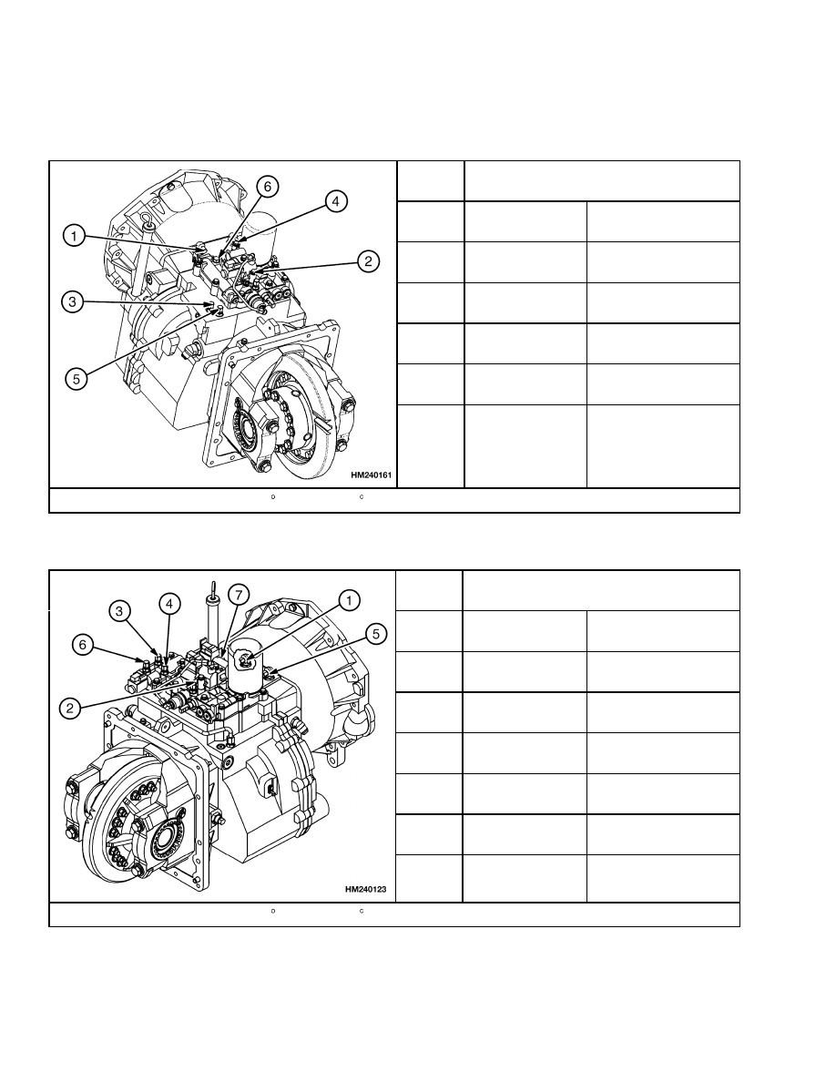
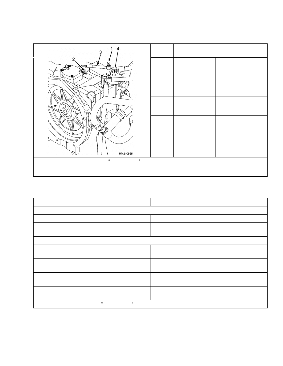
Transmission Oil Pressures
Table 1. Single-Speed
Port
No.
Transmission Pressures*
1
Transmission
Pump
1310 to 1476 kPa
(190 to 214 psi)
2
Reverse Clutch
862 to 1048 kPa
(125 to 152 psi)
3
Forward Clutch
862 to 1048 kPa
(125 to 152 psi)
4
Torque
Converter
765 to 903 kPa
(111 to 131 psi)
5
Lubrication
Circuit
61 to 111 kPa
(9 to 16 psi)
6
Modulator
Pressure Variation
*Oil temperature at least 50 to 65 C (120 to 150 F) and engine speed at 2000 rpm.
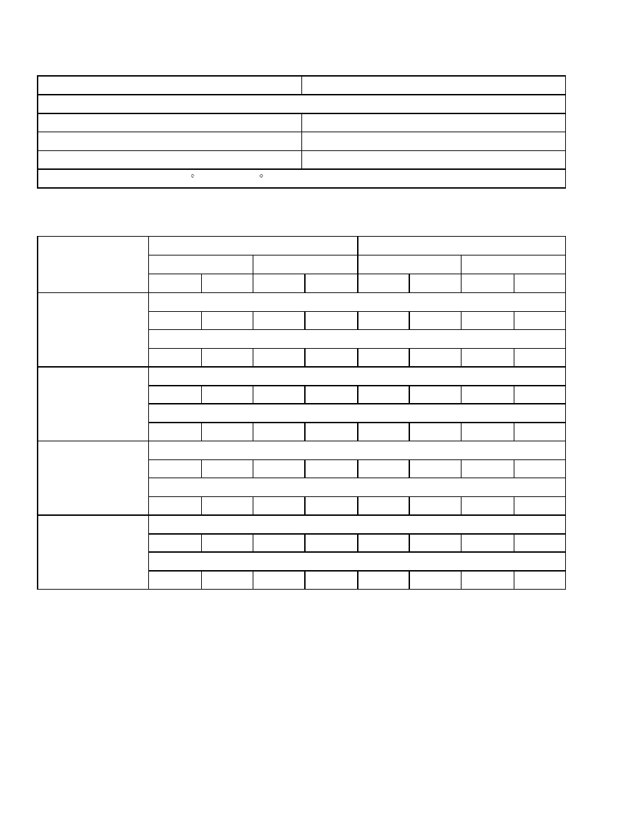
Table 2. Two-Speed
Port
No.
Transmission Pressures*
1
Transmission
Pump
1310 to 1476 kPa
(190 to 214 psi)
2
Reverse Clutch
862 to 1048 kPa
(125 to 152 psi)
3
Forward-Low
Clutch
862 to 1048 kPa
(125 to 152 psi)
4
Forward-High
Clutch
862 to 1048 kPa
(125 to 152 psi)
5
Torque Converter
765 to 903 kPa
(111 to 131 psi)
6
Lubrication
Circuit
61 to 111 kPa
(9 to 16 psi)
7
Modulator
Pressure Variation
*Oil temperature at least 50 to 65 C (120 to 150 F) and engine speed at 2000 rpm.
4
8000 SRM 738
Hydraulic System
Table 3. Hydrostatic Transmission
Port
No.
Transmission Pressures*
1
Charge
16 to 17 bar
(230 to 240 psi)
@2200 RPM
2
Pilot Supply
41 to 48 bar
(600 to 700 psi)
@2200 RPM
3
Forward Loop
M
B
460 to 480 bar
(6670 to 6960 psi)
@2200 RPM
4
Reverse Loop M
A
460 to 480 bar
(6670 to 6960 psi)
@2200 RPM
*Oil temperature at least 50 to 65 C (120 to 150 F) and engine speed at 2000 rpm.
If using Translink
®
, see the section Hydrostatic Transmission, Troubleshooting and Repairs 1300
SRM 801.
Hydraulic System
Item
Specification
Hydraulic Pump*
Type
Gear
Priority Flow (Steering)
17 to 19 liter/min (4.5 to 5.0 gal/min) at 9.6 MPa
(1400 psi) and 800 engine rpm
Hydraulic Pump*
Hydraulic Pump Flow to Main Control Valve
H3.50-4.00XMS (H70-90XM)
116 liter/min (30.6 gal/min) @ 2200 rpm No Load
Hydraulic Pump Flow to Main Control Valve
H3.50-4.00XMS (H70-90XM)
112 liter/min (29.6 gal/min) @ 2200 rpm Rated Load
Hydraulic Pump Flow to Main Control Valve
H4.50-5.50XMS (H100-120XM)
125 liter/min (33.0 gal/min) @ 2200 rpm No Load
Hydraulic Pump Flow to Main Control Valve
H4.50-5.50XMS (H100-120XM)
121 liter/min (32.0 gal/min) @ 2200 rpm Rated Load
*Pressures with oil at 50 to 80 C (120 to 180 F).
5
Torque Specifications
8000 SRM 738
Item
Specification
Relief Pressures*
Steering Circuit
10.7 MPa (1550 psi)
Tilt and Auxiliary Circuit
15.5 MPa (2250 psi)
Lift Circuit
22.0 MPa (3200 psi)
*Pressures with oil at 50 to 80 C (120 to 180 F).
Mast Speeds
Lifting
Lowering
No Load
Rated Load
No Load
Rated Load
Unit
m/sec
ft/min
m/sec
ft/min
m/sec
ft/min
m/sec
ft/min
Two-Stage Mast
0.63
124
0.57
112
0.47
93
0.55
108
Three-Stage Mast
H3.50-4.00XM
(H70-90XMS)
GM V-6 Engine
0.59
116
0.54
106
0.51
100
0.52
102
Two-Stage Mast
0.66
130
0.60
118
0.47
93
0.56
110
Three-Stage Mast
H3.50-4.00XMS
(H70-90XM)
Perkins Engine
0.59
116
0.55
108
0.51
100
0.52
102
Two-Stage Mast
0.50
98
0.49
96
0.42
83
0.50
98
Three-Stage Mast
H4.00-5.50XM
(H100-120XM)
GM V-6 Engine
0.48
94
0.47
93
0.40
79
0.47
93
Two-Stage Mast
0.49
96
0.42
83
0.42
83
0.50
98
Three-Stage Mast
H4.00-5.50XM
(H100-120XM)
Perkins Engine
0.47
93
0.40
79
0.40
79
0.47
93
Torque Specifications
BRAKE SYSTEM
Backplate Nuts
340 to 375 N•m (251 to 277 lbf ft)
DIFFERENTIAL
Ring Gear Bolts
140 N•m (103 lbf ft)
Differential Case Half Capscrews
140 N•m (103 lbf ft)
Differential Bearing Caps
225 N•m (166 lbf ft)
Thrust Bolt Lock Nut
75 to 95 N•m (55 to 70 lbf ft)
6

8000 SRM 738
Torque Specifications
Adjustment Nut Retainers
19 N•m (14 lbf ft)
Pinion Nut (Output Gear)
1100 N•m (811 lbf ft)
DRIVE AXLE
Drive Axle Hangers to Frame Bolts
320 to 350 N•m (236 to 258 lbf ft)
Axle Shaft Capscrews
225 to 250 N•m (166 to 184 lbf ft)
Wheel Bearing Adjustment Nut
200 to 225 N•m (148 to 166 lbf ft) Initial
34 N•m (25 lbf ft) Final
Wheel Bearing Lock Nut
135 to 150 N•m (100 to 110 lbf ft)
Wheel Nuts
610 to 680 N•m (450 to 502 lbf ft)
ENGINE, GM V-6 4.3 LITER
Alternator Pulley
61 N•m (45 lbf ft)
Balance Shaft Gear Capscrew
20 N•m (15 lbf ft) Plus 35 Degrees
Balance Shaft Retainer Capscrews
14 N•m (10 lbf ft)
Camshaft Retainer Capscrews
14 N•m (10 lbf ft)
Camshaft Sprocket Capscrews
28 N•m (21 lbf ft)
Camshaft Sprocket Nut
28 N•m (21 lbf ft)
Connecting Rod Cap See Engine Manual
Coolant Pump to Engine Block
40 N•m (30 lbf ft)
Cooling Fan to Pulley
24 N•m (18 lbf ft)
Cylinder Head See Engine Manual
Distributor Mount Capscrew
34 N•m (25 lbf ft)
Exhaust Manifold
Center Two Bolts: 36 N•m (27 lbf ft)
All Other Bolts: 28 N•m (21 lbf ft)
Flywheel
80 N•m (59 lbf ft)
Flywheel Housing
48 N•m (35 lbf ft)
Inlet Manifold to Cylinder Head
48 N•m (35 lbf ft)
Main Bearing Cap
106 N•m (78 lbf ft)
Oil Pump Cover
14 N•m (10 lbf ft)
Oil Pump to Crankcase
30 N•m (22 lbf ft)
Oil Pressure Switch
27 N•m (20 lbf ft)
Oil Screen Support to Crankcase
50 N•m (37 lbf ft)
Oil Sump to Crankcase
25 N•m (18 lbf ft)
Rear Oil Seal Retainer Screws and Nuts
15 N•m (11 lbf ft)
Rocker Arm Cover
10 N•m (7 lbf ft)
Rocker Arm Nuts
25 N•m (18 lbf ft)
Rocker Arm Studs
47 N•m (35 lbf ft)
Thermostat Housing
25 N•m (18 lbf ft)
Timing Cover
27 N•m (20 lbf ft)
Valve Lifter Retainer Bolts
16 N•m (12 lbf ft)
Vibration Damper
95 N•m (70 lbf ft)
7

Torque Specifications
8000 SRM 738
ENGINE, PERKINS 1004-42
Camshaft Gear Capscrew
95 N•m (70 lbf ft)
Connecting Rod Capscrews
155 N•m (114 lbf ft)
Connecting Rod Nuts
125 N•m (92 lbf ft)
Crankshaft Pulley
115 N•m (85 lbf ft)
Cylinder Head See Engine Manual
Damper on Crankshaft Pulley
75 N•m (55 lbf ft)
Exhaust Manifold Nuts
44 N•m (32 lbf ft)
Flywheel Capscrews
105 N•m (77 lbf ft)
Flywheel Housing Capscrews
75 N•m (55 lbf ft)
Fuel Injection Pump Gear
28 N•m (21 lbf ft)
Fuel Injection Pump Mount
22 N•m (16 lbf ft)
Idler Gear Capscrews
44 N•m (32 lbf ft)
Intake Manifold Capscrews
44 N•m (32 lbf ft)
Main Bearing Capscrews
265 N•m (195 lbf ft)
Oil Pump
22 N•m (16 lbf ft)
Oil Pump Cover
28 N•m (21 lbf ft)
Oil Pump to Bearing Cap
22 N•m (16 lbf ft)
Rear Oil Seal Housing
22 N•m (16 lbf ft)
Rocker Arm Brackets, Aluminum
40 N•m (30 lbf ft)
Rocker Arm Brackets, Cast Iron
75 N•m (55 lbf ft)
Timing Case Capscrews - M8
22 N•m (16 lbf ft)
Timing Case Capscrews - M10
44 N•m (32 lbf ft)
Timing Case Cover
22 N•m (16 lbf ft)
Valve Cover
44 N•m (32 lbf ft)
FRAME
Counterweight Capscrews
555 N•m (409 lbf ft)
Engine Mount Nuts
165 N•m (122 lbf ft)
Overhead Capscrews
90 N•m (66 lbf ft)
Radiator Support Capscrews, Outer
66 N•m (49 lbf ft)
Radiator Support Capscrews, Inner
38 N•m (28 lbf ft)
LIFT CYLINDERS
Main Lift Cylinder Retainer Cap
340 to 410 N•m (251 to 302 lbf ft)
Free-Lift Cylinder Retainer Cap
400 to 475 N•m (295 to 350 lbf ft)
Free-Lift Cylinder Mount Capscrews
121 N•m (89 lbf ft)
MAIN CONTROL VALVE
Through Bolt Nuts (5/16 in.)
19 N•m (14 lbf ft)
Through Bolt Nuts (3/8 in.)
45 N•m (33 lbf ft)
MASTS
Pivot Pin Capscrews
550 N•m (406 lbf ft)
Sideshift Carriage (Internal)
Lower Hook Capscrews 78 N•m (58 lbf ft)
8

8000 SRM 738
Torque Specifications
POWERSHIFT TRANSMISSION
Control Valve Capscrews
19 N•m (14 lbf ft)
Front Cover Capscrews
38 N•m (28 lbf ft)
Oil Pump Capscrews
38 N•m (28 lbf ft)
Torque Converter Housing Capscrews
38 N•m (28 lbf ft)
Torque Converter Housing to Flywheel
Housing Capscrews
38 N•m (28 lbf ft)
Torque Converter Drive Plate Capscrews
38 N•m (28 lbf ft)
Transmission to Drive Axle Capscrews
66 N•m (50 lbf ft)
STEERING SYSTEM
Axle Mount Capscrews
72 to 80 N•m (53 to 59 lbf ft)
Bearing Cap for Spindle
45 to 50 N•m (33 to 37 lbf ft)
Steering Cylinder Mount Capscrews
245 to 270 N•m (181 to 199 lbf ft)
Wheel Bearings
200 N•m (148 lbf ft) Initial
34 N•m (25 lbf ft) Final
Wheel Nuts
610 to 680 N•m (450 to 502 lbf ft)
TILT CYLINDERS
Piston Nut
400 to 440 N•m (295 to 325 lbf ft)
Retainer
400 to 500 N•m (295 to 369 lbf ft)
Rod End Lock Capscrews
66 to 73 N•m (49 to 54 lbf ft)
HYDROSTATIC COMPONENTS
Axle Valve Socket Head Capscrew
52 to 57 N•m (38 to 42 lbf ft)
Left Axle Hangar Bolts
320 to 350 N•m (236 to 258 lbf ft)
Pump Mounting Screw
320 N•m (236 lbf ft)
Pump Mounting Front Bracket To Axle
38 N•m (28 lbf ft)
Pump Mounting Front Bracket To Pump
66 N•m (49 lbf ft)
Coupler Hub
90 N•m (66 lbf ft)
Plastic Adapter To Flywheel Drive Plate
52 N•m (38 lbf ft)
Loop Tube To Hose
136 N•m (100 lbf ft)
Loop Tube To Pump
110 N•m (81 lbf ft)
Loop Tube To Clamp
38 N•m (28 lbf ft)
Loop Hose To Axle
71 N•m (52 lbf ft)
Left Axle Hanger Pins
555 to 610 N•m (409 to 450 lbf ft)
Pump Valve Capscrews
8 N•m (70 lbf in)
Charge Pump Socket Head Capscrews
24 N•m (212 lbf in)
9

NOTES
____________________________________________________________
____________________________________________________________
____________________________________________________________
____________________________________________________________
____________________________________________________________
____________________________________________________________
____________________________________________________________
____________________________________________________________
____________________________________________________________
____________________________________________________________
____________________________________________________________
____________________________________________________________
____________________________________________________________
____________________________________________________________
____________________________________________________________
____________________________________________________________
____________________________________________________________
____________________________________________________________
____________________________________________________________
____________________________________________________________
10


TECHNICAL PUBLICATIONS
8000 SRM 738
5/04 (9/03)(1/03)(8/02)(8/01)(8/99) Printed in United Kingdom
Document Outline
- toc
- tables
Wyszukiwarka
Podobne podstrony:
1553986 8000SRM1083 (05 2004) UK EN
1554635 8000SRM1079 (06 2004) UK EN
897506 4000SRM0521 (05 2004) UK EN
897067 1400SRM0285 (05 2004) UK EN
1565454 8000SRM1113 (06 2004) UK EN
1554636 8000SRM1080 (11 2004) UK EN
910460 1600SRM0258 (05 2004) UK EN
1456997 8000SRM0708 (10 2004) UK EN
1580526 8000SRM1151 (05 2005) UK EN
897390 0100SRM0449 (05 2004) UK EN
1598591 8000SRM1208 (05 2005) UK EN
910442 8000SRM0231 (12 2004) UK EN
897104 0100SRM0322 (05 2004) UK EN
1554635 8000SRM1079 (06 2004) UK EN
897506 4000SRM0521 (05 2004) UK EN
więcej podobnych podstron