CAPACITIES AND
SPECIFICATIONS
E1.50-2.00XM (E25-35Z) [E114];
E2.00XMS (E40ZS) [E114]
PART NO. 1565454
8000 SRM 1113

SAFETY PRECAUTIONS
MAINTENANCE AND REPAIR
• When lifting parts or assemblies, make sure all slings, chains, or cables are correctly
fastened, and that the load being lifted is balanced. Make sure the crane, cables, and
chains have the capacity to support the weight of the load.
• Do not lift heavy parts by hand, use a lifting mechanism.
• Wear safety glasses.
• DISCONNECT THE BATTERY CONNECTOR before doing any maintenance or repair
on electric lift trucks. Disconnect the battery ground cable on internal combustion lift
trucks.
• Always use correct blocks to prevent the unit from rolling or falling. See HOW TO PUT
THE LIFT TRUCK ON BLOCKS in the Operating Manual or the Periodic Mainte-
nance section.
• Keep the unit clean and the working area clean and orderly.
• Use the correct tools for the job.
• Keep the tools clean and in good condition.
• Always use HYSTER APPROVED parts when making repairs. Replacement parts
must meet or exceed the specifications of the original equipment manufacturer.
• Make sure all nuts, bolts, snap rings, and other fastening devices are removed before
using force to remove parts.
• Always fasten a DO NOT OPERATE tag to the controls of the unit when making repairs,
or if the unit needs repairs.
• Be sure to follow the WARNING and CAUTION notes in the instructions.
• Gasoline, Liquid Petroleum Gas (LPG), Compressed Natural Gas (CNG), and Diesel fuel
are flammable. Be sure to follow the necessary safety precautions when handling these
fuels and when working on these fuel systems.
• Batteries generate flammable gas when they are being charged. Keep fire and sparks
away from the area. Make sure the area is well ventilated.
NOTE: The following symbols and words indicate safety information in this
manual:
WARNING
Indicates a condition that can cause immediate death or injury!
CAUTION
Indicates a condition that can cause property damage!

Capacities and Specifications
Table of Contents
TABLE OF CONTENTS
Wheels and Tires................................................................................................................................................
Counterweights ..................................................................................................................................................
Hydraulic System...............................................................................................................................................
Capacities ...........................................................................................................................................................
Battery Specifications........................................................................................................................................
Battery Height Specifications (Hoods and Battery Types)..........................................................................
Maximum Carriage and Tilt Creep Rates ........................................................................................................
Mast Speeds .......................................................................................................................................................
E25-35Z, E40ZS Mast Speeds (36 and 48 Volt) Americas ...........................................................................
E1.50-2.00XM Mast Speeds (48 Volt) Europe ..............................................................................................
Torque Specifications .........................................................................................................................................
Frame .............................................................................................................................................................
Mast................................................................................................................................................................
Drive Axle, Speed Reducer, and Differential ...............................................................................................
Steering Axle..................................................................................................................................................
Brake ..............................................................................................................................................................
Adhesives and Sealants .....................................................................................................................................
This section is for the following models:
E1.50-2.00XM (E25-35Z) [E114];
E2.00XMS (E40ZS) [E114]
©2004 HYSTER COMPANY
i

"THE
QUALITY
KEEPERS"
HYSTER
APPROVED
PARTS

8000 SRM 1113
Counterweights
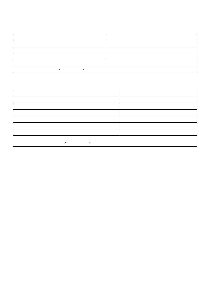
Wheels and Tires
Item
Specification
Torque Value of Drive Wheel Bolts
330 N•m (243 lbf ft)
Torque Value of Steer Wheel Nuts (Pneumatic)
155 N•m (114 lbf ft)
Torque Value of Spindle Nut for Steer Wheels
68 N•m (50 lbf ft), loosen, then
3 N•m (2 lbf ft)
Size of Standard Drive Tires
18 × 5 × 12-1/8*
Size of Optional Drive Tires
18 × 5 × 12-1/8*
Size of Standard Steer Tires
14 × 4-1/2 × 8*
Size of Optional Steer Tires
15 × 5 × 11-1/4*
*Electric Compound Tires are available in smooth or lug tread. Polyurethane and nonmarking compounds
are only available on smooth tread. NEVER mix types of tread or tire compound on the same truck.
Counterweights
Model
Weight
+30 kg (66 lb)
0 kg (0 lb)
E25Z
337 kg (743 lb)
E1.50XM, (E30Z)
514 kg (1133 lb)
E1.75XM (E35Z)
626 kg (1380 lb)
E2.00XMS (E40ZS)
739 kg (1629 lb)
1
Capacities
8000 SRM 1113
Hydraulic System
Item
Specification
Relief Pressure, Lift System
17.9 ±0.7 MPa (2600 ±100 psi)
Relief Pressure, Tilt System
15.75 ±0.7 MPa (2250 ±100 psi)
Relief Pressure, Auxiliary
15.75 ±0.7 MPa (2250 ±100 psi)
Relief Pressure, Steering System
5709 ±248 kPa (828 ±36 psi)
*Oil temperature 54 to 66 C (130 to 150 F).
Capacities
Item
Specification
Hydraulic System (Full Mark On Dipstick)*
11.3 liter (3.0 gal)
Differential/Speed Reducer
2.9 liter (3.1 qt)
Brake Fluid
0.24 liter (0.5 pt)
Hydraulic Pump Capacities**
Large Lift Pump
19 cc/rev. (1.16 in
3
/rev.)
Steering Pump
4.23 cc/rev. (0.26 in
3
/rev.)
*Check after all air is removed from the system and with the mast fully lowered.
**Oil temperature at 54 to 66 C (130 to 150 F).
2
8000 SRM 1113
Battery Specifications
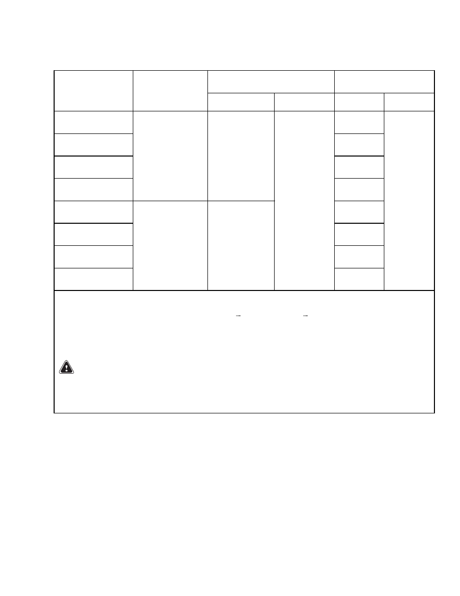
Battery Specifications
Battery Size Minimum/
Maximum*
Weight
Model
Min.
Compartment
Size
Length × Width
Length
Width
Minimum
Maximum
E25Z
794 kg
(1750 lb)
E1.50XM
(E30Z)
839 kg
(1850 lb)
E1.75XM
(E35Z)
839 kg
(1850 lb)
E2.00XM
(E40ZS)
695 × 879 mm
(27.4 × 34.6 in.)
784/876 mm
(30.9/34.5 in.)
839 kg
(1850 lb)
E25Z
794 kg
(1750 lb)
E1.50XM
(E30Z)
839 kg
(1850 lb)
E1.75XM
(E35Z)
839 kg
(1850 lb)
E2.00XM
(E40ZS)
695 × 909 mm
(27.4 × 35.8 in.)
784/907 mm
(30.9/35.7 in.)
654/692 mm
(25.8/27.2 in.)
839 kg
(1850 lb)
1132 kg
(2496 lb)
617 mm (24.3 in.) = maximum height for all batteries. This dimension is 31.75 mm (1.25 in.) less with
optional battery rollers.
Tolerances of the battery compartment are +3 and
0 mm (+0.12 and
0 in.). The battery size column
shows the size range that will permit the battery to still fit into a battery compartment.
Battery compartment length is front to back. Width is side to side. The length dimension of the battery
must fit within the battery compartment side-to-side dimension with a clearance of 0 to 13 mm (0 to 0.5 in.)
maximum. Battery width must fit within the battery compartment front-to-back dimension.
WARNING
The battery must fit the battery compartment so that the battery restraint system will operate
correctly. Use only batteries with the correct length shown in this table. Adjust the spacer plate
and side spacers to prevent the battery from moving more than 13 mm (0.5 in.) forward or back-
ward.
3
Battery Specifications
8000 SRM 1113
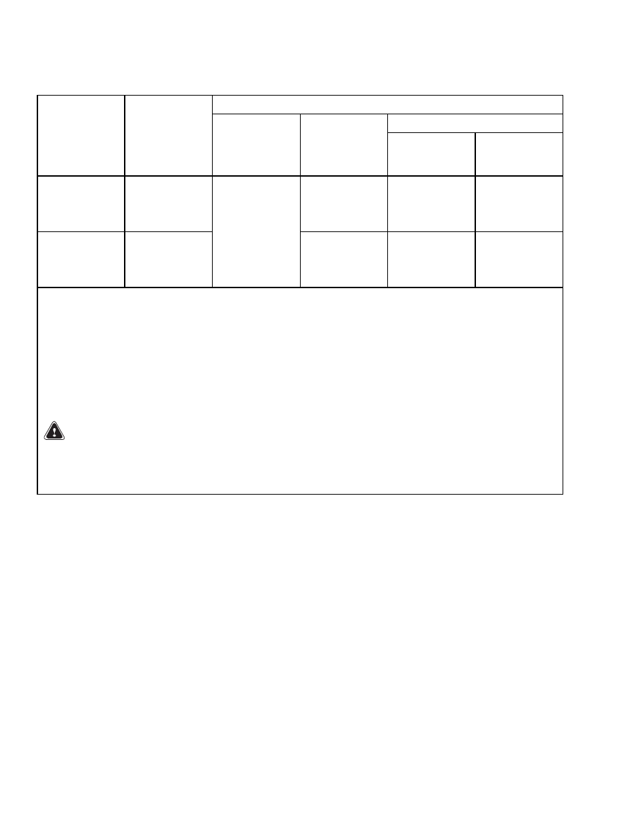
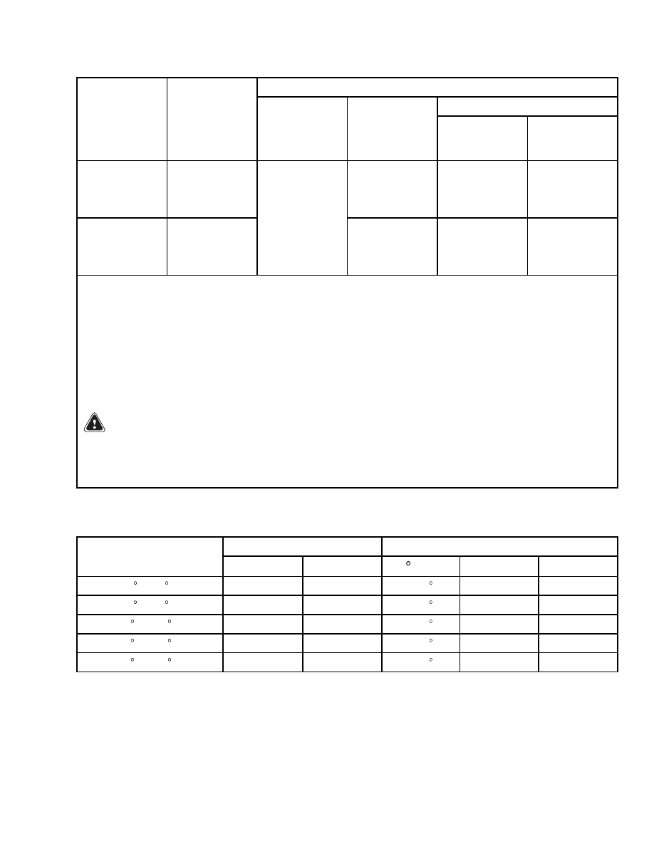
BATTERY HEIGHT SPECIFICATIONS (HOODS AND BATTERY TYPES)
Maximum Height - Standard Hood
Cell Connectors and Terminals
Model
Battery Type
With Battery
Tray*
With Cell
Cap**
Electrically
Insulated***
Not
Electrically
Insulated**
E1.50-1.75XM
(E25-35Z),
E2.00XMS
(E40ZS)
I
594 mm
(23.4 in.)
594 mm
(23.4 in.)
574 mm
(22.6 in.)
E1.50-1.75XM
(E25-35Z)),
E2.00XMS
(E40ZS)
II, III
607 mm
(23.9 in.)
NA
NA
NA
NA = Not Applicable
BATTERY TYPES
TYPE I - Battery without a cover as part of the battery.
TYPE II - Battery with a cover that is flat and is fastened to case of battery. Cover opens from FRONT
OR REAR when installed in lift truck.
TYPE III - Battery with a cover that is flat and is fastened to case of battery. Cover opens from SIDE
when installed in lift truck.
*Battery Types II and III bottom of battery to highest point (top of cover or top of hinge).
**Minimum height below top of battery tray is 4 mm (0.16 in.).
***Minimum height below top of battery tray is 0.5 mm (0.02 in.).
WARNING
The battery must fit the battery compartment so that the battery restraint system will operate
correctly. Use only batteries with the correct length shown in the table above. Adjust the spacer
plate and side spacers to prevent the battery from moving more than 13 mm (0.5 in.) forward,
backward, or to the side.
4
8000 SRM 1113
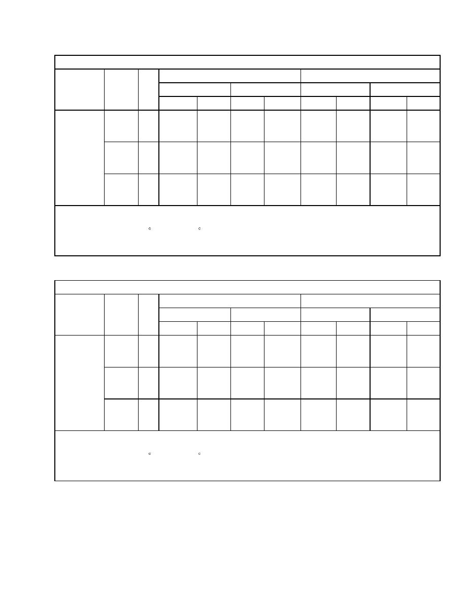
Maximum Carriage and Tilt Creep Rates
Maximum Height - Raised Hood
Cell Connectors and Terminals
Model
Battery Type
With Battery
Tray*
With Cell
Cap**
Electrically
Insulated***
Not
Electrically
Insulated**
E1.50-1.75XM
(E25-35Z)),
E2.00XMS
(E40ZS)
I
625 mm
(24.6 in.)
627 mm
(24.7 in.)
607 mm
(23.9 in.)
E1.50-1.75XM
(E25-35Z)),
E2.00XMS
(E40ZS)
II, III
640 mm
(25.2 in.)
NA
NA
NA
NA = Not Applicable
BATTERY TYPES
TYPE I - Battery without a cover as part of the battery.
TYPE II - Battery with a cover that is flat and is fastened to case of battery. Cover opens from FRONT
OR REAR when installed in lift truck.
TYPE III - Battery with a cover that is flat and is fastened to case of battery. Cover opens from SIDE
when installed in lift truck.
*Battery Types II and III bottom of battery to highest point (top of cover or top of hinge).
**Minimum height below top of battery tray is 4 mm (0.16 in.).
***Minimum height below top of battery tray is 0.5 mm (0.02 in.).
WARNING
The battery must fit the battery compartment so that the battery restraint system will operate
correctly. Use only batteries with the correct length shown in the table above. Adjust the spacer
plate and side spacers to prevent the battery from moving more than 13 mm (0.5 in.) forward,
backward, or to the side.
Maximum Carriage and Tilt Creep Rates
Vertical Creep at Carriage
Tilt Creep at Cylinder Rod
Hydraulic Oil
Temperature
mm/Min
in./Min
/Min
mm/Min
in./Min
20 C (68 F)
2.2 mm
0.09 in.
0.10
0.63 mm
0.03 in.
30 C (86 F)
3.3 mm
0.13 in.
0.15
0.95 mm
0.04 in.
40 C (104 F)
6.3 mm
0.25 in.
0.29
1.83 mm
0.07 in.
50 C (122 F)
10.0 mm
0.39 in.
0.47
2.97 mm
0.12 in.
60 C (140 F)
14.6 mm
0.57 in.
0.68
4.30 mm
0.17 in.
5

Mast Speeds
8000 SRM 1113
Mast Speeds
E25-35Z, E40ZS MAST SPEEDS (36 AND 48 VOLT) AMERICAS
AC or DC Motor and 19 cc (1.16 in.
3
) Lift Pump*
Lifting
Lowering
Rated Load
No Load
Rated Load
No Load
Model
Mast
V
m/sec
ft/min
m/sec
ft/min
m/sec
ft/min
m/sec
ft/min
Two-
Stage
LFL
36
48
0.396
0.508
78
100
0.544
0.681
107
134
0.508
100
0.472
93
Two-
Stage
FFL
36
48
0.396
0.508
78
100
0.538
0.671
106
132
0.462
91
0.371
73
E25Z
Three-
Stage
FFL
36
48
0.386
0.498
76
98
0.518
0.650
102
128
0.478
94
0.411
81
Two-
Stage
LFL
36
48
0.381
0.488
75
96
0.544
0.681
107
134
0.508
100
0.472
93
Two-
Stage
FFL
36
48
0.376
0.483
74
95
0.538
0.671
106
132
0.462
91
0.371
73
E30Z
Three-
Stage
FFL
36
48
0.366
0.478
72
94
0.518
0.650
102
128
0.478
94
0.411
81
Two-
Stage
LFL
36
48
0.361
0.467
71
92
0.544
0.681
107
134
0.508
100
0.472
93
Two-
Stage
FFL
36
48
0.356
0.467
70
92
0.538
0.671
106
132
0.462
91
0.371
73
E35Z
Three-
Stage
FFL
36
48
0.351
0.457
69
90
0.518
0.650
102
128
0.478
94
0.411
81
LFL = Limited Free Lift
FFL = Full Free Lift
*Oil temperature 54 to 66 C (130 to 150 F). Lifting speeds (valve fully open) ±10% acceptable. No Load
lowering speeds are minimum values. Rated Load lowering speeds are maximum values. Load center is
610 mm (24 in.).
6
8000 SRM 1113
Mast Speeds
AC or DC Motor and 19 cc (1.16 in.
3
) Lift Pump*
Lifting
Lowering
Rated Load
No Load
Rated Load
No Load
Model
Mast
V
m/sec
ft/min
m/sec
ft/min
m/sec
ft/min
m/sec
ft/min
Two-
Stage
LFL
36
48
0.340
0.447
67
88
0.544
0.681
107
134
0.508
100
0.472
93
Two-
Stage
FFL
36
48
0.335
0.447
66
88
0.538
0.671
106
132
0.462
91
0.371
73
E40ZS
Three-
Stage
FFL
36
48
0.330
0.437
65
86
0.518
0.650
102
128
0.478
94
0.411
81
LFL = Limited Free Lift
FFL = Full Free Lift
*Oil temperature 54 to 66 C (130 to 150 F). Lifting speeds (valve fully open) ±10% acceptable. No Load
lowering speeds are minimum values. Rated Load lowering speeds are maximum values. Load center is
610 mm (24 in.).
E1.50-2.00XM MAST SPEEDS (48 VOLT) EUROPE
AC or DC Motor and 19 cc (1.16 in.
3
) Lift Pump*
Lifting
Lowering
Rated Load
No Load
Rated Load
No Load
Model
Mast
V
m/sec
ft/min
m/sec
ft/min
m/sec
ft/min
m/sec
ft/min
Two-
Stage
LFL
48
0.478
94
0.681
134
0.508
100
0.472
93
Two-
Stage
FFL
48
0.478
94
0.671
132
0.462
91
0.371
73
E1.50XM
Three-
Stage
FFL
48
0.467
92
0.650
128
0.478
94
0.411
81
LFL = Limited Free Lift
FFL = Full Free Lift
*Oil temperature 54 to 66 C (130 to 150 F). Lifting speeds (valve fully open) ±10% acceptable. No Load
lowering speeds are minimum values. Rated Load lowering speeds are maximum values. Load center is
500 mm (19.7 in.).
7

Torque Specifications
8000 SRM 1113
AC or DC Motor and 19 cc (1.16 in.
3
) Lift Pump*
Lifting
Lowering
Rated Load
No Load
Rated Load
No Load
Model
Mast
V
m/sec
ft/min
m/sec
ft/min
m/sec
ft/min
m/sec
ft/min
Two-
Stage
LFL
48
0.452
89
0.681
134
0.508
100
0.472
93
Two-
Stage
FFL
48
0.452
89
0.671
132
0.462
91
0.371
73
E1.75XM
Three-
Stage
FFL
48
0.442
87
0.650
128
0.478
94
0.411
81
Two-
Stage
LFL
48
0.432
85
0.681
134
0.508
100
0.472
93
Two-
Stage
FFL
48
0.432
85
0.671
132
0.462
91
0.371
73
E2.00XMS
Three-
Stage
FFL
48
0.422
83
0.650
128
0.478
94
0.411
81
LFL = Limited Free Lift
FFL = Full Free Lift
*Oil temperature 54 to 66 C (130 to 150 F). Lifting speeds (valve fully open) ±10% acceptable. No Load
lowering speeds are minimum values. Rated Load lowering speeds are maximum values. Load center is
500 mm (19.7 in.).
Torque Specifications
FRAME
Overhead Guard
Front leg M12 x 1.75 x 40 or 50 capscrews
66 N•m (49 lbf ft)
Rear leg M12 x 1.75 x 60 capscrews with
nuts 72 N•m (53 lbf ft)
Counterweight Capscrews
upper 380 N•m (260 lbf ft)
lower (tow pin area) 66 N•m (50 lbf ft)
Traction Motor to Speed Reducer Housing
M12 × 1.75 × 35 hex head screws (7)
71 to 83 N•m (52 to 61 lbf ft)
MAST
Capscrews for Mast Assembly Mounts
at Drive Axle
90 N•m (66 lbf ft)
Capscrews for Sideshift Carriage Mount
435 N•m (320 lbf ft)
Bolts for Lift Cylinder Mounts
53 N•m (39 lbf ft)
Nuts for Lowering Control Valve
18 N•m (13 lbf ft)
Setscrews for Chain Sheave
8 N•m (71 lbf in)
8

8000 SRM 1113
Torque Specifications
Nuts for Free-Lift Cylinder Brackets
38 N•m (28 lbf ft)
Bolts for Free-Lift Cylinder Brackets
53 N•m (39 lbf ft)
Capscrew for Free-Lift Cylinder Hose Sheave
41 N•m (30 lbf ft)
Capscrews for Chain Guards on
Crosshead Assembly
66 N•m (49 lbf ft)
Capscrews for Hose Guards on Crosshead
Assembly
66 N•m (49 lbf ft)
Capscrews for Stub Shaft
53 N•m (39 lbf ft)
Capscrews for Hose Brackets and Clamps
8 N•m (71 lbf in)
Capscrews for Hose Guides at Lower
Crossmember
33 N•m (24 lbf ft)
Nut for Piston Rod on Tilt Cylinder
163 to 190 N•m (120 to 140 lbf ft)
Retainer for Piston and Rod Assembly
on Tilt Cylinder
163 to 176 N•m (120 to 130 lbf ft)
DRIVE AXLE, SPEED REDUCER, AND
DIFFERENTIAL
Capscrews for Axle Trunnion Caps
71 to 83 N•m (52 to 61 lbf ft)
Traction Motor Mount Capscrews
71 to 83 N•m (52 to 61 lbf ft)
Speed Reducer Support Capscrews
216 N•m (159 lbf ft)
Speed Reducer-to-Axle Capscrews
41 to 49 N•m (30 to 36 lbf ft)
Speed Reducer Cover Capscrews
21 to 25 N•m (15 to 18 lbf ft)
Pinion Lock Nut (Rotating Torque)
5.4 to 5.9 N•m (4 to 4.6 lbf ft)
Differential Bearing Nuts (Rotating Torque)
2.9 to 3.4 N•m (2.2 to 2.5 lbf ft)
Bearing Cap Capscrews 263 to 315 N•m
(194 to 233 lbf ft)
Ring Gear Capscrews
152 to 167 N•m (112 to 123 lbf ft)
Mount Bolts for Brake Assembly (Back Plate)
152 to 167 N•m (112 to 123 lbf ft)
Hub Castle Nuts
Initial: 200 N•m (148 lbf ft) while rotating hub
Final: 3.4 N•m (30 lbf in)
Wheel Bolts
330 N•m (244 lbf ft)
STEERING AXLE
Plate Bolts of Rubber Mounts
41 to 49 N•m (30 to 36 lbf ft)
Mount Bolts of Steering Cylinder
41 to 49 N•m (30 to 36 lbf ft)
Wheel Castle Nut
Initial: 68 N•m (50 lbf ft) while rotating
wheel. Loosen, then
3 N•m (2 lbf ft)
Wheel Nut (Pneumatic)
155 N•m (114 lbf ft)
Cylinder Guides
117.7 ±15 N•m (86.8 ±11 lbf ft)
BRAKE
Back Plate to Axle Mount Bolts
152 to 167 N•m (112 to 123 lbf ft)
Seat Brake
Brake Assembly Capscrew (at Motor
Armature) 66 N•m (49 lbf ft)
Pivot Nut for Brake Lever 40 N•m (30 lbf ft)
9

Adhesives and Sealants
8000 SRM 1113
Adhesives and Sealants
Hyster Part
No.
Loctite
®
Part No.
Description
Size
360387
222
Small Screw Threadlock (Purple)
50 ml (1.7 oz)
318702*
242
Removable Threadlock (Blue)
10 ml (0.34 oz)
226414*
271
High Strength Threadlock (Red)
10 ml (0.34 oz)
318996
277
High Viscosity Threadlock (Red)
50 ml (1.7 oz)
318650
290
Low Viscosity Threadlock (Green)
0.6 ml (0.02 oz)
251099
290
Low Viscosity Threadlock (Green)
50 ml (1.7 oz)
355844*
422
SuperBonder
®
Adhesive
3 ml (0.1 oz)
350830
515
Gasket Eliminator (Purple)
6 ml (0.2 oz)
313022*
515
Gasket Eliminator (Purple)
50 ml (1.7 oz)
273338*
567
Pipe Sealant with Teflon
®
(White)
50 ml (1.7 oz)
318705
595
Super Flex
®
Silicone
100 ml (3.4 oz)
318701
609
Retaining Compound
10 ml (0.34 oz)
341959
680
Retaining Compound
50 ml (1.7 oz)
226415
Primer T - Aerosol
177 ml (6 oz)
316865
Antiseize Compound
476 ml (16 oz)
360053
Chisel Gasket Remover (10 Aerosol cans per case)
536 ml (18 oz)
318700*
Adhesive & Sealant Kit (Contains one each of * items)
Loctite
®
, Super Flex
®
, and SuperBonder
®
are registered trademarks of the Loctite Corporation.
Teflon
®
is a registered trademark of Du Pont de Nemours Co. Inc.
10


TECHNICAL PUBLICATIONS
8000 SRM 1113
6/04 Printed in United Kingdom
Document Outline
- toc
Wyszukiwarka
Podobne podstrony:
1554635 8000SRM1079 (06 2004) UK EN
1554635 8000SRM1079 (06 2004) UK EN
1510478 8000SRM0988 (06 2005) UK EN
1554636 8000SRM1080 (11 2004) UK EN
1554632 2000SRM1086 (06 2004) UK EN
1456997 8000SRM0708 (10 2004) UK EN
1467764 8000SRM0738 (05 2004) UK EN
897494 1900SRM0513 (06 2004) UK EN
1554626 0100SRM1073 (06 2004) UK EN
1554630 1900SRM1077 (06 2004) UK EN
897559 0100SRM0545 (06 2004) UK EN
1553986 8000SRM1083 (05 2004) UK EN
897880 1400SRM0618 (06 2004) UK EN
897881 1600SRM0619 (06 2004) UK EN
910442 8000SRM0231 (12 2004) UK EN
1510478 8000SRM0988 (06 2005) UK EN
więcej podobnych podstron