CAPACITIES AND
SPECIFICATIONS
V30ZMD [D210];
E2.00-3.20XM (E45-65Z) [G108]
PART NO. 1553986
8000 SRM 1083

SAFETY PRECAUTIONS
MAINTENANCE AND REPAIR
• When lifting parts or assemblies, make sure all slings, chains, or cables are correctly
fastened, and that the load being lifted is balanced. Make sure the crane, cables, and
chains have the capacity to support the weight of the load.
• Do not lift heavy parts by hand, use a lifting mechanism.
• Wear safety glasses.
• DISCONNECT THE BATTERY CONNECTOR before doing any maintenance or repair
on electric lift trucks. Disconnect the battery ground cable on internal combustion lift
trucks.
• Always use correct blocks to prevent the unit from rolling or falling. See HOW TO PUT
THE LIFT TRUCK ON BLOCKS in the Operating Manual or the Periodic Mainte-
nance section.
• Keep the unit clean and the working area clean and orderly.
• Use the correct tools for the job.
• Keep the tools clean and in good condition.
• Always use HYSTER APPROVED parts when making repairs. Replacement parts
must meet or exceed the specifications of the original equipment manufacturer.
• Make sure all nuts, bolts, snap rings, and other fastening devices are removed before
using force to remove parts.
• Always fasten a DO NOT OPERATE tag to the controls of the unit when making repairs,
or if the unit needs repairs.
• Be sure to follow the WARNING and CAUTION notes in the instructions.
• Gasoline, Liquid Petroleum Gas (LPG), Compressed Natural Gas (CNG), and Diesel fuel
are flammable. Be sure to follow the necessary safety precautions when handling these
fuels and when working on these fuel systems.
• Batteries generate flammable gas when they are being charged. Keep fire and sparks
away from the area. Make sure the area is well ventilated.
NOTE:
The following symbols and words indicate safety information in this
manual:
WARNING
Indicates a condition that can cause immediate death or injury!
CAUTION
Indicates a condition that can cause property damage!

Capacities and Specifications
Table of Contents
TABLE OF CONTENTS
Counterweights ..................................................................................................................................................
Hydraulic System...............................................................................................................................................
Wheels and Tires................................................................................................................................................
Battery Specifications........................................................................................................................................
E2.00-3.20XM (E45-65Z, V30ZMD) ..............................................................................................................
Capacities ...........................................................................................................................................................
Movement Rates (Maximum) for Tilt Cylinders ..............................................................................................
Mast Speeds .......................................................................................................................................................
E45-65Z, and V30ZMD Mast Speeds (36 or 48 Volt) Americas ...................................................................
E2.00-3.20XM Mast Speeds (72 or 80 Volt) Europe .....................................................................................
E2.00-3.20XM Mast Speeds (72 or 80 Volt) Europe .....................................................................................
Torque Specifications .........................................................................................................................................
Frame .............................................................................................................................................................
Drive Axle, Speed Reducer, and Differential E.200-3.20XM (E45-65Z and V30ZMD) ..............................
Steering Axle E2.00-3.20XM (E45-65Z and V30ZMD) ................................................................................
Masts ..............................................................................................................................................................
Seat Brake......................................................................................................................................................
Adhesives and Sealants .....................................................................................................................................
This section is for the following models:
V30ZMD [D210];
E2.00-3.20XM (E45-65Z) [G108]
©2004 HYSTER COMPANY
i

"THE
QUALITY
KEEPERS"
HYSTER
APPROVED
PARTS
8000 SRM 1083
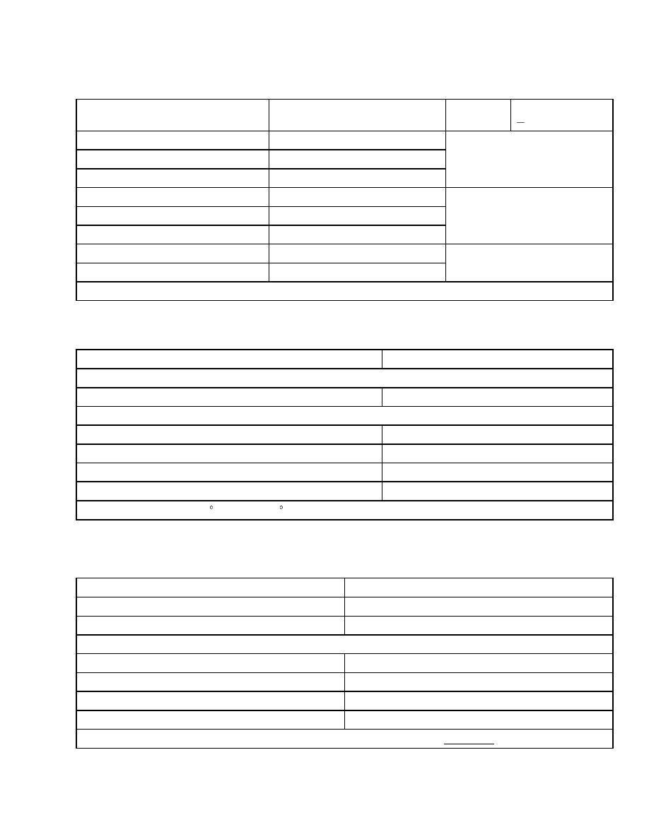
Wheels and Tires
Counterweights
Model
* mm (* in.)
Weight
+ 50 kg (110 lb)
0 kg (0 lb)
E2.00XM and E2.50XM
700 mm (27.6 in.)
E2.50XM (E50Z)
847 mm (33.3 in.)
E3.00XM
1015 mm (40.0 in.)
544 kg (1200 lb)
E45Z
700 mm (27.6 in.)
E55Z and E2.50XM (E65Z), E3.00XM
847 mm (33.3 in.)
E3.20XM and V30ZMD
1015 mm (40.0 in.)
770 kg (1700 lb)
E50Z and E2.50XM
700 mm (27.6 in.)
E60Z and E3.00XM
847 mm (33.3 in.)
976 kg (2152 lb)
*Approximate battery compartment lengths (identifies frame size).
Hydraulic System
Item
Specification
Relief Pressure, Lift System
E2.00-3.20XM (E45-65Z) and V30ZMD
21.7 ±0.7 MPa (3100 ±100 psi)
Relief Pressure, Tilt System
With Auxiliary Relief Valve
15.75 ±0.7 MPa (2250 ±100 psi)
Without Auxiliary Relief Valve
21.7 ±0.7 MPa (3100 ±100 psi)
Relief Pressure, Auxiliary
15.75 ±0.7 MPa (2250 ±100 psi)
Relief Pressure, Steering System
8620 ±248 kPa (1250 ±36 psi)
*Oil temperature 54 to 66 C (130 to 150 F).
Wheels and Tires
Item
Specification
Torque - Wheel Nuts, Drive Tires
237 to 305 N•m (175 to 225 lbf ft)
Torque - Wheel Nuts, Steering Tires
34 N•m (25 lbf ft)
E2.00-3.00XM (E45-65Z and V30ZMD)
Drive Tires, Size Standard
21 × 7 × 15*
Drive Tires, Size Optional
21 × 8 × 15*
Steering Tires, Size Standard
16 × 5 × 10.5*
Steering Tires, Size Optional
16 × 6 × 10.5*
*Smooth, lug tread; standard and nonmarking, electric compound and for all models, smooth polyurethane.
1
Battery Specifications
8000 SRM 1083
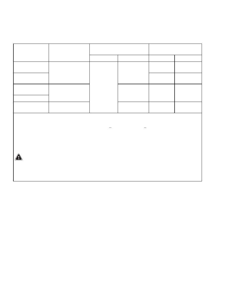
Battery Specifications
E2.00-3.20XM (E45-65Z, V30ZMD)
Battery Size Minimum/
Maximum
Weight
Model
Minimum
Compartment Size
Length × Width
Length
Width
Minimum
Maximum
E2.00XM,
E2.50XM
985 kg
(2172 lb)
1453 kg
(3203 lb)
E45-50Z
695 × 987 mm
(27.4 × 38.8 in.)
681/691 mm
(26.8/27.2 in.)
1044 kg
(2302 lb)
1498 kg
(3302 lb)
E2.50XM,
E3.00XM
(E45-60Z)
842 × 987 mm
(33.1 × 38.8 in.)
800/838 mm
(31.5/33.0 in.)
1317 kg
(2903 lb)
1771 kg
(3904 lb)
E3.00-3.20XM
(E65Z)(V30ZMD)
1010 × 987 mm
(39.8 × 38.8 in.)
978/983 mm
(38.5/38.7 in.)
1001/1006 mm
(39.4/39.6 in.)
1553 kg
(3424 lb)
1998 kg
(4405 lb)
612 mm (24.1 in.) = maximum height for batteries with a cover.
579 mm (22.8 in.) = maximum height for batteries without a cover.
The tolerances of the battery compartment are +3 and
0 mm (+0.118 and
0 in.). The battery size column
shows the size range that will permit the battery to still fit into a battery compartment.
The battery compartment length is front to back. Width is side to side. The length dimension of the battery
must fit within the battery compartment side-to-side dimension with a clearance of 0 to 13 mm (0 to 0.5 in.)
maximum. Battery width must fit within the battery compartment front-to-back dimension.
WARNING
The battery must fit the battery compartment so that the battery restraint system will operate
correctly. Use only batteries with the correct length shown in this table. Adjust the spacer plate
and side spacers to prevent the battery from moving more than 13 mm (0.5 in.) forward or back-
ward.
2
8000 SRM 1083
Movement Rates (Maximum) for Tilt Cylinders
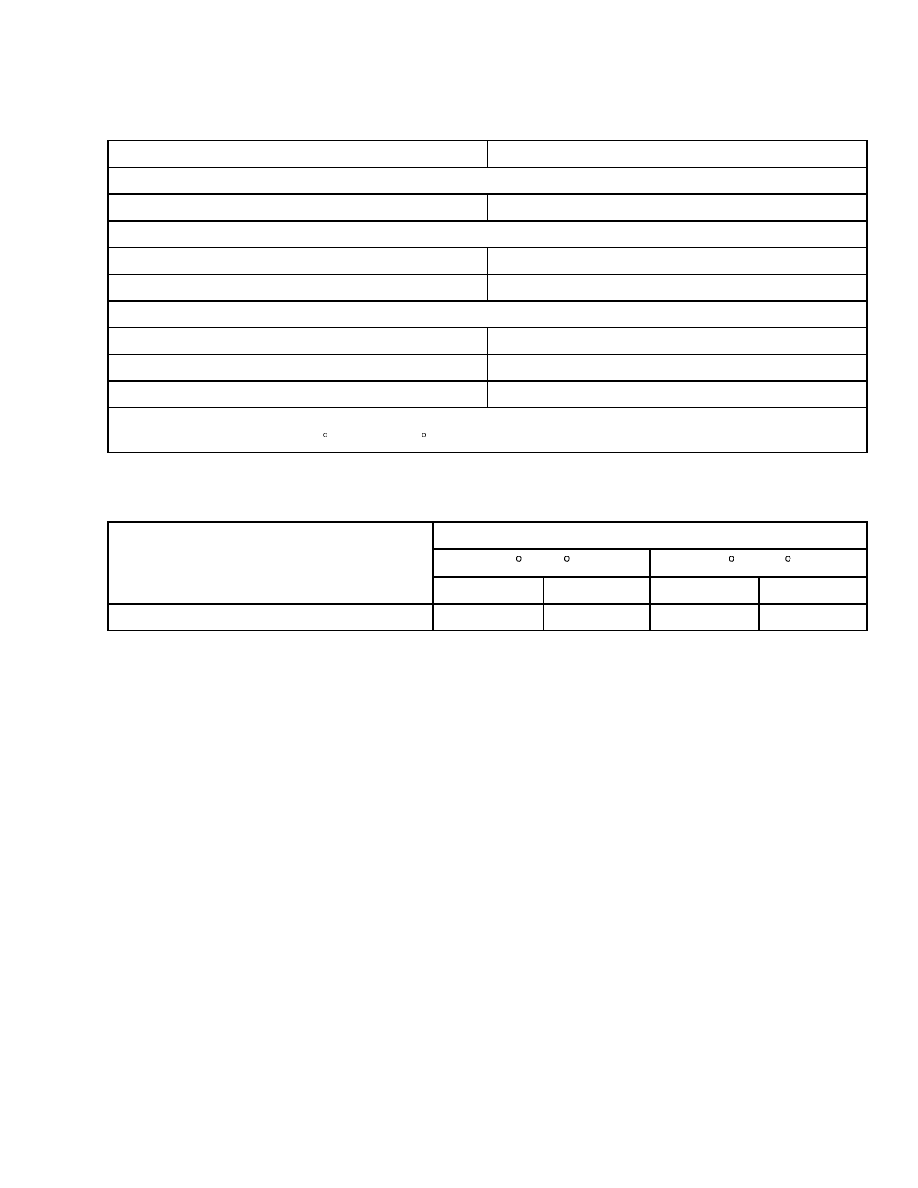
Capacities
Item
Specification
Hydraulic System (Full Mark on Dipstick)*
E2.00-3.20XM (E45-65Z and V30ZMD)
23.0 liter (6.1 gal)
Differential/Speed Reducer
E2.00-3.20XM (E45-65Z and V30ZMD)
4.2 liter (8.8 pt)
Brake Fluid
0.24 liter (0.5 pt)
Hydraulic Pump Capacities**
Large Lift Pump
19 cc/rev. (1.16 in.
3
/rev.)
Small Lift Pumps
12 cc/rev. (0.73 in.
3
/rev.)
Steering Pump
4.23 cc/rev. (0.26 in.
3
/rev.)
*Check after all air is removed from the system and with the mast fully lowered.
**Oil temperature at 54 to 66 C (130 to 150 F)
Movement Rates (Maximum) for Tilt Cylinders
Hydraulic Oil Temperature/Mast Tilt Rate
20 C (68 F)
60 C (140 F)
Lift Truck Model
mm/min
in/min
mm/min
in/min
All Models (Except V30ZMD)
0.8
0.03
5.0
0.20
3

Mast Speeds
8000 SRM 1083
Mast Speeds
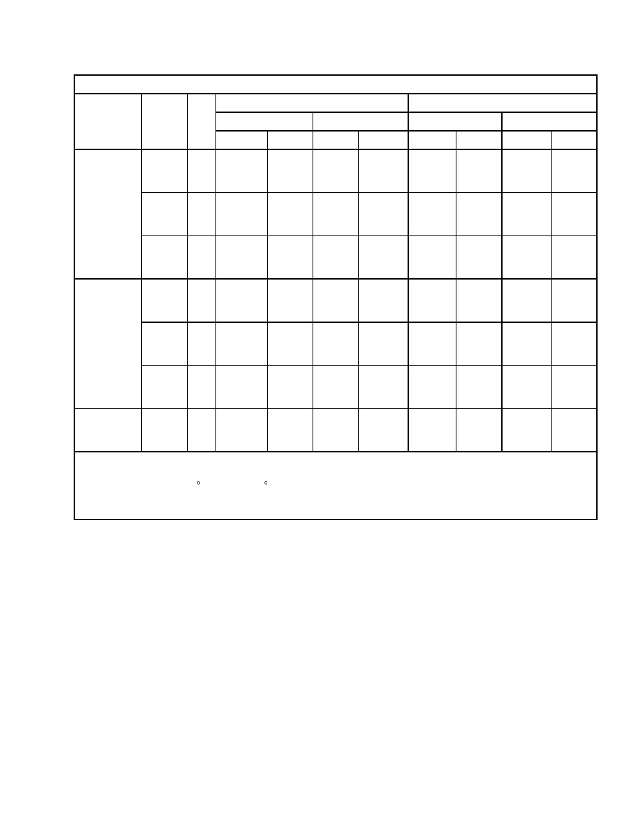
E45-65Z, AND V30ZMD MAST SPEEDS (36 OR 48 VOLT) AMERICAS
AC or DC Motor
Lifting
Lowering
Rated Load
No Load
Rated Load
No Load
Model
Mast
V
m/sec
ft/min
m/sec
ft/min
m/sec
ft/min
m/sec
ft/min
Two-
Stage
LFL
36
48
0.295
0.396
58
78
0.513
0.625
101
123
0.569
112
0.508
100
Two-
Stage
FFL
36
48
0.305
0.396
60
78
0.472
0.625
93
123
0.523
103
0.457
90
Three-
Stage
FFL
36
48
0.295
0.396
58
78
0.462
0.610
91
120
0.538
106
0.467
92
E45Z
Four-
Stage
FFL
36
48
0.290
0.401
57
79
0.452
0.569
89
112
0.447
88
0.411
81
Two-
Stage
LFL
36
48
0.284
0.376
56
74
0.513
0.625
101
123
0.574
113
0.508
100
Two-
Stage
FFL
36
48
0.295
0.381
58
75
0.472
0.625
93
123
0.538
106
0.457
90
Three-
Stage
FFL
36
48
0.290
0.381
57
75
0.462
0.610
91
120
0.549
108
0.467
92
E50Z
Four-
Stage
FFL
36
48
0.279
0.381
55
75
0.452
0.610
89
112
0.447
88
0.411
81
Two-
Stage
LFL
36
48
0.274
0.361
54
71
0.513
0.625
101
123
0.584
115
0.508
100
Two-
Stage
FFL
36
48
0.284
0.371
56
73
0.472
0.625
93
123
0.554
109
0.457
90
E55Z
Three-
Stage
FFL
36
48
0.279
0.371
55
73
0.462
0.610
91
120
0.559
110
0.467
92
LFL = Limited Free Lift
FFL = Full Free Lift
Oil temperature 54 to 66 C (130 to 150 F). Lifting speeds (valve fully open) ±10% acceptable. No Load
lowering speeds are minimum values. Rated Load lowering speeds are maximum values.
N/A = Not Available.
4
8000 SRM 1083
Mast Speeds
AC or DC Motor
Lifting
Lowering
Rated Load
No Load
Rated Load
No Load
Model
Mast
V
m/sec
ft/min
m/sec
ft/min
m/sec
ft/min
m/sec
ft/min
Two-
Stage
LFL
36
48
0.249
0.325
49
64
0.472
0.589
93
116
0.569
112
0.457
90
Two-
Stage
FFL
36
48
0.249
0.330
49
65
0.472
0.625
93
123
0.538
106
0.366
72
E60Z
Three-
Stage
FFL
36
48
0.249
0.330
49
65
0.462
0.610
91
120
0.544
107
0.396
78
Two-
Stage
LFL
36
48
0.239
0.315
47
62
0.472
0.589
93
116
0.559
110
0.457
90
Two-
Stage
FFL
36
48
0.244
0.320
48
63
0.472
0.625
93
123
0.523
103
0.366
72
E65Z
Three-
Stage
FFL
36
48
0.244
0.320
48
63
0.462
0.610
91
120
0.533
105
0.396
78
V30ZMD
Three-
Stage
FFL
36
48
N/A
N/A
N/A
N/A
N/A
N/A
N/A
N/A
0.462
91
0.462
91
LFL = Limited Free Lift
FFL = Full Free Lift
Oil temperature 54 to 66 C (130 to 150 F). Lifting speeds (valve fully open) ±10% acceptable. No Load
lowering speeds are minimum values. Rated Load lowering speeds are maximum values.
N/A = Not Available.
5
Mast Speeds
8000 SRM 1083
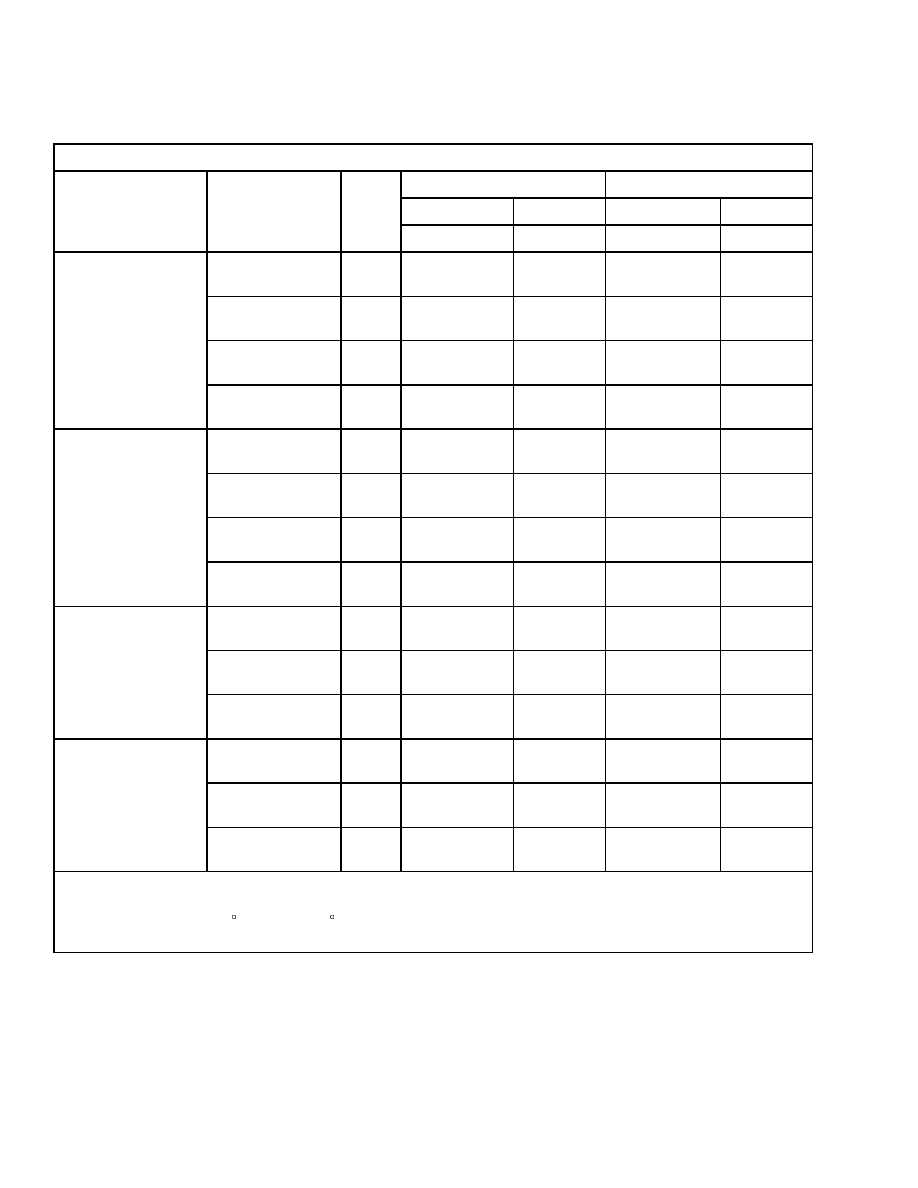
E2.00-3.20XM MAST SPEEDS (72 OR 80 VOLT) EUROPE
Contactor Controlled DC Motor
Lifting
Lowering
Rated Load
No Load
Rated Load
No Load
Model
Mast
V
m/sec
m/sec
m/sec
m/sec
Two-Stage LFL
72
80
0.376
0.422
0.544
0.605
0.559
0.508
Two-Stage FFL
72
80
0.396
0.442
0.569
0.635
0.508
0.457
Three-Stage FFL
72
80
0.386
0.432
0.559
0.625
0.528
0.467
E2.00XM
Four-Stage FFL
72
80
0.330
0.366
0.483
0.538
0.447
0.411
Two-Stage LFL
72
80
0.345
0.391
0.544
0.605
0.574
0.508
Two-Stage FFL
72
80
0.366
0.411
0.569
0.635
0.538
0.457
Three-Stage FFL
72
80
0.356
0.401
0.559
0.625
0.549
0.467
E2.50XM
Four-Stage FFL
72
80
0.315
0.351
0.483
0.538
0.447
0.411
Two-Stage LFL
72
80
0.300
0.335
0.488
0.544
0.569
0.457
Two-Stage FFL
72
80
0.310
0.345
0.503
0.564
0.538
0.366
E3.00XM
Three-Stage FFL
72
80
0.310
0.345
0.503
0.559
0.544
0.396
Two-Stage LFL
72
80
0.295
0.330
0.488
0.544
0.559
0.457
Two-Stage FFL
72
80
0.300
0.335
0.503
0.564
0.523
0.366
E3.20XM
Three-Stage FFL
72
80
0.300
0.335
0.503
0.559
0.533
0.396
LFL = Limited Free Lift
FFL = Full Free Lift
Oil temperature 54 to 66 C (130 to 150 F). Lifting speeds (valve fully open) ±10% acceptable. No Load
lowering speeds are minimum values. Rated Load lowering speeds are maximum values.
6
8000 SRM 1083
Mast Speeds
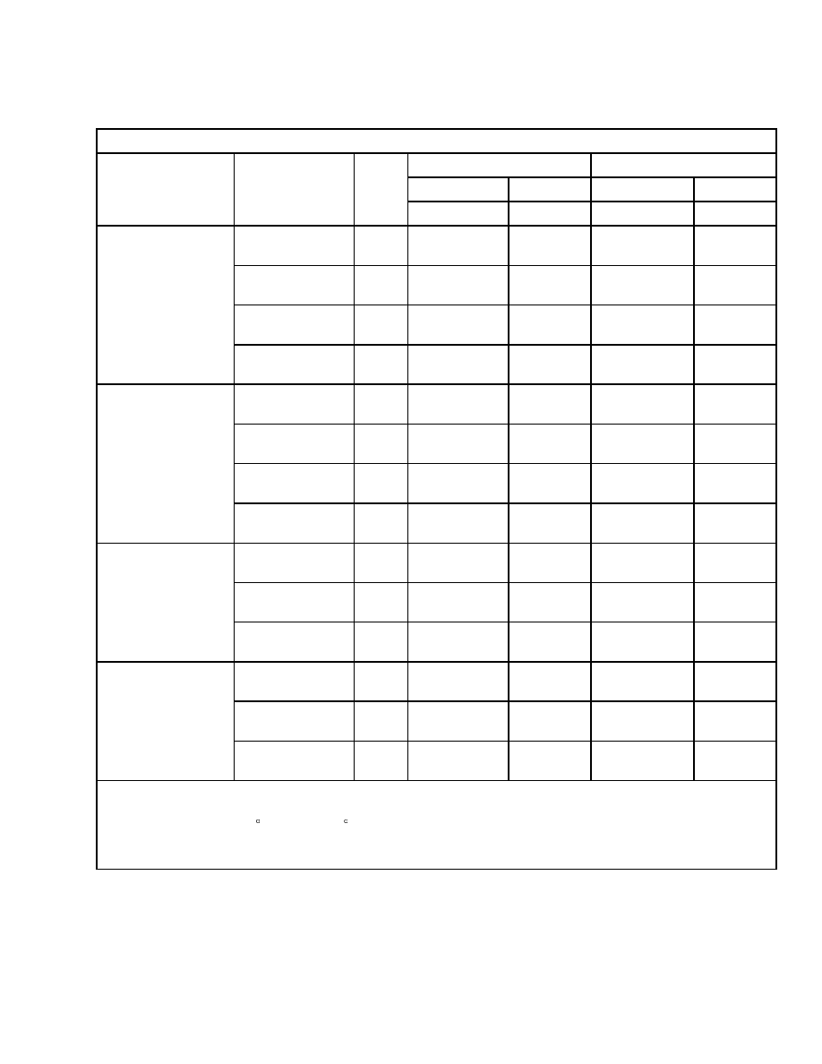
E2.00-3.20XM MAST SPEEDS (72 OR 80 VOLT) EUROPE
AC Motor
Lifting
Lowering
Rated Load
No Load
Rated Load
No Load
Model
Mast
V
m/sec
m/sec
m/sec
m/sec
Two-Stage LFL
72
80
0.396
0.444
0.544
0.605
0.559
0.508
Two-Stage FFL
72
80
0.417
0.465
0.569
0.635
0.508
0.457
Three-Stage FFL
72
80
0.406
0.455
0.559
0.625
0.528
0.467
E2.00XM
Four-Stage FFL
72
80
0.347
0.384
0.483
0.538
0.447
0.411
Two-Stage LFL
72
80
0.363
0.411
0.544
0.605
0.574
0.508
Two-Stage FFL
72
80
0.385
0.433
0.569
0.635
0.538
0.457
Three-Stage FFL
72
80
0.375
0.422
0.559
0.625
0.549
0.467
E2.50XM
Four-Stage FFL
72
80
0.331
0.369
0.483
0.538
0.447
0.411
Two-Stage LFL
72
80
0.316
0.353
0.488
0.544
0.569
0.457
Two-Stage FFL
72
80
0.326
0.363
0.503
0.564
0.538
0.366
E3.00XM
Three-Stage FFL
72
80
0.326
0.363
0.503
0.559
0.544
0.396
Two-Stage LFL
72
80
0.311
0.348
0.488
0.544
0.559
0.457
Two-Stage FFL
72
80
0.316
0.353
0.503
0.564
0.523
0.366
E3.20XM
Three-Stage FFL
72
80
0.316
0.353
0.503
0.559
0.533
0.396
LFL = Limited Free Lift
FFL = Full Free Lift
Oil temperature 54 to 66 C (130 to 150 F). Lifting speeds (valve fully open) ±10% acceptable. No Load
lowering speeds are minimum values. Rated Load lowering speeds are maximum values.
N/A = Not Available.
7

Torque Specifications
8000 SRM 1083
Torque Specifications
FRAME
Overhead Guard - Front Leg M12 × 1.75 × 50
Capscrews (3) Standard Torque Value
Overhead Guard - Rear Leg M12 × 1.75 × 50
Capscrews (2) Standard Torque Value
Counterweight Capscrews - Upper
Capscrews (2)
E2.00-3.20XM (E45-65Z) 380 N•m (280 lbf ft)
Counterweight Capscrews - Lower (tow pin)
M12 × 1.75 × 90 Capscrews (2)
66 N•m (49 lbf ft)
Counterweight Capscrews - Cover
3/8 UNC × 1-1/4 Capscrews (2)
52 N•m (38 lbf ft)
DRIVE AXLE, SPEED REDUCER, AND
DIFFERENTIAL E.200-3.20XM (E45-65Z
AND V30ZMD)
Wheel Nuts
237 to 305 N•m (175 to 225 lbf ft)
Wheel Lock Nut
205 N•m (151 lbf ft) Initial
34 N•m (25 lbf ft) Final
Axle Housing (differential) to Spindle Housing
(axle) M12 × 1.75 × 35 Capscrews (16 each side)
90 N•m (66 lbf ft)
Axle Flange M12 × 1.75 × 35 Capscrews
(16 ea. axle)
90 N•m (66 lbf ft)
Axle Hangers to Frame
Torque wrench on Head of Bolt 780 N•m
(575 lbf ft)
Torque wrench on Nut of Bolt 715 N•m (527 lbf ft)
Back Plate to Axle Mount Capscrews (8)
255 N•m (188 lbf ft)
Wheel Cylinder M8 × 1.25 Capscrews
18 to 27 N•m (13 to 20 lbf ft)
Ring Gear to Differential Case
7/16 UNF × 1 bolts (12)
111 N•m (82 lbf ft)
Differential Case Halves 3.8 UNF ×
3-1/2 Capscrews (8)
50 N•m (37 lbf ft)
Bearing Cap Capscrews for Differen-
tial Bearings (4)
95 to 110 N•m (70 to 81 lbf ft)
Lock Plate Capscrews for Adjusting Nuts (2)
19 N•m (14 lbf ft)
Lock Nut for Thrust Screw
68 to 95 N•m (50 to 70 lbf ft)
Pinion Nut (use shims to set rotating
torque with nut tight)
340 N•m (251 lbf ft)
Speed Reducer Housing to Axle (differential)
Housing E2.00-3.20XM (E45-65Z and
V30ZMD) only
M10 x 1.5 x 30 bolts (6) 38 N•m (28 lbf ft)
M10 x 1.5 x 40 bolts (2) 38 N•m (28 lbf ft)
Traction Motor to Speed Reducer
M10 x 1.5 x 35 bolts (2) 38 N•m (28 lbf ft)
M10 x 1.5 x 70 bolts (6) 38 N•m (28 lbf ft)
STEERING AXLE E2.00-3.20XM (E45-65Z
AND V30ZMD)
Mount Brackets M12 × 1.75 × 45 bolts (4)
88 N•m (65 lbf ft)
Steering Cylinder to Axle Capscrews
M16 × 2 × 130 (4)
121 N•m (89 lbf ft)
Tie Rod Nuts 3/4 UNF (2)
163 N•m (120 lbf ft)
Capscrews, Lower Spindle Cap (6) 3/8 UNC × 1
44 N•m (32 lbf ft)
Castle Nut, Wheel Hut (2)
Initial 68 N•m (50 lbf ft)
while rotating wheel. Loosen, then
3 N•m (2 lbf ft)
8

8000 SRM 1083
Adhesives and Sealants
MASTS
Capscrews, Hanger Caps
M12 x 1.75 x 100 (4) 90 N•m (66 lbf ft)
Mast to Mount Pivot Pins 130 N•m (96 lbf ft)
Tilt Rod End M12 × 1.75 × 55 (2)
90 N•m (66 lbf ft)
SEAT BRAKE
Lever Arm Pivot at Motor M12 × 1.75 (1)
40 N•m (30 lbf ft)
Brake Drum Mount (to armature shaft)
M12 × 1.75 × 50 (1)
66 N•m (49 lbf ft) lubed
Adhesives and Sealants
Hyster Part
No.
Loctite
®
Part No.
Description
Size
360387
222
Small Screw Threadlock (Purple)
50 ml (1.7 oz)
318702*
242
Removable Threadlock (Blue)
10 ml (0.34 oz)
226414*
271
High Strength Threadlock (Red)
10 ml (0.34 oz)
318996
277
High Viscosity Threadlock (Red)
50 ml (1.7 oz)
318650
290
Low Viscosity Threadlock (Green)
0.6 ml (0.02 oz)
251099
290
Low Viscosity Threadlock (Green)
50 ml (1.7 oz)
355844*
422
SuperBonder
®
Adhesive
3 ml (0.1 oz)
350830
515
Gasket Eliminator (Purple)
6 ml (0.2 oz)
313022*
515
Gasket Eliminator (Purple)
50 ml (1.7 oz)
273338*
567
Pipe Sealant with Teflon
®
(White)
50 ml (1.7 oz)
318705
595
Super Flex
®
Silicone
100 ml (3.4 oz)
318701
609
Retaining Compound
10 ml (0.34 oz)
341959
680
Retaining Compound
50 ml (1.7 oz)
226415
Primer T - Aerosol
177 ml (6 oz)
316865
Antiseize Compound
476 ml (16 oz)
360053
Chisel Gasket Remover (10 Aerosol cans per case)
536 ml (18 oz)
318700*
Adhesive & Sealant Kit (Contains one each of * items)
Loctite
®
, Super Flex
®
, and SuperBonder
®
are registered trademarks of the Loctite Corporation.
Teflon
®
is a registered trademark of Du Pont de Nemours Co. Inc.
9

NOTES
____________________________________________________________
____________________________________________________________
____________________________________________________________
____________________________________________________________
____________________________________________________________
____________________________________________________________
____________________________________________________________
____________________________________________________________
____________________________________________________________
____________________________________________________________
____________________________________________________________
____________________________________________________________
____________________________________________________________
____________________________________________________________
____________________________________________________________
____________________________________________________________
____________________________________________________________
____________________________________________________________
____________________________________________________________
____________________________________________________________
10


TECHNICAL PUBLICATIONS
8000 SRM 1083
5/04 (3/04)(11/03) Printed in United Kingdom
Document Outline
- toc
Wyszukiwarka
Podobne podstrony:
1467764 8000SRM0738 (05 2004) UK EN
1554635 8000SRM1079 (06 2004) UK EN
897506 4000SRM0521 (05 2004) UK EN
897067 1400SRM0285 (05 2004) UK EN
1565454 8000SRM1113 (06 2004) UK EN
1554636 8000SRM1080 (11 2004) UK EN
910460 1600SRM0258 (05 2004) UK EN
1456997 8000SRM0708 (10 2004) UK EN
1580526 8000SRM1151 (05 2005) UK EN
897390 0100SRM0449 (05 2004) UK EN
1598591 8000SRM1208 (05 2005) UK EN
910442 8000SRM0231 (12 2004) UK EN
897104 0100SRM0322 (05 2004) UK EN
1554635 8000SRM1079 (06 2004) UK EN
897506 4000SRM0521 (05 2004) UK EN
więcej podobnych podstron