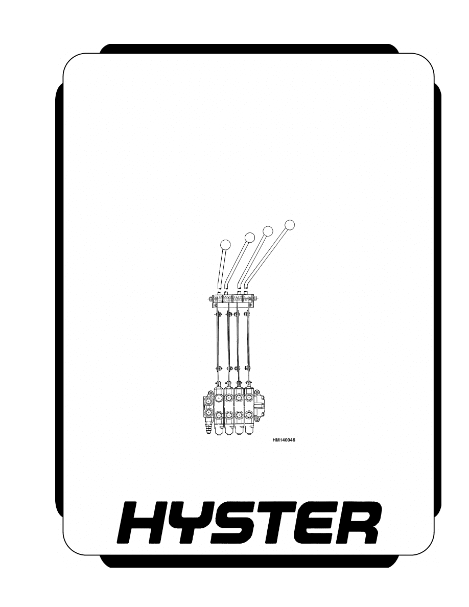
MAIN CONTROL VALVE
S/H/E1.25-1.75XL (S/H/E25-35XL);
S/H/E/J2.00-3.00XL (S/H/E/J40-60XL);
H3.50-5.00XL (H70-110XL);
S/E3.50-5.50XL (S/E70-120XL, E70-120XL
3
) [D004, C098];
E30-40CR; E3.50-5.50XL, E4.50XLS
(E70-120Z, E100ZS) [D098]
PART NO. 899782
2000 SRM 77
SAFETY PRECAUTIONS
MAINTENANCE AND REPAIR
• When lifting parts or assemblies, make sure all slings, chains, or cables are correctly
fastened, and that the load being lifted is balanced. Make sure the crane, cables, and
chains have the capacity to support the weight of the load.
• Do not lift heavy parts by hand, use a lifting mechanism.
• Wear safety glasses.
• DISCONNECT THE BATTERY CONNECTOR before doing any maintenance or repair
on electric lift trucks. Disconnect the battery ground cable on internal combustion lift
trucks.
• Always use correct blocks to prevent the unit from rolling or falling. See HOW TO PUT
THE LIFT TRUCK ON BLOCKS in the Operating Manual or the Periodic Mainte-
nance section.
• Keep the unit clean and the working area clean and orderly.
• Use the correct tools for the job.
• Keep the tools clean and in good condition.
• Always use HYSTER APPROVED parts when making repairs. Replacement parts
must meet or exceed the specifications of the original equipment manufacturer.
• Make sure all nuts, bolts, snap rings, and other fastening devices are removed before
using force to remove parts.
• Always fasten a DO NOT OPERATE tag to the controls of the unit when making repairs,
or if the unit needs repairs.
• Be sure to follow the WARNING and CAUTION notes in the instructions.
• Gasoline, Liquid Petroleum Gas (LPG), Compressed Natural Gas (CNG), and Diesel fuel
are flammable. Be sure to follow the necessary safety precautions when handling these
fuels and when working on these fuel systems.
• Batteries generate flammable gas when they are being charged. Keep fire and sparks
away from the area. Make sure the area is well ventilated.
NOTE: The following symbols and words indicate safety information in this
manual:
WARNING
Indicates a condition that can cause immediate death or injury!
CAUTION
Indicates a condition that can cause property damage!
Main Control Valve
Table of Contents
TABLE OF CONTENTS
General ...............................................................................................................................................................
Description .........................................................................................................................................................
Operation............................................................................................................................................................
Lift Section .....................................................................................................................................................
Tilt Section .....................................................................................................................................................
Tilt Backward ............................................................................................................................................
Tilt Forward...............................................................................................................................................
Relief Valve ................................................................................................................................................
Solenoid Valve for Auxiliary Function..........................................................................................................
Main Control Valve Repair ................................................................................................................................
Remove and Disassemble ..............................................................................................................................
Clean and Inspect ..........................................................................................................................................
Assemble ........................................................................................................................................................
Install .............................................................................................................................................................
Solenoid Valve for Auxiliary Function Repair..................................................................................................
Remove and Disassemble ..............................................................................................................................
Assemble and Install .....................................................................................................................................
Troubleshooting .............................................................................................................................................
Pressure Relief Valve Check and Adjustment..................................................................................................
Primary Relief Valve......................................................................................................................................
Secondary Relief Valve ..................................................................................................................................
Control Lever Arrangement and Adjustment ..................................................................................................
Specifications......................................................................................................................................................
Troubleshooting..................................................................................................................................................
This section is for the following models:
S/H/E1.25-1.75XL (S/H/E25-35XL) S/H/E/J2.00-3.00XL (S/H/E/J40-60XL)
H3.50-5.00XL (H70-110XL) S/E3.50-5.50XL (S/E70-120XL,
E70-120XL
3
) [D004, C098];
E30-40CR E3.50-5.50XL, E4.50XLS (E70-120Z, E100ZS) [D098]
©2005 HYSTER COMPANY
i

"THE
QUALITY
KEEPERS"
HYSTER
APPROVED
PARTS

2000 SRM 77
Operation
General
This section has a description and the repair procedure for the main control valve and the auxiliary solenoid
valve used in the hydraulic system.
Description
The main control valve controls the operation of the
lift, tilt, and auxiliary cylinders. The main control
valve is fastened to the cowl of the lift truck. Each
main control valve has the following sections (see
Figure 1):
• Inlet and drain section with the primary relief
valve
• Lift and lower section (with or without secondary
relief valve)
• Tilt section
• Auxiliary section
• End section
The sections are held together with three through
bolts.
Each function of the main control valve is made as a
separate section having a spool and valve body. Each
valve body casting is the same. The control spools
are different for each function.
Other sections are added to the main control valve
to control optional auxiliary functions. On some lift
trucks, a solenoid valve is used with one of these sec-
tions to give another auxiliary function.
Each spool has a spring that returns the spool to the
neutral position when the control lever is released.
Each control section has a check valve in the valve
body. The check valve and spring is held in the valve
body by the next section.
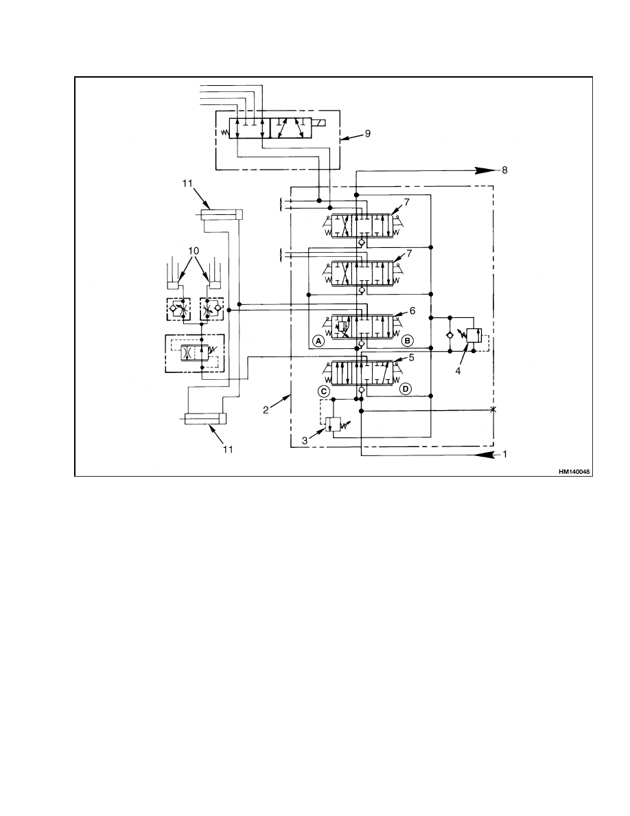
Operation
The main control valve is an open center, parallel cir-
cuit valve. See Figure 2. When open center valve
spools are in the neutral position, the hydraulic oil
flows through the valve with minimum restriction.
The oil returns through the drain passage and re-
turns to the hydraulic tank.
In a parallel circuit
valve, each spool can be operated without prevent-
ing the flow of oil to another spool.
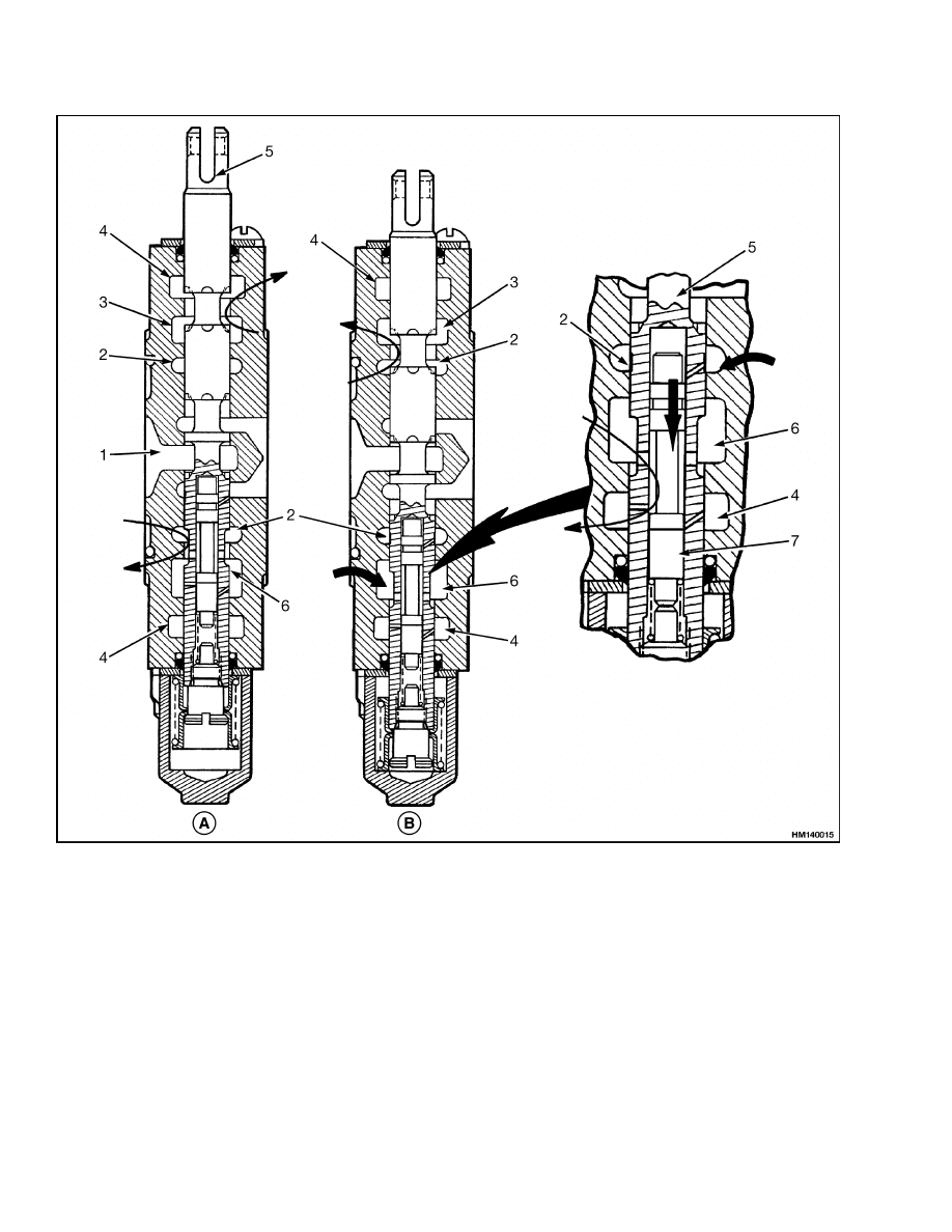
This valve has three parallel passages through the
valve. See Figure 3. When the spools are in the
neutral position, the oil flows through the open cen-
ter passage. At the end of the valve, the oil returns
through the drain passage and returns to the hy-
draulic tank. A spool makes a restriction in the open
center passage when the spool is moved from the neu-
tral position. This restriction causes an increase in
pressure in the parallel passage. The parallel pas-
sage is common to all sections of the valve, but oil
cannot flow freely through it. The increased pressure
in the parallel passage causes the oil to flow through
a check valve into a supply cavity in the valve body.
The spool gives a path from the supply cavity to the
hydraulic cylinder to do work.
LIFT SECTION
When the spool is moved to the Lift position, the spool
makes a restriction in the open center passage. See
Figure 3. The increased pressure in the parallel pas-
sage causes oil to flow through the check valve to the
supply cavity. The oil flows from the supply cavity
through a section of the spool to the lift cylinder.
When the spool is in the Lower position, the spool
opens a path from the lift cylinder to the drain cavity.
The spool is made so the oil flow through the open
center passage is not stopped.
1
Operation
2000 SRM 77
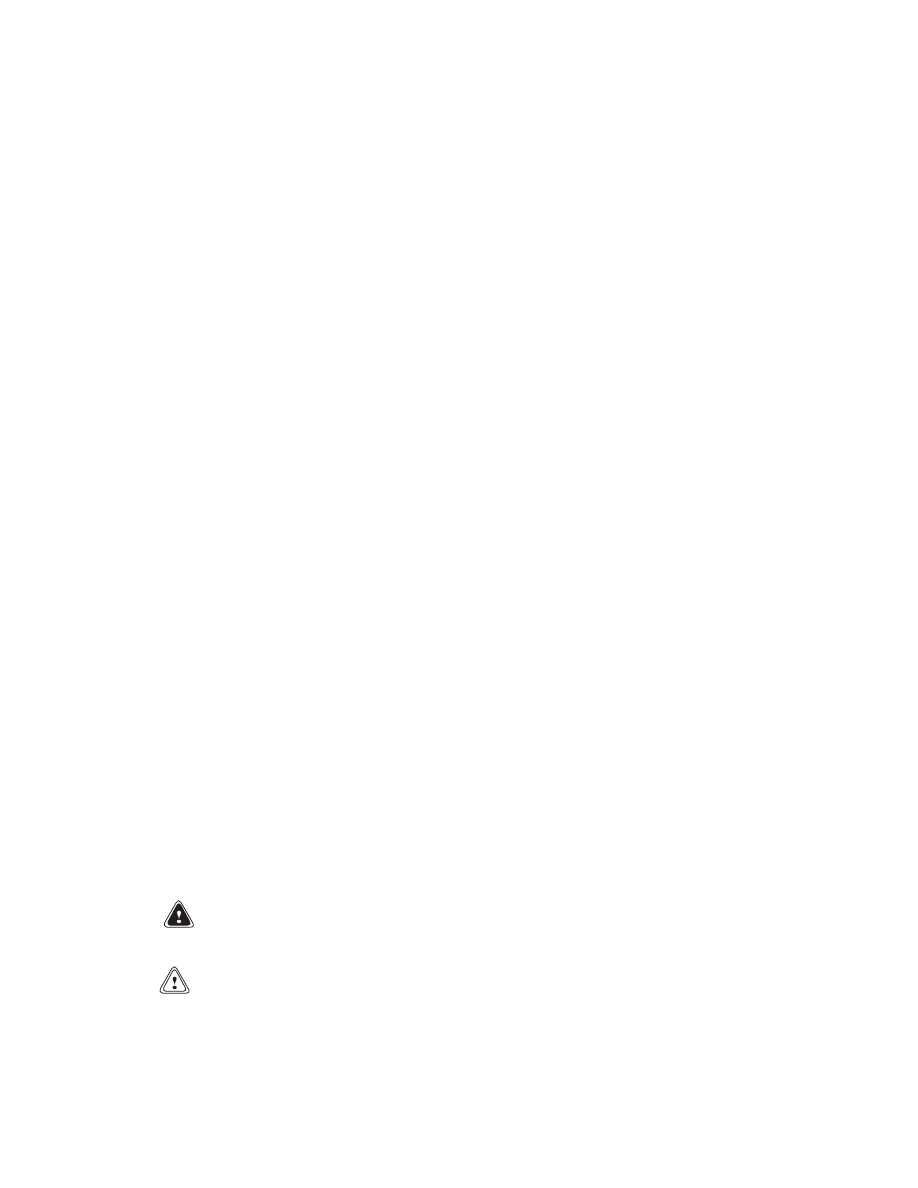
1.
INLET AND DRAIN SECTION
2.
PRESSURE RELIEF VALVE
3.
LIFT SPOOL
4.
TILT SECTION
5.
CHECK VALVE
6.
OPEN CENTER PASSAGE
7.
END CAP
8.
END COVER
9.
SUPPLY CAVITY
10. DRAIN CAVITY
11. RETURN TO HYDRAULIC TANK
12. PARALLEL PASSAGE
13. FROM HYDRAULIC PUMP
Figure 1. Main Control Valve (Typical)
2
2000 SRM 77
Operation
A. FORWARD
B. BACKWARD
C. LOWER
D. LIFT
1.
FLOW FROM HYDRAULIC PUMP
2.
MAIN CONTROL VALVE
3.
PRIMARY RELIEF VALVE
4.
SECONDARY RELIEF VALVE
5.
LIFT/LOWER SPOOL
6.
TILT SPOOL
7.
AUXILIARY SPOOL
8.
TO HYDRAULIC TANK
9.
AUXILIARY FUNCTION SOLENOID VALVE
S3.50-5.50XL (S70-120XL) ONLY
10. TO LIFT CYLINDERS
11. TILT CYLINDER
Figure 2. Control Valve Schematic
3
Operation
2000 SRM 77
A. LIFTING
B. LOWERING
1.
LIFT SPOOL
2.
CHECK VALVE
3.
OPEN CENTER PASSAGE
4.
PARALLEL PASSAGE
5.
DRAIN PASSAGE
6.
SUPPLY CAVITY
7.
DRAIN CAVITY
8.
TO LIFT CYLINDER
Figure 3. Lifting and Lowering
4

2000 SRM 77
Operation
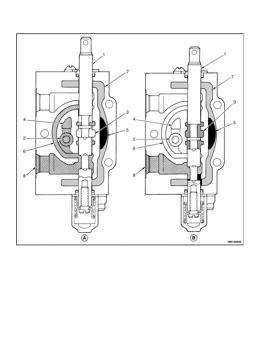
TILT SECTION
The basic operation of the tilt spool is the same as
the other spools in this control valve. The tilt control
spool that is inside the tilt spool adds an additional
sequence to the tilt forward function.
Tilt Backward
When the spool is moved to the Back tilt position, the
tilt spool causes a restriction of the oil flow through
the open center passage. See Figure 4. The increased
pressure in the parallel passage causes the oil to flow
through the check valve to the supply cavity. The oil
flows from the supply cavity through a section of the
spool to the rod side of the tilt cylinders. The check
valve prevents the movement of the load until the
system pressure is great enough to control the load.
Oil from the piston end of the tilt cylinders returns
through the main control valve to the hydraulic tank.
Tilt Forward
The tilt control spool that is inside the tilt spool oper-
ates during the Forward tilt function. See Figure 4.
The tilt control spool prevents cavitation in the pis-
ton end of the tilt cylinders. Cavitation occurs when
the available fluid does not fill the space in a closed
system. The high vacuum causes some of the fluid
to change to bubbles of gas. When cavitation occurs
in the tilt cylinders, the tilt forward function is not
smooth.
The tilt control spool permits the regulation of the
tilt speed by using the pressure from the hydraulic
pump.
The pressure must be 550 kPa (80 psi) on the piston
end of the tilt cylinders. The tilt control spool pre-
vents oil flow from the rod end of the tilt cylinders
until the pressure is 550 kPa (80 psi). This action
makes sure that a vacuum cannot occur at the piston
end of the tilt cylinders.
Relief Valve
The relief valve limits the maximum pressure within
the hydraulic system. The control valve can have one
or two relief valves. The primary relief valve is in-
stalled in the inlet section of the control valve and is
for the lift circuit. The secondary relief valve is for
the tilt and auxiliary circuits and is installed in the
section of the control valve with the lift/lower spool.
Both relief valves are the same in description and op-
eration. When the secondary relief valve is installed,
it is set at a lower pressure than the primary relief
valve. When the pressure in one of the hydraulic cir-
cuits reaches the relief valve setting, the relief valve
opens a path between the inlet and drain circuits.
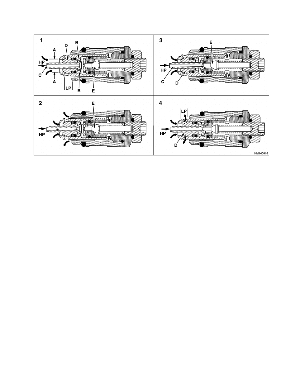
The relief valve is a poppet valve that is pilot op-
erated. There are four poppet spools in this valve.
Spools C, D, and E are used for pressure relief.
(Spool K is for vacuum relief and is not used in this
application.) This relief valve gives almost constant
relief pressure over the range of the hydraulic pump
flow. The sequence of operation is described in Fig-
ure 5.
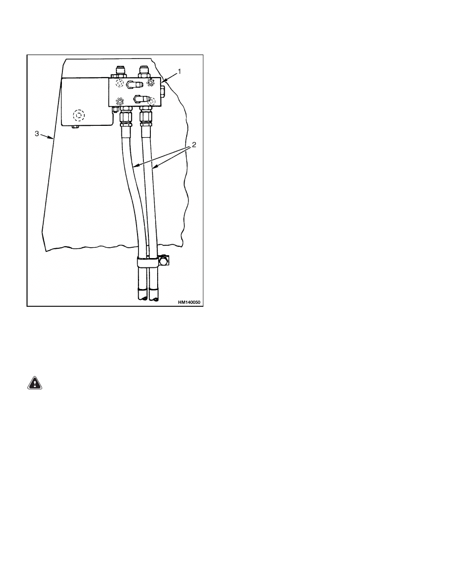
SOLENOID VALVE FOR AUXILIARY
FUNCTION
When used, this valve is installed on the front of the
cowl. See Figure 6. Together with one of the auxiliary
sections of the main control valve, the solenoid valve
provides a fifth function. Header hoses are used to
connect the attachment to the solenoid valve.
The solenoid valve is electrically actuated by a button
on the lever for the optional hydraulic functions. The
button operates only when the lever is in the left posi-
tion. (The lever is spring-loaded to the left position.)
When the button is not depressed, the lever operates
the third function the same as without the button.
When the button is depressed with the lever in the
left position, the solenoid valve controls the fourth
function. When the lever is moved to the right, it op-
erates the fifth hydraulic function.
5
Operation
2000 SRM 77
A. TILT BACKWARD
B. TILT FORWARD
1.
OPEN CENTER PASSAGE
2.
SUPPLY CAVITY
3.
TO/FROM PISTON END OF TILT CYLINDERS
4.
DRAIN CAVITY
5.
TILT SPOOL
6.
TO/FROM ROD END OF TILT CYLINDERS
7.
TILT CONTROL SPOOL
Figure 4. Tilt Spool Operation
6
2000 SRM 77
Operation
1.
STEP 1 = THE RELIEF VALVE IS CLOSED BETWEEN THE HIGH PRESSURE INLET (HP) AND THE LOW
PRESSURE (LP) DRAIN. HIGH PRESSURE OIL ENTERS THE PASSAGE AT C. THE DIFFERENCE IN
AREA BETWEEN DIAMETERS A AND B HOLDS THE POPPET SPOOL D AGAINST THE VALVE SEAT.
2.
STEP 2 = THE OIL PRESSURE IN THE HIGH PRESSURE INLET BECOMES GREATER THAN THE
SPRING FORCE OF THE PILOT POPPET E. THE PILOT POPPET E IS PUSHED FROM ITS SEAT. OIL
FLOWS AROUND THE POPPET E AND THROUGH THE PASSAGES TO THE DRAIN.
3.
STEP 3 = WHEN PILOT POPPET E OPENS, THE LOSS OF OIL PRESSURE BEHIND POPPET C CAUSES
POPPET C TO MOVE AGAINST POPPET E. THIS MOVEMENT STOPS THE FLOW OF OIL THROUGH C
AND CAUSES A LOWER PRESSURE BEHIND RELIEF VALVE POPPET D.
4.
STEP 4 = THE DIFFERENCE IN PRESSURE ON EACH SIDE OF POPPET D CAUSES POPPET D TO
OPEN. THE HIGH PRESSURE OIL THEN HAS A DIRECT PATH TO THE LOW PRESSURE DRAIN.
Figure 5. Relief Valve Operation
7
Main Control Valve Repair
2000 SRM 77
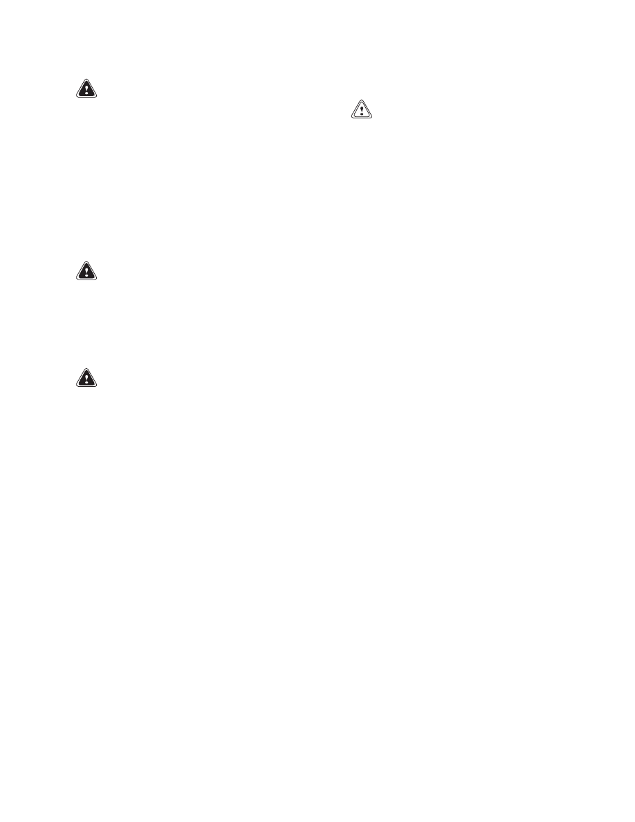
Figure 6. Solenoid Valve Installation
Legend for Figure 6
1.
SOLENOID VALVE
2.
SUPPLY/RETURN HOSES
3.
COWL
Main Control Valve Repair
REMOVE AND DISASSEMBLE
WARNING
Lower the mast before disconnecting lines
from the control valve to prevent the mast
from lowering suddenly.
1.
Disconnect lines at control valve. Put caps on
open lines.
2.
Disconnect linkage at spools.
3.
Remove bolts that hold main control valve to
frame.
NOTE: Disassemble the main control valve as nec-
essary for repairs. Most repairs to the main control
valve are the adjustment of the linkage and the re-
placement of O-rings to stop leaks. The passages in
the tilt spool are small and can need cleaning if the
hydraulic oil becomes dirty. The section normally
must be replaced if the spool or valve section is dam-
aged.
4.
Remove end cap from valve section. Carefully
pull spool from valve section.
Do not remove
spring retainers unless a spring must be re-
placed.
5.
The valve sections can be separated when the
three through bolts are removed.
The check
valves are held in the valve body by the next
section.
8
2000 SRM 77
Solenoid Valve for Auxiliary Function Repair
WARNING
The special screw in the end of the tilt spool
also holds the spring retainers. The spring is
compressed.
6.
Remove tilt control spool by removing special
screw in end of tilt spool.
7.
Carefully remove tilt control spool from tilt spool.
8.
The relief valve is normally replaced if it is dam-
aged.
CLEAN AND INSPECT
WARNING
Compressed air can move particles so that they
cause injury to the user or to other personnel.
Make sure that the path of the compressed air
is away from all personnel.
Wear protective
goggles or a face shield to prevent injury to
eyes.
WARNING
Cleaning solvents can be flammable and toxic,
and can cause skin irritation.
When using
cleaning solvents, always follow the recom-
mendations of the manufacturer.
Clean all parts of control valve with solvent. Dry
parts with compressed air.
1.
Check spools and bores for defects. If a spool
or the bores have damage, the complete control
valve must be replaced. Make sure spools move
freely in bores.
2.
Check the check valves and relief valve for dam-
age. Replace parts as necessary.
ASSEMBLE
CAUTION
Before installing the parts into the valve body,
make sure all parts are clean. Replace all the
seals and the O-rings. Lubricate all the parts
with clean hydraulic oil during assembly.
1.
Install new seals in bores of sections.
Install
new O-ring seals between sections. Install check
valves and springs and assemble the sections.
Tighten nuts on the 3/8 inch through bolts to
45 N•m (35 lbf ft). Tighten nuts on the 5/16 inch
through bolts to 20 N•m (15 lbf ft).
2.
If return springs were removed from control
spools, install spring retainers. During assem-
bly, use new O-rings for parts of tilt control spool.
Do not damage O-rings during installation.
3.
Lubricate spools with clean hydraulic oil. Make
sure dirt does not get on any of the parts. Care-
fully install spools in valve body. Install seal re-
tainers and covers for return springs.
4.
Install relief valve. Adjust relief setting for hy-
draulic system as described in Pressure Relief
Valve Check and Adjustment.
INSTALL
1.
Install control valve to frame.
2.
Connect linkage at spools.
3.
Connect hydraulic lines to control valve.
4.
Add hydraulic oil to tank. See the section Peri-
odic Maintenance for correct specifications.
5.
Operate system and check for leaks and correct
operation.
Adjust relief valve as described in
Pressure Relief Valve Check and Adjustment.
Solenoid Valve for Auxiliary Function Repair
REMOVE AND DISASSEMBLE
NOTE: Step 1 through Step 3 provide access to the
coil without removing the solenoid valve. To test the
coil, see Troubleshooting for the solenoid valve.
1.
Loosen bolt for wire clamp on bottom of coil cover.
See Figure 7.
2.
Remove bolts for coil cover and carefully remove
cover from valve.
3.
With the red and white wires attached, discon-
nect diode assembly from terminals on coil.
9
Solenoid Valve for Auxiliary Function Repair
2000 SRM 77
Figure 7. Solenoid Valve and Control Circuit
10
2000 SRM 77
Solenoid Valve for Auxiliary Function Repair
Legend for Figure 7
1.
BOLT
2.
CLAMP
3.
LOCKWASHER
4.
NUT
5.
COIL COVER
6.
BOLT
7.
NUT
8.
LOCKWASHER
9.
END PLATE
10. COIL
11. SOLENOID VALVE
12. NUT
13. WASHER
14. BOLT
15. FITTING
16. O-RING
17. FITTING
18. O-RING
19. CONTROL KNOB
20. STRAP CLAMP
21. WIRE ASSEMBLY
22. DIODE ASSEMBLY
23. WIRING HARNESS
24. GROMMET
25. DIODE COLOR-CODE
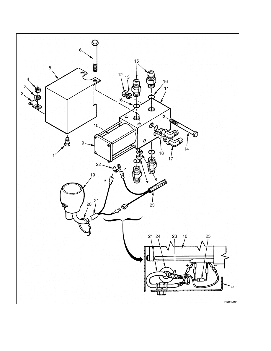
4.
To remove complete solenoid valve assembly, con-
tinue with Step 5. To remove coil from valve,
loosen screws for end plate. See Figure 8. Re-
move screws, end plate, and coil.
1.
SOLENOID VALVE
2.
COIL
3.
END PLATE
Figure 8. Solenoid Valve and Coil
NOTE: For assembly, make a note of the position of
the coil terminals in relation to the valve ports.
5.
Put tags on hoses at solenoid valve. Disconnect
hoses at solenoid valve.
6.
Remove nuts and washers from mount bolts, and
pull solenoid valve from cowl.
ASSEMBLE AND INSTALL
1.
To install a coil on the solenoid valve, proceed
with Step 2. If the solenoid valve assembly was
removed from the lift truck, install it as follows:
a. Install two mount bolts through valve.
b. Make sure all four grommets are in the cowl,
then install valve on grommets.
Tighten
nuts.
c.
Install supply and return hoses and header
hoses on solenoid valve.
2.
If a bad coil was removed, install a new coil as
shown in Figure 9. Make sure the coil terminals
are in the correct position. Tighten screws for
end plate to 4.5 to 5.6 N•m (40 to 50 lbf in).
NOTE: Make sure wires and diode are connected as
shown in Figure 7. The diode must be installed with
color-code band toward positive terminal.
3.
Connect diode assembly with red and white wires
at coil terminals.
4.
Put coil cover on valve. Make sure control switch
wire is under wire clamp when cover is installed
on valve.
5.
Install bolts, lockwashers, and nuts for cover.
Tighten nuts for cover and wire clamp.
11

Pressure Relief Valve Check and Adjustment
2000 SRM 77
TROUBLESHOOTING
If the solenoid valve does not operate, do the follow-
ing steps:
1.
Check the 7.5 amp fuse for the solenoid valve on
the fuse panel.
2.
Check for loose electrical connections:
a. Ignition switch: Check the black wire at the
accessory terminal of the switch connector
body.
b. Control knob button:
Remove snap ring
and knob cover. Check wire connectors and
switch connections.
c.
Solenoid valve coil: Remove coil cover. See
Figure 7.
Check diode connections to coil
terminals. Check connections of the red and
white wires to diode assembly terminals.
Check connection of the black wire.
d. Cowl ground stud: Make sure there are no
loose ground wires.
3.
Remove diode assembly. Test diode with an ohm-
meter for high resistance in one direction and no
resistance in the other direction. If there is no re-
sistance or infinite resistance in both directions,
replace diode.
NOTE: Make sure the wires and the diode are con-
nected as shown in Figure 7. The diode must be in-
stalled with the color-code band toward the positive
terminal.
4.
Disconnect the red and white wires from the
diode assembly terminals.
Connect voltmeter
across the wire terminals, check for current
when control knob button is depressed.
a. If there is no current, check wiring for short
circuits.
b. If there is current, test coil. See Step 5.
5.
Test coil for continuity by connecting an ohmme-
ter lead to each coil terminal. Put ohmmeter on
the R × 1 scale.
a. If there is no ohmmeter reading, the coil is
bad. Replace coil.
b. If there is an ohmmeter reading, the coil is
good.
If the coil is good, but the solenoid
valve does not energize when the button is
depressed, the solenoid valve is bad. Replace
solenoid valve assembly.
Pressure Relief Valve Check and Adjustment
NOTE: The control valve can have two relief valves: a
primary relief valve and a secondary relief valve. The
primary relief valve is always on the inlet section of
the control valve. The secondary relief valve is on the
section with the lift/lower spool.
PRIMARY RELIEF VALVE
1.
Connect a 0 to 25 MPa (0 to 3500 psi) gauge to
the test port.
E1.25-1.75XL
(E25-35XL)
and
E/J2.00-
3.00XL (E/J40-60XL) lift trucks: Install a
fitting and gauge in the port below the return
line at the control valve.
S/H1.25-1.75XL (S/H25-35XL) lift trucks:
Test port is near the left-hand tilt cylinder.
S/H2.00-3.00XL
(S/H40-60XL),
E3.50-
5.50XL
(E70-120XL,
E70-120XL
3
),
and
E3.50-5.50XL,
E4.50XLS
(E70-120Z,
E100ZS) [D098] lift trucks: Test port is
near the inlet port of the main control valve.
H3.50-5.00XL
(H70-110XL)
and
S3.50-
5.50XL (S70-120XL) lift trucks: Test port is
on the control valve at the fitting for the lift
cylinders.
2.
If installed, remove acorn nut from relief valve.
Loosen jam nut.
3.
Start engine and operate hydraulic system to
warm oil temperature to 55 to 65 C (130 to
150 F). Run engine at approximately 1000 rpm
when making pressure checks.
12

2000 SRM 77
Pressure Relief Valve Check and Adjustment
4.
E/S/H1.25-1.75XL (E/S/H25-35XL) lift trucks:
Tilt mast backward until it stops. Hold the lever
and check the reading of the gauge when the re-
lief valve opens. Turn the adjustment screw as
necessary to change the setting. See Specifica-
tions for the correct setting. Tighten the jam nut
when the adjustment is correct.
5.
E/J/S/H2.00-3.00XL (E/J/S/H40-60XL), H3.50-
5.00XL (H70-110XL), and S3.50-5.50XL (S70-
120XL) lift trucks: Check relief valve by raising
mast until it stops. Hold lever and check read-
ing of the gauge when relief valve opens. Turn
adjustment as necessary to change setting. See
Specifications for correct setting. Tighten jam
nut when adjustment is correct.
6.
Remove gauge when checks are complete.
SECONDARY RELIEF VALVE
1.
Connect a 0 to 20 MPa (0 to 3000 psi) gauge to
the test port.
S/H1.25-1.75XL (S/H25-35XL) lift trucks:
Test port is near the left-hand tilt cylinder.
S/H2.00-3.00XL (S/H40-60XL) lift trucks:
Test port is near the inlet port of the main
control valve.
E/J2.00-3.00XL (E/J40-60XL) lift trucks:
Install a gauge and fitting at a port for the rod
side of the tilt cylinders.
H3.50-5.00XL (H70-110XL) lift trucks: Test
port is on the control valve at the tee fitting for
the tilt cylinders.
S/E3.50-5.50XL
(S/E70-120XL,
E70-120XL
3
), and E3.50-5.50XL, E4.50XLS
(E70-120Z, E100ZS) [D098] lift trucks:
Connect a gauge to the forward tilt port on
the main control valve.
2.
If installed, remove acorn nut from relief valve.
Loosen jam nut.
3.
Start engine and operate hydraulic system to
warm oil temperature to 55 to 65 C (130 to
150 F). Run engine at approximately 1000 rpm
when making pressure checks.
4.
S/H1.25-1.75XL (S/H25-35XL) lift trucks: Tilt
mast backward until it stops. Hold lever and
check reading of the gauge when relief valve
opens. Turn adjustment screw as necessary to
change setting.
See Specifications for correct
setting.
Tighten jam nut when adjustment is
correct.
5.
E/J/S/H2.00-3.00XL
(E/J/S/H40-60XL)
lift
trucks: Check secondary relief valve by tilting
mast backward until it stops. Hold lever and
check reading of the gauge when relief valve
opens. Turn adjustment screw as necessary to
change the setting. See Specifications for correct
setting.
Tighten jam nut when adjustment is
correct.
6.
H3.50-5.00XL (H70-110XL) and S3.50-5.50XL
(S70-120XL) lift trucks: Tilt mast forward un-
til it stops. Hold lever and check reading of the
gauge when relief valve opens. Turn adjustment
screw as necessary to change setting. See Spec-
ifications for correct setting. Tighten jam nut
when adjustment is correct.
7.
Remove gauge when checks are complete.
13
Control Lever Arrangement and Adjustment
2000 SRM 77
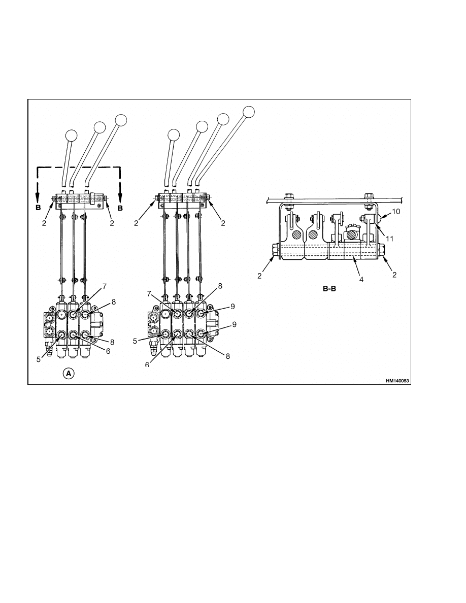
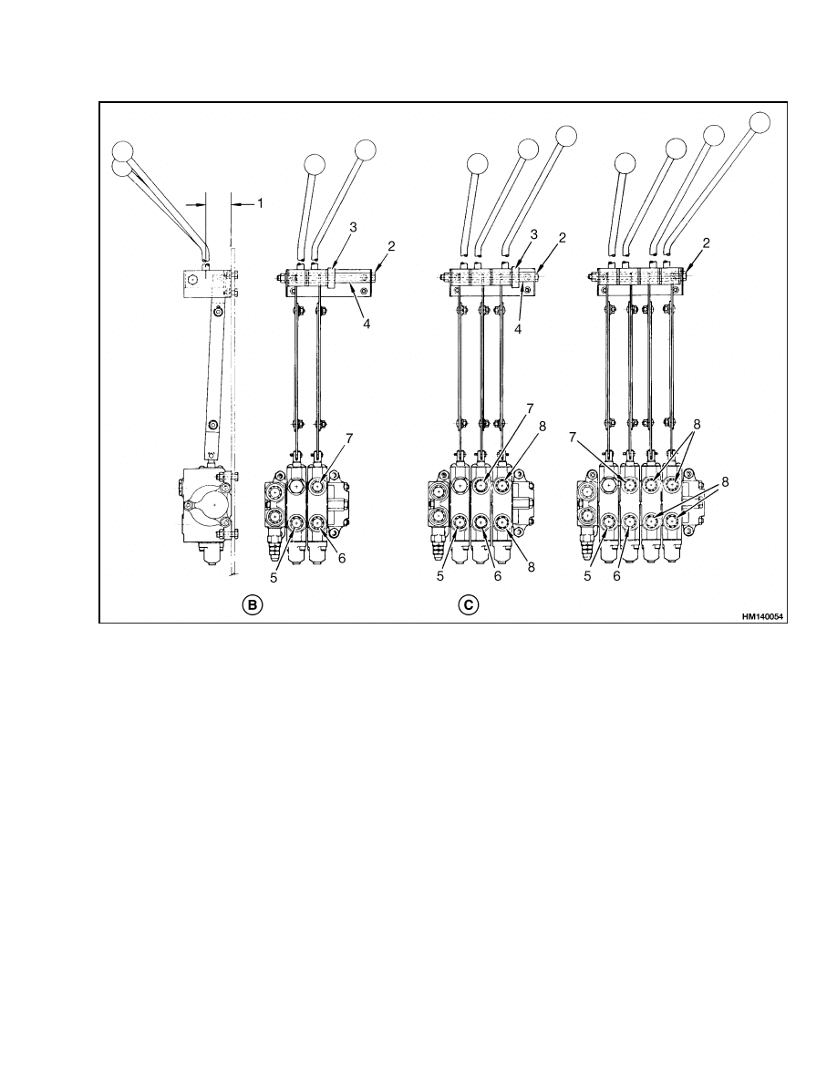
Control Lever Arrangement and Adjustment
NOTE: For electric lift trucks, see the section Hydraulic System 1900 SRM 286 section for the arrangement
and adjustment of the control valve levers. See Figure 9.
Figure 9. Control Lever Arrangement (Sheet 1 of 2)
14
2000 SRM 77
Control Lever Arrangement and Adjustment
NOTE: AUXILIARY CONTROL LEVER MUST BE PUSHED TO THE RIGHT TO ENGAGE THE THIRD CONTROL
VALVE SPOOL. WHEN RELEASED, THE CONTROL LEVER MUST RETURN TO THE LEFT.
A. ALL UNITS [EXCEPT EARLIER PRODUCTION
H2.00-3.00XL (H40-60XL)]
B. ALL UNITS
C. EARLIER PRODUCTION H2.00-3.00XL
(H40-60XL) UNITS
1.
ADJUST LENGTH OF LINKAGE SO LEVERS
ARE 51.5 mm (2.02 in.) FROM COWL IN
NEUTRAL POSITION
2.
CAPSCREW [TIGHTEN TO 19 N•m (14 lbf ft)]
3.
COLLAR, TIGHTEN SETSCREW TO 7 N•m
(62 lbf ft)
4.
PIVOT SPACER
5.
TO THE LIFT CYLINDER
6.
TILT BACKWARD
7.
TILT FORWARD
8.
AUXILIARY FUNCTION [FOR SIDESHIFT
CARRIAGE: UPPER PORT IS "Y" = LEFT
SIDESHIFT (LEVER FORWARD). LOWER
PORT IS "X" = RIGHT SIDESHIFT (LEVER
BACKWARD)]
9.
AUXILIARY FUNCTION
10. CAPSCREW
11. SPACER
Figure 9. Control Lever Arrangement (Sheet 2 of 2)
15
Troubleshooting
2000 SRM 77
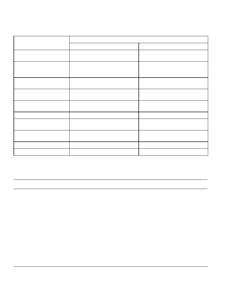
Specifications
Relief Valve Settings
Unit
Primary Relief Valve
Secondary Relief Valve
S/H/E1.25-1.75XL
(S/H/E25-35XL)
15.15 to 15.85 MPa (2200 to 2300 psi)
Not Used
S/H2.00-3.00XL
(S/H40-60XL) (With VISTA
upright)
19.25 to 19.95 MPa (2800 to 2900 psi)
15.15 to 15.85 MPa (2200 to 2300 psi)
H2.00-3.00XL (H40-60XL)
(Without VISTA upright)
17.55 to 18.25 MPa (2550 to 2650 psi)
15.15 to 15.85 MPa (2200 to 2300 psi)
E/J2.00-3.00XL (E/J40-60XL)
36/48 Volt
18.90 to 19.30 MPa (2750 to 2950 psi)
15.15 to 15.85 MPa (2200 to 2300 psi)
E/J2.00-3.00XL (E/J40-60XL)
72/80 Volt
18.60 to 19.00 MPa (2650 to 2850 psi)
15.15 to 15.85 MPa (2200 to 2300 psi)
H3.50-5.00XL (H70-110XL)
21.4 MPa (3100 psi)
15.15 to 15.85 MPa (2200 to 2300 psi)
E3.50-5.50XL (E70-120XL,
E70-120XL
3
)
20.7 MPa (3000 psi)
15.15 to 15.85 MPa (2200 to 2300 psi)
E3.50-5.50XL, E4.50XLS
(E70-120Z, E100ZS) [D098]
20.7 MPa (3000 psi)
15.15 to 15.85 MPa (2200 to 2300 psi)
S3.50-5.50XL (S70-120XL)
21.4 MPa (3100 psi)
15.15 to 15.85 MPa (2200 to 2300 psi)
N30-40CR
13.1 to 14.5 MPa (2000 to 2100 psi)
Not Used
Troubleshooting
PROBLEM
POSSIBLE CAUSE
PROCEDURE OR ACTION
Slow or no movement of
cylinders.
Air is in the hydraulic system.
Remove air from hydraulic system.
The hydraulic pump is worn or dam-
aged.
Repair or replace hydraulic pump.
Restriction in the hydraulic lines.
Repair hydraulic lines.
Cylinder seals are damaged.
Repair cylinders.
Load is greater than capacity.
Reduce load.
Linkage is disconnected or damaged.
Repair and adjust linkage for control
levers.
Pressure relief valve(s) is not ad-
justed correctly or is damaged.
Repair or adjust relief valve(s).
16

2000 SRM 77
Troubleshooting
PROBLEM
POSSIBLE CAUSE
PROCEDURE OR ACTION
Slow or no movement of
cylinders. (Cont.)
Large leaks between spool and bore.
Replace valve section.
Spool is not fully extended or re-
tracted.
Adjust linkage to spool.
Oil leaks at the end of a
spool.
Seal for spool is damaged.
Replace seal.
Spool is damaged.
Replace valve section.
Valve body is damaged.
Replace valve section.
Spool will not move or is dif-
ficult to move.
Linkage is disconnected or damaged.
Repair and adjust linkage.
Return spring is damaged.
Replace spring.
The spool or bore is damaged.
Replace valve section.
Spool will not return to
NEUTRAL.
Linkage is disconnected or damaged.
Repair and adjust linkage.
Return spring is damaged.
Replace spring.
Dirt between spool and the bore.
Clean valve.
Spool is bent or damaged.
Replace valve section.
Hydraulic pressure is above
specifications.
Pressure relief valve(s) is not ad-
justed correctly or is damaged.
Repair or adjust relief valve(s).
Restriction in return line.
Clean or replace return line or filter.
Tilt cylinders extend when
the tilt spool is in the NEU-
TRAL position.
Cylinder seal have leaks.
Repair tilt cylinders.
Oil leaks between control valve spool
and bore.
Replace valve section.
Hydraulic lines have leaks.
Repair or tighten lines or fittings.
17

Troubleshooting
2000 SRM 77
PROBLEM
POSSIBLE CAUSE
PROCEDURE OR ACTION
Tilt cylinders extend sud-
denly when the tilt spool is
moved to BACK TILT posi-
tion.
Check valve for tilt spool is damaged.
Replace check valve.
Tilt cylinders extend sud-
denly when the tilt spool is
moved to FORWARD TILT
position.
Tilt control spool inside the tilt spool
is damaged.
Replace valve section.
Lift cylinders retract when
the lift spool is in the NEU-
TRAL position.
Check valve for the lift spool is dam-
aged.
Replace check valve.
Cylinder seals have leaks.
Repair lift cylinders.
Hydraulic lines have leaks.
Repair or tighten lines or fittings.
Leaks between the lift spool and the
bore.
Replace valve section.
18


TECHNICAL PUBLICATIONS
2000 SRM 77
3/05 (7/00)(3/96)(4/88)(9/84)(3/83)(10/81)(6/81) Printed in United Kingdom
Document Outline
- toc
Wyszukiwarka
Podobne podstrony:
1554631 2000SRM1085 (03 2004) UK EN
897953 1600SRM0639 (03 2005) UK EN
1598459 1900SRM1213 (03 2005) UK EN
897956 1900SRM0642 (03 2005) UK EN
897963 4500SRM0649 (03 2005) UK EN
1573930 0600SRM1172 (03 2005) UK EN
1586985 2200SRM1178 (03 2005) UK EN
897345 1400SRM0413 (03 2005) UK EN
1531815 1800SRM1040 (03 2005) UK EN
897875 8000SRM0616 (03 2005) UK EN
897961 2200SRM0647 (03 2005) UK EN
1597925 0700SRM1211 (03 2005) UK EN
1586982 0100SRM1177 (03 2005) UK EN
1466169 4000SRM0741 (03 2005) UK EN
1495208 8000SRM0949 (03 2005) UK EN
1458783 8000SRM0592 (03 2005) UK EN
1589731 2200SRM1184 (03 2005) UK EN
1531821 1800SRM1037 (03 2005) UK EN
więcej podobnych podstron