BOOM
REACHSTACKER
RS45-27CH, RS45-30CH, RS45-27IH, RS46-33CH,
RS46-30IH, RS46-36CH, RS46-33IH [A222]
PART NO. 897963
4500 SRM 649

SAFETY PRECAUTIONS
MAINTENANCE AND REPAIR
• When lifting parts or assemblies, make sure all slings, chains, or cables are correctly
fastened, and that the load being lifted is balanced. Make sure the crane, cables, and
chains have the capacity to support the weight of the load.
• Do not lift heavy parts by hand, use a lifting mechanism.
• Wear safety glasses.
• DISCONNECT THE BATTERY CONNECTOR before doing any maintenance or repair
on electric lift trucks. Disconnect the battery ground cable on internal combustion lift
trucks.
• Always use correct blocks to prevent the unit from rolling or falling. See HOW TO PUT
THE LIFT TRUCK ON BLOCKS in the Operating Manual or the Periodic Mainte-
nance section.
• Keep the unit clean and the working area clean and orderly.
• Use the correct tools for the job.
• Keep the tools clean and in good condition.
• Always use HYSTER APPROVED parts when making repairs. Replacement parts
must meet or exceed the specifications of the original equipment manufacturer.
• Make sure all nuts, bolts, snap rings, and other fastening devices are removed before
using force to remove parts.
• Always fasten a DO NOT OPERATE tag to the controls of the unit when making repairs,
or if the unit needs repairs.
• Be sure to follow the WARNING and CAUTION notes in the instructions.
• Gasoline, Liquid Petroleum Gas (LPG), Compressed Natural Gas (CNG), and Diesel fuel
are flammable. Be sure to follow the necessary safety precautions when handling these
fuels and when working on these fuel systems.
• Batteries generate flammable gas when they are being charged. Keep fire and sparks
away from the area. Make sure the area is well ventilated.
NOTE: The following symbols and words indicate safety information in this
manual:
WARNING
Indicates a condition that can cause immediate death or injury!
CAUTION
Indicates a condition that can cause property damage!

Boom
Table of Contents
TABLE OF CONTENTS
General ...............................................................................................................................................................
Description and Operation ................................................................................................................................
Boom...............................................................................................................................................................
Hydraulic System ..........................................................................................................................................
Boom Repair .......................................................................................................................................................
Models Up to April 2005................................................................................................................................
Remove.......................................................................................................................................................
Disassemble ...............................................................................................................................................
Clean and Inspect......................................................................................................................................
Assemble ....................................................................................................................................................
Install .........................................................................................................................................................
Models Starting April 2005 ...........................................................................................................................
Remove.......................................................................................................................................................
Disassemble ...............................................................................................................................................
Clean and Inspect......................................................................................................................................
Assemble ....................................................................................................................................................
Install .........................................................................................................................................................
Dampening Cylinder Repair..............................................................................................................................
Models Up to April 2005................................................................................................................................
Remove.......................................................................................................................................................
Disassemble ...............................................................................................................................................
Clean ..........................................................................................................................................................
Inspect........................................................................................................................................................
Assemble ....................................................................................................................................................
Install .........................................................................................................................................................
Models Starting April 2005 ...........................................................................................................................
Remove.......................................................................................................................................................
Disassemble ...............................................................................................................................................
Clean ..........................................................................................................................................................
Inspect........................................................................................................................................................
Assemble ....................................................................................................................................................
Install .........................................................................................................................................................
Extension Cylinder Repair ................................................................................................................................
Remove ...........................................................................................................................................................
Disassemble ...................................................................................................................................................
Clean ..............................................................................................................................................................
Inspect ............................................................................................................................................................
Assemble ........................................................................................................................................................
Install .............................................................................................................................................................
Lift Cylinders Repair .........................................................................................................................................
Remove ...........................................................................................................................................................
Disassemble ...................................................................................................................................................
Clean ..............................................................................................................................................................
Inspect ............................................................................................................................................................
Assemble ........................................................................................................................................................
Install .............................................................................................................................................................
Troubleshooting..................................................................................................................................................
Schematics..........................................................................................................................................................
©2005 HYSTER COMPANY
i

Table of Contents
Boom
TABLE OF CONTENTS (Continued)
This section is for the following models:
RS45-27CH, RS45-30CH, RS45-27IH, RS46-33CH, RS46-30IH,
RS46-36CH, RS46-33IH [A222]
ii

4500 SRM 649
Description and Operation
General
This section has the description and repair procedures for the boom assembly. This section also has removal,
disassembly, cleaning, inspection, assembly, and installation procedures for the dampening cylinder, extension
cylinder, and lift cylinders.
Description and Operation
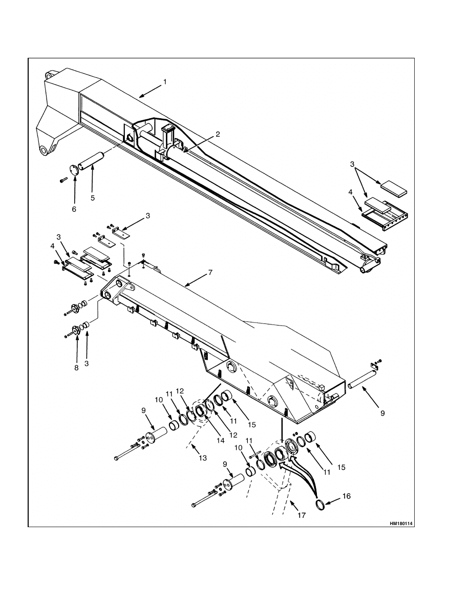
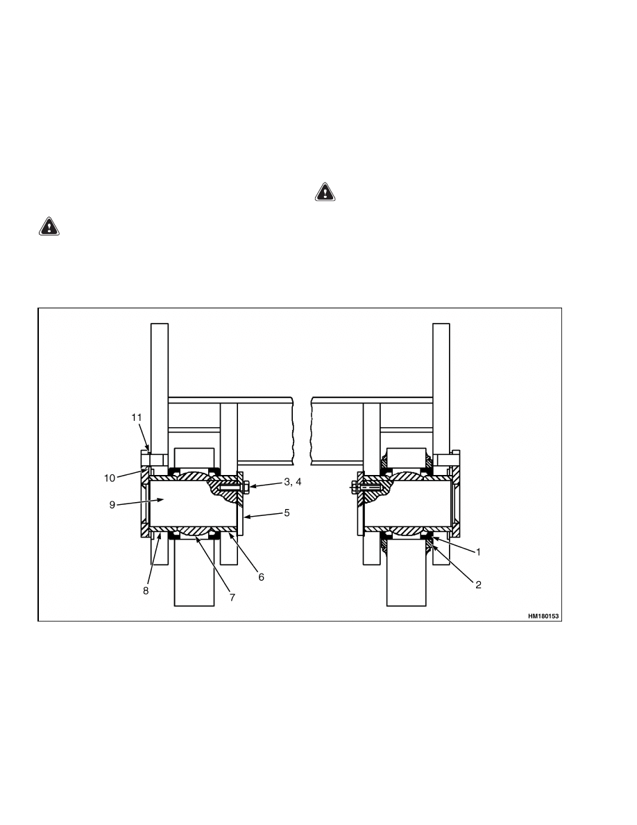
BOOM
The boom is the support for the attachment/rotator
attachment. See Figure 1. The boom pivots on two
support towers at the back of the lift truck. Two lift
cylinders mount to the boom and the lift truck in
front of the support towers and allow the operator
to raise or lower the boom. The boom has an inner
section that can be extended from the outer section
to allow the attachment to reach over one container
to a container behind it. The outer boom section has
the pivot and lift cylinder mounts. The inner section
rides on wear plates and is fastened to the rod end of
the extension cylinder by a pin. The shell of the ex-
tension cylinder has wear pads at the front that ride
on the inside of the inner boom. The back end of the
shell mounts to the back of the outer boom by a pin
and bushings.
The boom has a yoke at the inner end that connects
to the attachment/rotator attachment. The attach-
ment pivots on pins in the yoke, but the movement
is controlled by the dampening cylinder that is at-
tached between the boom and the attachment.
The hydraulic hoses for the dampening cylinder
and for the attachment are held in a support chain
that keeps the hoses and wiring from bending at
the wrong angles when the boom is extended or
retracted.
HYDRAULIC SYSTEM
The boom lift cylinders and the boom extension cylin-
der are all double-acting cylinders. The boom cylin-
ders are controlled by two parallel hydraulic valves
mounted on the lift truck. A large volume hydraulic
pump and a flow divider provide enough oil flow to
operate the boom cylinders at full speed at all engine
speeds. The hydraulic system for the boom cylinders
is described in the manual for the lift truck.
Each of the two lift cylinders and the extension
cylinder has a valve mounted on the cylinder to
prevent any movement of the rod until there is hy-
draulic pressure at the pressure port. The oil from
the opposite side of the cylinder cannot return to the
tank until there is pressure at the other port. This
arrangement prevents even the smallest movement
of the rod caused by leaks in the cylinder.
1
Description and Operation
4500 SRM 649
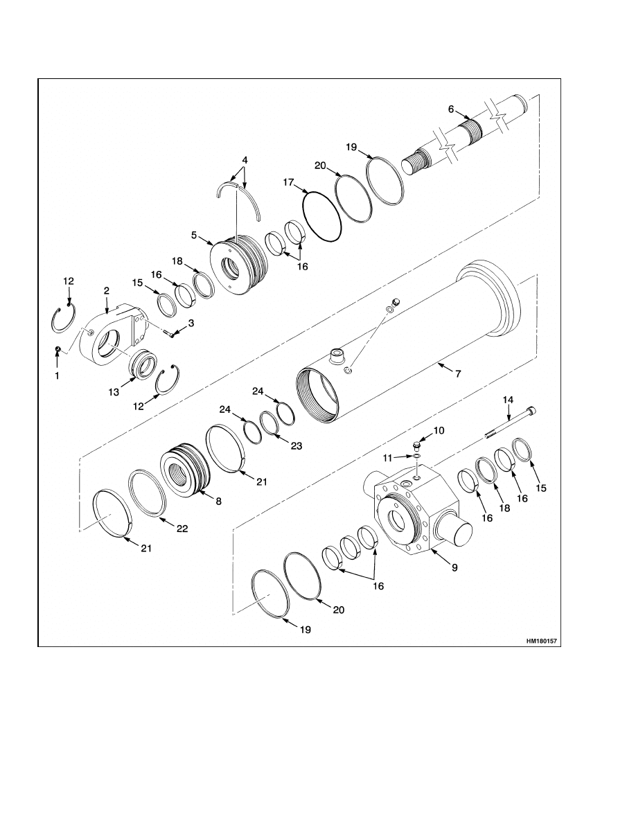
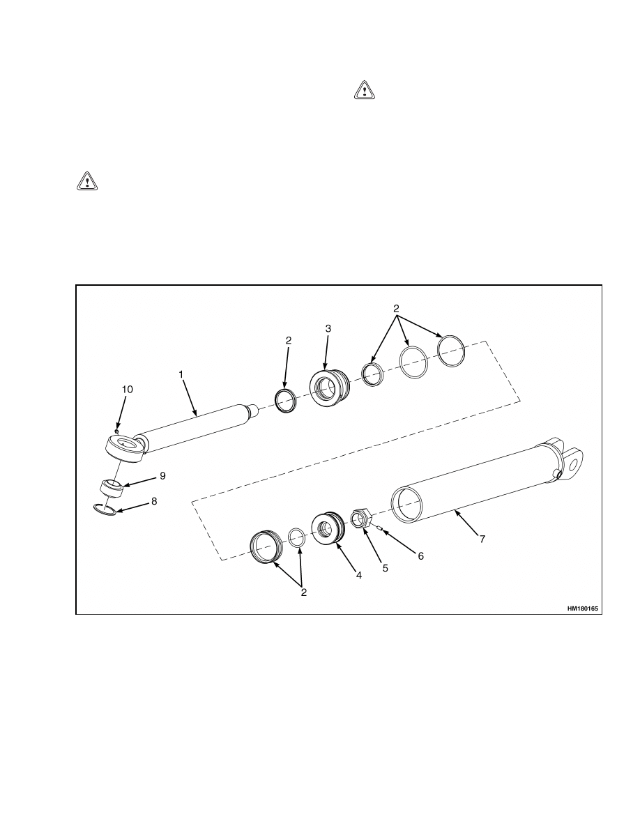
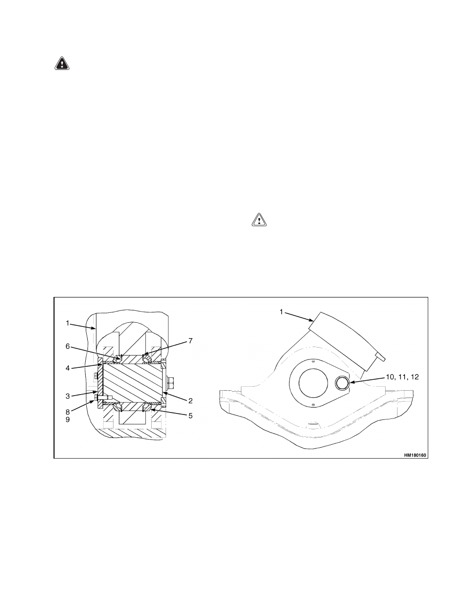
Figure 1. Boom Assembly up to April 2005
2

4500 SRM 649
Description and Operation
Legend for Figure 1
1.
INNER BOOM
2.
EXTENSION CYLINDER
3.
WEAR PADS
4.
RETAINER
5.
PIN
6.
CAP
7.
OUTER BOOM
8.
ADJUSTABLE RETAINERS
9.
PIN
10. SPACERS
11. SEALS
12. SNAP RINGS
13. LIFT CYLINDERS
14. SPHERICAL BUSHINGS
15. THREADED CAPS
16. SPACERS (ALTERNATIVE)
17. BOOM PIVOTS
3
Description and Operation
4500 SRM 649
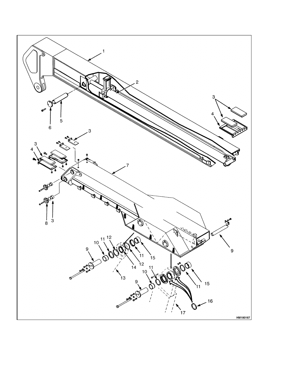
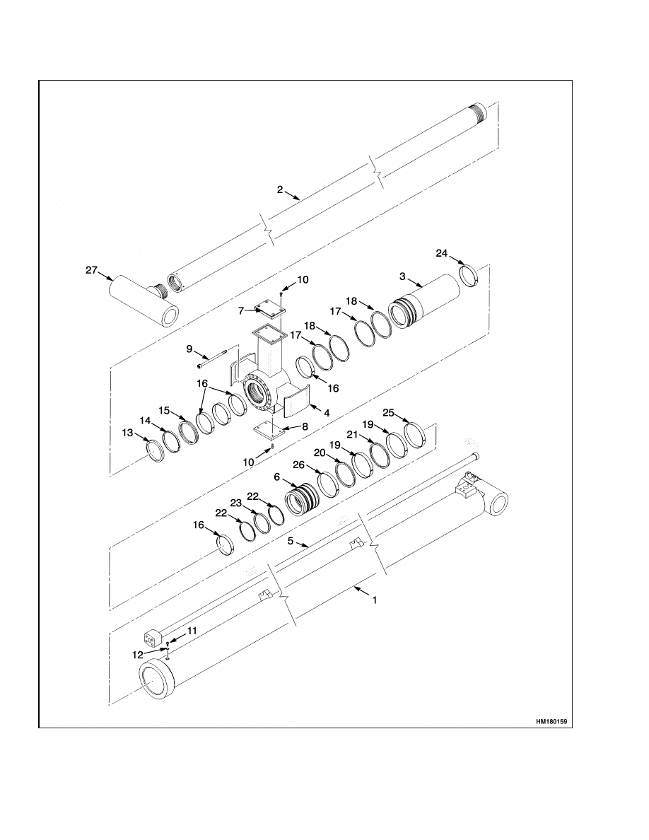
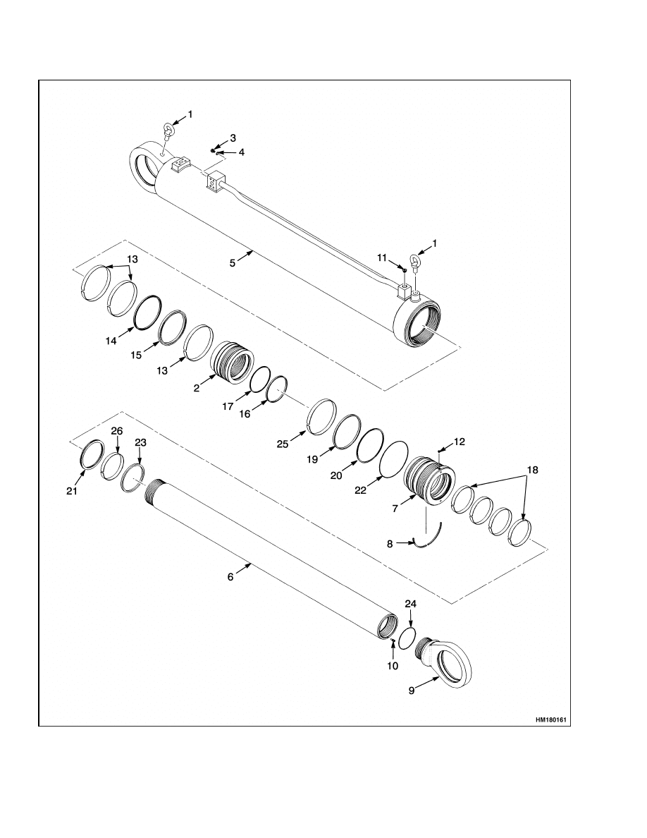
Figure 2. Boom Assembly Starting April 2005
4
4500 SRM 649
Boom Repair
Legend for Figure 2
1.
INNER BOOM
2.
EXTENSION CYLINDER
3.
WEAR PADS
4.
RETAINER
5.
PIN
6.
CAP
7.
OUTER BOOM
8.
ADJUSTABLE RETAINERS
9.
PIN
10. SPACERS
11. SEALS
12. SNAP RINGS
13. LIFT CYLINDERS
14. SPHERICAL BUSHINGS
15. THREADED CAPS
16. SPACERS (ALTERNATIVE)
17. BOOM PIVOTS
Boom Repair
MODELS UP TO APRIL 2005
Remove
Repairs to parts of the boom can be made with the
boom installed. Remove the complete boom only if
necessary.
1.
Fully retract the boom.
2.
Place the attachment on a loaded container.
3.
Apply the parking brake.
WARNING
Do not disconnect any hydraulic lines when the
engine is running or personal injury may oc-
cur.
4.
Shut down the engine.
NOTE: Move all control levers back and forth a min-
imum of 20 times to remove all hydraulic pressure
from the pilot system.
5.
Put identification tags on hydraulic lines and
electrical connectors.
6.
Disconnect the two electrical connectors between
the boom and the rotator frame.
7.
Disconnect the dampening cylinder as follows:
a. Put identification tags on the hydraulic lines
during removal.
b. Disconnect the hydraulic lines at the damp-
ening cylinder. Put caps on the open lines.
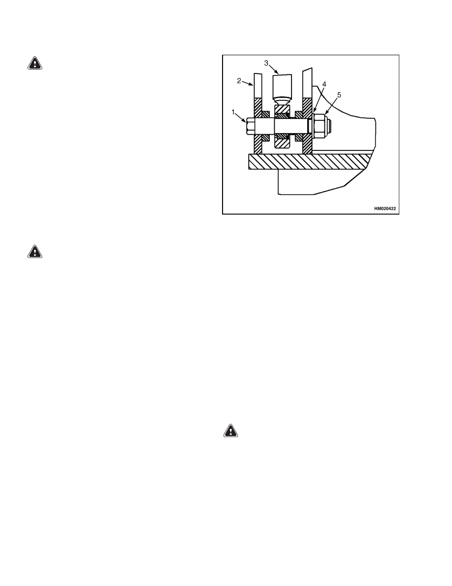
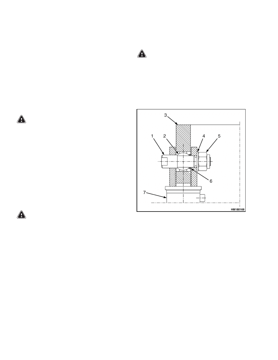
c.
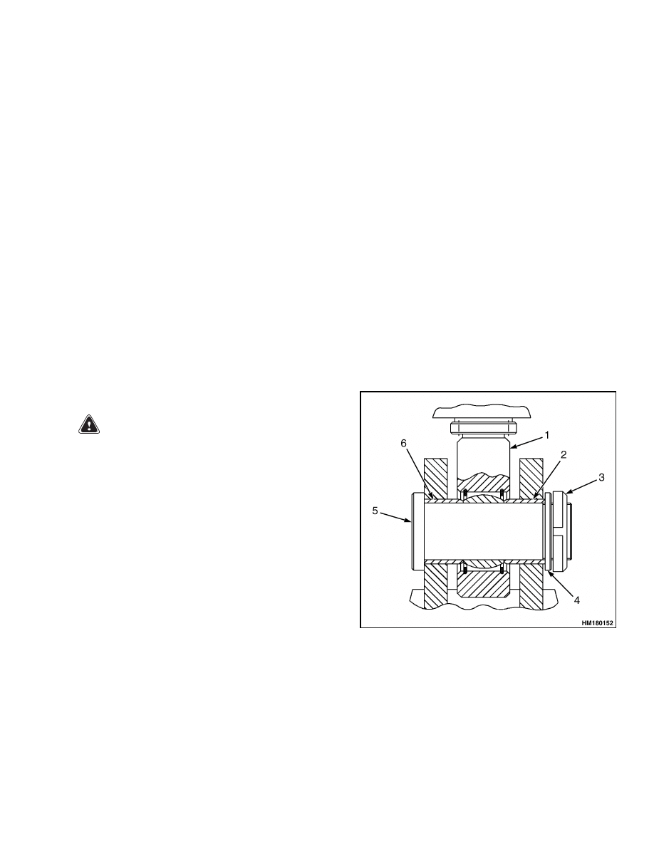
Disconnect the dampening cylinder at the ro-
tator frame by removing the lock ring and
locking disc from the pin. See Figure 3.
d. Push the pin through the spherical bushing
in the rod end with a drift.
e.
Remove the pin on the other dampening
cylinder using the same procedure.
f.
Remove the two spacers.
1.
DAMPENING
CYLINDER ROD
END
2.
SPACER
3.
LOCK RING
4.
LOCKING DISC
5.
PIN
6.
SPACER
Figure 3. Dampening Cylinder to Rotator
Frame Mounting up to April 2005
5
Boom Repair
4500 SRM 649
8.
Disconnect the boom from the rotator frame as
follows:
a. Disconnect the hydraulic lines between the
boom and rotator frame.
Put caps on the
open lines.
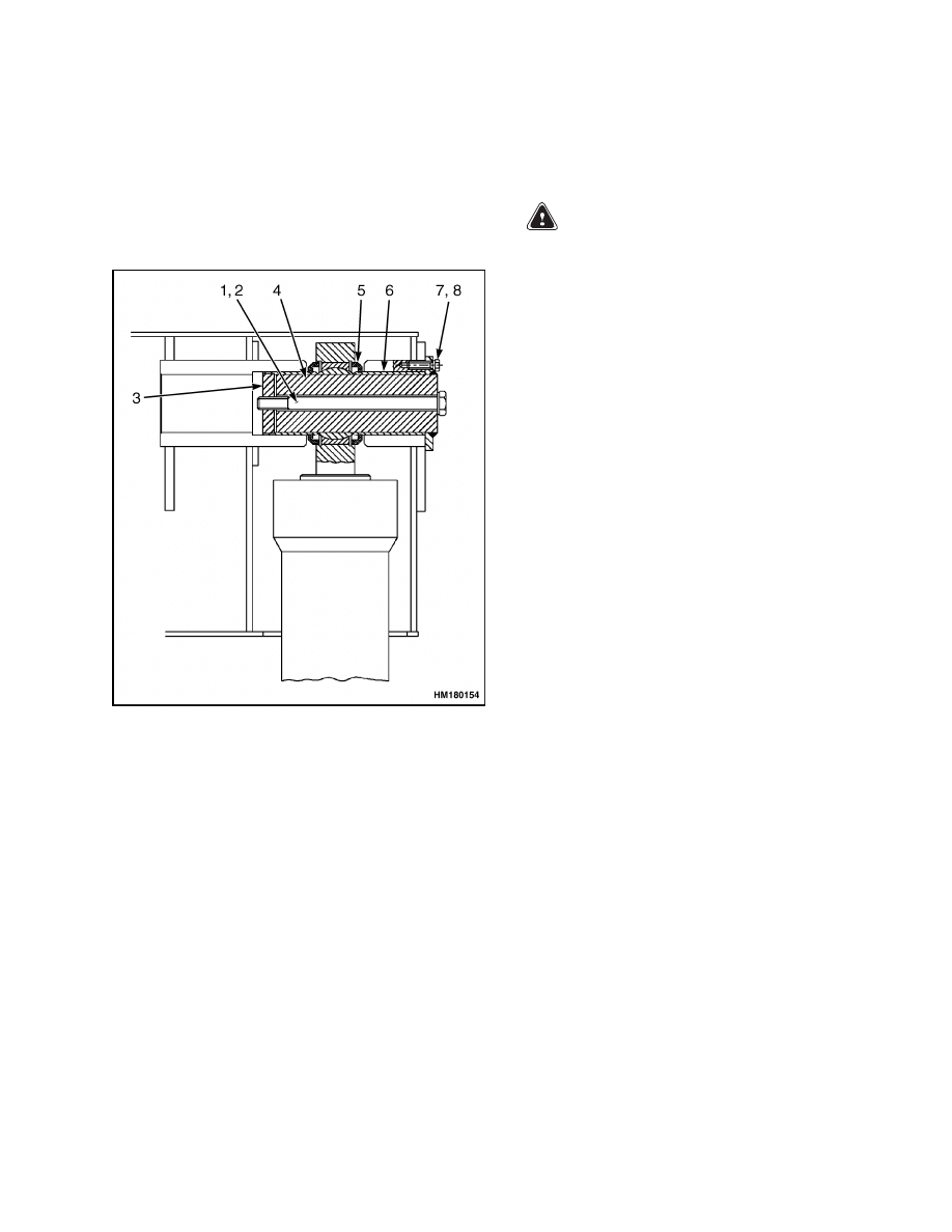
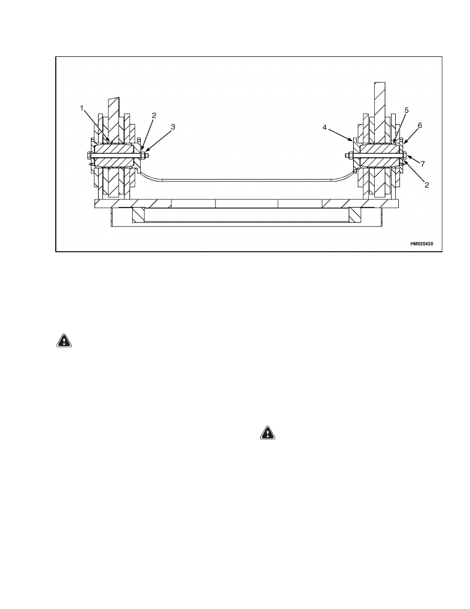
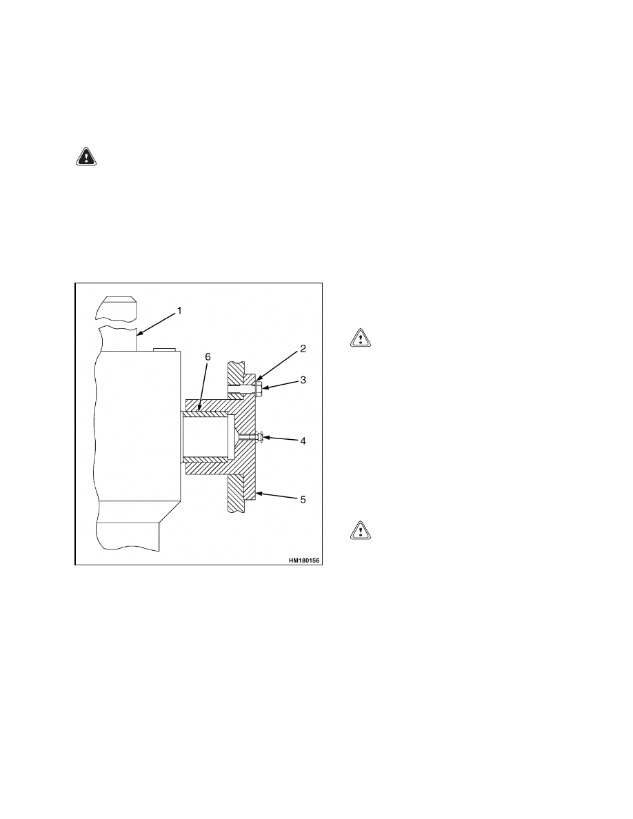
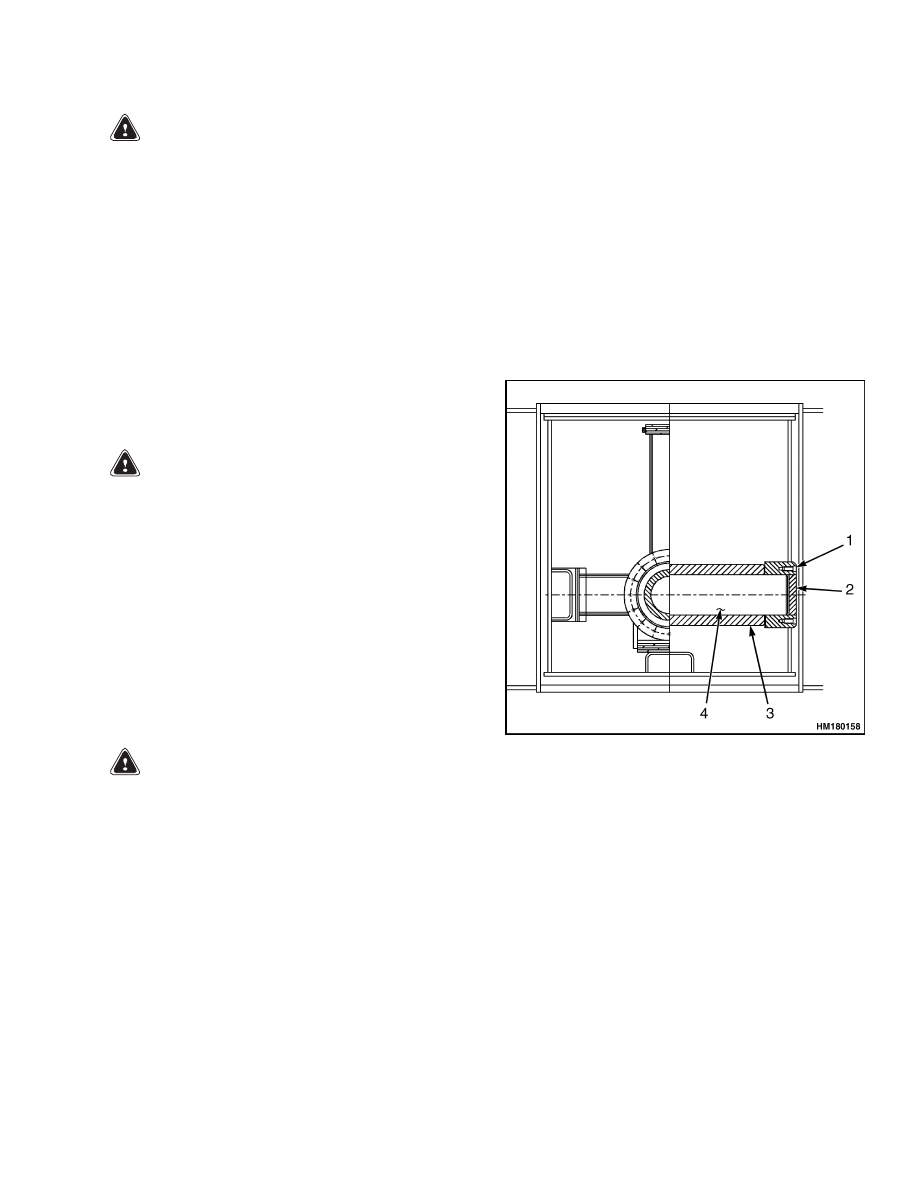
b. Remove the three capscrews and beveled
washers from the locking disc. See Figure 4.
c.
Remove the locking disc.
WARNING
Verify that the dampening cylinder and rotator
frame cannot move.
d. Remove capscrew that holds pin in position.
e.
Use a drift to push the pin out of the boom
and rotator frame hole.
f.
Remove the pin from the other side of the
rotator frame using the same procedure.
g. Remove the spacers, seals, and spherical
bushings from the rotator frame holes.
WARNING
Verify that the lifting device has a capacity of
15,900 kg (35,054 lb) to lift the boom or personal
injury may occur.
9.
Connect a lifting device to the lifting eyes located
at the boom tip. The center of gravity is approx-
imately 3360 mm (132 in.) forward of the pivot
mounts.
1.
SEAL
2.
SPACER
3.
CAPSCREW
4.
BEVELED WASHER
5.
LOCKING DISC
6.
SPACER
7.
SPHERICAL BUSHING
8.
SPACER
9.
PIN
10. SEAL
11. SPACER
Figure 4. Boom to Rotator Frame Mounting up to April 2005
6
4500 SRM 649
Boom Repair
10. Disconnect the lift cylinders from the boom as
follows:
a. Install the special tools to support lift cylin-
ders.
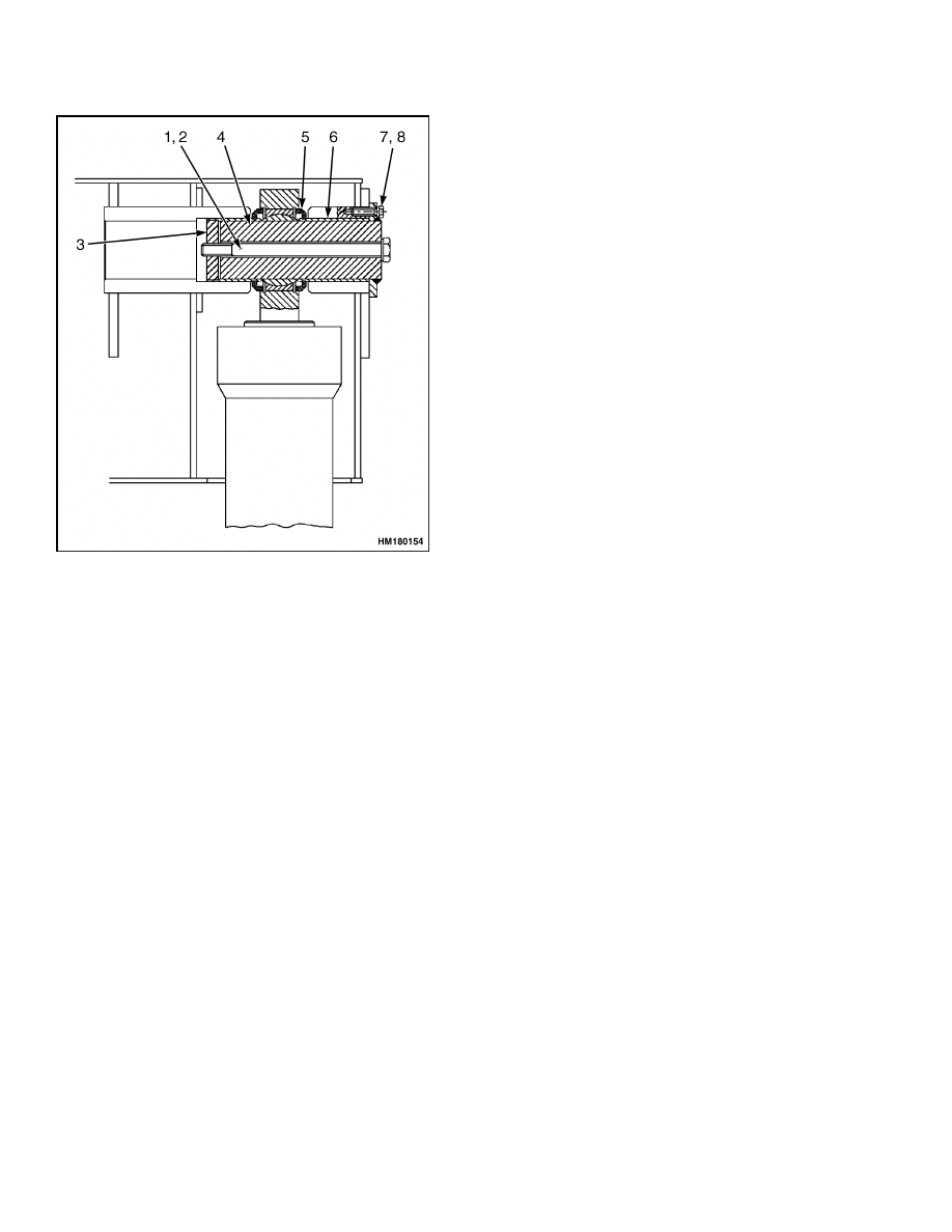
b. Remove the three capscrews for the pivot pin
at the top of the cylinder. SeeFigure 5.
1.
WASHER
2.
TIE ROD
WELDMENT
3.
SPACER
4.
PIN
5.
SEAL
6.
SPACER
7.
CAPSCREW
8.
WASHER
Figure 5. Lift Cylinders to Boom Mounting
c.
Remove the two tie rod weldments.
d. Use capscrews in the threaded holes on the
flange of the pivot pin to pull the pivot pin
out through the spherical bushing.
e.
Use a drift to push the inner spacer in the
boring toward the centerline of the boom.
f.
Remove the outer spacer.
g. Remove the two seals from the spherical
bushing.
h. Remove the pivot pin from the other lift cylin-
der using the same procedure.
i.
Fully retract the lift cylinders.
WARNING
Verify the lifting device has a lifting capacity of
15,900 kg (35,054 lb) to lift the boom or personal
injury may occur.
11. Connect a lifting device to the lifting eyes located
at the back side of the boom. The center of grav-
ity is approximately 3360 mm (132 in.) forward
of the pivot mounts.
12. Disconnect the boom from the frame as follows:
a. Disconnect the two hydraulic lines and three
electrical connectors between the boom and
frame. Put caps on open lines.
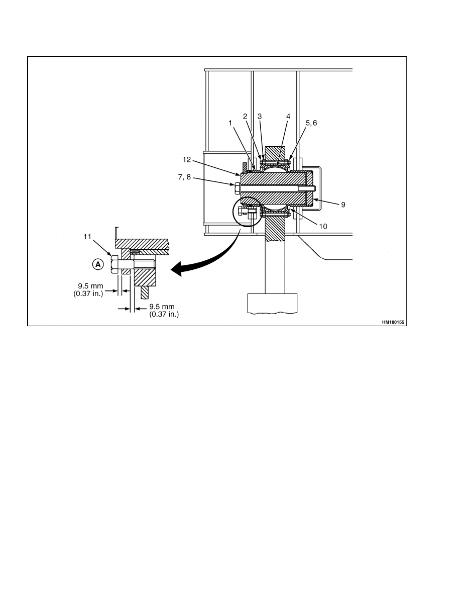
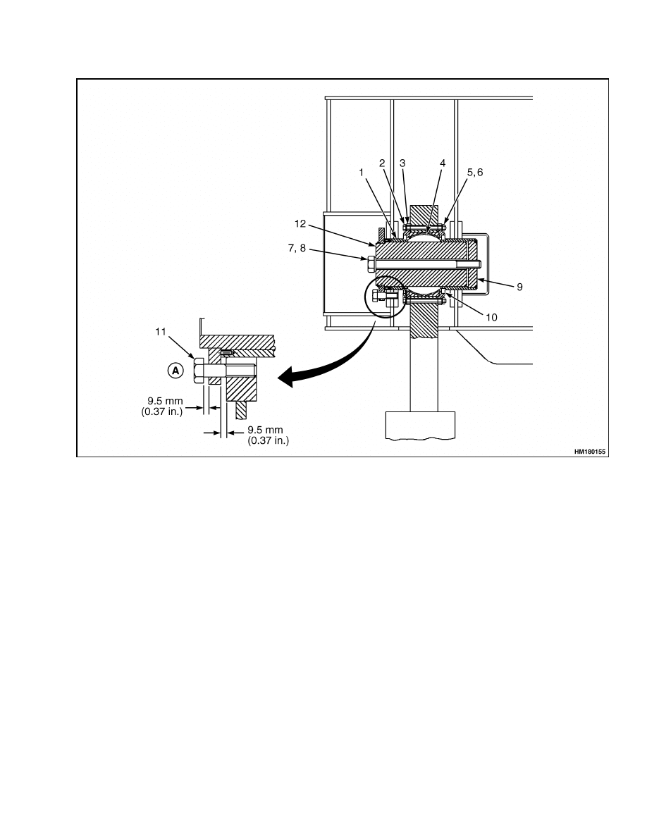
b. Remove the three capscrews of the pivot pin
at the top of the cylinder. See Figure 6.
c.
Remove the two tie rod weldments.
d. Use capscrews in the threaded holes on the
flange of the pivot pin to pull the pivot pin
out through the spherical bushing.
e.
Use a drift to push the inner spacer in the
boring toward the centerline of the boom.
f.
Remove the three flange spacers.
g. Remove the outer spacer from the boom.
h. Remove the pivot pin from the other side of
the boom using the same procedure.
13. Lift the boom assembly from the ReachStacker
and set the boom on supports.
14. Remove the seals from each pivot bushing cover.
15. Remove the capscrews and nuts that hold the
covers on each side of the spherical bushings for
the pivot pins. See Figure 6.
16. Remove the spherical bushings by pushing on the
outer spacer.
17. Remove the inner spacers.
7
Boom Repair
4500 SRM 649
A. THE CAPSCREW SHOULD NOT PROTRUDE.
1.
SPACER
2.
CAPSCREW
3.
COVER
4.
SPHERICAL BUSHING
5.
NUT
6.
WASHER
7.
TIE ROD WELDMENT
8.
WASHER
9.
SPACER
10. SEAL
11. CAPSCREW
12. PIN
Figure 6. Boom to Frame Mounting
Disassemble
1.
Disassemble the extension cylinder as follows:
a. Disconnect the hose support chain from the
support weldment on the left side of the inner
boom section.
b. Put identification tags on the hoses and tubes
at the pilot-assisted, over-center valve at the
rear side of the boom.
c.
Disconnect the hoses and tubes at the pilot-
assisted, over-center valve. Put caps or plugs
in all open fittings.
d. Remove the pilot-assisted, over-center valve
from the extension cylinder.
e.
Remove the two capscrews and beveled
washers and the keeper from the extension
cylinder at the rear side of the boom.
f.
Remove the pin.
8
4500 SRM 649
Boom Repair
g. Connect a lifting device to the inner boom
section.
h. Pull the inner boom section out of the outer
boom section until extension cylinder pin is
out of the outer boom section.
i.
Place the inner boom section on supports.
j.
Remove the six capscrews and two covers
from the extension cylinder at the boom top
side.
k. Remove the pin.
l.
Connect a lifting device to the extension
cylinder.
m. Pull out the extension cylinder from the rear
of the inner boom section.
2.
Remove the adjustment wear caps and wear pads
from the front of the boom by removing the cap-
screws for the wear pads retainers.
3.
Remove the snap rings.
4.
Remove the spherical bushings from the top of
the lift cylinders. See Figure 5.
5.
Remove the spherical bushings by pushing on the
outer spacer.
6.
Disconnect the wiring and indicator lamps only
if there is damage.
Clean and Inspect
WARNING
Cleaning solvents may be flammable and toxic
and can cause severe skin irritation.
When
using cleaning solvents, always follow the
solvent manufacturer’s recommended safety
precautions.
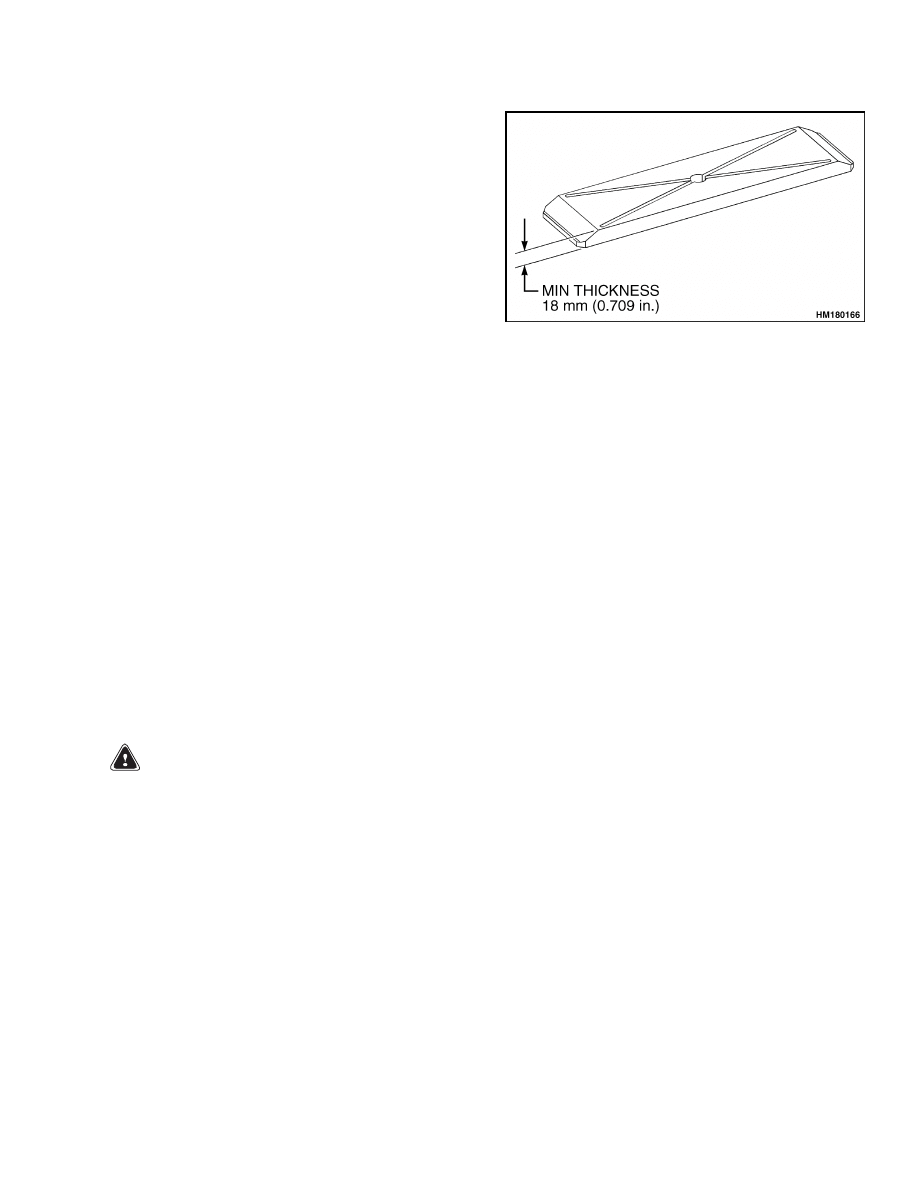
NOTE: When the wearplates have been worn to
a minimum thickness of 18 mm (0.709 in.), the
wearplates must be replaced.
Clean all the parts of the boom section with solvent.
Inspect all the welds for cracks. Inspect the wear
plates and retainers for damaged threads, deep
grooves, or cracks. Check the wear surfaces of the
boom sections. Replace wear plates that are worn.
See Figure 7.
Figure 7. Wearplate
Assemble
1.
If necessary, connect the wiring and indicator
lamps.
2.
Connect a lifting device to the extension cylinder.
3.
Install the extension cylinder into the inner boom
section so the pin tube on the cylinder rod is
aligned with the holes for the mount pin.
4.
Install the pin through the holes into the pin
tube.
5.
Install the two covers.
6.
Apply Loctite
®
270 to the six capscrews and in-
stall the six capscrews.
7.
Connect a lifting device to the inner boom sec-
tion.
8.
Install the two wear plates under the wear plate
retainers and put the assemblies on the lower
inside surface at the front end of the outer boom.
9.
Install the four capscrews and washers in each
retainer at the end of the boom and then install
the capscrew and washer from under the outer
boom into each wear pad retainer.
10. Slide the inner boom section into the outer boom
section so the pin tube on the cylinder shell aligns
with the holes at the rear of the outer boom sec-
tion.
11. Install the pin so the slot for the keeper is at the
top side.
12. Install the keeper, two capscrews, and washers.
Tighten capscrews to 265 N•m (195 lbf ft).
9

Boom Repair
4500 SRM 649
13. Push the inner boom section fully into the outer
boom section and install the wear plate retainer
at the rear of the inner boom section.
14. Apply Loctite
®
270 to the retainer capscrews and
install the wear plate retainer at the rear of the
inner boom section.
15. Install the two wear plates on the upper side of
the inside of the outer boom section.
16. Install the capscrews from the outer end of the
outer boom section.
17. Install the capscrews and washers from the top
of the boom.
18. Install one of the adjustable wear cup assem-
blies, in one of the holes in the sides of the outer
boom section near the front.
19. Loosen the jam nut and turn the adjuster screw
counterclockwise so the retainer is fully against
the boom.
20. Apply Loctite
®
270 to the retainer capscrews. In-
stall and tighten capscrews.
21. Install the other retainer assemblies above and
on the other side of the boom.
22. Adjust each adjuster screw so the inner boom sec-
tion is in the center of the outer boom section.
23. Tighten the jam nuts.
24. Fasten the hose support chain to the support
weldment on the left side of the inner boom
section.
25. Mount the pilot-assisted, over-center valve onto
the extension cylinder in the boom.
26. Attach the hoses to the extension cylinder.
27. Install the hoses and fittings into the pilot-as-
sisted, over-center valve.
28. Install the spherical bushings into the boom
pivot supports.
29. Install the snap rings into the boom pivot sup-
ports.
30. Install the covers with the capscrews and nuts.
Tighten to 79 N•m (58 lbf ft).
31. Install the seals into the covers.
NOTE: Lubricate all of the spacers with molybdenum
disulfide grease before installing into the boom.
32. Install the inner spacer, which has two holes that
are threaded, for the boom pivots at the rear side
of the boom. Push the fully into the bores.
33. Install the outer spacers part way into the bores.
34. Install the inner spacer, which has two holes that
are threaded, for the lift cylinders at the rear side
of the boom. Push them fully into the bores.
35. Install the outer spacers part way into the bores.
36. Install a snap ring into one of the grooves in top
of the lift cylinders.
37. Install the spherical bushing and the other snap
ring in each lift cylinder.
38. Install the snap rings and seals in the top of the
lift cylinders.
39. Install a snap ring into one of the grooves at the
rod end of the dampening cylinder.
40. Install the spherical bushing and the other snap
ring in the dampening cylinder.
Install
1.
Connect a lifting device to lift the boom assembly
at the boom tip and rear side.
2.
Lift and place the boom assembly into position at
the boom tip and rear side.
3.
Connect the boom to the frame as follows:
a. Install the pins so the holes align with the
threaded holes of the inner spacer.
b. Use nuts on two long sections of threaded rod
to pull the inner and outer spacer into the
seals of the bushing.
c.
Pry out the flange enough to install the
flange spacers for each flange capscrew.
d. Rotate the pin weldment so the holes in the
pin flange align with the threaded holes in
the boom.
e.
Install
the
three
capscrews,
washers,
and flange spacers.
Tighten capscrews to
373 N•m (275 lbf ft).
10

4500 SRM 649
Boom Repair
f.
Remove the two long threaded rods.
g. Install two tie rod weldments and tighten to
1216 N•m (897 lbf ft).
4.
Connect the lift cylinder to the boom as follows:
a. Place the boom assembly into position for in-
stalling the pins and carefully align the cen-
ter of the spherical bushing with the center
of the spacers.
b. Install the pins so the holes align with the
threaded holes in the inner spacer.
c.
Use nuts on two long sections of threaded rod
to pull the inner and outer spacer into the
seals of the bushing.
d. Pry out the flange enough to install the
flange spacers for each flange capscrew.
e.
Rotate the pin weldment so the holes in the
pin flange align with the threaded holes in
the boom.
f.
Install
the
three
capscrews,
washers,
and flange spacers.
Tighten capscrews to
373 N•m (275 lbf ft).
g. Remove the two long, threaded rods.
h. Install two tie rod weldments and tighten to
1216 N•m (897 lbf ft).
i.
Remove the special tools for the lift cylinders
from the ReachStacker.
5.
Start the engine.
6.
If the attachment is on a container, drive the
ReachStacker toward the container.
7.
Apply parking brake.
8.
Shut down the engine.
9.
Connect the boom to the rotator frame as follows:
a. Install the spherical bushings in both holes
on the rotator frame so the bushings are in
the center of the holes.
b. Install the seals.
NOTE: Verify that the end of the spacers are toward
the spherical bushing.
NOTE: Lubricate the spacers with molybdenum
disulfide grease before installing.
c.
Install the spacers part way into the yoke.
d. Use the Reachstacker to move the boom into
position for installing the pins and carefully
align the center of the spherical bushings
with the center of the spacers.
e.
Install the pin through the spacers and
spherical bushing.
f.
Install the outer spacer ring on the outer
spacer on each side of the yoke.
g. Install pin weldment so the hole in the pin
flange align with the locking pin in the boom.
h. Install the locking discs with the beveled
washers and capscrews.
i.
Connect the hydraulic lines between the
boom and the rotator frame.
10. Connect the dampening cylinder as follows:
NOTE: Lubricate the pin with molybdenum disulfide
grease before installing.
a. Install the spacers pat way in the pin yoke.
b. Align the rod end of the dampening cylinder
with the pin yoke.
c.
Install the pin so the flat area fits the welded
yoke.
d. Apply Loctite
®
270 to the threads.
e.
Install the locking disc.
f.
Install and tighten the lock ring.
g. Connect the hydraulic lines at the dampen-
ing cylinder.
11. Start the engine and operate the boom functions.
Check that functions of the boom assembly work
correctly as described in the Operating Man-
ual.
12. Operate the hydraulic system until air is out of
the system. Bleed air from system if necessary.
11
Boom Repair
4500 SRM 649
WARNING
Do not try to locate hydraulic leaks by putting
hands on pressurized hydraulic components.
Hydraulic oil can be injected into the body by
pressure.
13. Check for leaks.
MODELS STARTING APRIL 2005
Remove
Repairs to parts of the boom can be made with the
boom installed. Remove the complete boom only if
necessary.
1.
Fully retract the boom.
2.
Place the attachment on a loaded container.
3.
Apply the parking brake.
WARNING
Do not disconnect any hydraulic lines when the
engine is running or personal injury may oc-
cur.
4.
Shut down the engine.
NOTE: Move all control levers back and forth a min-
imum of 20 times to remove all hydraulic pressure
from the pilot system.
5.
Put identification tags on hydraulic lines and
electrical connectors.
6.
Disconnect the two electrical connectors between
the boom and the rotator frame.
7.
Disconnect the dampening cylinder as follows:
a. Put identification tags on the hydraulic lines
during removal.
b. Disconnect the hydraulic lines at the damp-
ening cylinder. Put caps on the open lines.
c.
Disconnect the dampening cylinder at the ro-
tator frame by removing nut from the pin.
See Figure 8.
d. Push the pin through the cylinder head and
frame mounting brackets with a drift.
e.
Remove the pin on the other dampening
cylinder using the same procedure.
1.
PIN
2.
ROTATOR FRAME
3.
DAMPENING CYLINDER
4.
WASHER
5.
NUT
Figure 8. Dampening Cylinder to Rotator
Frame Mounting Starting April 2005
f.
Remove the two spacers.
8.
Disconnect the boom from the rotator frame as
follows:
a. Disconnect the hydraulic lines between the
boom and rotator frame.
Put caps on the
open lines.
b. Remove the lock nut and washer from the
capscrew. See Figure 9.
c.
Use three capscrews in the threaded holes on
the flange of the sliding bushing to pull the
sliding bushing out.
WARNING
Verify that the dampening cylinder and rotator
frame cannot move.
d. Remove capscrew that holds pin in position.
e.
Use a drift to push the pin out of the boom
and rotator frame hole.
f.
Remove the pin from the other side of the
rotator frame using the same procedure.
12
4500 SRM 649
Boom Repair
1.
BUSHING
2.
WASHER
3.
LOCK NUT
4.
SLIDING BUSHING
5.
PIN
6.
FIXED BUSHING
7.
CAPSCREW
Figure 9. Boom to Rotator Frame Mounting Starting April 2005
g. Remove the bushings from the boom holes.
WARNING
Verify that the lifting device has a capacity of
15,900 kg (35,054 lb) to lift the boom or personal
injury may occur.
9.
Connect a lifting device to the lifting eyes located
at the boom tip. The center of gravity is approx-
imately 3360 mm (132 in.) forward of the pivot
mounts.
10. Disconnect the lift cylinders from the boom as
follows:
a. Install the special tools to support lift cylin-
ders.
b. Remove the three capscrews for the pivot pin
at the top of the cylinder. SeeFigure 10.
c.
Remove the two tie rod weldments.
d. Use capscrews in the threaded holes on the
flange of the pivot pin to pull the pivot pin
out through the spherical bushing.
e.
Use a drift to push the inner spacer in the
boring toward the centerline of the boom.
f.
Remove the outer spacer.
g. Remove the two seals from the spherical
bushing.
h. Remove the pivot pin from the other lift cylin-
der using the same procedure.
i.
Fully retract the lift cylinders.
WARNING
Verify the lifting device has a lifting capacity of
15,900 kg (35,054 lb) to lift the boom or personal
injury may occur.
11. Connect a lifting device to the lifting eyes located
at the back side of the boom. The center of grav-
ity is approximately 3360 mm (132 in.) forward
of the pivot mounts.
13
Boom Repair
4500 SRM 649
1.
WASHER
2.
TIE ROD
WELDMENT
3.
SPACER
4.
PIN
5.
SEAL
6.
SPACER
7.
CAPSCREW
8.
WASHER
Figure 10. Lift Cylinders to Boom Mounting
12. Disconnect the boom from the frame as follows:
a. Disconnect the two hydraulic lines and three
electrical connectors between the boom and
frame. Put caps on open lines.
b. Remove the three capscrews of the pivot pin
at the top of the cylinder. See Figure 11.
c.
Remove the two tie rod weldments.
d. Use capscrews in the threaded holes on the
flange of the pivot pin to pull the pivot pin
out through the spherical bushing.
e.
Use a drift to push the inner spacer in the
boring toward the centerline of the boom.
f.
Remove the three flange spacers.
g. Remove the outer spacer from the boom.
h. Remove the pivot pin from the other side of
the boom using the same procedure.
13. Lift the boom assembly from the ReachStacker
and set the boom on supports.
14. Remove the seals from each pivot bushing cover.
15. Remove the capscrews and nuts that hold the
covers on each side of the spherical bushings for
the pivot pins. See Figure 11.
16. Remove the spherical bushings by pushing on the
outer spacer.
17. Remove the inner spacers.
Disassemble
1.
Disassemble the extension cylinder as follows:
a. Disconnect the hose support chain from the
support weldment on the left side of the inner
boom section.
b. Put identification tags on the hoses and tubes
at the pilot-assisted, over-center valve at the
rear side of the boom.
c.
Disconnect the hoses and tubes at the pilot-
assisted, over-center valve. Put caps or plugs
in all open fittings.
d. Remove the pilot-assisted, over-center valve
from the extension cylinder.
e.
Remove the two capscrews and beveled
washers and the keeper from the extension
cylinder at the rear side of the boom.
f.
Remove the pin.
g. Connect a lifting device to the inner boom
section.
h. Pull the inner boom section out of the outer
boom section until extension cylinder pin is
out of the outer boom section.
i.
Place the inner boom section on supports.
j.
Remove the six capscrews and two covers
from the extension cylinder at the boom top
side.
k. Remove the pin.
l.
Connect a lifting device to the extension
cylinder.
14
4500 SRM 649
Boom Repair
A. THE CAPSCREW SHOULD NOT PROTRUDE.
1.
SPACER
2.
CAPSCREW
3.
COVER
4.
SPHERICAL BUSHING
5.
NUT
6.
WASHER
7.
TIE ROD WELDMENT
8.
WASHER
9.
SPACER
10. SEAL
11. CAPSCREW
12. PIN
Figure 11. Boom to Frame Mounting
m. Pull out the extension cylinder from the rear
of the inner boom section.
2.
Remove the adjustment wear caps and wear pads
from the front of the boom by removing the cap-
screws for the wear pads retainers.
3.
Remove the snap rings.
4.
Remove the spherical bushings from the top of
the lift cylinders. See Figure 10.
5.
Remove the spherical bushings by pushing on the
outer spacer.
6.
Disconnect the wiring and indicator lamps only
if there is damage.
15

Boom Repair
4500 SRM 649
Clean and Inspect
WARNING
Cleaning solvents may be flammable and toxic
and can cause severe skin irritation.
When
using cleaning solvents, always follow the
solvent manufacturer’s recommended safety
precautions.
NOTE: When the wearplates have been worn to
a minimum thickness of 18 mm (0.708 in.), the
wearplates must be replaced.
Clean all the parts of the boom section with solvent.
Inspect all the welds for cracks. Inspect the wear
plates and retainers for damaged threads, deep
grooves, or cracks. Check the wear surfaces of the
boom sections. Replace wear plates that are worn.
Assemble
1.
If necessary, connect the wiring and indicator
lamps.
2.
Connect a lifting device to the extension cylinder.
3.
Install the extension cylinder into the inner boom
section so the pin tube on the cylinder rod is
aligned with the holes for the mount pin.
4.
Install the pin through the holes into the pin
tube.
5.
Install the two covers.
6.
Apply Loctite
®
270 to the six capscrews and in-
stall the six capscrews.
7.
Connect a lifting device to the inner boom sec-
tion.
8.
Install the two wear plates under the wear plate
retainers and put the assemblies on the lower
inside surface at the front end of the outer boom.
9.
Install the four capscrews and washers in each
retainer at the end of the boom and then install
the capscrew and washer from under the outer
boom into each wear pad retainer.
10. Slide the inner boom section into the outer boom
section so the pin tube on the cylinder shell aligns
with the holes at the rear of the outer boom sec-
tion.
11. Install the pin so the slot for the keeper is at the
top side.
12. Install the keeper, two capscrews, and washers.
Tighten capscrews to 265 N•m (195 lbf ft).
13. Push the inner boom section fully into the outer
boom section and install the wear plate retainer
and two wear plates on top of the inner boom
section.
14. Apply Loctite
®
270 to the retainer capscrews and
install the wear plate retainer at the rear of the
inner boom section.
15. Install the two wear plates on the upper side of
the inside of the outer boom section.
16. Install the capscrews from the outer end of the
outer boom section.
17. Install the capscrews and washers from the top
of the boom.
18. Install one of the adjustable wear cup assem-
blies, in one of the holes in the sides of the outer
boom section near the front.
19. Loosen the jam nut and turn the adjuster screw
counterclockwise so the retainer is fully against
the boom.
20. Apply Loctite
®
270 to the retainer capscrews. In-
stall and tighten capscrews.
21. Install the other retainer assemblies above and
on the other side of the boom.
22. Adjust each adjuster screw so the inner boom sec-
tion is in the center of the outer boom section.
23. Tighten the jam nuts.
24. Fasten the hose support chain to the support
weldment on the left side of the inner boom
section.
25. Mount the pilot-assisted, over-center valve onto
the extension cylinder in the boom.
26. Attach the hoses to the extension cylinder.
27. Install the hoses and fittings into the pilot-as-
sisted, over-center valve.
16

4500 SRM 649
Boom Repair
28. Install the spherical bushings into the boom
pivot supports.
29. Install the snap ring into the boom pivot sup-
ports.
30. Install the covers with the capscrews and nuts.
Tighten to 79 N•m (58 lbf ft).
31. Install the seals into the covers.
NOTE: Lubricate all of the spacers with molybdenum
disulfide grease before installing into the boom.
32. Install the inner spacer, which has two holes that
are threaded, for the boom pivots at the rear side
of the boom. Push the fully into the bores.
33. Install the outer spacers part way into the bores.
34. Install the inner spacer, which has two holes that
are threaded, for the lift cylinders at the rear side
of the boom. Push them fully into the bores.
35. Install the outer spacers part way into the bores.
36. Install a snap ring into one of the grooves in top
of the lift cylinders.
37. Install the spherical bushing and the other snap
ring in each lift cylinder.
38. Install the snap rings and seals in the top of the
lift cylinders.
39. Install a snap ring into one of the grooves at the
rod end of the dampening cylinder.
40. Install the spherical bushing and the other snap
ring in the dampening cylinder.
Install
1.
Connect a lifting device to lift the boom assembly
at the boom tip and rear side.
2.
Lift and place the boom assembly into position for
installing the pins and carefully align the center
of the spherical bushing with the center of the
spacer tubes.
3.
Connect the boom to the frame as follows:
a. Install the pins so the holes align with the
threaded holes of the inner spacer.
b. Use nuts on two long sections of threaded rod
to pull the inner and outer spacer into the
seals of the bushing.
c.
Pry out the flange enough to install the
flange spacers for each flange capscrew.
d. Rotate the pin weldment so the holes in the
pin flange align with the threaded holes in
the boom.
e.
Install
the
three
capscrews,
washers,
and flange spacers.
Tighten capscrews to
373 N•m (275 lbf ft).
f.
Remove the two long, threaded rods.
g. Install two tie rod weldments and tighten to
1216 N•m (897 lbf ft).
4.
Connect the lift cylinder to the boom as follows:
a. Place the boom assembly into position for in-
stalling the pins and carefully align the cen-
ter of the spherical bushing with the center
of the spacers.
b. Install the pins so the holes align with the
threaded holes in the inner spacer.
c.
Use nuts on two long sections of threaded rod
to pull the inner and outer spacer into the
seals of the bushing.
d. Pry out the flange enough to install the
flange spacers for each flange capscrew.
e.
Rotate the pin weldment so the holes in the
pin flange align with the threaded holes in
the boom.
f.
Install
the
three
capscrews,
washers,
and flange spacers.
Tighten capscrews to
373 N•m (275 lbf ft).
g. Remove the two long, threaded rods.
h. Install two tie rod weldments and tighten to
1216 N•m (897 lbf ft).
i.
Remove the special tools for the lift cylinders
from the ReachStacker.
5.
Start the engine.
6.
If the attachment is on a container, drive the
ReachStacker toward the container.
17

Dampening Cylinder Repair
4500 SRM 649
7.
Apply parking brake.
8.
Shut down the engine.
9.
Connect the boom to the rotator frame as follows:
a. Install the bushings in both holes on the
boom so the bushings are in the center of the
holes.
b. Use the ReachStacker to move the boom into
position for installing the pins and carefully
align the center of the bushings with the cen-
ter of the rotator frame holes.
c.
Install the pin and fixed bushing from the
outside toward the center of the rotator
frame.
d. Install the capscrew.
e.
Install the sliding bushing.
f.
Install the washer and lock nut on the cap-
screw and tighten to 320 N•m (236 lbf ft).
g. Connect the hydraulic lines between the
boom and the rotator frame.
10. Connect the dampening cylinder as follows:
NOTE: Lubricate the pin with molybdenum disulfide
grease before installing.
a. Align the rod end of the dampening cylinder
with the pin yoke.
b. Push the pin partway in the dampening
cylinder head from the outside towards the
center of the rotator frame.
c.
Install the spacer and push the pin com-
pletely through the dampening cylinder
head.
d. Install the nut and tighten.
e.
Install the pin on the other dampening cylin-
der using the same procedure.
f.
Connect the hydraulic lines at the dampen-
ing cylinder.
11. Start the engine and operate the boom functions.
Check that functions of the boom assembly work
correctly as described in the Operating Man-
ual.
12. Operate the hydraulic system until air is out of
the system. Bleed air from system if necessary.
WARNING
Do not try to locate hydraulic leaks by putting
hands on pressurized hydraulic components.
Hydraulic oil can be injected into the body by
pressure.
13. Check for leaks.
Dampening Cylinder Repair
MODELS UP TO APRIL 2005
Remove
1.
Place the Reachstacker on a solid, level surface.
2.
Fully lower and retract the boom.
3.
Apply the parking brake.
WARNING
Do not disconnect any hydraulic lines when the
engine is running or personal injury may oc-
cur.
4.
Shut down the engine.
NOTE: Move all control levers back and forth a min-
imum of 20 times to remove all hydraulic pressure
from the pilot system.
5.
Put identification tags on the lines during re-
moval.
6.
Disconnect the hydraulic lines at the dampening
cylinder. Put caps on the open lines.
7.
Disconnect the dampening cylinder at the rotator
frame by removing the lock ring from the pin. See
Figure 3.
8.
Disconnect the dampening cylinder at the rota-
tor frame by removing nut from the pin. See Fig-
ure 8.
18
4500 SRM 649
Dampening Cylinder Repair
9.
Push the pin through the spherical bushing in
the rod end with a drift.
10. Push the pin through the cylinder head and
frame mounting brackets with a drift.
WARNING
Verify that the lifting device has the rated ca-
pacity to lift the dampening cylinder or per-
sonal injury may occur.
11. Connect a lifting device to the dampening cylin-
der.
12. Remove the 12 capscrews from the left and right
flange at the boom tip. See Figure 12.
1.
DAMPENING
CYLINDER
2.
WASHER
3.
CAPSCREW
4.
LUBE FITTING
5.
FLANGE
6.
BUSHING
Figure 12. Dampening Cylinder to Boom
Mounting
13. Remove the left and right flange.
14. Remove the bushings positioned in the holes of
the boom tip.
15. Remove the dampening cylinder from the rotator
frame and boom tip.
Disassemble
1.
Put the dampening cylinder in a vise with soft
jaws, placed in a horizontal position.
2.
Remove the four capscrews from the rod eye. See
Figure 13.
3.
Remove the rod eye from the piston rod by turn-
ing the rod eye counterclockwise.
4.
Remove the sleeve from the piston rod by turning
the sleeve counterclockwise.
CAUTION
Use caution not to damage the finished surface
of the piston rod when removing the piston rod
from the cylinder shell in a horizontal position
(parallel with the cylinder shell).
5.
Disassemble piston rod assembly from the cylin-
der shell by pulling it out.
6.
Remove the capscrews from the cylinder.
7.
Remove the cylinder from the cylinder shell.
8.
If necessary, remove the piston from the piston
rod.
CAUTION
Use caution not to damage the grooves when
removing seals and rings.
9.
Disassemble and remove all seals and rings.
19
Dampening Cylinder Repair
4500 SRM 649
Figure 13. Dampening Cylinder
20
4500 SRM 649
Dampening Cylinder Repair
Legend for Figure 13
1.
FITTING
2.
ROD EYE
3.
CAPSCREW
4.
SNAP RING
5.
SLEEVE
6.
PISTON ROD
7.
TUBE
8.
PISTON
9.
CYLINDER
10. CAPSCREW
11. WASHER
12. SNAP RING
13. BEARING
14. CAPSCREW
15. RING
16. RING
17. SEAL
18. SEAL
19. RING
20. SEAL
21. RING
22. SEAL
23. RING
24. SEAL
Clean
WARNING
Cleaning solvents may be flammable and toxic
and can cause severe skin irritation.
When
using cleaning solvents, always follow the
solvent manufacturer’s recommended safety
precautions.
WARNING
Compressed air can move particles so that they
cause injury to the user or to other personnel.
Make sure the path of the compressed air is
away from all personnel. Wear protective gog-
gles or a face shield to prevent injury to the
eyes.
Clean all parts with solvent and remove residual sol-
vent or allow the solvent to evaporate.
Inspect
Inspect the parts of the dampening cylinder for dam-
age, rust, or wear. Carefully inspect the rod sur-
faces for dents and scratches. Verify that the internal
stroke surfaces of the cylinder shell and the grooves
for the seals do not show any nicks, scratches, or
other damage. Repair or replace parts as needed.
Assemble
NOTE: Verify that all parts are clean before assembly.
NOTE: Always use new seals. Lubricate all parts
with clean hydraulic oil.
1.
If necessary, assemble the piston into the piston
rod.
2.
Assemble the new seals and rings on the piston
rod and in the cylinder.
3.
Assemble the cylinder to the cylinder shell with
the capscrews. Tightly fasten the capscrews.
CAUTION
Be careful not to damage the finished surface
of the piston rod when installing the piston rod
into the cylinder shell in a horizontal position
(parallel to the cylinder shell).
4.
Lubricate the cylinder shell bore with clean hy-
draulic oil. Push the piston rod assembly into the
cylinder shell and through the cylinder.
NOTE: No special torque is required when tightening
the sleeve. Tightly fasten the sleeve.
5.
Lubricate the thread of the sleeve and assemble
the sleeve into the cylinder shell by turning clock-
wise. Fasten the sleeve.
6.
Assemble the rod eye onto the piston rod by turn-
ing clockwise.
7.
Install the four capscrews that hold the rod eye
onto the piston rod.
Install
WARNING
Verify that the lifting device has the rated ca-
pacity to lift the dampening cylinder or per-
sonal injury may occur.
1.
Use a lifting device to put the dampening cylin-
der in position.
2.
Install the bushings in the holes of the boom tip.
3.
Install the left and right flange into the holes of
the boom tip and over the bushings.
21
Dampening Cylinder Repair
4500 SRM 649
4.
Install the capscrews that hold the left and right
flange.
5.
Install the pin through the spherical bushing at
the rod end and keep the spacers in place.
6.
Install the locking disc and lock ring at the other
side of the pin by turning clockwise.
7.
Connect the hydraulic lines as tagged during re-
moval.
8.
Start the engine and operate the dampening
cylinder.
Verify that the dampening cylinder
functions correctly.
WARNING
Do not try to locate hydraulic leaks by placing
hands on pressurized hydraulic components.
Hydraulic oil can be injected into the body by
pressure.
9.
Check for leaks.
MODELS STARTING APRIL 2005
Remove
1.
Place the Reachstacker on a solid, level surface.
2.
Fully lower and retract the boom.
3.
Apply the parking brake.
WARNING
Do not disconnect any hydraulic lines when the
engine is running or personal injury may oc-
cur.
4.
Shut down the engine.
NOTE: Move all control levers back and forth a min-
imum of 20 times to remove all hydraulic pressure
from the pilot system.
5.
Put identification tags on the lines during re-
moval.
6.
Disconnect the hydraulic lines at the dampening
cylinder. Put caps on the open lines.
7.
Disconnect the dampening cylinder at the rota-
tor frame by removing nut from the pin. See Fig-
ure 8.
8.
Push the pin through the cylinder head and
frame mounting brackets with a drift.
WARNING
Verify that the lifting device has the rated ca-
pacity to lift the dampening cylinder or per-
sonal injury may occur.
9.
Connect a lifting device to the dampening cylin-
der.
10. Remove the nut and washer from the pin. See
1.
PIN
2.
BALL JOINT
3.
INNER BOOM
(BOOM TIP)
4.
WASHER
5.
NUT
6.
SPACER
7.
DAMPENING
CYLINDER
Figure 14. Dampening Cylinder to Boom
Mounting
11. Push the pin through the cylinder holes and
boom mounting bracket with a drift.
12. Remove the spacer and ball joint from the boom
mounting bracket hole.
13. Remove the dampening cylinder from the rotator
frame and boom tip.
14. Remove the pin on the other dampening cylinder
using the same procedure.
22
4500 SRM 649
Dampening Cylinder Repair
Disassemble
1.
Put the dampening cylinder in a vise with soft
jaws, placed in a horizontal position.
2.
Disassemble the gland using a pin wrench to un-
screw the gland. See Figure 15.
CAUTION
Use caution not to damage the finished surface
of the piston rod when removing the piston rod
from the cylinder shell in a horizontal position
(parallel with the cylinder shell).
3.
Disassemble the piston rod by pulling it out of
the cylinder shell.
CAUTION
Be careful not to damage the grooves when re-
moving seals and rings.
4.
Disassemble and remove the piston.
5.
Loosen the setscrew on the nut and remove the
nut.
6.
Remove the piston and the gland.
7.
Remove all seals from the gland and piston.
1.
PISTON ROD
2.
SEAL KIT
3.
GLAND
4.
PISTON
5.
NUT
6.
SETSCREW
7.
SHELL
8.
SNAP RING
9.
BALL JOINT
10. GREASE NIPPLE
Figure 15. Dampening Cylinder
23
Dampening Cylinder Repair
4500 SRM 649
Clean
WARNING
Cleaning solvents may be flammable and toxic
and can cause severe skin irritation.
When
using cleaning solvents, always follow the
solvent manufacturer’s recommended safety
precautions.
WARNING
Compressed air can move particles so that they
cause injury to the user or to other personnel.
Make sure the path of the compressed air is
away from all personnel. Wear protective gog-
gles or a face shield to prevent injury to the
eyes.
Clean all parts with solvent and remove residual sol-
vent or allow the solvent to evaporate.
Inspect
Inspect the parts of the dampening cylinder for dam-
age, rust, or wear. Carefully inspect the rod sur-
faces for dents and scratches. Verify that the internal
stroke surfaces of the cylinder shell and the grooves
for the seals do not show any nicks, scratches, or
other damage. Repair or replace parts as needed.
Assemble
NOTE: Verify that all parts are clean before assembly.
NOTE: Always use new seals. Lubricate all parts
with clean hydraulic oil.
1.
Assemble new seals on the piston and gland.
2.
Assemble the gland on the piston rod.
3.
Using the nut and setscrew, assemble the piston
on the piston rod. Tightly fasten the nut and fix
with the setscrew.
CAUTION
Use caution not to damage the finished surface
of the piston rod when installing the piston rod
into the cylinder shell in a horizontal position
(parallel to the cylinder shell).
4.
Lubricate the cylinder shell bore with clean hy-
draulic oil. Put the piston rod assembly into the
cylinder shell.
NOTE: No special torque is required when tightening
the gland. Tightly fasten the gland.
5.
Lubricate the thread of the gland, and screw the
gland into the cylinder shell. Fasten the gland.
Install
WARNING
Verify that the lifting device has the rated ca-
pacity to lift the dampening cylinder or per-
sonal injury may occur.
1.
Install the ball joint in the boom mounting
bracket holes.
2.
Use a lifting device to put the dampening cylin-
der in position.
3.
Install the pin from the outside toward the center
of the rotator frame.
4.
Install the washer and nut and tighten.
5.
Align the rod end of the dampening cylinder with
the pin yoke.
6.
Push the pin partway in the dampening cylinder
head from the outside toward the center of the
rotator frame.
7.
Install the spacer and push the pin completely
through the dampening cylinder head.
8.
Install the nut and tighten.
9.
Install the pin on the other dampening cylinder
using the same procedure.
10. Connect the hydraulic lines at the dampening
cylinders as tagged during removal.
11. If power dampening is available, start the en-
gine and operate the dampening cylinders.
Check that functions of the dampening cylinders
work correctly.
12. If power dampening is NOT available, start the
engine and operate the boom up and down to ver-
ify all air is out of the dampening cylinders.
24
4500 SRM 649
Extension Cylinder Repair
WARNING
Do not try to locate hydraulic leaks by placing
hands on pressurized hydraulic components.
Hydraulic oil can be injected into the body by
pressure.
13. Check for leaks.
Extension Cylinder Repair
REMOVE
1.
Place the ReachStacker
®
on a solid, level surface.
2.
Fully lower the boom.
3.
Retract the boom and stop about 1.5 m (4.92 ft)
before fully retracting, still having access to the
extension pin located in the inner boom section.
4.
Apply the parking brake.
WARNING
Do not disconnect any hydraulic lines while
the engine is running or personal injury may
occur.
5.
Shut down the engine.
NOTE: Move all control levers back and forth a min-
imum of 20 times to remove all hydraulic pressure
from pilot system.
6.
Disconnect the extension cylinder at the inner
boom section by removing the six capscrews and
left and right cover from the pin. See Figure 16.
7.
Push the pin through the hole with a drift.
WARNING
Verify that the lifting device has the rated ca-
pacity to lift the dampening cylinder or per-
sonal injury may occur.
8.
Connect a lifting device to the extension cylinder.
9.
Put identification tags on the hoses and tubes at
the pilot-assisted, over-center valve at the rear of
the boom.
10. Disconnect the hoses and tubes from the pilot-
assisted, over-center valve. Put caps or plugs in
open fittings.
11. Remove the pilot-assisted, over-center valve
from the extension cylinder.
12. Remove the two capscrews, beveled washers, and
the keeper from the extension cylinder.
13. Push the pin through the hole with a drift.
14. Pull out the extension cylinder from the rear of
the outer boom section.
1.
CAPSCREW
2.
COVER
3.
EXTENSION CYLINDER
4.
PIN
Figure 16. Extension Cylinder to Inner Boom
Mounting
DISASSEMBLE
1.
Place the entire cylinder on a support that is long
enough to support the cylinder in a horizontal
position.
2.
Drain the remaining hydraulic oil out of the ex-
tension cylinder.
3.
Remove the capscrews from the extension cylin-
der. See Figure 17.
25
Extension Cylinder Repair
4500 SRM 649
Figure 17. Extension Cylinder
26
4500 SRM 649
Extension Cylinder Repair
Legend for Figure 17
1.
TUBE
2.
PISTON HOSE
3.
PISTON ROD
4.
CYLINDER
5.
TUBE
6.
PISTON
7.
PLATE
8.
PLATE GUIDE
9.
SCREW
10. SCREW
11. CAPSCREW
12. WASHER
13. PLUG
14. RING
15. RING
16. SEAL
17. RING
18. RING
19. SEAL
20. RING
21. SEAL
22. SEAL
23. RING
24. SEAL
25. RING
26. RING
27. PISTON HEAD
CAUTION
Be careful not to damage the finished surface
of the piston hose when removing the piston
hose from the cylinder shell in a horizontal po-
sition (parallel with the cylinder shell).
4.
Disassemble the piston hose assembly from the
cylinder shell by pulling it out.
5.
Disassemble and remove the piston from the pis-
ton hose.
6.
Remove the screws on the piston head.
7.
Remove the piston head from the piston hose by
turning the piston head counterclockwise.
8.
Remove the cylinder and piston rod from the pis-
ton hose.
CAUTION
Be careful not to damage the grooves when re-
moving seals and rings.
9.
Disassemble and remove all seals and rings.
CLEAN
WARNING
Cleaning solvents may be flammable and toxic
and can cause severe skin irritation.
When
using cleaning solvents, always follow the
solvent manufacturer’s recommended safety
precautions.
WARNING
Compressed air can move particles so that they
cause injury to the user or to other personnel.
Make sure the path of the compressed air is
away from all personnel. Wear protective gog-
gles or a face shield to prevent injury to the
eyes.
Clean all parts in solvent and remove residual sol-
vent or allow the solvent to evaporate.
INSPECT
Inspect the parts of the extension cylinder for dam-
age, rust, or wear. Carefully inspect the rod sur-
faces for dents and scratches. Verify that the internal
stroke surfaces of the cylinder shell and the grooves
for the seals do not show any nicks, scratches, or
other damage. Repair or replace parts as needed.
ASSEMBLE
NOTE: Verify that all parts are clean before assembly.
NOTE: Always use new seals. Lubricate all parts
with clean hydraulic oil.
1.
Assemble the new seals and rings on the cylinder
and piston rod.
2.
Assemble the piston, piston rod, and cylinder on
the piston hose.
CAUTION
Be careful not to damage the finished surface
of the piston hose when installing the piston
hose into the cylinder shell in a horizontal po-
sition (parallel to the cylinder shell).
3.
Lubricate the cylinder shell bore with clean hy-
draulic oil. Put the piston hose assembly into the
cylinder shell.
4.
Assemble the cylinder onto the cylinder shell
with 20 capscrews and tightly fasten the cap-
screws.
5.
Assemble the piston head on the piston hose by
turning the piston head clockwise.
6.
Tighten the piston head using the screws.
27

Lift Cylinders Repair
4500 SRM 649
INSTALL
1.
Connect a lifting device to the extension cylinder.
2.
Install the extension cylinder in the inner boom
section (through the rear of the outer boom sec-
tion) so the pin tube on the cylinder rod is aligned
with the holes for the mount pin.
3.
Install the pin through the holes into the pin tube
at the cylinder rod side.
4.
Install the two covers.
5.
Apply Loctite
®
270 to the six capscrews and in-
stall capscrews.
6.
Align the pin tube on the cylinder shell with the
holes at the rear of the outer boom section.
7.
Install the pin so the slot for the keeper is at the
top side.
8.
Install the keeper, two capscrews, and washers.
Tighten the capscrews to 265 N•m (195 lbf ft).
9.
Mount the pilot-assisted, over-center valve onto
the extension cylinder in the boom.
10. Attach the hoses to the extension cylinder.
11. Install the hoses and fittings into the pilot-as-
sisted, over-center valve.
12. Start the engine and operate the boom functions.
Verify that the extension cylinder functions cor-
rectly.
WARNING
Do not try to locate hydraulic leaks by placing
hands on pressurized hydraulic components.
Hydraulic oil can be injected into the body by
pressure.
13. Check for leaks.
Lift Cylinders Repair
REMOVE
1.
Place the ReachStacker on a solid level surface.
2.
Raise the boom approximately 1 m (3.3 ft) and set
the attachment on a container. This will allow
removal of the lift cylinders.
3.
Apply the parking brake.
WARNING
Do not disconnect any hydraulic lines when the
engine is running or personal injury may oc-
cur.
4.
Shut down the engine.
5.
Install two lifting eyes to the lift cylinders.
6.
Install the special tool to support the lift cylinder
for removal.
7.
Remove the three capscrews for the pivot pin at
the top of the lift cylinder. See Figure 5.
8.
Remove the two tie rod weldments.
9.
Use two capscrews in the threaded holes on the
flange of the pivot pin to pull the pivot pin out
through the spherical bushing.
10. Use a drift to push the inner spacer in the boring
toward the centerline of the boom.
11. Remove the outer spacer.
12. Remove the two seals from the spherical bushing.
13. Remove the two snap rings.
14. Remove the spherical bushing by pushing on the
outer spacer.
15. Follow Step 5 through Step 14 to remove the
pivot pin of the other lift cylinder.
16. Fully retract the lift cylinders.
17. Put identification tags on hydraulic lines.
NOTE: Move all control levers back and forth a min-
imum of 20 times to remove all hydraulic pressure
from pilot system.
18. Disconnect the hydraulic lines at the lift cylinder.
28
4500 SRM 649
Lift Cylinders Repair
WARNING
Verify the lifting device has a lifting capacity
of 1,000 kg (2,205 lb) to lift the lift cylinder or
personal injury may occur.
19. Connect a lifting device to the lifting eyes on the
lift cylinder.
20. Remove the three capscrews and beveled wash-
ers from the cap at the frame. See Figure 18.
21. Remove the cap.
22. Remove the capscrew that holds the pin in posi-
tion.
23. Use capscrews in the two threaded holes on the
flange of the pivot pin to pull the pivot pin out
through the spherical bushing.
24. Remove the two spacers.
25. Remove the two seals from the spherical bushing.
26. Remove the two snap rings.
27. Remove the spherical bushing by pushing on the
outer race.
28. Remove the lift cylinder from the ReachStacker.
29. Remove the special tool from the ReachStacker.
30. If necessary, remove the other lift cylinder using
the same procedure.
DISASSEMBLE
1.
Place the entire cylinder on a support that is long
enough to support the cylinder in a horizontal
position.
2.
Drain the remaining hydraulic oil out of the lift
cylinder.
3.
Disassemble the guide using a pin wrench to un-
screw the guide counterclockwise. See Figure 19.
CAUTION
Be careful not to damage the finished surface
of the piston rod when installing the piston rod
into the cylinder shell in a horizontal position
(parallel to the cylinder shell).
4.
Disassemble the piston rod assembly from the
cylinder shell by pulling it out.
1.
LIFT CYLINDER
2.
KEEPER
3.
CAP
4.
SPACER
5.
SEAL
6.
SPHERICAL BUSHING
7.
SNAP RING
8.
BEVELED WASHER
9.
CAPSCREW
10. WASHER
11. LOCKWASHER
12. CAPSCREW
Figure 18. Lift Cylinder to Frame Mounting
29
Lift Cylinders Repair
4500 SRM 649
Figure 19. Lift Cylinder
30
4500 SRM 649
Lift Cylinders Repair
Legend for Figure 19
1.
LIFTING EYE
2.
PISTON
3.
CAPSCREW
4.
WASHER
5.
TUBE
6.
PISTON ROD
7.
GUIDE
8.
SNAP RING
9.
ROD EYE
10. SET SCREW
11. PLUG
12. PLUG
13. RING
14. SEAL
15. SEAL
16. RING
17. O-RING
18. RING
19. O-RING
20. RING
21. SEAL
22. O-RING
23. RING
24. O-RING
25. RING
26. RING
5.
Disassemble and remove the piston.
6.
Remove the two setscrews on the rod eye.
7.
Remove the rod eye from the piston rod by turn-
ing the piston rod counterclockwise.
8.
Remove the guide from the piston rod.
CAUTION
Be careful not to damage the grooves when re-
moving seals and rings.
9.
Disassemble and remove all seals and rings.
CLEAN
WARNING
Cleaning solvents may be flammable and toxic
and can cause severe skin irritation.
When
using cleaning solvents, always follow the
solvent manufacturer’s recommended safety
precautions.
WARNING
Compressed air can move particles so that they
cause injury to the user or to other personnel.
Make sure the path of the compressed air is
away from all personnel. Wear protective gog-
gles or a face shield to prevent injury to the
eyes.
Clean all parts with solvent and remove residual sol-
vent or allow the solvent to evaporate.
INSPECT
Inspect the parts of the lift cylinder for damage, rust,
or wear. Carefully inspect the rod surfaces for dents
and scratches. Verify that the internal stroke sur-
faces of the cylinder shell and the grooves for the
seals do not show any nicks, scratches, or other dam-
age. Repair or replace parts as needed.
ASSEMBLE
NOTE: Verify that all parts are clean before assembly.
NOTE: Always use new seals. Lubricate all parts
with clean hydraulic oil.
1.
Assemble the new seals and rings on the piston
and guide.
2.
Assemble the piston and guide on the piston rod.
CAUTION
Be careful not to damage the finished surface
of the piston rod when installing the piston rod
into the cylinder shell in a horizontal position
(parallel to the cylinder shell).
3.
Lubricate the cylinder shell bore with clean hy-
draulic oil. Put the piston rod assembly into the
cylinder shell.
NOTE: No special torque is required when tightening
the guide. Securely tighten the guide into the cylin-
der shell.
4.
Lubricate the thread of the guide and screw the
guide into the cylinder shell.
INSTALL
1.
Install a snap ring into one of the grooves at the
rod side of the lift cylinder and one snap ring at
the piston side of the lift cylinder.
2.
Install the spherical bushings and the other snap
rings into the rod side and piston side of the lift
cylinder.
3.
Install the seals.
4.
Install the spacers part way into the bores at the
frame.
5.
Install the special tool to support the lift cylinder
used during removal.
31

Lift Cylinders Repair
4500 SRM 649
WARNING
Verify the lifting device has a lifting capacity
of 1,000 kg (2,205 lb) to lift the lift cylinder or
personal injury may occur.
6.
Use a lifting device to put the lift cylinder in po-
sition.
7.
Carefully align the center of the spherical bush-
ing with the center of the spacers at the frame.
8.
Install the pin at the frame side so the holes of
the pin flange aligns with the threaded holes in
the frame. If necessary, rotate the pin weldment.
9.
Install the three capscrews, washers, and cap.
Tighten the capscrews to 145 N•m (107 lbf ft).
10. Connect the hydraulic lines to the lift cylinder.
11. Install the inner spacers, which has two threaded
holes, at the rear side of the boom. Push them
fully into the bores.
12. Install the outer spacers part way into the bores
of the boom.
13. Extend the lift cylinders and carefully align the
center of the spherical bushings with the center
of the spacers.
14. Use nuts on two long sections of threaded rod to
pull the inner and outer spacers into the seals of
the bushing.
15. Pry out the flange enough to install the flange
spacers for each flange capscrew.
16. Rotate the pin weldment so the holes in the pin
flange align with the threaded holes in the boom.
17. Install the three capscrews,
washers,
and
flange spacers. Tighten capscrews to 373 N•m
(275 lbf ft).
18. Remove the two long threaded rods.
19. Install two tie rod weldments and tighten to
1216 N•m (897 lbf ft).
20. Remove the special tools for the lift cylinders
from the ReachStacker.
21. Start the engine and operate the lift cylinders.
Verify that the lift cylinders function correctly.
WARNING
Do not try to locate hydraulic leaks by placing
hands on pressurized hydraulic components.
Hydraulic oil can be injected into the body by
pressure.
22. Check for leaks.
32

4500 SRM 649
Troubleshooting
Troubleshooting
PROBLEM
POSSIBLE CAUSE
PROCEDURE OR ACTION
Boom extends or retracts
slowly or not at all.
Relief valve adjusted wrong.
Adjust relief valve.
Boom wear pads worn or adjusted too
tight.
Replace or adjust boom wear pads.
Boom cylinder is damaged.
Repair or replace boom cylinder.
Hydraulic pump is damaged.
Repair or replace hydraulic pump.
Flow divider is damaged.
Repair or replace flow divider.
Boom cylinder hoses have restric-
tions.
Replace hoses.
Boom lifts slowly or not at
all.
Relief valve adjusted wrong.
Adjust relief valve.
Boom pivot bushings worn or stuck.
Replace bushing.
Boom lift cylinder(s) is damaged.
Replace or repair boom lift cylinder.
Flow divider is damaged.
Repair or replace flow divider.
Hydraulic pump is damaged.
Repair or replace hydraulic pump.
Boom lift cylinder hoses have restric-
tions.
Replace hoses.
All attachment cylinders op-
erate slowly or not at all.
Attachment relief valve adjusted
wrong.
Adjust attachment relief valve.
Flow divider is damaged.
Repair or replace flow divider.
Hydraulic pump is damaged.
Repair or replace hydraulic pump.
Attachment supply hose has restric-
tion.
Replace hose.
33
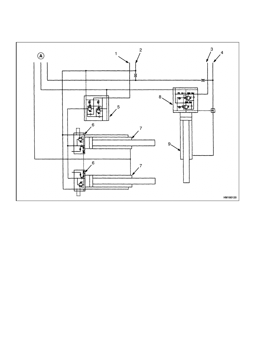
Schematics
4500 SRM 649
Schematics
A. TO TANK
1.
BOOM LIFT
2.
BOOM LOWER
3.
BOOM EXTEND
4.
BOOM RETRACT
5.
PILOT-ASSISTED, OVER-CENTER VALVE (1:13
PRESSURE RATIO)
6.
OVER-CENTER VALVE (1:20 PRESSURE RATIO)
7.
BOOM LIFT CYLINDER
8.
OVER-CENTER VALVE (1:13 PRESSURE RATIO)
9.
BOOM EXTENSION CYLINDER
Figure 20. Boom Hydraulic Schematic
34


TECHNICAL PUBLICATIONS
4500 SRM 649
3/05 (1/98) Printed in United Kingdom
Document Outline
- toc
Wyszukiwarka
Podobne podstrony:
897953 1600SRM0639 (03 2005) UK EN
1598459 1900SRM1213 (03 2005) UK EN
897956 1900SRM0642 (03 2005) UK EN
1573930 0600SRM1172 (03 2005) UK EN
1586985 2200SRM1178 (03 2005) UK EN
897345 1400SRM0413 (03 2005) UK EN
1531815 1800SRM1040 (03 2005) UK EN
899782 2000SRM0077 (03 2005) UK EN
897875 8000SRM0616 (03 2005) UK EN
897961 2200SRM0647 (03 2005) UK EN
1597925 0700SRM1211 (03 2005) UK EN
1586982 0100SRM1177 (03 2005) UK EN
1466169 4000SRM0741 (03 2005) UK EN
1495208 8000SRM0949 (03 2005) UK EN
1458783 8000SRM0592 (03 2005) UK EN
1589731 2200SRM1184 (03 2005) UK EN
1531821 1800SRM1037 (03 2005) UK EN
897825 2200SRM0596 (03 2005) UK EN
więcej podobnych podstron