TROUBLESHOOTING
AND ADJUSTMENTS
FOR MARK 3E/2
LOAD SENSING SYSTEMS
RS45-30CH, RS45-27IH, RS46-33CH, RS46-30IH,
RS46-36CH, RS46-33IH Up to 1536 [A222]
PART NO. 897956
1900 SRM 642

SAFETY PRECAUTIONS
MAINTENANCE AND REPAIR
• When lifting parts or assemblies, make sure all slings, chains, or cables are correctly
fastened, and that the load being lifted is balanced. Make sure the crane, cables, and
chains have the capacity to support the weight of the load.
• Do not lift heavy parts by hand, use a lifting mechanism.
• Wear safety glasses.
• DISCONNECT THE BATTERY CONNECTOR before doing any maintenance or repair
on electric lift trucks. Disconnect the battery ground cable on internal combustion lift
trucks.
• Always use correct blocks to prevent the unit from rolling or falling. See HOW TO PUT
THE LIFT TRUCK ON BLOCKS in the Operating Manual or the Periodic Mainte-
nance section.
• Keep the unit clean and the working area clean and orderly.
• Use the correct tools for the job.
• Keep the tools clean and in good condition.
• Always use HYSTER APPROVED parts when making repairs. Replacement parts
must meet or exceed the specifications of the original equipment manufacturer.
• Make sure all nuts, bolts, snap rings, and other fastening devices are removed before
using force to remove parts.
• Always fasten a DO NOT OPERATE tag to the controls of the unit when making repairs,
or if the unit needs repairs.
• Be sure to follow the WARNING and CAUTION notes in the instructions.
• Gasoline, Liquid Petroleum Gas (LPG), Compressed Natural Gas (CNG), and Diesel fuel
are flammable. Be sure to follow the necessary safety precautions when handling these
fuels and when working on these fuel systems.
• Batteries generate flammable gas when they are being charged. Keep fire and sparks
away from the area. Make sure the area is well ventilated.
NOTE: The following symbols and words indicate safety information in this
manual:
WARNING
Indicates a condition that can cause immediate death or injury!
CAUTION
Indicates a condition that can cause property damage!

Troubleshooting and Adjustments
Table of Contents
TABLE OF CONTENTS
General ...............................................................................................................................................................
Replacement and Adjustment ...........................................................................................................................
Load Sensing System ....................................................................................................................................
Remove.......................................................................................................................................................
Install .........................................................................................................................................................
Pressure Sensors ...........................................................................................................................................
Remove.......................................................................................................................................................
Replace .......................................................................................................................................................
Display Panel Light Bulbs ............................................................................................................................
Remove.......................................................................................................................................................
Replace .......................................................................................................................................................
Display Panel Switches .................................................................................................................................
Remove.......................................................................................................................................................
Replace .......................................................................................................................................................
Angle Potentiometer......................................................................................................................................
Verify Boom Angle .....................................................................................................................................
Adjust .........................................................................................................................................................
Replace .......................................................................................................................................................
Length Potentiometer....................................................................................................................................
Verify Boom Length...................................................................................................................................
Adjust .........................................................................................................................................................
Replace .......................................................................................................................................................
Troubleshooting..................................................................................................................................................
System Errors ................................................................................................................................................
Analog Signal Errors .....................................................................................................................................
Operating Errors ...........................................................................................................................................
This section is for the following models:
RS45-30CH, RS45-27IH, RS46-33CH, RS46-30IH, RS46-36CH,
RS46-33IH Up to 1536 [A222]
©2005 HYSTER COMPANY
i

"THE
QUALITY
KEEPERS"
HYSTER
APPROVED
PARTS
1900 SRM 642
General
General
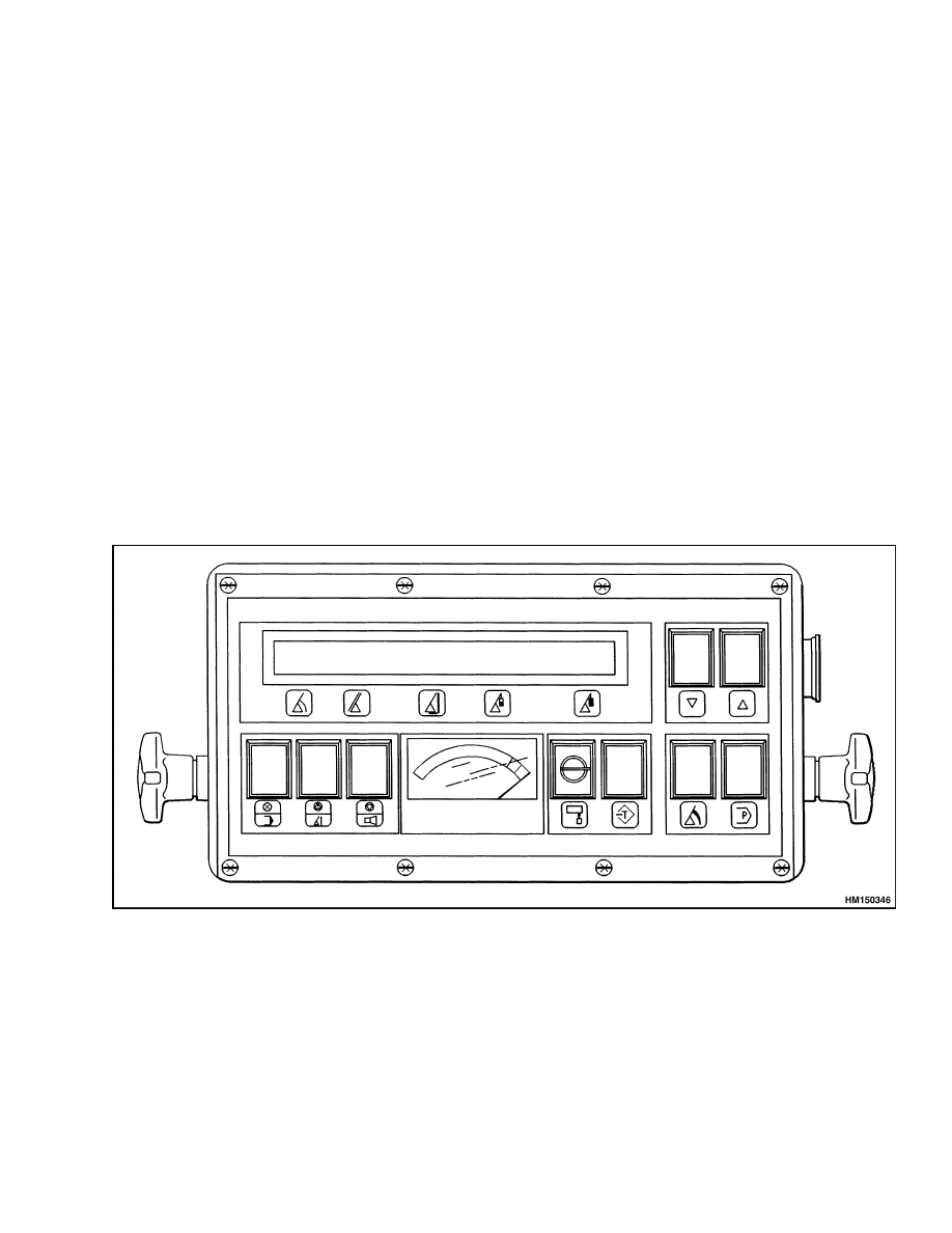
The Load Sensing System is a KRUGER Mark 3E/2
System. It is an electronic/mechanical load sensing
system designed to indicate the allowable lifting
capacity of the reach stacker. The display panel is
shown in Figure 1.
The system consists of the following components:
• Display Panel mounted in the cab
• Junction Box with Shut Off Relay
• Spring-Operated Cable Reel with Angle and
Length Sensor
• Hydraulic Load Sensors
• Area Definition Sensors
Each Load Sensing System is factory programmed
to match the specific truck to which it is mounted.
By programming the unit with the information re-
quested during the start up sequence, the system
monitors and displays:
• Program Information
• Load Sensing
• Boom Angle
• Boom Length
• Boom Radius
• Actual Load on the attachment
• Maximum Load Allowed
• Service Information
The system continually monitors output from the
force and configuration sensors. It integrates the
programmed inputs from the display panel switches,
force sensors, and configuration sensors and com-
pares this information to the manufacturer’s capac-
ity charts, which are stored in the central processor
of the Load Sensing System.
The resulting data is displayed for the operator. If
an overload condition is determined, the operator is
warned with an audible and visual alarm and the hy-
draulic functions used to create the overload condi-
tion are disabled. The hydraulic functions necessary
to correct the overload condition are still enabled.
Figure 1. Load Sensing System Display Panel
1
Replacement and Adjustment
1900 SRM 642
Replacement and Adjustment
CAUTION
These instructions must be followed com-
pletely or the system may have to be calibrated
by a Hyster Company technician.
This section provides step-by-step procedures to re-
place the components of the system and to perform
the necessary adjustments on these components.
Please read through the replacement and adjust-
ment procedures before you attempt to replace a
component or make an adjustment.
If a compo-
nent replacement is necessary, order the component
from your Hyster Company authorized dealer be-
fore removing the component. Include truck model
and serial number when ordering to ensure proper
operation over the range of the original system in-
stallation.
LOAD SENSING SYSTEM
The Load Sensing System display panel is mounted
on a bracket in the operator’s cab next to the opera-
tor’s instrument panel. It consists of a display panel
and indicator switches used to monitor the load.
Remove
1.
Remove the 26-pin connector from the bottom of
the Load Sensing System.
2.
Remove the two black plastic knobs from the
sides of the system. Retain the knobs for future
use.
3.
Remove the system from the mounting bracket.
Install
1.
Install the Load Sensing System in the mounting
bracket.
2.
Install the two black plastic knobs in the sides of
the system and tighten.
3.
Install the 26-pin connector in the bottom of the
system.
PRESSURE SENSORS
The pressure sensors are mounted on the lift cylin-
ders.
Remove
1.
Place a drip pan underneath the pressure sen-
sors to catch any fluid spilled when the pressure
sensors are removed.
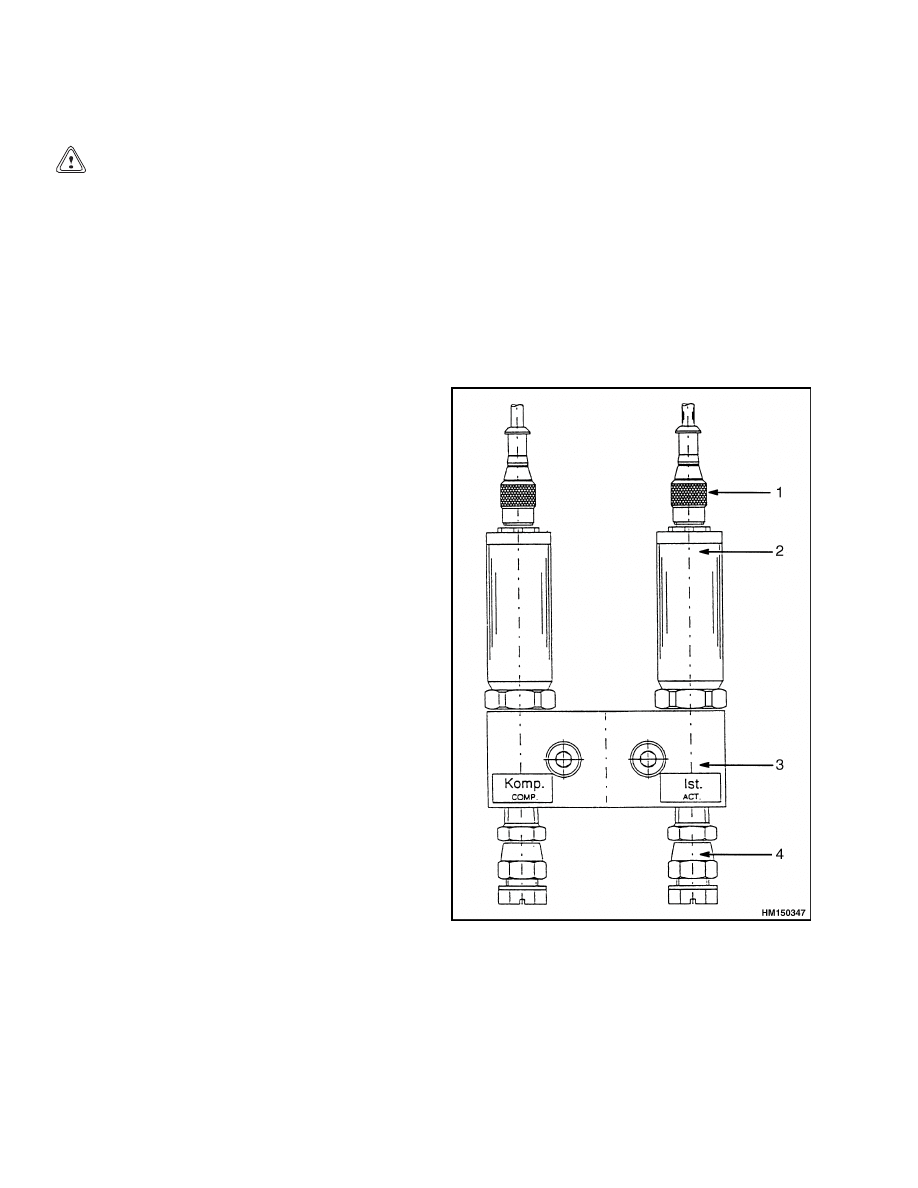
2.
Remove the hydraulic connectors from the pres-
sure sensor. See Figure 2.
3.
Remove the pressure sensors from the hydraulic
block.
4.
Place end caps on the disconnected hydraulic
lines.
1.
HYDRAULIC CONNECTOR
2.
PRESSURE SENSOR
3.
HYDRAULIC BLOCK
4.
HYDRAULIC ADAPTER
Figure 2. Pressure Sensors
2

1900 SRM 642
Replacement and Adjustment
Replace
1.
Place a drip pan underneath the pressure sen-
sors to catch any fluid spilled when the pressure
sensors are installed.
2.
Install the pressure sensors onto the hydraulic
block. See Figure 2.
3.
Remove the end caps from the hydraulic lines.
4.
Connect the hydraulic lines to the pressure sen-
sors.
DISPLAY PANEL LIGHT BULBS
Remove
1.
Use a small, flat-blade screwdriver to pry the
lens cover from the switch actuator on the dis-
play panel.
2.
Use needle-nose pliers to carefully remove the
lamp from the lamp socket.
Replace
1.
Use needle-nose pliers to carefully insert the
lamp into the lamp socket.
2.
Install the lens cover onto the switch actuator.
Make sure the lens cover snaps into place.
DISPLAY PANEL SWITCHES
Remove
1.
Remove the eight screws from the front of the
display panel.
2.
Carefully remove the panel from the housing.
3.
Disconnect the ribbon cable at the PC board con-
nector.
4.
Disconnect the two-wire connector from the
26-pin plug on the bottom of the housing.
5.
At the back of the display panel behind the
switch actuator, rotate the retaining ring coun-
terclockwise to loosen the switch actuator.
6.
Remove the switch actuator from the front of the
display panel.
Replace
1.
Position the switch actuator retaining ring be-
hind the hole in the switch panel.
2.
Insert the new switch actuator into the display
panel from the front and into the retaining ring.
3.
Push the switch actuator into the switch socket
until the switch actuator is firmly seated in the
socket.
4.
Hold the switch actuator at the front of the panel
to prevent it from moving and tighten the retain-
ing ring.
ANGLE POTENTIOMETER
Verify Boom Angle
Use this procedure to verify that the actual boom an-
gle agrees with the angle shown on the Load Sensing
System display.
1.
Lower the boom to 0 angle. Use an angle pro-
tractor to verify angle of boom.
2.
Compare the actual angle to the angle displayed
on the display panel.
3.
Raise the boom to a high angle. Use an angle
protractor to verify the actual angle.
4.
Compare the actual angle to the angle displayed
on the panel.
5.
If the actual boom angle and the displayed boom
angle do not agree, perform the angle poten-
tiometer adjustment procedure.
Adjust
1.
Fully retract the boom and lower to an angle that
provides access to the cable reel mounted on the
boom base section.
2.
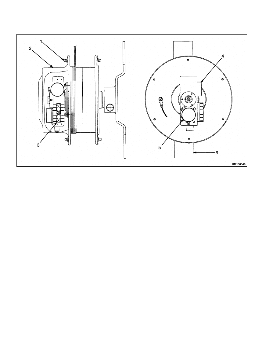
Remove the six capscrews holding the cable reel
cover in place. See Figure 3. Store the screws,
washers, and clamps in a safe place.
3.
Remove cable reel cover.
4.
Supply power to the Load Sensing System.
3
Replacement and Adjustment
1900 SRM 642
1.
CAPSCREWS
2.
COVER
3.
TERMINAL STRIP
4.
LENGTH POTENTIOMETER
5.
ANGLE POTENTIOMETER
6.
PENDULUM
Figure 3. Cable Reel Components
5.
Follow the system start up procedure to put the
display panel in the normal operating mode.
6.
Move the boom up to 5 or 6 degrees. Verify using
the magnetic base angle protractor.
7.
If the angle displayed on the panel agrees with
the actual angle shown on the angle protractor
proceed to Step 9.
8.
If the angle displayed on the panel does not agree
with the actual angle shown on the angle protrac-
tor proceed as follows:
a. Loosen, but do not remove the three screws
holding the angle potentiometer clamps.
b. Slowly rotate the potentiometer until the an-
gle indication on the panel is the same as the
actual angle on the angle protractor.
c.
Tighten the three screws that hold the angle
potentiometer clamps.
9.
Move the boom up to the maximum angle possi-
ble. Verify the actual boom angle using the mag-
netic base angle protractor.
10. If the angle displayed on the panel agrees with
the actual angle shown on the angle protractor
go to Step 12.
11. If the angle displayed on the panel does not agree
with the actual angle shown on the angle protrac-
tor proceed as follows:
a. Loosen, but do not remove the three screws
holding the angle potentiometer clamps.
b. Slowly rotate the potentiometer until the an-
gle indication on the panel is the same as the
actual angle on the angle protractor.
c.
Tighten the three screws that hold the angle
potentiometer clamps.
4

1900 SRM 642
Replacement and Adjustment
NOTE: Step 6 to Step 11 may need to be repeated
more than once.
12. Lower the boom and install the cable reel cover.
Replace
If the actual boom angle and the boom angle dis-
played on the Load Sensing System cannot be made
to agree by adjustment, replace the angle poten-
tiometer using this procedure.
1.
Fully retract the boom and lower it to an angle
that provides access to the cable reel mounted on
the boom base section.
2.
Turn off power to the Load Sensing System.
3.
Remove the six capscrews holding the cable reel
cover in place. See Figure 3. Store the screws,
washers, and clamps in a safe place.
4.
Remove the cable reel cover.
5.
Remove the three wires from the angle poten-
tiometer at the terminal strip. These should be
number #4, #5, and #6 on the terminal strip.
6.
Remove the screws and nuts holding the angle
potentiometer bracket to the cable reel.
7.
Install the new angle potentiometer in reverse
sequence.
8.
Connect the wires from the angle potentiometer
to the terminal strip:
BLUE to #4
BLACK to #5
GREEN to #6
9.
Supply power to the Load Sensing System.
10. Follow the system startup procedure to put the
display panel in the normal operating mode.
11. See Angle Potentiometer, Adjust for the adjust-
ment procedure.
LENGTH POTENTIOMETER
Verify Boom Length
1.
Select a program configuration that measures
only main boom length. Fully retract the main
boom.
2.
The display panel should indicate a main boom
length comparable to the shortest main boom
length on the capacity chart.
3.
Fully extend the main boom. The display panel
should indicate a boom length comparable to the
longest main boom length on the capacity chart.
A variation of approximately ±1 mm (±3 ft) would
indicate one wrap of cable was removed or added to
the cable reel.
Adjust
1.
Locate machine in an area that will allow you
to safely extend the boom to its full extension
(powered sections plus manual section).
2.
Fully retract the boom and lower it to an angle
that provides access to the cable reel mounted on
the boom base section.
3.
Remove the six capscrews holding the cable reel
cover in place. See Figure 3. Store the screws,
washers, and clamps in a safe place.
4.
Remove the cable reel cover.
5.
Follow the system startup procedure to put the
display panel in the normal operating mode.
6.
With all boom sections fully retracted, loosen
setscrews and rotate the lever arm on the length
potentiometer until the length displayed on the
panel indicates the shortest boom length shown
on the truck capacity chart.
7.
Fully extend all boom sections, including the
manual section. The display panel should dis-
play the maximum extended boom length.
8.
Fully retract all boom sections. including the
manual section. The display panel should dis-
play the fully retracted length originally set in
Step 6.
a. If the length on the panel agrees with the
length set in Step 6, go to Step 9.
b. If the length displayed does not agree with
the length set in Step 6, the lever arm has
slipped. Tighten the setscrews and repeat
Step 6 through Step 8.
9.
Install the cable reel cover.
5

Replacement and Adjustment
1900 SRM 642
Replace
1.
Locate machine in an area that will allow you to
safely extend the boom to its full extension.
2.
Fully retract the boom and lower it to an angle
that provides access to the cable reel mounted on
the boom base section.
3.
Turn off power to the Load Sensing System.
4.
Remove the six capscrews holding the cable reel
cover in place. See Figure 3. Store the screws,
washers, and clamps in a safe place.
5.
Remove the cable reel cover.
6.
Remove the length potentiometer from the
mounting bracket.
7.
Rotate the LEVER arm attached to the length
potentiometer until the setscrew is accessible.
Loosen, but do not remove the setscrew.
8.
Rotate the arm until the second setscrew is ac-
cessible. Loosen, but do not remove the setscrew.
9.
Remove the arm from the length potentiometer.
10. Remove the nylon gear from the length poten-
tiometer shaft.
11. Remove the length potentiometer from the
mounting bracket.
12. Remove the three wires from the length poten-
tiometer at the terminal strip. These are #1, #2,
and #3 on the terminal strip.
13. Install the new length potentiometer in the
mounting bracket. Tighten only finger tight at
this time.
14. Make sure there is a gap between the poten-
tiometer and mounting bracket to ensure the
proper mesh of the gear set. Tighten the nut
on the potentiometer tightly to secure it in the
bracket.
15. Install the large nylon gear on the potentiometer
shaft. Make sure that the brass spacer is facing
toward the boom.
16. Install the lever arm on the potentiometer shaft
and tighten both setscrews.
17. Connect the wires from the Length Potentiome-
ter to the terminal strip:
BLUE to #1
BLACK to #2
GREEN to #3
18. Set a volt-ohmmeter to read ohms. Place one
probe on terminal #1 of the terminal strip and
the other probe on terminal #2.
19. Turn the lever arm until the meter indicates ap-
proximately 95 ohms. Remove the meter from
the terminal strip.
20. Apply power to the Load Sensing System.
21. Follow the system startup procedure to put the
display panel in the normal operating mode.
22. With all boom sections fully retracted, rotate
the lever arm on the length potentiometer until
the length displayed on the panel indicates the
shortest boom length shown on the truck capac-
ity chart.
23. Fully extend all boom sections, including the
manual section. The panel should display the
maximum extended boom length.
24. Fully retract all boom sections including the
manual section. The panel should display the
fully retracted length originally set in Step 22.
a. If the length on the panel agrees with the
length set in Step 22, go to Step 25.
b. If the length displayed does not agree with
the length set in Step 22, the lever arm has
slipped. Tighten the setscrews and repeat
Step 22 through Step 24.
25. Reinstall the cable reel cover.
6

1900 SRM 642
Troubleshooting
Troubleshooting
This publication is designed to assist the techni-
cian in the troubleshooting and basic repair on the
KRUGER Mark 3E/2 Load Sensing System.
The Mark 3E/2 System operates on various voltages.
The specific voltage is determined by the circuit. Ex-
cessive variation of the voltage inputs to the circuitry
can cause the system to provide erratic output infor-
mation. The Mark 3E/2 System continuously moni-
tors each circuit and produces an error message when
normal circuit parameters are exceeded.
Operating Errors can occur by selecting improper
boom configurations or exceeding the allowable pa-
rameters of the truck functions. Operating errors
are displayed in plain language.
For assistance in identifying the source of a problem
where only an ERROR CODE NO. appears on the
panel display, refer to the error code description for
additional information. Error Codes 01 through 08
and 70 through 81 indicate that the repair can only
be performed by a Hyster Company authorized tech-
nician.
Three types of messages are generated by the Load
Sensing System: system errors, analog signal errors,
and operating errors. If errors are detected, they
are shown on the alphanumeric, dot-matrix display
panel.
SYSTEM ERRORS
System Errors are normally caused by defective
hardware or malfunctioning programmed data
stores. When a System error occurs, the green light
on the control panel goes out.
System errors are
displayed with a two-digit code number.
Error codes are displayed as code numbers only.
They are related to problems that are internal to the
system and require evaluation and repair by a fac-
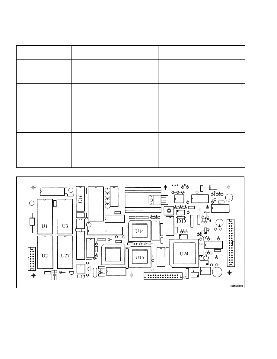
tory authorized technician. See Table 1. Component
layout of the display panel is shown in Figure 4.
Table 1. System Errors
Fault (Error
Message)
Probable Cause
Solution
Code No. 01
(Watchdog Error)
Program not functioning properly.
Press and release green button on
control panel. If fault is not corrected,
contact your Hyster Company
authorized dealer.
Code No. 02
(Checksum for
operating system
EEPROM is not correct)
Checksum calculated by the system is
different than the checksum stored in
the operating system EPROM (U1).
Defective EPROM (U1).
Electrical failure of board.
Press and release green button on
control panel. If fault is not corrected,
contact your Hyster Company
authorized dealer.
Code No. 03
(Checksum Data
EPROM #1 is not
correct)
Checksum calculated by the system
differs from the checksum stored in
data EPROM (U3).
Defective EPROM (U3).
Defective EPROM (U1).
Electrical failure of board.
Press and release green button on
control panel. If fault is not corrected,
contact your Hyster Company
authorized dealer.
Code No. 04
(Checksum EEPROM
#2 is not correct)
Checksum calculated by the system
differs from the checksum stored in
data EEPROM (U2).
Defective EPROM (U3).
Electrical failure of board.
Press and release green button on
control panel. If fault is not corrected,
contact your Hyster Company
authorized dealer.
7
Troubleshooting
1900 SRM 642
Table 1. System Errors (Continued)
Fault (Error
Message)
Probable Cause
Solution
Code No. 05
(RAM Error Port 1)
Defective IC (U14).
Press and release green button on
control panel. If fault is not corrected,
contact your Hyster Company
authorized dealer.
Code No. 06
(RAM Error Port 2)
Defective IC (U15).
Press and release green button on
control panel. If fault is not corrected,
contact your Hyster Company
authorized dealer.
Code No. 07
(RAM Error Static RAM
6116)
Defective static RAM 6116 (U27).
Press and release green button on
control panel. If fault is not corrected,
contact your Hyster Company
authorized dealer.
Code No. 08
(RAM Error Serial
EEPROM)
Defective serial EEPROM (U13).
Press and release green button on
control panel. If fault is not corrected,
contact your Hyster Company
authorized dealer. This may require
complete system calibration to repair
fault.
Figure 4. Display Panel, Component Layout
8

1900 SRM 642
Troubleshooting
ANALOG SIGNAL ERRORS
The analog error codes are displayed in plain lan-
guage, as well as with an error code number. See
Table 2. Cause for these error codes could be open or
shorted wiring to external analog components or de-
fective external components. All threshold voltages
are based on the analog to digital converter input lev-
els.
Try to eliminate the error message by pushing the
green button. If this does not correct the problem, try
to identify and correct the problem using the solution
in Table 2.
The pressure settings of the boom hoist cylinder hold-
ing valves affect load indication. If either holding
valve is replaced, it may be necessary to calibrate the
system.
Table 2. Analog Signal Errors
Fault (Error
Message)
Probable Cause
Solution
Check all wiring from the individual
pressure sensors to the junction box.
Check the pressure sensors for physical
damage and replace if needed.
Check junction box terminals 2, 3, or 4
for 0 VDC (system ground).
Check junction box terminals 5, 6, or 7
for +12 VDC (supply voltage).
Check terminal 30 for a voltage
between +2.5 and +7.5 VDC (output of
pressure sensor).
Defect in the cable between the junction
box and the pressure sensor (high
output voltage).
Defective pressure sensor.
Check the voltage between terminals
2, 3, or 4 and terminal 30. Voltage
above +8.20 indicates a damaged cable
between the junction box and the
pressure sensor or a damaged sensor.
Sensor Output E:10
(Press/Piston)
Defect in the cable between the junction
box and the display panel.
Defective display panel.
Check the voltage between terminals
2, 3, or 4 and terminal 30. A voltage
between +2.5 and +7.5 VDC indicates
a damaged cable between the junction
box and the display panel or a defective
display panel.
9

Troubleshooting
1900 SRM 642
Table 2. Analog Signal Errors (Continued)
Fault (Error
Message)
Probable Cause
Solution
Check all wiring from the individual
pressure sensors to the junction box.
Check the pressure sensors for physical
damage and replace if needed.
Check junction box terminals 2, 3, or 4
for 0 VDC (system ground).
Check junction box terminals 5, 6, or 7
for +12 VDC (supply voltage).
Check terminal 30 for voltage of +2.5 to
+7.5 VDC (output of pressure sensor).
Defect in the cable between the junction
box and the pressure sensor (low output
voltage).
Defective pressure sensor.
Check the voltage between terminals
2, 3, or 4 and terminal 30. Voltage less
than +1.85 VDC indicates a damaged
cable between the junction box and the
pressure sensor or a damaged sensor.
Sensor Output E:11
(Press/Piston)
Defect in the cable between the junction
box and the display panel.
Defective display panel.
Check the voltage between terminals
2, 3, or 4 and terminal 30. A voltage
between +2.5 and +7.5 VDC indicates
a damaged cable between the junction
box and the display panel or a defective
display panel.
10

1900 SRM 642
Troubleshooting
Table 2. Analog Signal Errors (Continued)
Fault (Error
Message)
Probable Cause
Solution
Check all the wiring between the
junction box and the cable reel for
physical damage.
Check for loose connections at
receptacles and other connection
points.
With the boom fully retracted, check
junction box terminals 37 or 38 for 0
VDC (length potentiometer ground).
With the boom fully retracted, check
junction box terminals 39 or 40 for +5.0
VDC (length potentiometer supply).
Defect in the cable between the junction
box and the length potentiometer (high
output voltage).
Defective length potentiometer.
With the boom fully retracted, check
junction box terminal 31 for +1.0 VDC
(length potentiometer output).
Defect in the cable between the junction
box and the display panel.
Defective display panel.
Check the voltage between terminals
37 or 38 and terminal 31. Voltage less
than +4.8 VDC indicates a damaged
cable between the junction box and the
display panel or a defective display
panel.
Inspect the length potentiometer for
physical damage. Replace if necessary.
Check the voltage between pins 1 and
3 on the terminal strip in the cable reel
for +5.0 VDC. If the voltage is not +5.0
VDC, the problem is in the wiring to
the junction box.
Sensor Output E:20
(Length)
Defect in the cable between the junction
box and the length potentiometer.
Defective length potentiometer.
Check the voltage between pins 1 and
2. If the voltage is greater than +4.8
VDC, replace the length potentiometer.
11

Troubleshooting
1900 SRM 642
Table 2. Analog Signal Errors (Continued)
Fault (Error
Message)
Probable Cause
Solution
Check all the wiring between the
junction box and the cable reel for
physical damage.
Check for loose connections at
receptacles and other connection
points.
With the boom fully retracted, check
junction box terminals 37 or 38 for 0
VDC (length potentiometer ground).
With the boom fully retracted, check
junction box terminals 39 or 40 for +5.0
VDC (length potentiometer supply).
Defect in the cable between the junction
box and the length potentiometer (low
output voltage).
Defective length potentiometer.
With the boom fully retracted, check
junction box terminal 31 for +1.0 VDC
(length potentiometer output).
Defect in the cable between the junction
box and the display panel.
Defective display panel.
Check the voltage between terminals
37 or 38 and terminal 31. Voltage less
than +0.7 VDC indicates a damaged
cable between the junction box and the
display panel or a defective display
panel.
Inspect the length potentiometer for
physical damage. Replace if necessary.
Check the voltage between pins 1 and
3 on the terminal strip in the cable reel
for +5.0 VDC. If the voltage is not +5.0
VDC, the problem is in the wiring to
the junction box.
Sensor Output E:21
(Length)
Defect in the cable between the junction
box and the length potentiometer.
Defective length potentiometer.
Check the voltage between pins 1 and
2. If the voltage is greater than +0.7
VDC, replace the length potentiometer.
12

1900 SRM 642
Troubleshooting
Table 2. Analog Signal Errors (Continued)
Fault (Error
Message)
Probable Cause
Solution
Check all the wiring between the
junction box and the cable reel for
physical damage.
Check for loose connections at
receptacles and other connection
points.
With the boom fully retracted and the
boom at 0 degrees, check junction box
terminals 37 or 38 for 0 VDC (angle
potentiometer ground).
With the boom fully retracted and the
boom at 0 degrees, check junction box
terminals 39 or 40 for +5.0 VDC (angle
potentiometer supply).
Defect in the cable between the junction
box and the angle potentiometer (high
output voltage).
Defective angle Potentiometer.
With the boom fully retracted and
the boom at 0 degrees, check junction
box terminal 32 for +1.0 VDC (angle
potentiometer output).
Defect in the cable between the junction
box and the display panel.
Defective display panel.
Check the voltage between terminals
37 or 38 and terminal 32. Voltage less
than +4.1 VDC indicates a damaged
cable between the junction box and the
display panel or a defective display
panel.
Inspect the angle potentiometer for
physical damage. Replace if necessary.
Check the voltage between pins 4 and
6 on the terminal strip in the cable reel
for +5.0 VDC. If the voltage is not +5.0
VDC, the problem is in the wiring to
the junction box.
Sensor Output E:30
(Angle)
Defect in the cable between the junction
box and the angle potentiometer.
Defective angle potentiometer.
Check the voltage between pins 4 and
5. If the voltage is greater than +4.1
VDC, replace the angle potentiometer.
13

Troubleshooting
1900 SRM 642
Table 2. Analog Signal Errors (Continued)
Fault (Error
Message)
Probable Cause
Solution
Check all the wiring between the
junction box and the cable reel for
physical damage.
Check for loose connections at
receptacles and other connection
points.
With the boom fully retracted and the
boom at 0 degrees, check junction box
terminals 37 or 38 for 0 VDC (angle
potentiometer ground).
With the boom fully retracted and the
boom at 0 degrees, check junction box
terminals 39 or 40 for +5.0 VDC (angle
potentiometer supply).
Defect in the cable between the junction
box and the angle potentiometer (low
output voltage).
Defective angle potentiometer.
With the boom fully retracted and
the boom at 0 degrees, check junction
box terminal 32 for +1.0 VDC (angle
potentiometer output).
Defect in the cable between the junction
box and the display panel.
Defective display panel.
Check the voltage between terminals
37 or 38 and terminal 32. Voltage less
than +0.6 VDC indicates a damaged
cable between the junction box and the
display panel or a defective display
panel.
Inspect the angle potentiometer for
physical damage. Replace if necessary.
Check the voltage between pins 4 and
6 on the terminal strip in the cable reel
for +5.0 VDC. If the voltage is not +5.0
VDC, the problem is in the wiring to
the junction box.
Sensor Output E:31
(Angle)
Defect in the cable between the junction
box and the angle potentiometer.
Defective angle potentiometer.
Check the voltage between pins 4 and
5. If the voltage is greater than +4.1
VDC, replace the angle potentiometer.
14

1900 SRM 642
Troubleshooting
Table 2. Analog Signal Errors (Continued)
Fault (Error
Message)
Probable Cause
Solution
Check all the wiring between the
junction box and the pressure sensors
for physical damage.
Check for loose connections at
receptacles and other connection
points.
Inspect the pressure sensor for physical
damage. Replace if necessary.
With no load on the boom, check
junction box terminals 2, 3, or 4 for 0
VDC (system ground).
With no load on the boom, check
junction box terminals 5, 6, or 7 for
+12.0 VDC (supply voltage).
With no load on the boom, check
junction box terminal 35 for a voltage
between +2.5 and +7.5 VDC (pressure
sensor output).
Defect in the cable between the junction
box and the pressure sensors (high
output voltage). Defective pressure
sensor.
Check the voltage between terminals
2, 3, or 4 and terminal 35. Voltage
above +8.20 VDC indicates a damaged
cable between the junction box and the
pressure sensor or a defective pressure
sensor.
Sensor Output E:60
(Rod)
Defect in the cable between the junction
box and the display panel.
Defective display panel.
Check the voltage between terminals
2, 3, or 4 and terminal 35. A voltage
between +2.5 and +7.5 VDC indicates
a damaged cable between the junction
box and the display panel or a defective
display panel.
15

Troubleshooting
1900 SRM 642
Table 2. Analog Signal Errors (Continued)
Fault (Error
Message)
Probable Cause
Solution
Check all the wiring between the
junction box and the pressure sensors
for physical damage.
Check for loose connections at
receptacles and other connection
points.
Inspect the pressure sensor for physical
damage. Replace if necessary.
With no load on the boom, check
junction box terminals 2, 3, or 4 for 0
VDC (system ground).
With no load on the boom, check
junction box terminals 5, 6, or 7 for
+12.0 VDC (supply voltage).
With no load on the boom, check
junction box terminal 35 for a voltage
between +2.5 and +7.5 VDC (pressure
sensor output).
Defect in the cable between the junction
box and the pressure sensors (low
output voltage).
Defective pressure sensor.
Check the voltage between terminals
2, 3, or 4 and terminal 35. Voltage less
than +1.85 VDC indicates a damaged
cable between the junction box and the
pressure sensor or a defective pressure
sensor.
Sensor Output E:61
(Rod)
Defect in the cable between the junction
box and the display panel.
Defective display panel.
Check the voltage between terminals
2, 3, or 4 and terminal 35. A voltage
between +2.5 and +7.5 VDC indicates
a damaged cable between the junction
box and the display panel or a defective
display panel.
Code No. 70
Actual checksum of the operating
system EPROM (U1) is different than
the checksum stored in the serial
EEPROM (U13).
Data may be corrupted.
Contact your Hyster Company
authorized dealer.
16

1900 SRM 642
Troubleshooting
Table 2. Analog Signal Errors (Continued)
Fault (Error
Message)
Probable Cause
Solution
Code No. 71
Actual checksum of the data EPROM
#1 (U3) is different than the checksum
stored in the serial EEPROM (U13).
Data may be corrupted.
Contact your Hyster Company
authorized dealer.
Code No. 72
Actual checksum of the data EPROM
#2 (U2) is different than the checksum
stored in the serial EEPROM (U13).
Data may be corrupted.
Contact your Hyster Company
authorized dealer.
Code No. 74
An incorrect EEPROM is installed in
location (U2) of the CPU board.
Contact your Hyster Company
authorized dealer.
Code No. 75
An incorrect EEPROM is installed in
location (U3) of the CPU board.
Contact your Hyster Company
authorized dealer.
Code No. 80
Defective IC (U15). Time clock does not
run.
Contact your Hyster Company
authorized dealer.
Code No. 81
Defective A-to-D converter (U24).
Contact your Hyster Company
authorized dealer.
Create A-2-B shutoff condition and
check junction box terminal 17 for +5
VDC.
If voltage is present, check external
wiring for damage.
If voltage is not present, check relay
K2.
Code No. 82
Failure of A-2-B shutoff circuit.
Defective wiring in A-2-B shutoff circuit
or in LM shutoff circuit.
Defective junction box relay K2 or K4.
Defective display panel.
Defect in the cable between the junction
box and the display panel.
Create an LM shutoff condition and
check junction box terminal 18 for +12
VDC.
If voltage is not present, check external
wiring for damage.
If +12 VDC is present, check terminal
23 for +5 VDC.
If +5 VDC is present, check the display
panel.
If +5 VDC is not present, check relays
K2 and K4. If the relays are good,
check the cable between the junction
box and the display panel.
17

Troubleshooting
1900 SRM 642
Table 2. Analog Signal Errors (Continued)
Fault (Error
Message)
Probable Cause
Solution
Code No. 83
Power supply voltage to system drops
below 10.3 VDC.
Defective truck charging system.
Defective fuse.
Defective power converter.
Check junction box terminal 1 for +24
VDC.
If voltage is less than +10.3 VDC, check
the truck electrical charging system.
If there is no voltage, check the fuse.
If the voltage is greater than +10.3
VDC, check the voltage on terminals
5, 6, and 7.
If the voltage on terminals 5, 6, and
7 is less than +10.3 VDC, replace the
power converter.
Code No. 84
Regulated +5 VDC power source is out
of range (+4.875 to +5.125 VDC).
Defective D-A converter.
Defective wiring from the junction box
to the display panel.
Defective display panel.
Check the voltage between junction box
terminals 37 or 38 and 39 or 40.
If the voltage is below +4.875 VDC,
remove all electrical connections from
terminals 39 and 40 except the red and
blue wires.
Check the voltage again.
If the voltage is within the acceptable
range, the wiring from the junction
panel is defective or the display panel
is defective.
If the voltage is still out of range,
contact your Hyster Company
authorized dealer.
Code No. 90
Does not apply.
OPERATING ERRORS
Operating errors are displayed on the control panel.
These errors are normally caused by operation out-
side of the programmed machine capacity chart
values or when actual machine configuration differs
from the programmed configuration.
To monitor the actual conditions that have caused the
error message to be displayed, push and release one
of the blue push buttons. This will change the display
from the error message to the actual truck configura-
tion information including boom angle, boom length,
radius, load on the hook, and maximum load. This
can be compared to the truck manufacturer’s capac-
ity chart to assist the operator in selecting the safest
method to correct the problem. See Table 3.
When the condition which caused the error message
to be displayed is corrected, the system automatically
resets to the normal operating mode.
18

1900 SRM 642
Troubleshooting
Table 3. Operating Errors
Fault (Error
Message)
Probable Cause
Solution
Maximum Capacity
1.
Load exceeds rated capacity.
2.
Boom
extended
beyond
rated
length.
1.
Reduce load.
2.
Shorten radius of boom.
Nonworking Area
1.
Attempting to operate in a nonap-
proved area.
1.
Move boom or truck to approved po-
sition. Check load chart.
No Load Calculation
Possible
1.
Boom
length
exceeds
the
pro-
grammed length of the pressure
profile.
1.
Retract the boom. Make sure that
programmed length is within oper-
ating parameters.
Boom Length Shorter
Than Load Chart
1.
Actual boom length is shorter than
the programmed configuration.
1.
Compare the actual displayed boom
length to the capacity chart.
2.
Make sure that the LMI configura-
tion setting matches the actual ma-
chine configuration.
3.
Verify that boom length is correct.
Boom Length Longer
Than Load Chart
1.
Actual boom length is longer than
the programmed configuration.
1.
Compare the actual displayed boom
length to the capacity chart.
2.
Make sure that the LMI configura-
tion setting matches the actual ma-
chine configuration.
3.
Verify that boom length is correct.
Boom Angle Below Load
Chart
1.
Boom is lowered to a position less
than angle or load capacity chart.
1.
Compare displayed boom angle to
capacity chart.
2.
Raise or increase boom angle.
3.
Verify that boom angle is correct.
Boom Angle Above Load
Chart
1.
Boom is raised to a position that
exceeds the angle or load capacity
chart.
1.
Compare displayed boom angle to
capacity chart.
2.
Lower or decrease boom angle.
3.
Verify that boom angle is correct.
Radius Shorter than
Load Chart
NOTE: The radius is cal-
culated from input infor-
mation of Boom Length
and Boom Angle.
1.
Boom radius is reduced to a value
less than the capacity chart.
1.
Compare displayed boom radius to
capacity chart.
2.
Lower boom angle or increase boom
length.
Radius Longer Than
Load Chart
1.
Boom radius is increased to a value
greater than the capacity chart.
1.
Compare displayed boom radius to
capacity chart.
2.
Raise boom angle or decrease boom
length.
19

NOTES
____________________________________________________________
____________________________________________________________
____________________________________________________________
____________________________________________________________
____________________________________________________________
____________________________________________________________
____________________________________________________________
____________________________________________________________
____________________________________________________________
____________________________________________________________
____________________________________________________________
____________________________________________________________
____________________________________________________________
____________________________________________________________
____________________________________________________________
____________________________________________________________
____________________________________________________________
____________________________________________________________
____________________________________________________________
____________________________________________________________
20


TECHNICAL PUBLICATIONS
1900 SRM 642
3/05 (11/97) Printed in United Kingdom
Document Outline
- toc
- tables
Wyszukiwarka
Podobne podstrony:
1598459 1900SRM1213 (03 2005) UK EN
897953 1600SRM0639 (03 2005) UK EN
910091 1900SRM0097 (08 2005) UK EN
897963 4500SRM0649 (03 2005) UK EN
1573930 0600SRM1172 (03 2005) UK EN
1586985 2200SRM1178 (03 2005) UK EN
897345 1400SRM0413 (03 2005) UK EN
1531815 1800SRM1040 (03 2005) UK EN
1466217 1900SRM0743 (06 2005) UK EN
899782 2000SRM0077 (03 2005) UK EN
897875 8000SRM0616 (03 2005) UK EN
897961 2200SRM0647 (03 2005) UK EN
1597925 0700SRM1211 (03 2005) UK EN
1586982 0100SRM1177 (03 2005) UK EN
1466169 4000SRM0741 (03 2005) UK EN
1495208 8000SRM0949 (03 2005) UK EN
więcej podobnych podstron