P E O P L E
P R O D U C T S
V I S I O N
A Minebea Group Company
Precision
Step Motors
P E O P L E
P R O D U C T S
V I S I O N
ISO 9002
QS 9000
ISO 9001
SMC 11/98
d in USA
P E O P L E
P R O D U C T S
V I S I O N
International Sales Offices
NMB Corporation Sales Offices
North America
Corporate Headquarters
9730 Independence Avenue, Chatsworth, CA 91311
Ph. 818-341-0820, Fax 818-709-0387
Western Regional Office
1735 Technology Drive, Suite 700, San Jose, CA 95110
Ph. 408-437-5636, Fax 408-437-5610
Western District Office
9730 Independence Avenue, Chatsworth, CA 91311
Ph. 818-341-0820, Fax 818-341-7316
Central Regional Office
50 East Commerce Drive, Suite A, Schaumburg, IL 60173
Ph. 847-843-3233, Fax 847-843-0955
Eastern Regional Office
4025 Steve Reynolds Boulevard, Suite 106, Norcross, GA 30093
Ph. 770-923-4477, Fax 770-923-8811
NMB Automotive
28700 Beck Road, Wixom, MI 48393
Ph. 248-926-0026, Fax 248-926-0025
S ˜ao Paulo, Brazil
Shanghai, China
Berkshire, England
Baillet en France, France
Langen, Germany
Kowloon, Hong Kong
Milan, Italy
Tokyo, Japan
Penang, Malaysia
Amsterdam, The Netherlands
Manila, Philippines
Singapore
Seoul, South Korea
Taipei, Taiwan
Bangkok, Thailand
Represented by:
A Minebea Group Company
9730 Independence Avenue
Chatsworth, CA 91311 U.S.A.
Tel: 818.341.0820
Fax: 818.709.0387
E-mail: info@nmbcorp.com
Web site: www.nmbcorp.com
ISO 14001

P E O P L E
P R O D U C T S
V I S I O N
A Minebea Group Company
9730 Independence Avenue
Chatsworth, CA 91311 U.S.A.
Tel: 818.341.0820
Fax: 818.709.0387
E-mail: info@nmbcorp.com
Web site: www.nmbcorp.com
ISO 9002
QS 9000
ISO 14001
ISO 9001
An established industry leader in the design and manufacture of precision
stepping motors, NMB Corporation offers a broad range of standard
and custom designs for OEM users. New precision stepping motors are
introduced and specified in this catalog: the new 17PM-K and 17PU-H
SMH series are sheet metal construction type hybrid motors, our
high-torque hybrid 17PM-K series, our new microstep, low-noise,
high-torque 23LM/KM hybrid motor series, and added availability
of the 15, 17 and 23 size permanent magnet motors. These new
offerings reflect our commitment to advanced engineering design,
leading-edge production technology and ongoing quality control
programs that assure total customer satisfaction.
With our complete in-house volume production capabilities and
one of the largest tool and die centers in the industry, NMB continues its
dedication to vertical integration, which results in high product quality at
competitive pricing schedules. The company’s facilities allow for the internal
production of miniature precision bearings, die casting, lamination stamping
and injection molding.
A leader in materials research, automated production technology and
continuous quality improvement, NMB has earned ISO 9001, ISO 9002 and
QS 9000 certification. In addition, the company has been recognized for its
pioneering environmental safety efforts since March 1993 with the award
of ISO 14001 environmental certification in 1997. All NMB companies and
subsidiaries are CFC and trichloroethane free.
As one of the Minebea group
of companies, NMB has extensive
resources at its disposal to satisfy
the most demanding requirements
of its worldwide customer base.
Plus, our global technical support
staff is always available to discuss
solutions for your particular
engineering application.
Keeping The World In Motion

T
T
A
AB
BL
LE
E o
of
f
C
CO
ON
NT
T
E
EN
NT
T
S
S
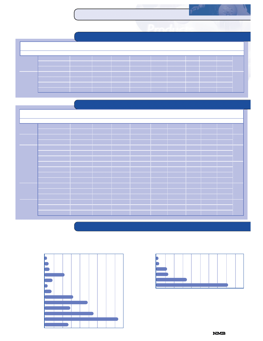
TABLE of CONTENTS
TOPIC
PAGE
Index . . . . . . . . . . . . . . . . . . . . . . . . . . . . . . . . . . . . . . . . . . . . . . . . . . . . . 4
Part Numbering System . . . . . . . . . . . . . . . . . . . . . . . . . . . . . . . . . . . . . . . . 6
HYBRID MOTORS
14PM-M 1.8º Hybrid . . . . . . . . . . . . . . . . . . . . . . . . . . . . . . . . . . . . . . . . . . 7
16PY-Q 0.9º Hybrid . . . . . . . . . . . . . . . . . . . . . . . . . . . . . . . . . . . . . . . . . . . 8
16PU-M 3.75º Hybrid . . . . . . . . . . . . . . . . . . . . . . . . . . . . . . . . . . . . . . . . . 9
17PM-K 1.8º Hybrid . . . . . . . . . . . . . . . . . . . . . . . . . . . . . . . . . . . . . . . . . 10
17PM-K 1.8º Hybrid Torque/Speed Characteristics . . . . . . . . . . . . . . . . . . . 11
17PW-M 1.875º Hybrid . . . . . . . . . . . . . . . . . . . . . . . . . . . . . . . . . . . . . . . 12
17PS-M 3.6º Hybrid . . . . . . . . . . . . . . . . . . . . . . . . . . . . . . . . . . . . . . . . . . 13
17PU-H 3.75º Hybrid . . . . . . . . . . . . . . . . . . . . . . . . . . . . . . . . . . . . . . . . 14
17PM-K 1.8º / 17PU-H 3.75º SMH (Sheet Metal Hybrid) . . . . . . . . . . . . . . . 15
23LY-C 0.9º Hybrid . . . . . . . . . . . . . . . . . . . . . . . . . . . . . . . . . . . . . . . . . . 16
23LM-C 1.8º Hybrid . . . . . . . . . . . . . . . . . . . . . . . . . . . . . . . . . . . . . . . . . 17
23LM-K 1.8º Hybrid (Microstep/Low Noise Series) . . . . . . . . . . . . . . . . . . . 18
23KM-C 1.8º Hybrid (High Torque) . . . . . . . . . . . . . . . . . . . . . . . . . . . . . . 19
23KM-K 1.8º Hybrid (High Torque/Microstep) . . . . . . . . . . . . . . . . . . . . . . 20
23LQ-C 5º Hybrid . . . . . . . . . . . . . . . . . . . . . . . . . . . . . . . . . . . . . . . . . . . 21
34PM-C 1.8º Hybrid . . . . . . . . . . . . . . . . . . . . . . . . . . . . . . . . . . . . . . . . . 22
PERMANENT MAGNET MOTORS
06BJ-H 18º Permanent Magnet . . . . . . . . . . . . . . . . . . . . . . . . . . . . . . . . . . 23
08BJ-H 18º Permanent Magnet . . . . . . . . . . . . . . . . . . . . . . . . . . . . . . . . . . 24
15BA-H 15º Permanent Magnet . . . . . . . . . . . . . . . . . . . . . . . . . . . . . . . . . 25
15BB-H 7.5º Permanent Magnet . . . . . . . . . . . . . . . . . . . . . . . . . . . . . . . . . 26
17BB-H 7.5º Permanent Magnet . . . . . . . . . . . . . . . . . . . . . . . . . . . . . . . . . 27
23BB-H 7.5º Permanent Magnet . . . . . . . . . . . . . . . . . . . . . . . . . . . . . . . . . 28
Motor Terminology . . . . . . . . . . . . . . . . . . . . . . . . . . . . . . . . . . . . . . . . . . 29
Conversion Tables . . . . . . . . . . . . . . . . . . . . . . . . . . . . . . . . . . . . . . . . . . . 31
Switching Sequence Tables . . . . . . . . . . . . . . . . . . . . . . . . . . . . . . . . . . . . . 31
Ordering Information & Warranty . . . . . . . . . . . . . . . . . . . . . . . . . . . . . . . 31
Worldwide Sales Office Listing . . . . . . . . . . . . . . . . . . . . . . . . . . . . back cover
818-341-0820
CORPORATION

IIN
ND
DE
EX
X
INDEX
HYBRID MOTORS
1.4”
14PM-M204
1.8
12.00
0.18
65.0
24.0
330
5
11.0
0.060
14PM-M206
1.8
5.20
0.40
13.0
4.8
330
5
11.0
0.060
7
1.6”
16PY-Q207
0.9
10.00
0.25
40.0
8.5
380
5
13.0
0.071
16PY-Q204
0.9
3.96
0.90
4.4
1.6
500
7
13.0
0.071
8
16PU-M003
3.75
4.20
0.70
6.0
4.0
700
10
17.0
0.093
16PU-M006
3.75
7.60
0.40
19.5
10.5
700
10
17.0
0.093
9
1.7”
17PM-K016V
1.8
8.80
0.40
22.0
19.5
1,500
21
34.0
0.186
17PM-K017V
1.8
4.40
0.80
5.5
5.7
1,500
21
34.0
0.186
17PM-K018V
1.8
3.00
1.20
2.5
2.8
1,500
21
34.0
0.186
17PM-K316V
1.8
9.60
0.40
24.0
25.8
1,700
24
45.0
0.246
17PM-K301V
1.8
4.80
0.80
6.0
7.1
1,700
24
45.0
0.246
17PM-K303V
1.8
3.20
1.20
2.7
3.3
1,700
24
45.0
0.246
17PM-K111V
1.8
10.00
0.40
25.0
33.4
2,200
31
56.0
0.306
17PM-K101V
1.8
5.00
0.80
6.2
8.6
2,200
31
56.0
0.306
17PM-K103V
1.8
3.60
1.20
3.0
4.4
2,200
31
56.0
0.306
17PM-K402V*
1.8
6.00
0.80
7.5
7.0
3,400
47
75.0
0.410
10-11
17PW-M003
1.875
4.90
0.65
7.5
6.2
1,200
17
17.0
0.093
12
17PS-M001V
3.6
3.20
0.40
7.9
5.4
450
6
17.0
0.093
13
17PU-H008V
3.75
3.70
0.90
4.1
2.9
600
8
34.0
0.186
17PU-H01OV
3.75
4.80
0.80
6.0
3.4
750
10
34.0
0.186
17PU-H309V
3.75
6.10
0.80
7.6
5.2
1,000
14
45.0
0.246
17PU-H312V
3.75
9.50
0.50
19.0
17.0
1,000
14
45.0
0.246
14
17PM-K204VT**
1.8
2.40
0.80
3.0
2.6
1,250
17
28.0
0.153
17PM-K018VT**
1.8
3.50
1.00
3.5
2.7
1,700
24
34.0
0.186
17PU-H204VT**
3.75
2.40
0.80
3.0
2.1
750
10
28.0
0.153
17PU-H018VT**
3.75
3.50
1.00
3.5
2.0
1,150
16
34.0
0.186
15
2.3”
23LY-C205
0.9
4.00
1.10
3.6
5.3
3,000
42
55.0
0.301
23LY-C201
0.9
5.50
0.78
7.1
8.3
3,000
42
55.0
0.301
23LY-C202
0.9
3.75
1.25
3.0
4.5
3,000
42
55.0
0.301
23LY-C301
0.9
3.00
1.70
1.8
4.5
4,000
56
110.0
0.601
23LY-C303
0.9
5.10
1.00
5.1
13.0
4,000
56
110.0
0.601
23LY-C305
0.9
6.00
0.85
7.1
18.0
4,000
56
110.0
0.601
23LY-C002
0.9
4.30
1.60
2.7
7.2
4,800
67
160.0
0.875
23LY-C001
0.9
8.50
0.85
10.0
30.0
4,800
67
160.0
0.875
16
23LM-C25OV
1.8
3.00
1.50
2.0
2.5
3,200
44
55.0
0.301
23LM-C213V
1.8
2.20
2.00
1.1
1.3
3,200
44
55.0
0.301
23LM-C343V
1.8
3.30
1.50
2.2
3.5
4,300
60
110.0
0.601
23LM-C355V
1.8
2.50
2.00
1.25
2.3
4,300
60
110.0
0.601
23LM-C047V
1.8
4.70
1.50
3.1
6.1
5,200
72
160.0
0.875
23LM-C055V
1.8
3.40
2.00
1.7
3.5
5,200
72
160.0
0.875
17
23LM-K250V
1.8
3.00
1.50
2.0
3.0
2,400
33
55.0
0.301
23LM-K213V
1.8
2.20
2.00
1.1
1.6
2,400
33
55.0
0.301
23LM-K343V
1.8
3.30
1.50
2.2
3.9
3,400
47
110.0
0.601
23LM-K355V
1.8
2.50
2.00
1.25
2.6
3,400
47
110.0
0.601
23LM-K047V
1.8
4.70
1.50
3.1
6.5
4,000
56
160.0
0.875
23LM-K055V
1.8
3.40
2.00
1.7
3.7
4,000
56
160.0
0.875
18
23KM-C250V
1.8
3.30
1.50
2.2
2.6
4,400
61
150.0
0.820
23KM-C379V
1.8
4.10
1.50
2.7
3.6
8,000
111
230.0
1.257
23KM-C032V
1.8
5.10
1.50
3.4
5.4
9,500
132
280.0
1.530
23KM-C716V
1.8
6.30
1.50
4.2
6.8
14,000
194
440.0
2.405
19
23KM-K250V
1.8
3.30
1.50
2.2
3.1
3,700
51
150.0
0.820
23KM-K379V
1.8
4.10
1.50
2.7
4.2
5,600
78
230.0
1.257
23KM-K032V
1.8
5.10
1.50
3.4
6.4
7,400
103
280.0
1.531
23KM-K716V
1.8
6.30
1.50
4.2
8.0
12,000
167
440.0
2.405
20
Motor
Model
Step
Rated
Rated
Winding
Induc-
Holding
Rotor
Diameter
Number
Angle
Voltage
Current
Resistance
tance
Torque
Inertia
Page
Inches
Degrees
Volts
Amps
Ohms
mH
g-cm
oz-in
g-cm
2
oz-in
2
4
IIN
ND
DE
EX
X
INDEX
HYBRID MOTORS (cont’d.)
0.6”
06BJ-H005
18.0
5.0
0.25
20.0
7.0
27
0
0.06
0.0003
06BJ-H012
18.0
12.0
0.12
100.0
37.0
30
0
0.06
0.0003
23
0.8”
08BJ-H007
18.0
3.8
0.19
20.0
7.0
40
1
0.2
0.001
08BJ-H040
18.0
2.1
0.35
6.0
5.0
40
1
0.2
0.001
24
1.5”
15BA-H051P
15.0
8.0
0.23
35.0
18.0
165
2
4.0
0.022
15BA-H073P
15.0
4.0
0.40
10.0
5.0
155
2
4.0
0.022
15BA-H043P
15.0
2.0
0.80
2.5
3.4
220
3
4.0
0.022
25
15BB-H051P
7.5
8.0
0.23
35.0
27.0
165
2
4.0
0.022
15BB-H073P
7.5
4.0
0.40
10.0
6.7
155
2
4.0
0.022
15BB-H170P
7.5
6.6
0.22
30.0
17.0
190
3
1.5
0.008
15BB-H043P
7.5
2.0
0.80
2.5
4.5
205
3
4.0
0.022
26
1.7”
17BB-H262P
7.5
5.4
0.45
12.0
11.0
500
7
12.0
0.066
17BB-H267P
7.5
7.5
0.30
25.0
19.0
480
7
12.0
0.066
17BB-H240P
7.5
5.4
0.45
12.0
27.0
670
9
12.0
0.066
27
2.3”
23BB-H251P
7.5
5.0
0.75
6.6
9.0
1,200
17
30.0
0.164
23BB-H252P
7.5
12.0
0.34
36.0
32.0
1,200
17
30.0
0.164
23BB-H246P
7.5
4.9
0.75
6.5
17.0
1,400
19
30.0
0.164
28
2.3”
23LQ-C202V
5.0
3.90
1.10
3.5
4.0
2,300
32
55.0
0.301
(cont’d.)
23LQ-C309V
5.0
6.75
1.00
6.75
8.6
3,100
43
110.0
0.601
23LQ-C055V
5.0
3.40
2.00
1.7
2.7
3,600
50
160.0
0.875
21
3.4”
34PM-C101
1.8
3.00
4.00
0.75
3.5
20,000
278
1,100.0
6.014
34PM-C108
1.8
12.00
1.00
12.0
56.0
20,000
278
1,100.0
6.014
34PM-C007
1.8
5.50
1.25
4.4
14.5
12,000
167
560.0
3.062
34PM-C049
1.8
1.70
4.70
0.36
1.7
12,000
167
560.0
3.062
22
*NMB’s new 17 size high-torque motor **NMB’s new sheet metal hybrid (SMH) motor series
PERMANENT MAGNET MOTORS
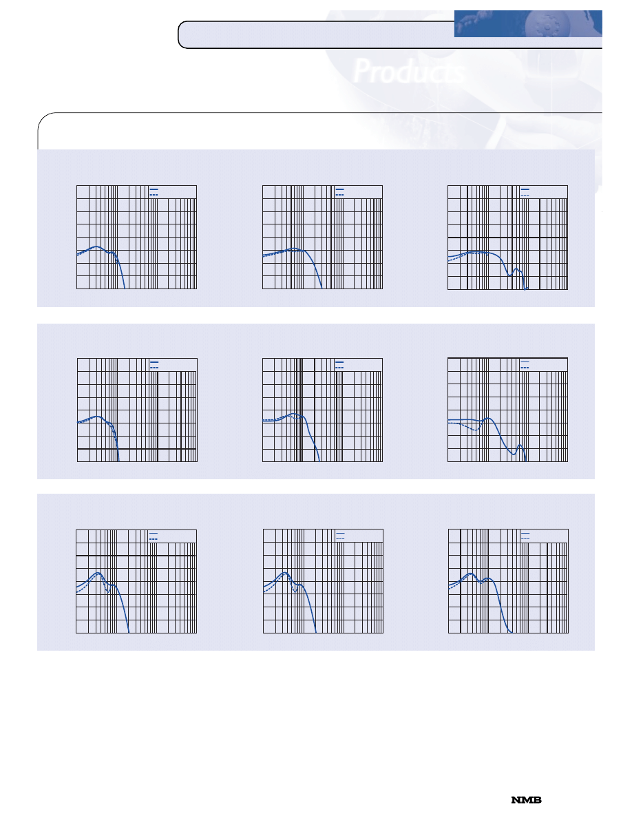
STEP MOTOR PERFORMANCE
Model
14PM-M (1.8°)
16PY-Q (0.9°)
16PU-M (3.75°)
17PM-K (1.8°)
17PW-M (1.875°)
17PS-M (3.6°)
17PU-H (3.75°)
23LY-C (0.9°)
23LM-C (1.8°)
23LM-K (1.8°)
23KM-C (1.8°)
23KM-K (1.8°)
23LQ-C (5°)
Motor
Model
Step
Rated
Rated
Winding
Induc-
Holding
Rotor
Diameter
Number
Angle
Voltage
Current
Resistance
tance
Torque
Inertia
Page
Inches
Degrees
Volts
Amps
Ohms
mH
g-cm
oz-in
g-cm
2
oz-in
2
(oz-in)
0
20
40
60
80
100
120
140
160
180
Holding Torque Range
Hybrid Type
Model
06BJ-H (18°)
08BJ-H (18°)
15BA-H (15°)
15BB-H (7.5°)
17BB-H (7.5°)
23BB-H (7.5°)
(oz-in)
0
2
4
6
8
10
12
14
16
18
20
Permanent Magnet Type
Motor
Model
Step
Rated
Rated
Winding
Induc-
Holding
Rotor
Diameter
Number
Angle
Voltage
Current
Resistance
tance
Torque
Inertia
Page
Inches
Degrees
Volts
Amps
Ohms
mH
g-cm
oz-in
g-cm
2
oz-in
2
818-341-0820
CORPORATION
0.9
1.8
1.875
3.6
3.75
5
7.5
15
18
Step
Angle
(Degree)
CUSTOM FEATURES
P
PA
AR
RT
T
N
NU
UM
MB
BE
ER
RIIN
NG
G
S
S
Y
YS
S
T
T
E
EM
M
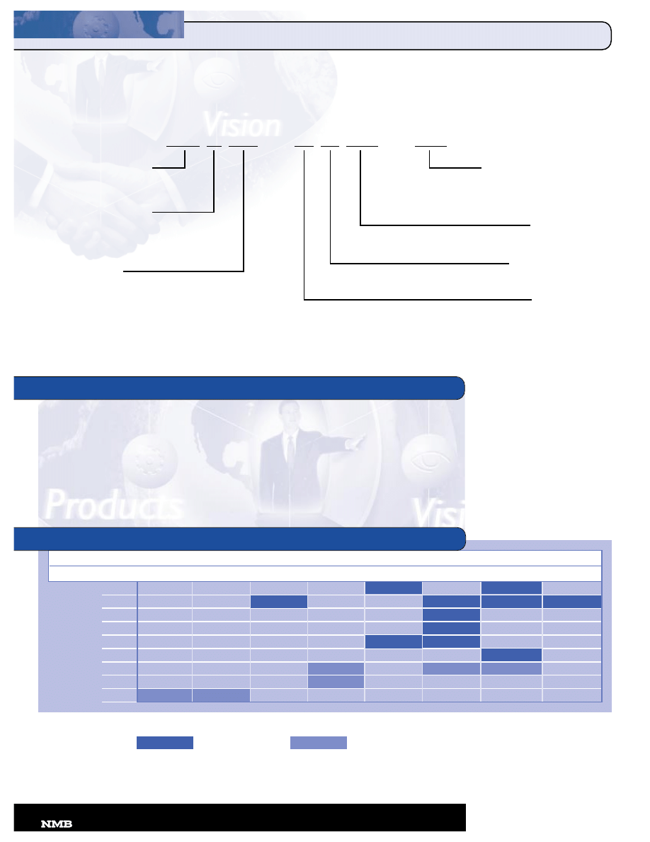
PART NUMBERING SYSTEM
NMB will modify the step motors in this catalog to meet your
application-specific requirements by customizing these features:
• Pulley/Gears
• Windings
• Re-Wire Ends
• Shaft
• Connector or Wire On Lead
• Termination
• Mount
• Tapped Encoder Holes
Size (x 0.1 inch)
06
08
14
15
16
17
23
34
Size (mm)
15
20
34
35
39
42
56
86
SIZE/STEP ANGLE MATRIX
23 L M - K 0 01 - 01
Size
Motor O.D. in tenths of an inch.
(Example: Size 23 = 2.3” Dia.)
Type
B = Permanent Magnet
L = Precision, Hybrid
K = Precision, Hybrid
P = Precision, Hybrid
Step Angle
A =
15°
B =
7.5°
J =
18°
M =
1.8°
Q =
5.0°
S =
3.6°
U = 3.75°
W = 1.875°
Y =
0.9°
Versions
01 to 99 = standard
L1 to L9 = with leadscrew
G1 to G9 = with gear
P1 to P9 = with pulley
Different Windings
01 to 99
Motor Lengths
0 to 9
Motor Construction
C = 2 & 4 phase Hybrid
H = 2 & 4 phase PM
K = 2 & 4 phase Hybrid
M = 2 & 4 phase Hybrid
Q = 2 & 4 phase Hybrid
Hybrid Type
Permanent Magnet Type
6
CORPORATION
•
818-341-0820
TORQUE/SPEED CHARACTERISTICS
PULL OUT TORQUE
(N
•
m
x
10
-4
)
700
600
500
400
300
200
100
0
100 1K 10K 100K
(PPS)
WINDING
DIAGRAM
GENERAL SPECIFICATIONS
1
14
4
P
PM
M--M
M 1
1..8
8
ºº
H
HY
YB
BR
RIID
D
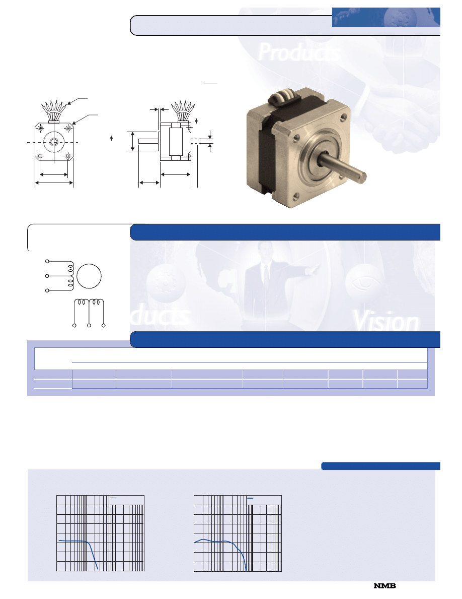
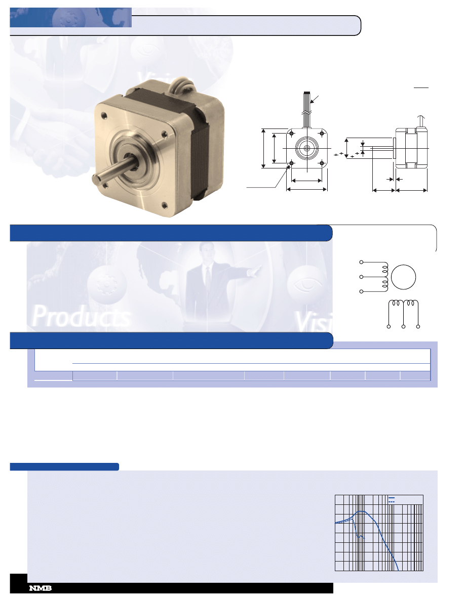
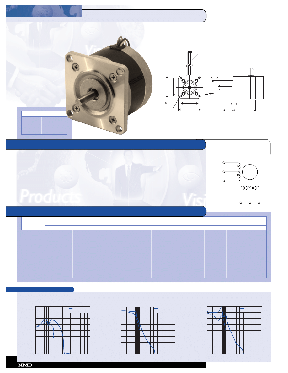
14PM-M 1.8
º
HYBRID
Step Angle ........................................................................ 1.8º
Step Angle Accuracy ..................................................... +/-5%
Temperature Rise.................................................. 80º C Max.
Ambient Temperature Range ........................... -20º to +50º C
Insulation Resistance......................... 100M
Ω
Min., 500 VDC
Dielectric Strength................................... 500 VAC for 1 min.
Radial Play.................................. 0.02 mm Max. (450 g-load)
End Play ..................................... 0.08 mm Max. (450 g-load)
Switching Sequence............................................. See page 31
Rated
Rated Current/
Winding Resistance/
Holding
Rotor
Detent
Model
Voltage
Phase
Phase
Torque
Inductance
Inertia
Torque
Weight
Number
V
A
Ω
g-cm
mH
g-cm
2
g-cm
g
14PM-M204
12.0
0.18
65.0
330
24.0
11.0
50
110
14PM-M206
5.2
0.4
13.0
330
4.8
11.0
50
110
MODEL SPECIFICATIONS
RED
BLACK
YELLOW
BLUE
WHITE
ORANGE
1.02 (26)
1.38 (35)
LEAD WIRE UL 3266
AWG 26
11.8 (300) MIN
4-M3 x 0.5
MIN .135 (3.5) DP
.067
(1.7)
Unit:
inches
(mm)
1.03 MAX
(26)
.95 (24)
.013
)
.1969
+
.0000
-
.0005
(5
+
.000
-
)
.05
.866
+
.000
-
.002
(22
+
.00
-
818-341-0820
CORPORATION
Model: 14PM-M206
Driver: Unipolar Chopper Dual • Supply Voltage: 24.0 (Volt)
Drive Current: 0.40 (A/WDG) • Load Inertia: 34.0 (g-cm
2
)
PULL OUT TORQUE
(N
•
m
x
10
-4
)
700
600
500
400
300
200
100
0
100 1K 10K 100K
(PPS)
Model: 14PM-M204
Driver: Unipolar Chopper Dual • Supply Voltage: 24.0 (Volt)
Drive Current: 0.18 (A/WDG) • Load Inertia: 34.0 (g-cm
2
)
WINDING
DIAGRAM
GENERAL SPECIFICATIONS
1
16
6
P
PY
Y--Q
Q 0
0..9
9
ºº
H
HY
YB
BR
RIID
D
16PY-Q 0.9
º
HYBRID
Step Angle ....................................................................... 0.9º
Step Angle Accuracy ..................................................... +/-5%
Temperature Rise.................................................. 80º C Max.
Ambient Temperature Range ........................... -20º to +50º C
Insulation Resistance......................... 100M
Ω
Min., 500 VDC
Dielectric Strength................................... 500 VAC for 1 min.
Radial Play.................................. 0.02 mm Max. (450 g-load)
End Play ..................................... 0.08 mm Max. (450 g-load)
Switching Sequence............................................ See page 31
Rated
Rated Current/
Winding Resistance/
Holding
Rotor
Detent
Model
Voltage
Phase
Phase
Torque
Inductance
Inertia
Torque
Weight
Number
V
A
Ω
g-cm
mH
g-cm
2
g-cm
g
16PY-Q207
10.00
0.25
40.00
380
8.5
13.0
30
120
16PY-Q204
3.96
0.90
4.40
500
1.6
13.0
30
120
MODEL SPECIFICATIONS
RED
BLACK
YELLOW
BLUE
WHITE
ORANGE
Model: 16PY-Q204
Driver: Unipolar Chopper Dual • Supply Voltage: 24.0 (Volt)
Drive Current: 0.90 (A/WDG) • Load Inertia: 34.0 (g-cm
2
)
Model: 16PY-Q207
Driver: Unipolar Chopper Dual • Supply Voltage: 24.0 (Volt)
Drive Current: 0.25 (A/WDG) • Load Inertia: 34.0 (g-cm
2
)
1.22 (31)
1.57 (40)
LEAD WIRE UL 3266
AWG 26
11.8 (300) MIN
4-M3 x 0.5
MIN .135 (3.5) DP
.08
(2)
Unit:
inches
(mm)
1.03 MAX
(26)
.95 (24)
.013
)
.1969
+
.0000
-
.0005
(5
+
.000
-
)
.05
.866
+
.000
-
.002
(22
+
.00
-
8
CORPORATION
•
818-341-0820
PULL OUT TORQUE
PULL IN TORQUE
(N
•
m
x
10
-4
)
700
600
500
400
300
200
100
0
100 1K 10K 100K
(PPS)
PULL OUT TORQUE
PULL IN TORQUE
(N
•
m
x
10
-4
)
700
600
500
400
300
200
100
0
100 1K 10K 100K
(PPS)
TORQUE/SPEED CHARACTERISTICS
TORQUE/SPEED CHARACTERISTICS
WINDING
DIAGRAM
GENERAL SPECIFICATIONS
1
16
6
P
PU
U--M
M 3
3
..7
7
5
5
ºº
H
HY
YB
BR
RIID
D
16PU-M 3.75
º
HYBRID
Step Angle ..................................................................... 3.75º
Step Angle Accuracy ..................................................... +/-5%
Temperature Rise.................................................. 80º C Max.
Ambient Temperature Range ........................... -20º to +50º C
Insulation Resistance......................... 100M
Ω
Min., 500 VDC
Dielectric Strength................................... 500 VAC for 1 min.
Radial Play.................................. 0.02 mm Max. (450 g-load)
End Play ..................................... 0.08 mm Max. (450 g-load)
Switching Sequence............................................ See page 31
Rated
Rated Current/
Winding Resistance/
Holding
Rotor
Detent
Model
Voltage
Phase
Phase
Torque
Inductance
Inertia
Torque
Weight
Number
V
A
Ω
g-cm
mH
g-cm
2
g-cm
g
16PU-M003
4.20
0.70
6.0
700
4.0
17.0
110
175
16PU-M006
7.60
0.40
19.5
700
10.5
17.0
110
175
MODEL SPECIFICATIONS
RED
BLACK
YELLOW
BLUE
WHITE
ORANGE
PULL OUT TORQUE
PULL IN TORQUE
(N
•
m
x
10
-4
)
700
600
500
400
300
200
100
0
100 1K 10K 100K
(PPS)
Model: 16PU-M006
Driver: Unipolar Chopper Dual • Supply Voltage: 24.0 (Volt)
Drive Current: 0.40 (A/WDG) • Load Inertia: 34.0 (g-cm
2
)
PULL OUT TORQUE
PULL IN TORQUE
(N
•
m
x
10
-4
)
700
600
500
400
300
200
100
0
100 1K 10K 100K
(PPS)
Model: 16PU-M003
Driver: Unipolar Chopper Dual • Supply Voltage: 24.0 (Volt)
Drive Current: 0.70 (A/WDG) • Load Inertia: 34.0 (g-cm
2
)
(
)
LEAD WIRE UL3266
AWG 26
11.8 (300) MIN
Unit:
inches
(mm)
.1
8
6
9
+
.0
0
0
0
-
.0
0
0
5
.8
6
6
+
.0
0
0
-
.0
0
2
2
2
+
.0
0
-
.0
5
(
)
5
+
0
.0
0
0
-
0
.0
1
3
1
.5
4
(
3
9
)
1
.2
2
(
3
1
)
4-M3 x 0.5
MIN .157 (4) DP
1.22 (31)
1.54 (39)
.95
(24)
.08 (2)
1.18 MAX
(30)
818-341-0820
CORPORATION
WINDING
DIAGRAM
1
17
7
P
PM
M--K
K 1
1..8
8
ºº
H
HY
YB
BR
RIID
D
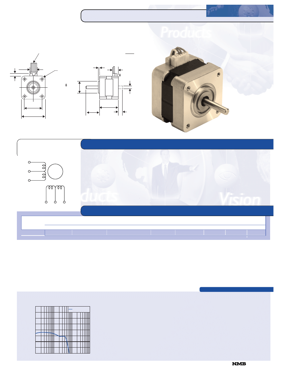
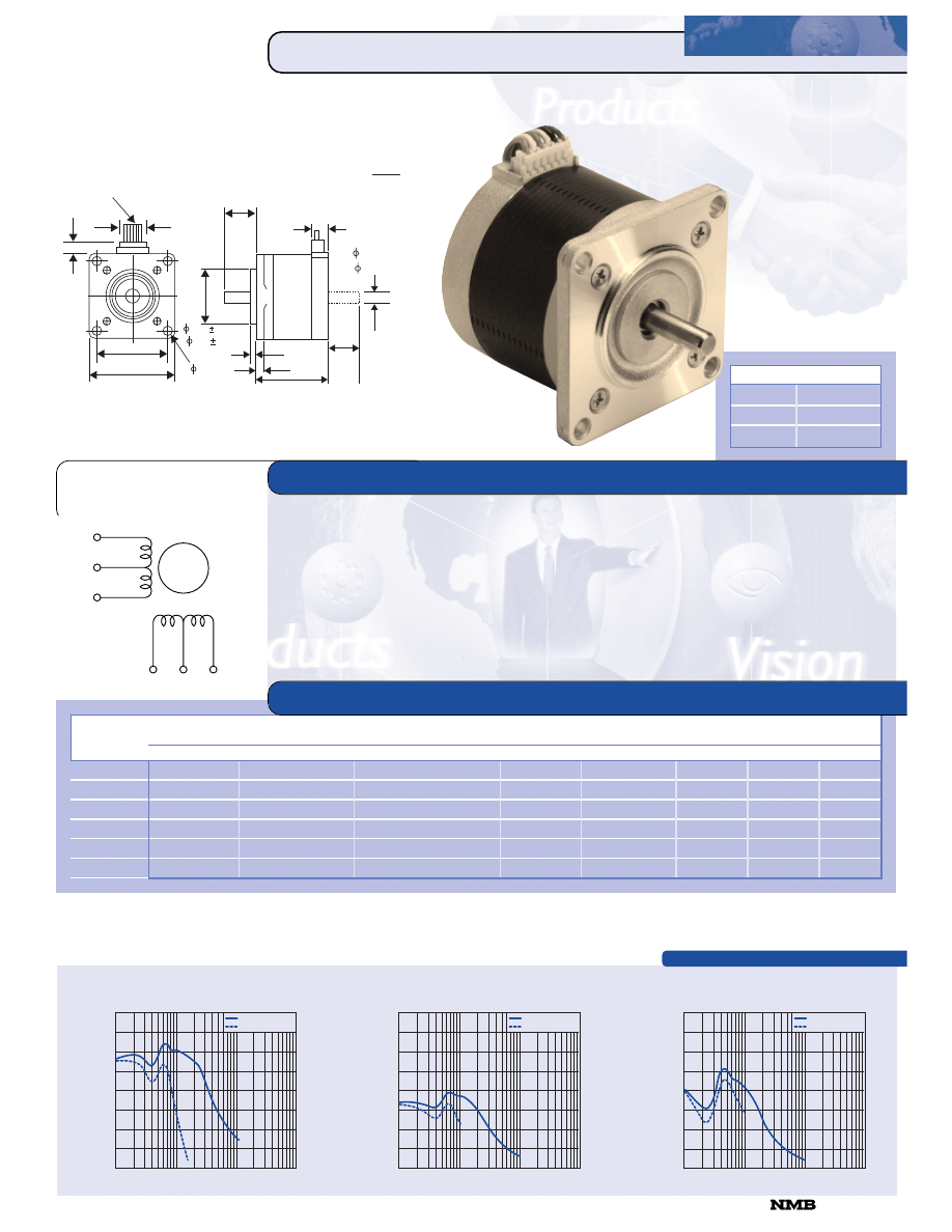
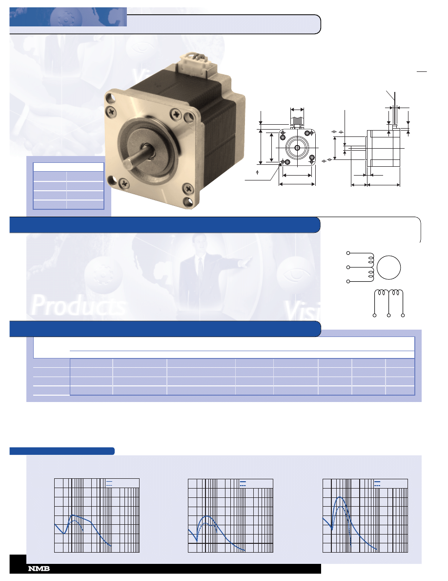
17PM-K 1.8
º
HYBRID
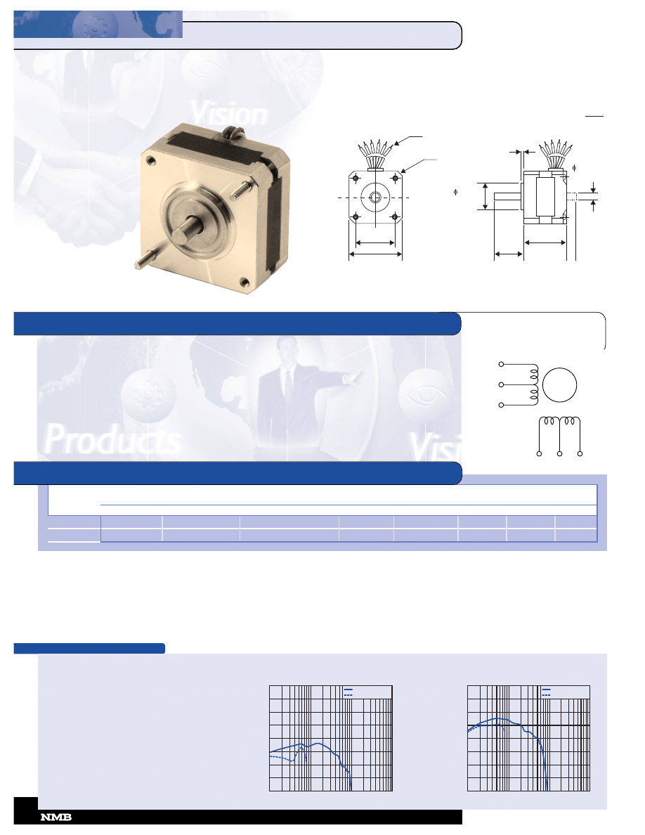
Step Angle ....................................................................... 1.8º
Step Angle Accuracy ..................................................... +/-5%
Temperature Rise.................................................. 80º C Max.
Ambient Temperature Range ........................... -20º to +50º C
Insulation Resistance......................... 100M
Ω
Min., 500 VDC
Dielectric Strength................................... 500 VAC for 1 min.
Radial Play.................................. 0.02 mm Max. (450 g-load)
End Play ..................................... 0.08 mm Max. (450 g-load)
Switching Sequence............................................ See page 31
Rated
Rated Current/
Winding Resistance/
Holding
Rotor
Detent
Model
Voltage
Phase
Phase
Torque
Inductance
Inertia
Torque
Weight
Number
V
A
Ω
g-cm
mH
g-cm
2
g-cm
g
17PM-K016V
8.80
0.40
22.00
1,500
19.5
34.0
80
200
17PM-K017V
4.40
0.80
5.50
1,500
5.7
34.0
80
200
17PM-K018V
3.00
1.20
2.50
1,500
2.8
34.0
80
200
17PM-K316V
9.60
0.40
24.00
1,700
25.8
45.0
100
250
17PM-K301V
4.80
0.80
6.00
1,700
7.1
45.0
100
250
17PM-K303V
3.20
1.20
2.70
1,700
3.3
45.0
100
250
17PM-K111V
10.00
0.40
25.00
2,200
33.4
56.0
120
300
17PM-K101V
5.00
0.80
6.20
2,200
8.6
56.0
120
300
17PM-K103V
3.60
1.20
3.00
2,200
4.4
56.0
120
300
17PM-K402V
6.00
0.80
7.50
3,400
7.0
75.0
200
350
MODEL SPECIFICATIONS
RED
BLACK
YELLOW
BLUE
WHITE
ORANGE
1.22 (31)
1.65 (42)
.24
(6)
LEAD WIRE UL 1007
AWG 24
11.8 (300) MIN
.61
(15.5)
4-M3 x 0.5
MIN .157 DP
.08
(2)
.95
.013
)
.1969
+.0000
- .0005
(5
+.000
-
)
.05
.866
+
.000
-
.002
(22
+
.00
-
(24)
.315
(8)
.41
(10.5)
Unit:
inches
(mm)
10
CORPORATION
•
818-341-0820
17PM-K0XX
1.34 (34)
17PM-K3XX
1.50 (38.1)
17PM-K1XX
1.57 (42.1)
17PM-K4XX
1.85 (47)
P/N
“L”
GENERAL SPECIFICATIONS
1
17
7
P
PM
M--K
K 1
1..8
8
ºº
H
HY
YB
BR
RIID
D
TORQUE/SPEED CHARACTERISTICS
PULL OUT TORQUE
PULL IN TORQUE
(N
•
m
x
10
-4
)
3500
3000
2500
2000
1500
1000
500
0
100 1K 10K 100K
(PPS)
17PM-K 1.8
º
HYBRID
Model: 17PM-K017V
Driver: Unipolar Chopper Dual • Supply Voltage: 24.0 (Volt)
Drive Current: 0.80 (A/WDG) • Load Inertia: 34.0 (g-cm
2
)
PULL OUT TORQUE
PULL IN TORQUE
(N
•
m
x
10
-4
)
3500
3000
2500
2000
1500
1000
500
0
100 1K 10K 100K
(PPS)
Model: 17PM-K016V
Driver: Unipolar Chopper Dual • Supply Voltage: 24.0 (Volt)
Drive Current: 0.40 (A/WDG) • Load Inertia: 34.0 (g-cm
2
)
Model: 17PM-K303V
Driver: Unipolar Chopper Dual • Supply Voltage: 24.0 (Volt)
Drive Current: 1.20 (A/WDG) • Load Inertia: 34.0 (g-cm
2
)
Model: 17PM-K301V
Driver: Unipolar Chopper Dual • Supply Voltage: 24.0 (Volt)
Drive Current: 0.80 (A/WDG) • Load Inertia: 34.0 (g-cm
2
)
PULL OUT TORQUE
PULL IN TORQUE
(N
•
m
x
10
-4
)
3500
3000
2500
2000
1500
1000
500
0
100 1K 10K 100K
(PPS)
Model: 17PM-K316V
Driver: Unipolar Chopper Dual • Supply Voltage: 24.0 (Volt)
Drive Current: 0.40 (A/WDG) • Load Inertia: 34.0 (g-cm
2
)
PULL OUT TORQUE
PULL IN TORQUE
(N
•
m
x
10
-4
)
3500
3000
2500
2000
1500
1000
500
0
100 1K 10K 100K
(PPS)
Model: 17PM-K103V
Driver: Unipolar Chopper Dual • Supply Voltage: 24.0 (Volt)
Drive Current: 1.20 (A/WDG) • Load Inertia: 34.0 (g-cm
2
)
PULL OUT TORQUE
PULL IN TORQUE
(N
•
m
x
10
-4
)
3500
3000
2500
2000
1500
1000
500
0
100 1K 10K 100K
(PPS)
Model: 17PM-K101V
Driver: Unipolar Chopper Dual • Supply Voltage: 24.0 (Volt)
Drive Current: 0.80 (A/WDG) • Load Inertia: 34.0 (g-cm
2
)
Model: 17PM-K111V
Driver: Unipolar Chopper Dual • Supply Voltage: 24.0 (Volt)
Drive Current: 0.40 (A/WDG) • Load Inertia: 34.0 (g-cm
2
)
PULL OUT TORQUE
PULL IN TORQUE
(N
•
m
x
10
-4
)
3500
3000
2500
2000
1500
1000
500
0
100 1K 10K 100K
(PPS)
Model: 17PM-K018V
Driver: Unipolar Chopper Dual • Supply Voltage: 24.0 (Volt)
Drive Current: 1.20 (A/WDG) • Load Inertia: 34.0 (g-cm
2
)
818-341-0820
CORPORATION
PULL OUT TORQUE
PULL IN TORQUE
(N
•
m
x
10
-4
)
3500
3000
2500
2000
1500
1000
500
0
100 1K 10K 100K
(PPS)
PULL OUT TORQUE
PULL IN TORQUE
(N
•
m
x
10
-4
)
3500
3000
2500
2000
1500
1000
500
0
100 1K 10K 100K
(PPS)
PULL OUT TORQUE
PULL IN TORQUE
(N
•
m
x
10
-4
)
3500
3000
2500
2000
1500
1000
500
0
100 1K 10K 100K
(PPS)
TORQUE/SPEED CHARACTERISTICS
WINDING
DIAGRAM
GENERAL SPECIFICATIONS
1
17
7
P
PW
W--M
M 1
1..8
87
7
5
5
ºº
H
HY
YB
BR
RIID
D
17PW-M 1.875
º
HYBRID
Step Angle ................................................................... 1.875º
Step Angle Accuracy ..................................................... +/-5%
Temperature Rise.................................................. 80º C Max.
Ambient Temperature Range ........................... -20º to +50º C
Insulation Resistance......................... 100M
Ω
Min., 500 VDC
Dielectric Strength................................... 500 VAC for 1 min.
Radial Play.................................. 0.02 mm Max. (450 g-load)
End Play ..................................... 0.08 mm Max. (450 g-load)
Switching Sequence............................................ See page 31
Rated
Rated Current/
Winding Resistance/
Holding
Rotor
Detent
Model
Voltage
Phase
Phase
Torque
Inductance
Inertia
Torque
Weight
Number
V
A
Ω
g-cm
mH
g-cm
2
g-cm
g
17PW-M003
4.9
0.65
7.5
1,200
6.2
17.0
250
200
MODEL SPECIFICATIONS
RED
BLACK
YELLOW
BLUE
WHITE
ORANGE
PULL OUT TORQUE
PULL IN TORQUE
(N
•
m
x
10
-4
)
1400
1200
1000
800
600
400
200
0
100 1K 10K 100K
(PPS)
Model: 17PW-M003
Driver: Unipolar Chopper Dual • Supply Voltage: 24.0 (Volt)
Drive Current: 0.65 (A/WDG) • Load Inertia: 34.0 (g-cm
2
)
(
)
LEAD WIRE UL3266
AWG 26
11.8 (300) MIN
Unit:
inches
(mm)
.1
9
6
9
+
.0
0
0
0
-
.0
0
0
5
.8
6
6
+
.0
0
0
-
.0
0
2
2
2
+
.0
0
-
.0
5
(
)
5
+
0
.0
0
0
-
0
.0
1
3
1
.6
5
(
4
2
)
1
.2
2
(
3
1
)
4-M3 x 0.5
MIN .157 (4) DP
1.22 (31)
1.65 (42)
.95
(24)
.08 (2)
1.18
(30) MAX
12
CORPORATION
•
818-341-0820
CORPORATION
•
818-341-0820
TORQUE/SPEED CHARACTERISTICS
WINDING
DIAGRAM
GENERAL SPECIFICATIONS
1
17
7
P
PS
S
--M
M 3
3
..6
6
ºº
H
HY
YB
BR
RIID
D
17PS-M 3.6
º
HYBRID
Step Angle ....................................................................... 3.6º
Step Angle Accuracy ..................................................... +/-5%
Temperature Rise.................................................. 80º C Max.
Ambient Temperature Range ........................... -20º to +50º C
Insulation Resistance......................... 100M
Ω
Min., 500 VDC
Dielectric Strength................................... 500 VAC for 1 min.
Radial Play.................................. 0.02 mm Max. (450 g-load)
End Play ..................................... 0.08 mm Max. (450 g-load)
Switching Sequence............................................ See page 31
Rated
Rated Current/
Winding Resistance/
Holding
Rotor
Detent
Model
Voltage
Phase
Phase
Torque
Inductance
Inertia
Torque
Weight
Number
V
A
Ω
g-cm
mH
g-cm
2
g-cm
g
17PS-M001V
3.2
0.4
7.9
450
5.4
17.0
50
200
MODEL SPECIFICATIONS
RED
BLACK
YELLOW
BLUE
WHITE
ORANGE
PULL OUT TORQUE
(N
•
m
x
10
-4
)
700
600
500
400
300
200
100
0
100 1K 10K 100K
(PPS)
Model: 17PS-M001V
Driver: Unipolar Chopper Dual • Supply Voltage: 24.0 (Volt)
Drive Current: 0.40 (A/WDG) • Load Inertia: 34.0 (g-cm
2
)
1.22 (31)
1.65 (42)
.24
(6)
LEAD WIRE UL 1007
AWG 24
11.8 (300) MIN
.61
(15.5)
4-M3 x 0.5
MIN .157 (4) DP
.08
(2)
Unit:
inches
(mm)
.95
.013
)
.1969
+
.0000
-
.0005
(5
+
.000
-
)
.05
.866
+
.000
-
.002
(22
+
.00
-
(24)
.315
(8)
.41
(10.5)
1.34
(34)
818-341-0820
CORPORATION
WINDING
DIAGRAM
GENERAL SPECIFICATIONS
1
17
7
P
PU
U--H
H 3
3
..7
7
5
5
ºº
H
HY
YB
BR
RIID
D
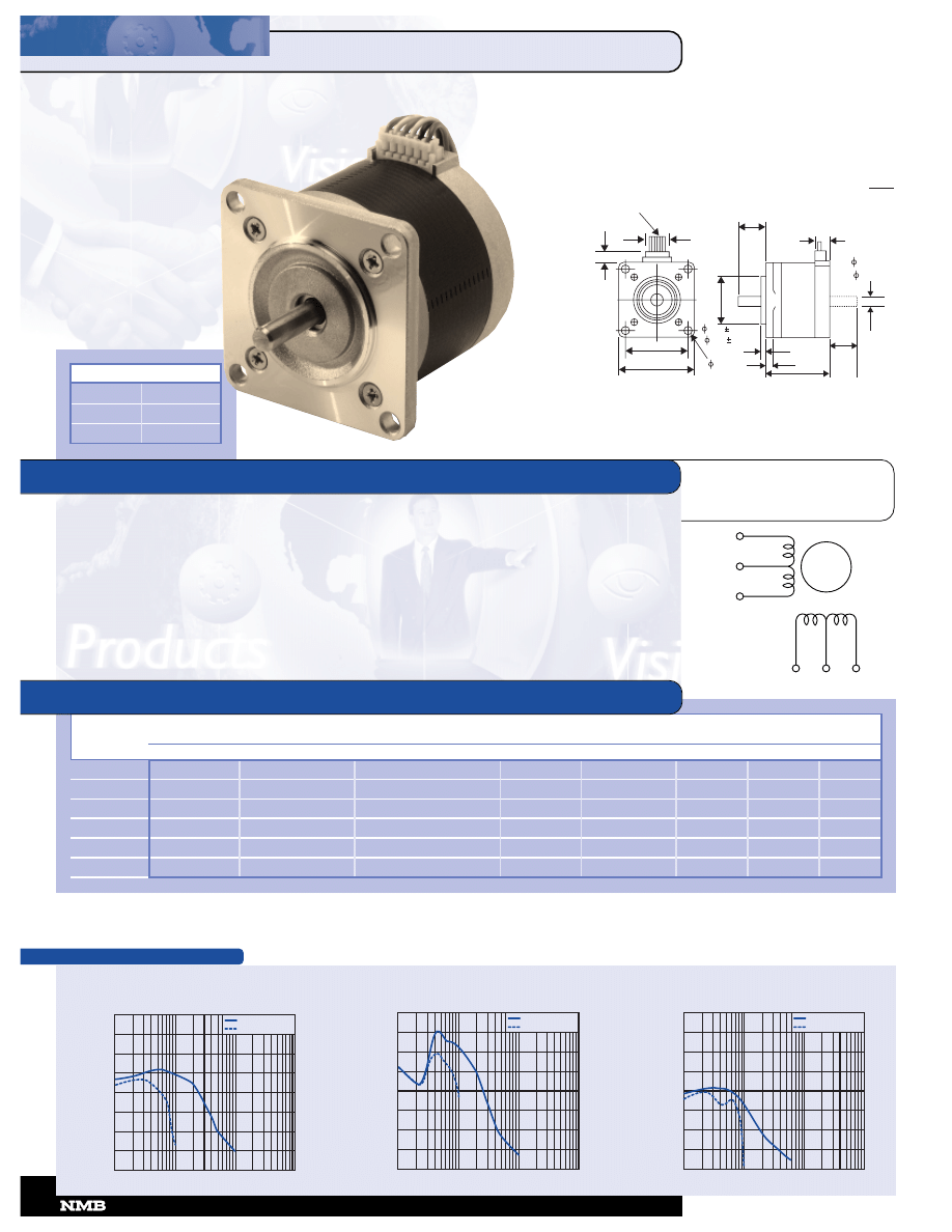
17PU-H 3.75
º
HYBRID
Step Angle ..................................................................... 3.75º
Step Angle Accuracy ..................................................... +/-5%
Temperature Rise.................................................. 80º C Max.
Ambient Temperature Range ........................... -20º to +50º C
Insulation Resistance......................... 100M
Ω
Min., 500 VDC
Dielectric Strength................................... 500 VAC for 1 min.
Radial Play.................................. 0.02 mm Max. (450 g-load)
End Play ..................................... 0.08 mm Max. (450 g-load)
Switching Sequence............................................ See page 31
Rated
Rated Current/
Winding Resistance/
Holding
Rotor
Detent
Model
Voltage
Phase
Phase
Torque
Inductance
Inertia
Torque
Weight
Number
V
A
Ω
g-cm
mH
g-cm
2
g-cm
g
17PU-H008V
3.70
0.90
4.10
600
2.9
34.0
180
200
17PU-H010V
4.80
0.80
6.00
750
3.4
34.0
180
200
17PU-H309V
6.10
0.80
7.60
1,000
5.2
45.0
250
250
17PU-H312V
9.50
0.50
19.00
1,000
17.0
45.0
250
250
MODEL SPECIFICATIONS
RED
BLACK
YELLOW
BLUE
WHITE
ORANGE
PULL OUT TORQUE
PULL IN TORQUE
(N
•
m
x
10
-4
)
1400
1200
1000
800
600
400
200
0
100 1K 10K 100K
(PPS)
Model: 17PU-H309V
Driver: Unipolar Chopper Dual • Supply Voltage: 24.0 (Volt)
Drive Current: 0.80 (A/WDG) • Load Inertia: 34.0 (g-cm
2
)
PULL OUT TORQUE
PULL IN TORQUE
(N
•
m
x
10
-4
)
700
600
500
400
300
200
100
0
100 1K 10K 100K
(PPS)
Model: 17PU-H010V
Driver: Unipolar Chopper Dual • Supply Voltage: 24.0 (Volt)
Drive Current: 0.80 (A/WDG) • Load Inertia: 34.0 (g-cm
2
)
0.013
)
.1969
+
.0000
-
.0005
( 5
+
0.000
-
)
0.05
.866
+
.000
-
.002
( 22
+
0.00
-
1.22 (31)
1.65 (42)
.24
(6)
LEAD WIRE UL 1007
AWG 24
11.8 (300) MIN
.61
(15.5)
4-M3 x 0.5
MIN .157 DP
.08
(2)
.95
(24)
.315
(8)
.41
(10.5)
Unit:
inches
(mm)
P/N
“L”
17PU-H0XX
1.34 (34)
17PU-H3XX
1.50 (38)
14
CORPORATION
•
818-341-0820
TORQUE/SPEED CHARACTERISTICS
TORQUE/SPEED CHARACTERISTICS
WINDING
DIAGRAM
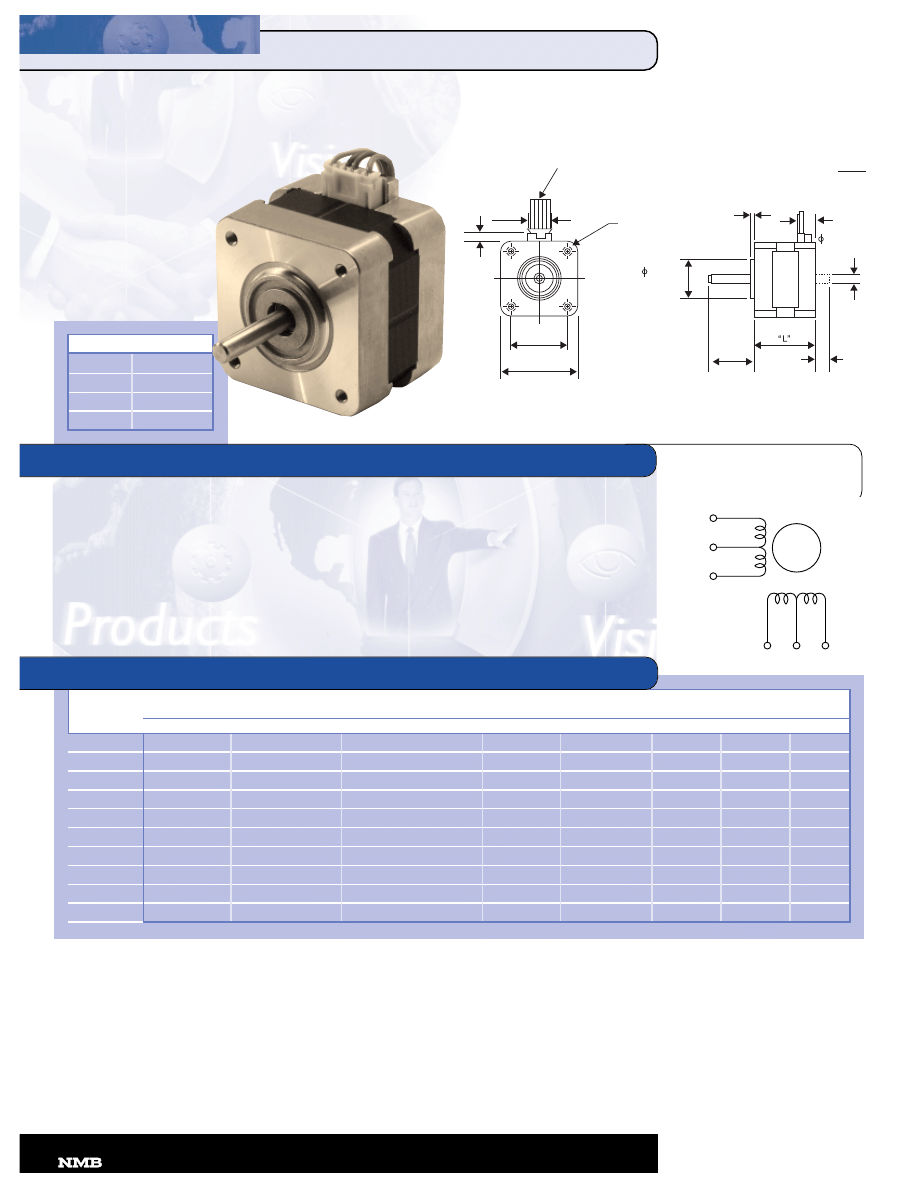
GENERAL SPECIFICATIONS
1
17
7
P
PM
M--K
K 1
1..8
8°°//1
17
7
P
PU
U--H
H
3
3
..7
7
5
5
ºº
S
S
M
MH
H H
HY
YB
BR
RIID
D
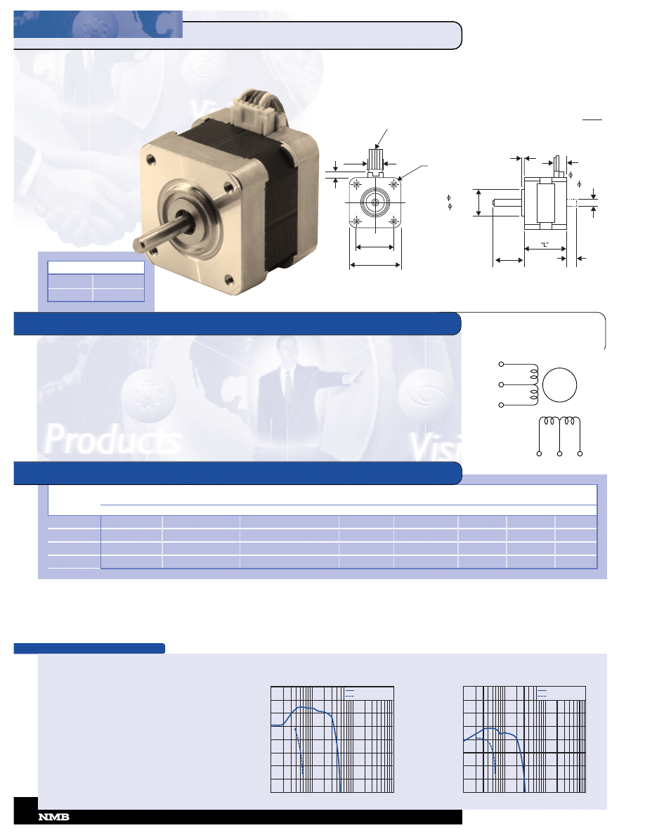
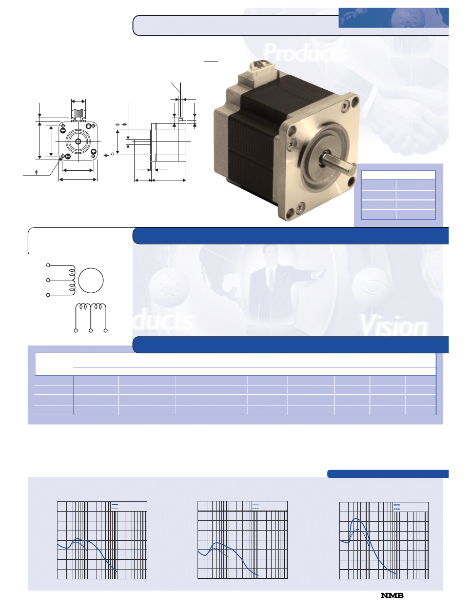
17PM-K 1.8
º
SMH HYBRID
17PU-H 3.75
º
SMH HYBRID
Step Angle Accuracy ..................................................... +/-5%
Temperature Rise.................................................. 80º C Max.
Ambient Temperature Range ........................... -20º to +50º C
Insulation Resistance......................... 100M
Ω
Min., 500 VDC
Dielectric Strength................................... 500 VAC for 1 min.
Radial Play.................................. 0.02 mm Max. (450 g-load)
End Play ..................................... 0.10 mm Max. (450 g-load)
Switching Sequence............................................ See page 31
Step
Rate
Rated Current/
Winding Resistance/
Holding
Rotor
Detent
Model
Angle
Voltage
Phase
Phase
Torque
Inductance
Inertia
Torque
Weight
Number
D
V
A
Ω
g-cm
mH
g-cm
2
g-cm
g
17PM-K204VT
1.8
2.40
0.8
3.0
1,250
2.6
28.0
60
180
17PM-K018VT
1.8
3.50
1.0
3.5
1,700
2.7
34.0
70
220
17PU-H204VT
3.75
2.40
0.8
3.0
750
2.1
28.0
120
180
17PU-H018VT
3.75
3.50
1.0
3.5
1,150
2.0
34.0
150
220
MODEL SPECIFICATIONS
RED
BLACK
YELLOW
BLUE
WHITE
ORANGE
PULL OUT TORQUE
PULL IN TORQUE
(N
•
m
x
10
-4
)
700
600
500
400
300
200
100
0
100 1K 10K 100K
(PPS)
PULL OUT TORQUE
PULL IN TORQUE
(N
•
m
x
10
-4
)
1400
1200
1000
800
600
400
200
0
100 1K 10K 100K
(PPS)
Model: 17PU-H204VT
Driver: Unipolar Chopper Dual • Supply Voltage: 24.0 (Volt)
Drive Current: 0.80 (A/PH) • Load Inertia: 27.0 (g-cm
2
)
PULL OUT TORQUE
PULL IN TORQUE
(N
•
m
x
10
-4
)
1400
1200
1000
800
600
400
200
0
100 1K 10K 100K
(PPS)
Model: 17PM-K204VT
Driver: Unipolar Chopper Dual • Supply Voltage: 24.0 (Volt)
Drive Current: 0.80 (A/PH) • Load Inertia: 27.0 (g-cm
2
)
0
.0
1
3
)
(
5
.0
+
0
.0
0
0
-
0
.0
0
5
)
(
2
2
+
0
.0
0
0
-
(3
1
)
0
.2
+ -
1
.2
2
0
.0
0
8
+ -
(31
)
0.2
+
-
1.22
1
.7
0
(
4
3
)
1.70 (43)
(16)
.
2
8
(
7
)
4-M3
x 0.5
(8)
31
(3
0
0
)
1
1
.8
1
M
IN
LEAD WIRE UL 1007
AWG 24
(2
2
.5
)
(2
1
.5
)
.8
5
.8
8
.04 (1.0)
24.0
(26) MAX
1.02
Unit:
inches
(mm)
11.8 (300) MIN
.8
6
6
+
.0
0
0
-
.0
0
2
.1
9
6
9
+
.0
0
0
0
-
.0
0
0
5
P/N
“L”
17PM-K2XX
1.02 (26)
17PM-K0XX
1.18 (30)
17PU-H2XX
1.02 (26)
17PU-H0XX
1.18 (30)
Model: 17PU-H018VT
Driver: Unipolar Chopper Dual • Supply Voltage: 24.0 (Volt)
Drive Current: 1.00 (A/PH) • Load Inertia: 27.0 (g-cm
2
)
818-341-0820
CORPORATION
NOTE: Also available with winged mounting brackets.
WINDING
DIAGRAM
2
2
3
3
L
LY
Y--C
C 0
0..9
9
ºº
H
HY
YB
BR
RIID
D
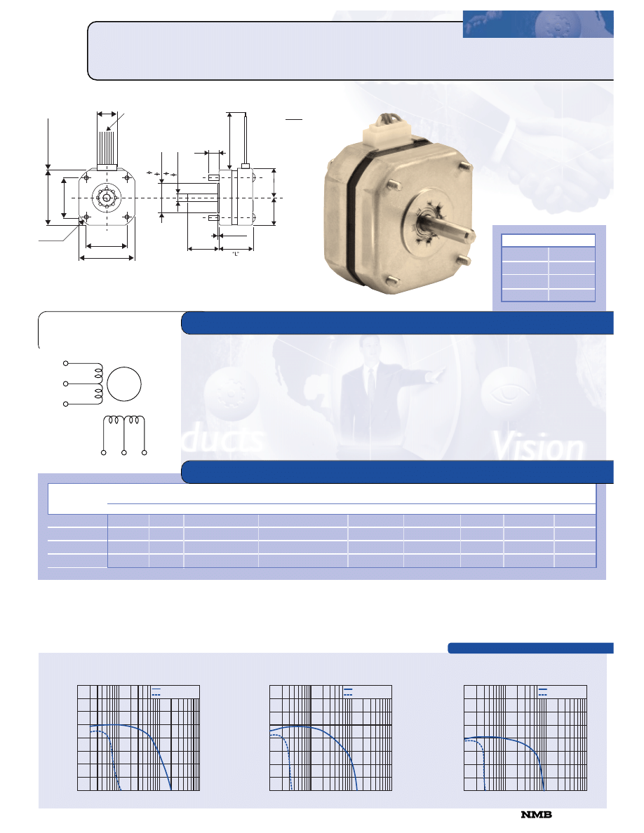
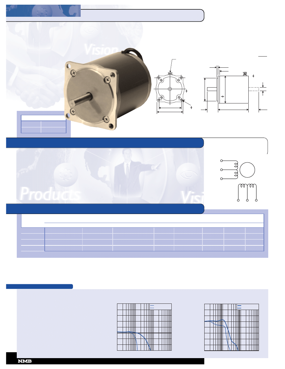
23LY-C 0.9
º
HYBRID
Step Angle ....................................................................... 0.9º
Step Angle Accuracy ..................................................... +/-5%
Temperature Rise.................................................. 80º C Max.
Ambient Temperature Range ........................... -20º to +50º C
Insulation Resistance......................... 100M
Ω
Min., 500 VDC
Dielectric Strength................................... 500 VAC for 1 min.
Radial Play.................................. 0.02 mm Max. (450 g-load)
End Play ..................................... 0.08 mm Max. (450 g-load)
Switching Sequence............................................ See page 31
Rated
Rated Current/
Winding Resistance/
Holding
Rotor
Detent
Model
Voltage
Phase
Phase
Torque
Inductance
Inertia
Torque
Weight
Number
V
A
Ω
g-cm
mH
g-cm
2
g-cm
g
23LY-C205
4.0
1.10
3.6
3,000
5.3
55.0
250
360
23LY-C201
5.5
0.78
7.1
3,000
8.3
55.0
250
360
23LY-C202
3.75
1.25
3.0
3,000
4.5
55.0
250
360
23LY-C301
3.0
1.70
1.8
4,000
4.5
110.0
300
450
23LY-C303
5.1
1.00
5.1
4,000
13.0
110.0
300
450
23LY-C305
6.0
0.85
7.1
4,000
18.0
110.0
300
450
23LY-C002
4.3
1.60
2.7
4,800
7.2
160.0
350
560
23LY-C001
8.5
0.85
10.0
4,800
30.0
160.0
350
560
MODEL SPECIFICATIONS
PULL OUT TORQUE
PULL IN TORQUE
(N
•
m
x
10
-4
)
3500
3000
2500
2000
1500
1000
500
0
100 1K 10K 100K
(PPS)
Model: 23LY-C202
Driver: Unipolar Chopper Dual • Supply Voltage: 24.0 (Volt)
Drive Current: 1.25 (A/WDG) • Load Inertia: 172.0 (g-cm
2
)
P/N
“L”
23LY-C2XX
1.61 (41.0)
23LY-C3XX
1.45 (49.5)
23LY-C0XX
2.22 (56.5)
LEAD WIRE UL 3266
AWG 22
11.8 (300) MIN
(5
6
.4
)
2
.2
2
(
6
.3
5
)
0
.0
0
0
-
0
.0
1
3
+
.2
5
.0
0
0
0
-
+
.0
0
0
5
(
3
8
.1
)
0
.0
5
-
+
1
.5
0
.0
0
2
-
+
(4
7
.1
4
)
1
.8
6
(47.14)
1.86
(1.59)
.063
(4.76)
.187
(20.64)
.81
(56.4)
2.22
4 – 0.20
(5.08)
“L”
(5
6
.4
)
2
.2
2
Unit:
inches
(mm)
16
CORPORATION
•
818-341-0820
PULL OUT TORQUE
PULL IN TORQUE
(N
•
m
x
10
-4
)
3500
3000
2500
2000
1500
1000
500
0
100 1K 10K 100K
(PPS)
PULL OUT TORQUE
PULL IN TORQUE
(N
•
m
x
10
-4
)
3500
3000
2500
2000
1500
1000
500
0
100 1K 10K 100K
(PPS)
Model: 23LY-C002
Driver: Unipolar Chopper Dual • Supply Voltage: 24.0 (Volt)
Drive Current: 1.60 (A/WDG) • Load Inertia: 147.0 (g-cm
2
)
Model: 23LY-C305
Driver: Unipolar Chopper Dual • Supply Voltage: 24.0 (Volt)
Drive Current: 0.80 (A/WDG) • Load Inertia: 166.0 (g-cm
2
)
TORQUE/SPEED CHARACTERISTICS
GENERAL SPECIFICATIONS
RED
BLACK
YELLOW
GREEN
WHITE
BLUE
TORQUE/SPEED CHARACTERISTICS
WINDING
DIAGRAM
2
2
3
3
L
LM
M--C
C 1
1..8
8
ºº
H
HY
YB
BR
RIID
D
23LM-C 1.8
º
HYBRID
Step Angle ....................................................................... 1.8º
Step Angle Accuracy ..................................................... +/-5%
Temperature Rise.................................................. 80º C Max.
Ambient Temperature Range ........................... -20º to +50º C
Insulation Resistance......................... 100M
Ω
Min., 500 VDC
Dielectric Strength................................... 500 VAC for 1 min.
Radial Play.................................. 0.02 mm Max. (450 g-load)
End Play ..................................... 0.08 mm Max. (450 g-load)
Switching Sequence............................................ See page 31
LEAD WIRE UL 1007
AWG 22
11.8 (300) MIN
.25
.0000
-
.0005
+
( 6.35
0.000
-
0.012
+
)
.43
(1
.75
(19.05)
1)
.81
(20.64)
.826
(21)
.20
(5)
1.86 (47.14)
2.22 (56.4)
0.20
4-
(5.08)
1.50 .002
( 38.1 0.05)
0.063 (1.59)
.187 (4.76)
“L”
Unit:
inches
(mm)
Rated
Rated Current/
Winding Resistance/
Holding
Rotor
Detent
Model
Voltage
Phase
Phase
Torque
Inductance
Inertia
Torque
Weight
Number
V
A
Ω
g-cm
mH
g-cm
2
g-cm
g
23LM-C250V
3.00
1.50
2.00
3,200
2.5
55.0
500
360
23LM-C213V
2.20
2.00
1.10
3,200
1.3
55.0
500
360
23LM-C343V
3.30
1.50
2.20
4,300
3.5
110.0
550
450
23LM-C355V
2.50
2.00
1.25
4,300
2.3
110.0
550
450
23LM-C047V
4.70
1.50
3.10
5,200
6.1
160.0
600
540
23LM-C055V
3.40
2.00
1.70
5,200
3.5
160.0
600
540
MODEL SPECIFICATIONS
RED
BLACK
YELLOW
BLUE
WHITE
ORANGE
PULL OUT TORQUE
PULL IN TORQUE
(N
•
m
x
10
-4
)
7000
6000
5000
4000
3000
2000
1000
0
100 1K 10K 100K
(PPS)
Model: 23LM-C343V
Driver: Unipolar Chopper Dual • Supply Voltage: 24.0 (Volt)
Drive Current: 1.50 (A/WDG) • Load Inertia: 161.0 (g-cm
2
)
PULL OUT TORQUE
PULL IN TORQUE
(N
•
m
x
10
-4
)
3500
3000
2500
2000
1500
1000
500
0
100 1K 10K 100K
(PPS)
Model: 23LM-C250V
Driver: Unipolar Chopper Dual • Supply Voltage: 24.0 (Volt)
Drive Current: 1.50 (A/WDG) • Load Inertia: 161.0 (g-cm
2
)
PULL OUT TORQUE
PULL IN TORQUE
(N
•
m
x
10
-4
)
7000
6000
5000
4000
3000
2000
1000
0
100 1K 10K 100K
(PPS)
Model: 23LM-C047V
Driver: Unipolar Chopper Dual • Supply Voltage: 24.0 (Volt)
Drive Current: 1.50 (A/WDG) • Load Inertia: 161.0 (g-cm
2
)
P/N
“L”
23LM-C2XX
1.61 (41.0)
23LM-C3XX
1.95 (49.5)
23LM-C0XX
2.22 (56.5)
818-341-0820
CORPORATION
GENERAL SPECIFICATIONS
WINDING
DIAGRAM
GENERAL SPECIFICATIONS
TORQUE/SPEED CHARACTERISTICS
2
2
3
3
L
LM
M--K
K 11..8
8
ºº
H
HY
YB
BR
RIID
D
23LM-K 1.8
º
HYBRID
Step Angle ....................................................................... 1.8º
Step Angle Accuracy ..................................................... +/-5%
Temperature Rise.................................................. 80º C Max.
Ambient Temperature Range ........................... -20º to +50º C
Insulation Resistance......................... 100M
½ Min., 500 VDC
Dielectric Strength................................... 500 VAC for 1 min.
Radial Play.................................. 0.02 mm Max. (450 g-load)
End Play ..................................... 0.08 mm Max. (450 g-load)
Switching Sequence............................................ See page 31
WG 22
11.8 (300) MIN
.25
.0000
-
.0005
+
( 6.35
0.000
-
0.012
+
)
.43
(11)
.81
(20.64)
.826
(21)
.20
(5)
1.86 (47.14)
2.22 (56.4)
0.20
4-
(5.08)
1.50 .002
( 38.1 0.05)
0.063 (1.59)
.187 (4.76)
“L”
A
LEAD WIRE UL 1007
Unit:
inches
(mm)
.75
(19.05)
Rated
Rated Current/
Winding Resistance/
Holding
Rotor
Detent
Model
Voltage
Phase
Phase
Torque
Inductance
Inertia
Torque
Weight
Number
V
A
½
g-cm
mH
g-cm
2
g-cm
g
MODEL SPECIFICATIONS
Microstep/
Low Noise Series
PULL OUT TORQUE
PULL IN TORQUE
(N
•
m
x
10
-4
)
7000
6000
5000
4000
3000
2000
1000
0
100 1K 10K 100K
(PPS)
Model: 23LM-K047V
Driver: Unipolar Chopper Dual • Supply Voltage: 24.0 (Volt)
Drive Current: 1.50 (A/WDG) • Load Inertia: 161.0 (g-cm
2
)
PULL OUT TORQUE
PULL IN TORQUE
(N
•
m
x
10
-4
)
3500
3000
2500
2000
1500
1000
500
0
100 1K 10K 100K
(PPS)
Model: 23LM-K343V
Driver: Unipolar Chopper Dual • Supply Voltage: 24.0 (Volt)
Drive Current: 1.50 (A/WDG) •Load Inertia: 161.0 (g-cm
2
)
PULL OUT TORQUE
PULL IN TORQUE
(N
•
m
x
10
-4
)
3500
3000
2500
2000
1500
1000
500
0
100 1K 10K 100K
(PPS)
Model: 23LM-K250V
Driver: Unipolar Chopper Dual • Supply Voltage: 24.0 (Volt)
Drive Current: 1.50 (A/WDG) • Load Inertia: 161.0 (g-cm
2
)
P/N
“L”
23LM-K2XX
1.61 (41.0)
23LM-K3XX
1.95 (49.5)
23LM-K0XX
2.22 (56.5)
CORPORATION
•
818-341-0820
18
23LM-K250V
3.00
1.50
2.00
2,400
3.0
55.0
180
360
23LM-K213V
2.20
2.00
1.10
2,400
1.6
55.0
180
360
23LM-K343V
3.30
1.50
2.20
3,400
3.9
110.0
230
450
23LM-K355V
2.50
2.00
1.25
3,400
2.6
110.0
230
450
23LM-K047V
4.70
1.50
3.10
4,000
6.5
160.0
260
540
23LM-K055V
3.40
2.00
1.70
4,000
3.7
160.0
260
540
RED
BLACK
YELLOW
BLUE
WHITE
ORANGE
TORQUE/SPEED CHARACTERISTICS
WINDING
DIAGRAM
GENERAL SPECIFICATIONS
2
2
3
3
K
KM
M--C
C 11..8
8
ºº
H
HY
YB
BR
RIID
D
23KM-C 1.8
º
HYBRID
Step Angle ....................................................................... 1.8º
Step Angle Accuracy ..................................................... +/-5%
Temperature Rise.................................................. 80º C Max.
Ambient Temperature Range ........................... -20º to +50º C
Insulation Resistance......................... 100M
½ Min., 500 VDC
Dielectric Strength................................... 500 VAC for 1 min.
Radial Play.................................. 0.02 mm Max. (450 g-load)
End Play ..................................... 0.08 mm Max. (450 g-load)
Switching Sequence............................................ See page 31
Rated
Rated Current/
Winding Resistance/
Holding
Rotor
Detent
Model
Voltage
Phase
Phase
Torque
Inductance
Inertia
Torque
Weight
Number
V
A
½
g-cm
mH
g-cm
2
g-cm
g
MODEL SPECIFICATIONS
RED
BLACK
YELLOW
BLUE
WHITE
ORANGE
High Torque
PULL OUT TORQUE
PULL IN TORQUE
(N
•
m
x
10
-4
)
14000
12000
10000
8000
6000
4000
2000
0
100 1K 10K 100K
(PPS)
Model: 23KM-C379V
Driver: Unipolar Chopper Dual • Supply Voltage: 24.0 (Volt)
Drive Current: 1.50 (A/WDG) • Load Inertia: 161.0 (g-cm
2
)
P/N
“L”
23KM-C2XX
1.65 (42)
23KM-C3XX
1.97 (50)
23KM-C0XX
2.13 (54)
23KM-C7XX
2.99 (76)
PULL OUT TORQUE
PULL IN TORQUE
(N
•
m
x
10
-4
)
14000
12000
10000
8000
6000
4000
2000
0
100 1K 10K 100K
(PPS)
Model: 23KM-C716V
Driver: Unipolar Chopper Dual • Supply Voltage: 24.0 (Volt)
Drive Current: 1.50 (A/WDG) • Load Inertia: 161.0 (g-cm
2
)
PULL OUT TORQUE
PULL IN TORQUE
(N
•
m
x
10
-4
)
7000
6000
5000
4000
3000
2000
1000
0
100 1K 10K 100K
(PPS)
Model: 23KM-C250V
Driver: Unipolar Chopper Dual • Supply Voltage: 24.0 (Volt)
Drive Current: 1.50 (A/WDG) • Load Inertia: 161.0 (g-cm
2
)
818-341-0820
CORPORATION
(
6
.3
5
)
0
.0
0
0
–
0
.0
1
3
.2
5
.0
0
0
0
–
+
.0
0
0
5
(5
6
.4
)
2
.2
2
1
.8
6
.2
6
(4
7
.1
4
)
(56.4)
2.22
1.86
(47.14)
.76
(19.4)
(20.64)
.81
.063
(1.59)
.187
(4.76)
4 – 0.20
(5.08)
(6
.5
)
.2
6
(6
.5
)
.2
0
(5
.0
)
+
(
3
8
.1
)
0
.0
5
–
+
1
.5
0
0
.0
0
2
.0
0
5
–
.22
(5.5)
“L”
Unit:
inches
(mm)
LEAD WIRE UL1007
AWG 22
11.8 (300) MIN
23KM-C250V
3.30
1.50
2.20
4,400
2.6
150.0
200
470
23KM-C379V
4.10
1.50
2.70
8,000
3.6
230.0
300
590
23KM-C032V
5.10
1.50
3.40
9,500
5.4
280.0
350
680
23KM-C716V
6.30
1.50
4.20
14,000
6.8
440.0
600
1,050
WINDING
DIAGRAM
TORQUE/SPEED CHARACTERISTICS
2
2
3
3
K
KM
M--K
K 11..8
8
ºº
H
HY
YB
BR
RIID
D
23KM-K 1.8
º
HYBRID
Step Angle ....................................................................... 1.8º
Step Angle Accuracy ..................................................... +/-5%
Temperature Rise.................................................. 80º C Max.
Ambient Temperature Range ........................... -20º to +50º C
Insulation Resistance......................... 100M
½ Min., 500 VDC
Dielectric Strength................................... 500 VAC for 1 min.
Radial Play.................................. 0.02 mm Max. (450 g-load)
End Play ..................................... 0.08 mm Max. (450 g-load)
Switching Sequence............................................ See page 31
Rated
Rated Current/
Winding Resistance/
Holding
Rotor
Detent
Model
Voltage
Phase
Phase
Torque
Inductance
Inertia
Torque
Weight
Number
V
A
½
g-cm
mH
g-cm
2
g-cm
g
High Torque/
Microstep
PULL OUT TORQUE
PULL IN TORQUE
(N
•
m
x
10
-4
)
14000
12000
10000
8000
6000
4000
2000
0
100 1K 10K 100K
(PPS)
Model: 23KM-K716V
Driver: Unipolar Chopper Dual • Supply Voltage: 24.0 (Volt)
Drive Current: 1.50 (A/WDG) • Load Inertia: 161.0 (g-cm
2
)
PULL OUT TORQUE
PULL IN TORQUE
(N
•
m
x
10
-4
)
14000
12000
10000
8000
6000
4000
2000
0
100 1K 10K 100K
(PPS)
Model: 23KM-K032V
Driver: Unipolar Chopper Dual • Supply Voltage: 24.0 (Volt)
Drive Current: 1.50 (A/WDG) • Load Inertia: 161.0 (g-cm
2
)
PULL OUT TORQUE
PULL IN TORQUE
(N
•
m
x
10
-4
)
7000
6000
5000
4000
3000
2000
1000
0
100 1K 10K 100K
(PPS)
Model: 23KM-K250V
Driver: Unipolar Chopper Dual • Supply Voltage: 24.0 (Volt)
Drive Current: 1.50 (A/WDG) • Load Inertia: 161.0 (g-cm
2
)
P/N
“L”
23KM-K2XX
1.65 (42)
23KM-K3XX
1.97 (50)
23KM-K0XX
2.13 (54)
23KM-K7XX
2.99 (76)
(
6
.3
5
)
0
.0
0
0
0
.0
1
2
.2
5
.0
0
0
0
–
+
–
+
.0
0
0
5
(5
6
.4
)
2
.2
2
1
.8
5
.2
6
(4
7
.1
4
)
(56.4)
2.22
1.85
(47.14)
.76
(19.4)
(20.64)
.81
.063
(1.59)
.187
(4.76)
(5.08)
4 – 0.20
(6
.5
)
.2
6
(6
.5
)
.2
0
(5
.0
)
+
(
3
8
.1
)
0
.0
5
–
+
1
.5
0
0
.0
0
2
.0
0
5
–
.22
(5.5)
“L”
Unit:
inche
(mm
LEAD WIRE UL1007
AWG 22
11.8 (300) MIN
CORPORATION
•
818-341-0820
20
GENERAL SPECIFICATIONS
RED
BLACK
YELLOW
BLUE
WHITE
ORANGE
23KM-K250V
3.30
1.50
2.20
3,700
3.1
150.0
200
470
23KM-K379V
4.10
1.50
2.70
5,600
4.2
230.0
300
590
23KM-K032V
5.10
1.50
3.40
7,400
6.4
280.0
350
680
23KM-K716V
6.30
1.50
4.20
12,000
8.0
440.0
600
1050
MODEL SPECIFICATIONS
23LQ-C202V
3.9
1.1
3.50
2,300
4.0
55.0
370
360
23LQ-C309V
6.75
1.0
6.75
3,100
8.6
110.0
380
450
23LQ-C055V
3.4
2.0
1.70
3,600
2.7
160.0
450
540
Note: All models available with rear shafts.
TORQUE/SPEED CHARACTERISTICS
WINDING
DIAGRAM
GENERAL SPECIFICATIONS
2
2
3
3
L
LQ
Q--C
C 5
5
ºº
H
HY
YB
BR
RIID
D
23LQ-C 5
º
HYBRID
Step Angle ......................................................................... 5º
Step Angle Accuracy ..................................................... +/-5%
Temperature Rise.................................................. 80º C Max.
Ambient Temperature Range ........................... -20º to +50º C
Insulation Resistance......................... 100M
½ Min., 500 VDC
Dielectric Strength................................... 500 VAC for 1 min.
Radial Play.................................. 0.02 mm Max. (450 g-load)
End Play ..................................... 0.08 mm Max. (450 g-load)
Switching Sequence............................................ See page 31
Rated
Rated Current/
Winding Resistance/
Holding
Rotor
Detent
Model
Voltage
Phase
Phase
Torque
Inductance
Inertia
Torque
Weight
Number
V
A
½
g-cm
mH
g-cm
2
g-cm
g
MODEL SPECIFICATIONS
RED
BLACK
YELLOW
BLUE
WHITE
ORANGE
PULL OUT TORQUE
PULL IN TORQUE
(N
•
m
x
10
-4
)
3500
3000
2500
2000
1500
1000
500
0
100 1K 10K 100K
(PPS)
Model: 23LQ-C309V
Driver: Unipolar Chopper Dual • Supply Voltage: 24.0 (Volt)
Drive Current: 1.00 (A/WDG) • Load Inertia: 161.0 (g-cm
2
)
Model: 23LQ-C202V
Driver: Unipolar Chopper Dual • Supply Voltage: 24.0 (Volt)
Drive Current: 1.10 (A/WDG) • Load Inertia: 161.0 (g-cm
2
)
PULL OUT TORQUE
PULL IN TORQUE
(N
•
m
x
10
-4
)
3500
3000
2500
2000
1500
1000
500
0
100 1K 10K 100K
(PPS)
P/N
“L”
23LQ-C0XX
2.22 (56.5)
23LQ-C2XX
1.61 (41.0)
23LQ-C3XX
1.95 (49.5)
.25
.0000
-
.0005
+
( 6.35
0.000
-
0.012
+
)
0.20
4-
LEAD WIRE UL 1007
AWG 22
11.8 (300) MIN
.43
(
11
)
.81
(20.64)
.826
(21)
.20
(5)
1.85 (47.14)
2.20 (56.4)
(5.08)
1.50 .002
( 38.1 0.05)
0.063 (1.59)
.187 (4.76)
“L”
Unit:
inches
(mm)
.75
(19.05)
PULL OUT TORQUE
PULL IN TORQUE
(N
•
m
x
10
-4
)
3500
3000
2500
2000
1500
1000
500
0
100 1K 10K 100K
(PPS)
Model: 23LQ-C055V
Driver: Unipolar Chopper Dual • Supply Voltage: 24.0 (Volt)
Drive Current: 2.00 (A/WDG) • Load Inertia: 161.0 (g-cm
2
)
818-341-0820
CORPORATION
TORQUE/SPEED CHARACTERISTICS
WINDING
DIAGRAM
GENERAL SPECIFICATIONS
3
3
4
4
P
PM
M--C
C 11..8
8
ºº
H
HY
YB
BR
RIID
D
34PM-C 1.8
º
HYBRID
Step Angle ....................................................................... 1.8º
Step Angle Accuracy ..................................................... +/-5%
Temperature Rise.................................................. 80º C Max.
Ambient Temperature Range ........................... -20º to +50º C
Insulation Resistance......................... 100M
½ Min., 500 VDC
Dielectric Strength................................... 500 VAC for 1 min.
Radial Play.................................. 0.02 mm Max. (450 g-load)
End Play ..................................... 0.08 mm Max. (450 g-load)
Switching Sequence............................................ See page 31
34PM-C101
3.00
4.00
0.75
20,000
3.50
1,100.0
1,300
2,400
34PM-C108
12.00
1.00
12.00
20,000
56.00
1,100.0
1,300
2,400
34PM-C007
5.50
1.25
4.40
12,000
14.50
560.0
900
1,400
34PM-C049
1.70
4.70
0.36
12,000
1.65
560.0
900
1,400
Note: All models available with rear shafts.
RED
BLACK
RED/WHITE
GREEN
WHITE
GREEN/WHITE
PULL OUT TORQUE
PULL IN TORQUE
(KG CM)
–
35
30
25
20
15
10
5
0
100 1K 10K 100K
(PPS)
PULL OUT TORQUE
PULL IN TORQUE
(N
•
m
x
10
-4
)
14000
12000
10000
8000
6000
4000
2000
0
100 1K 10K 100K
(PPS)
Model: 34PM-C101
Driver: Dual Chopper • Supply Voltage: 35.0 (Volt)
Drive Current: 2.50 (A/PH) • Load Inertia: 26.9 (g-cm
2
)
P/N
“L”
34PM-C1XX
3.69 (93.7)
34PM-C0XX
2.44 (61.9)
Unit:
inches
(mm)
LEAD WIRE UL 3266
AWG 22
11.8 (300) MIN
2.74 (69.6)
3.25 (82.6)
.217
4-
(5.5)
2.875 .002
(73.025 0.05)
+
–
+
–
1.19
(30.2)
3
.3
7
5
(
8
5
.7
)
.0625 (1.59)
.187 (4.76)
“L”
1.125
(28.62)
.375
.0000
-
.0005
+
(9.525
.000
-
.013
+
)
Model: 34PM-C007
Driver: Dual Chopper • Supply Voltage: 35.0 (Volt)
Drive Current: 1.25 (A/PH) • Load Inertia: 26.9 (g-cm
2
)
CORPORATION
•
818-341-0820
22
Rated
Rated Current/
Winding Resistance/
Holding
Rotor
Detent
Model
Voltage
Phase
Phase
Torque
Inductance
Inertia
Torque
Weight
Number
V
A
½
g-cm
mH
g-cm
2
g-cm
g
MODEL SPECIFICATIONS
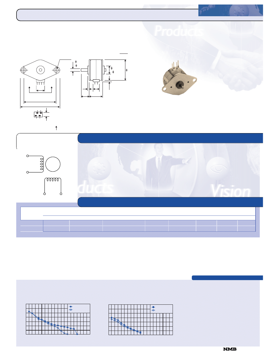
TORQUE/SPEED CHARACTERISTICS
WINDING
DIAGRAM
GENERAL SPECIFICATIONS
0
06
6
B
BJJ--H
H 118
8
ºº
P
PE
ER
RM
MA
AN
NE
EN
NT
T
M
MA
AG
G
N
NE
ET
T
06BJ-H 18
º
PERMANENT MAGNET
Step Angle ........................................................................ 18º
Step Angle Accuracy....................................................... +/-1º
Temperature Rise.................................................. 80º C Max.
Ambient Temperature Range ........................... -10º to +50º C
Insulation Resistance......................... 100M
½ Min., 500 VDC
Dielectric Strength................................... 500 VAC for 1 min.
Radial Play.................................. 0.05 mm Max. (100 g-load)
End Play ....................................... 0.3 mm Max. (100 g-load)
Switching Sequence............................................ See page 31
Rated
Rated Current/
Winding Resistance/
Holding
Rotor
Detent
Model
Voltage
Phase
Phase
Torque
Inductance
Inertia
Torque
Weight
Number
V
A
½
g-cm
mH
g-cm
2
g-cm
g
06BJ-H005
5.0
0.25
20.0
27
7.0
0.06
2.5
8
06BJ-H012
12.0
0.12
100.0
30
37.0
0.06
2.5
8
Note: This size is available in a bipolar winding only.
MODEL SPECIFICATIONS
A
––
A
—
B
B
PULL OUT TORQUE
PULL IN TORQUE
500
1000
1500
2000
0
5
10
15
20
25
30
35
0
FREQUENCY (pps)
R
U
N
N
IN
G
T
O
R
Q
U
E
(
g
–
c
m
)
Model: 06BJ-H012
Driver: Bipolar L/R Drive Dual Step
Supply Voltage: 12.0 (Volt)
Drive Current: 12.0 (A/PH)
PULL OUT TORQUE
PULL IN TORQUE
500
1000
1500
2000
0
5
10
15
20
25
30
35
0
FREQUENCY (pps)
R
U
N
N
IN
G
T
O
R
Q
U
E
(
g
–
c
m
)
Model: 06BJ-H005
Driver: Bipolar L/R Drive Dual Step
Supply Voltage: 5.0 (Volt)
Drive Current: 0.25 (A/PH)
Unit:
inches
(mm)
A
.20 (5)
+
–
.787 .008
+
–
(20 0.2)
A
.95 (24)
B
1
B
A
1
A
.05
(1.2)
AA
View
2 x .09 (2.3)
.059
.0000
-
.0004
+
( 1.5
.00
-
.01
+
)
0.59
(15)
.06
(1.5)
.04
(1)
(x2)
.177 .02
+
–
(4.5 0.5)
+
–
.16
(4)
.39
(9.8)
.197 +
–
.000
.002
( 5 +
–
0.00
0.05
)
818-341-0820
CORPORATION
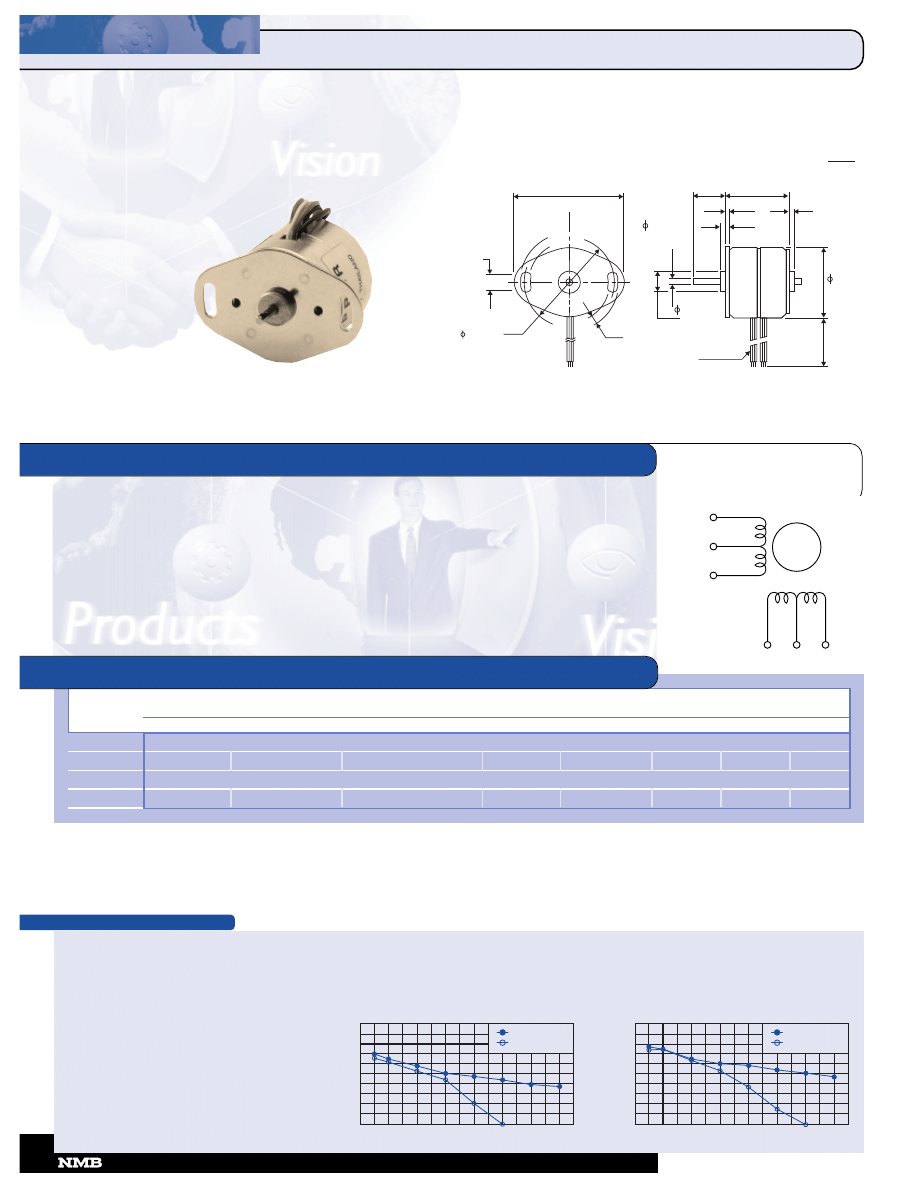
TORQUE/SPEED CHARACTERISTICS
WINDING
DIAGRAM
GENERAL SPECIFICATIONS
0
08
8B
BJJ--H
H 118
8
ºº
P
PE
ER
RM
MA
AN
NE
EN
NT
T
M
MA
AG
G
N
NE
ET
T
08BJ-H 18
º
PERMANENT MAGNET
Step Angle ........................................................................ 18º
Step Angle Accuracy....................................................... +/-1º
Temperature Rise.................................................. 80º C Max.
Ambient Temperature Range ........................... -10º to +50º C
Insulation Resistance......................... 100M
½ Min., 500 VDC
Dielectric Strength................................... 500 VAC for 1 min.
Radial Play.................................. 0.04 mm Max. (100 g-load)
End Play ....................................... 0.3 mm Max. (100 g-load)
Switching Sequence............................................ See page 31
Rated
Rated Current/
Winding Resistance/
Holding
Rotor
Detent
Model
Voltage
Phase
Phase
Torque
Inductance
Inertia
Torque
Weight
Number
V
A
½
g-cm
mH
g-cm
2
g-cm
g
Unipolar
08BJ-H007
3.8
0.19
20.0
40
7.0
0.2
10
30
Bipolar
08BJ-H040
2.1
0.35
6.0
40
5.0
0.2
10
30
MODEL SPECIFICATIONS
BROWN
BLACK
ORANGE
RED
BLACK
YELLOW
PULL OUT TORQUE
PULL IN TORQUE
500
1000
1500
0
10
20
30
40
50
0
FREQUENCY (pps)
R
U
N
N
IN
G
T
O
R
Q
U
E
(
g
–
c
m
)
Model: 08BJ-H040
Driver: Bipolar Chopper Dual
Supply Voltage: 24.0 (Volt)
Drive Current: 0.35 (A/PH)
PULL OUT TORQUE
PULL IN TORQUE
500
1000
1500
0
10
20
30
40
50
0
FREQUENCY (pps)
R
U
N
N
IN
G
T
O
R
Q
U
E
(
g
–
c
m
)
Model: 08BJ-H007
Driver: Unipolar Chopper Dual
Supply Voltage: 24.0 (Volt)
Drive Current: 0.19 (A/PH)
1.22 (31)
2 x .150
(3.8)
2 x .087 (2.2)
(25
)
.98
.059
.0000
-
+
(1.5
.00
-
.01
+
)
.0005
.272
-
+
.002
(6.9 0.5)
-
+
.06
(1.5)
.72 (18.3) MAX
.02
(0.6)
.06
(1.5)
.79
(20)
.236
.000
-
+
(6
.00
-
+
)
.002
.05
LEAD WIRE UL 1007
AWG 28
Unit:
inches
(mm)
.002
-
+
.05
-
+
11.8
(300) MIN
CORPORATION
•
818-341-0820
24
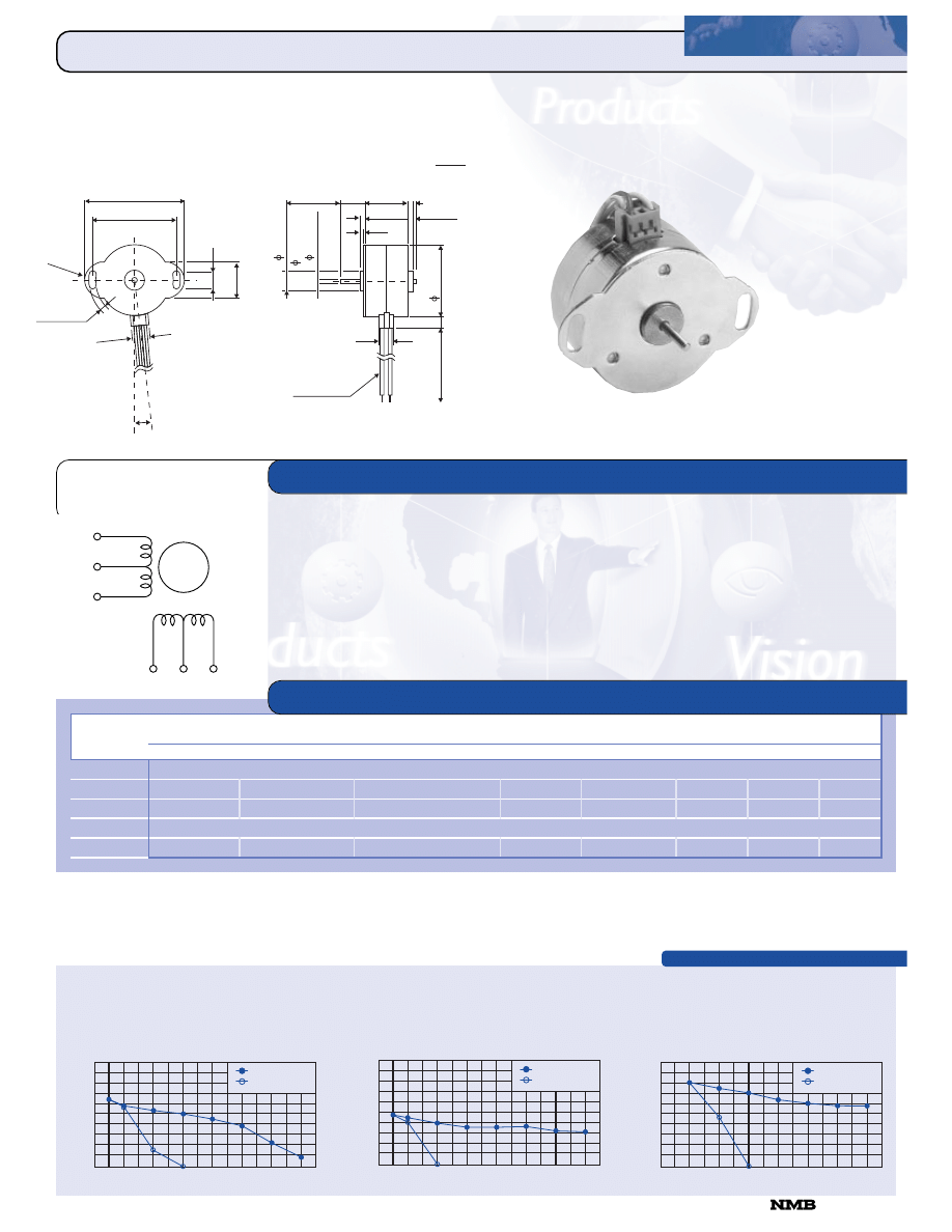
TORQUE/SPEED CHARACTERISTICS
WINDING
DIAGRAM
GENERAL SPECIFICATIONS
115
5
B
BA
A--H
H 115
5
ºº
P
PE
ER
RM
MA
AN
NE
EN
NT
T
M
MA
AG
G
N
NE
ET
T
15BA-H 15
º
PERMANENT MAGNET
Step Angle ........................................................................ 15º
Step Angle Accuracy....................................................... +/-1º
Temperature Rise.................................................. 80º C Max.
Ambient Temperature Range ........................... -10º to +50º C
Insulation Resistance......................... 100M
½ Min., 500 VDC
Dielectric Strength................................... 500 VAC for 1 min.
Radial Play.................................. 0.03 mm Max. (100 g-load)
End Play ....................................... 0.3 mm Max. (100 g-load)
Switching Sequence............................................ See page 31
Rated
Rated Current/
Winding Resistance/
Holding
Rotor
Detent
Model
Voltage
Phase
Phase
Torque
Inductance
Inertia
Torque
Weight
Number
V
A
½
g-cm
mH
g-cm
2
g-cm
g
Unipolar
15BA-H051P
8.0
0.23
35.0
165
18.0
4.0
40
100
15BA-H073P
4.0
0.40
10.0
155
5.0
4.0
40
100
Bipolar
15BA-H043P
2.0
0.80
2.5
220
3.4
4.0
40
100
MODEL SPECIFICATIONS
BROWN
BLACK
ORANGE
RED
BLACK
YELLOW
PULL OUT TORQUE
PULL IN TORQUE
500
1000
1500
0
50
100
150
200
250
0
FREQUENCY (pps)
R
U
N
N
IN
G
T
O
R
Q
U
E
(
g
–
c
m
)
Model: 15BA-H073P
Driver: Unipolar Dual
Supply Voltage: 24.0 (Volt)
Drive Current: 0.40 (A/PH)
PULL OUT TORQUE
PULL IN TORQUE
500
1000
1500
0
50
100
150
200
250
0
FREQUENCY (pps)
R
U
N
N
IN
G
T
O
R
Q
U
E
(
g
–
c
m
)
Model: 15BA-H051P
Driver: Unipolar Dual
Supply Voltage: 24.0 (Volt)
Drive Current: 0.23 (A/PH)
PULL OUT TORQUE
PULL IN TORQUE
500
1000
1500
0
50
100
150
200
250
0
FREQUENCY (pps)
R
U
N
N
IN
G
T
O
R
Q
U
E
(
g
–
c
m
)
Model: 15BA-H043P
Driver: Bipolar Dual
Supply Voltage: 24.0 (Volt)
Drive Current: 0.80 (A/PH)
1.97
-
+
.008
(42
-
+
0.1
)
1.65
-
+
.004
R.3
(R 7.5
)
.13
-
+
.008
2-(3.3
-
+
0.2
)
.40
(10)
7.5
°Ÿ
.3
5
(9
)
.7
1
(1
8
)
.3
9
4
-
+
.0
0
0
.0
0
2
1
0
.0
0
.0
0
-
+
0
.0
5
(
)
2
.0
0
.0
0
-
+
0
.0
1
.0
7
8
7
.0
0
0
0
-
+
.0
0
0
4
(
)
+
( 10
-
0.5
)
+
( 50
-
0.2
)
.394
-
+
.02
.867 (22) MAX
.17 (4.1) MAX
.10 (2.5)
.06
.03
(1.5)
(0.8)
.30
(7.5)
LEAD WIRE UL 1007
AWG 26
(5
.5
)
.2
1
7
1
.3
8
-
+
.0
2
0
.5
-
+
(
)
3
5
.0
Unit:
inches
(mm)
11.8
(300) MIN
818-341-0820
CORPORATION
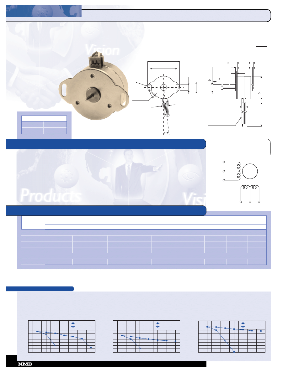
Unipolar
15BB-H051P
8.0
0.23
35.0
165
27.0
4.0
30
100
15BB-H073P
4.0
0.40
10.0
155
6.7
4.0
30
100
15BB-H170P
6.6
0.22
30.0
190
17.0
1.5
35
65
Bipolar
15BB-H043P
2.0
0.80
2.5
205
4.5
4.0
30
100
TORQUE/SPEED CHARACTERISTICS
WINDING
DIAGRAM
GENERAL SPECIFICATIONS
115
5
B
BB
B--H
H 7
7
..5
5
ºº
P
PE
ER
RM
MA
AN
NE
EN
NT
T
M
MA
AG
G
N
NE
ET
T
15BB-H 7.5
º
PERMANENT MAGNET
Step Angle ....................................................................... 7.5º
Step Angle Accuracy.................................................... +/-0.5º
Temperature Rise.................................................. 80º C Max.
Ambient Temperature Range ........................... -10º to +50º C
Insulation Resistance......................... 100M
½ Min., 500 VDC
Dielectric Strength................................... 500 VAC for 1 min.
Radial Play.................................. 0.03 mm Max. (100 g-load)
End Play ....................................... 0.3 mm Max. (100 g-load)
Switching Sequence............................................ See page 31
Rated
Rated Current/
Winding Resistance/
Holding
Rotor
Detent
Model
Voltage
Phase
Phase
Torque
Inductance
Inertia
Torque
Weight
Number
V
A
½
g-cm
mH
g-cm
2
g-cm
g
MODEL SPECIFICATIONS
BROWN
BLACK
ORANGE
RED
BLACK
YELLOW
PULL OUT TORQUE
PULL IN TORQUE
500
1000
1500
0
50
100
150
200
250
0
FREQUENCY (pps)
R
U
N
N
IN
G
T
O
R
Q
U
E
(
g
–
c
m
)
Model: 15BB-H043P
Driver: Bipolar Chopper Dual
Supply Voltage: 24.0 (Volt)
Drive Current: 0.80 (A/PH)
PULL OUT TORQUE
PULL IN TORQUE
500
1000
1500
0
50
100
150
200
250
0
FREQUENCY (pps)
R
U
N
N
IN
G
T
O
R
Q
U
E
(
g
–
c
m
)
Model: 15BB-H170P
Driver: Unipolar Chopper Dual
Supply Voltage: 24.0 (Volt)
Drive Current: 0.22 (A/PH)
PULL OUT TORQUE
PULL IN TORQUE
500
1000
1500
0
50
100
150
200
250
0
FREQUENCY (pps)
R
U
N
N
IN
G
T
O
R
Q
U
E
(
g
–
c
m
)
Model: 15BB-H051P
Driver: Unipolar Chopper Dual
Supply Voltage: 24.0 (Volt)
Drive Current: 0.23 (A/PH)
P/N
“L”
15BB-H0XX
.867 (20)
15BB-H1XX
.591 (15)
1.97
-
+
.008
(50
-
+
0.2
)
(50
-
+
0.2
)
1.65
-
+
.004
R.3
(R 7.5
)
.13
-
+
.008
2-(3.3
-
+
0.2
)
.40
(10)
7.5
°Ÿ
.3
5
(9
)
.7
1
(1
8
)
.3
9
4
-
+
.0
0
0
.0
0
2
1
0
.0
0
.0
0
-
+
0
.0
5
(
)
2
.0
0
.0
0
-
+
0
.0
1
.0
7
8
7
.0
0
0
0
-
+
.0
0
0
4
(
)
( 10
-
+
0.5
)
.394
-
+
.02
.17 (4.1) MAX
.10 (2.5)
.06
.03
(1.5)
(0.8)
.30
(7.5)
LEAD WIRE UL 1007
AWG 26
11.8 MIN
(300 MIN
(5
.5
)
.2
1
7
1
.3
8
-
+
.0
2
0
.5
-
+
(
)
3
5
.0
“L”
Unit:
inches
(mm)
CORPORATION
•
818-341-0820
26
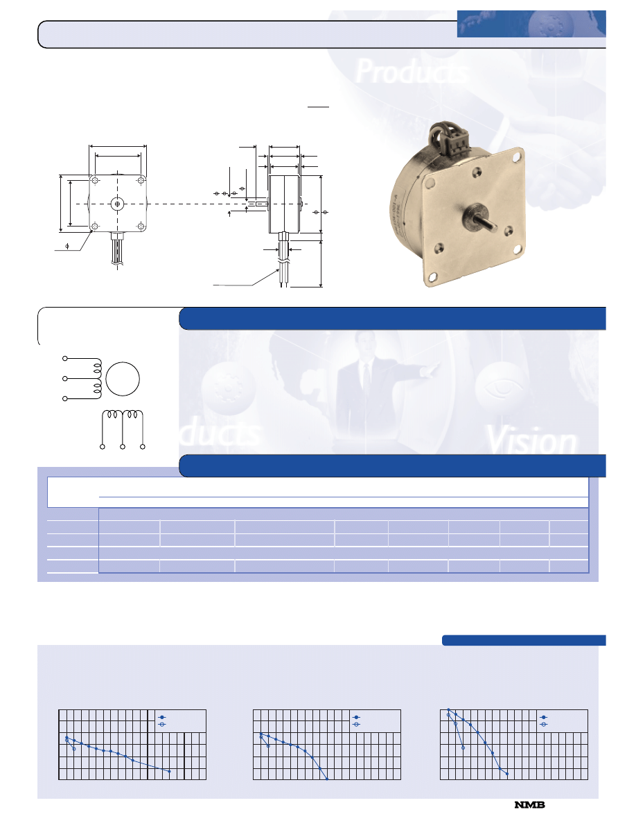
TORQUE/SPEED CHARACTERISTICS
WINDING
DIAGRAM
GENERAL SPECIFICATIONS
117
7
B
BB
B--H
H 7
7
..5
5
ºº
P
PE
ER
RM
MA
AN
NE
EN
NT
T
M
MA
AG
G
N
NE
ET
T
17BB-H 7.5
º
PERMANENT MAGNET
Step Angle ....................................................................... 7.5º
Step Angle Accuracy.................................................... +/-0.5º
Temperature Rise.................................................. 80º C Max.
Ambient Temperature Range ........................... -10º to +50º C
Insulation Resistance......................... 100M
½ Min., 500 VDC
Dielectric Strength................................... 500 VAC for 1 min.
Radial Play.................................. 0.03 mm Max. (220 g-load)
End Play ....................................... 0.3 mm Max. (220 g-load)
Switching Sequence............................................ See page 31
Rated
Rated Current/
Winding Resistance/
Holding
Rotor
Detent
Model
Voltage
Phase
Phase
Torque
Inductance
Inertia
Torque
Weight
Number
V
A
½
g-cm
mH
g-cm
2
g-cm
g
Unipolar
17BB-H262P
5.4
0.45
12.0
500
11.0
12.0
80
140
17BB-H267P
7.5
0.30
25.0
480
19.0
12.0
80
140
Bipolar
17BB-H240P
5.4
0.45
12.0
670
27.0
12.0
80
140
MODEL SPECIFICATIONS
BROWN
BLACK
ORANGE
RED
BLACK
YELLOW
PULL OUT TORQUE
PULL IN TORQUE
500
1000
1500
2000
0
200
400
600
0
FREQUENCY (pps)
R
U
N
N
IN
G
T
O
R
Q
U
E
(
g
–
c
m
)
Model: 17BB-H267P
Driver: Unipolar Chopper Dual
Supply Voltage: 24.0 (Volt)
Drive Current: 0.30 (A/PH)
PULL OUT TORQUE
PULL IN TORQUE
500
1000
1500
2000
0
200
400
600
0
FREQUENCY (pps)
R
U
N
N
IN
G
T
O
R
Q
U
E
(
g
–
c
m
)
Model: 17BB-H262P
Driver: Unipolar Chopper Dual
Supply Voltage: 24.0 (Volt)
Drive Current: 0.45 (A/PH)
PULL OUT TORQUE
PULL IN TORQUE
500
1000
1500
2000
0
200
400
600
0
FREQUENCY (pps)
R
U
N
N
IN
G
T
O
R
Q
U
E
(
g
–
c
m
)
Model: 17BB-H240P
Driver: Bipolar Chopper Dual
Supply Voltage: 24.0 (Volt)
Drive Current: 0.45 (A/PH)
.047
-
+
.008
.06
.03
(0.8)
.30
(7.5)
LEAD WIRE UL 1007
AWG 26
11.8
(300) MIN
.3
9
4
-
+
.0
0
0
.0
0
2
1
0
.0
0
.0
0
-
+
0
.0
5
(
)
0
.0
0
0
-
(
)
3
0
.0
1
2
.1
1
8
.0
0
0
0
-
+
+
.0
0
0
5
.031
(0.8)
.031
( 11.5
-
+
0.5
)
.453
-
+
.020
.06
.047
-
+
.008
(1.2
)
-
+
.2
(1.2
)
-
+
.2
.898 (22.8) MAX
(5
.5
)
.2
1
7
(
)
4
3
.2
1
.7
0
0
)
4 -
(
3.5
4-0.138
)
1.65
-
+
5.08
-
+
(
42
0.2
)
-
+
(
35
0.1
1.37
-
+
2.54
)
1
.6
5
-
+
5
.0
8
-
+
(
4
2
0
.2
)
-
+
(
3
5
0
.1
1
.3
7
-
+
2
.5
4
Unit:
inches
(mm)
818-341-0820
CORPORATION
NOTE: Also available with winged mounting brackets.
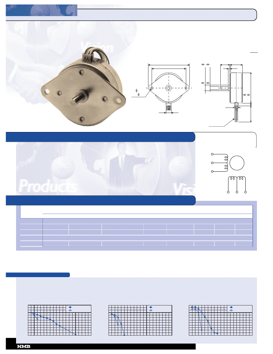
TORQUE/SPEED CHARACTERISTICS
WINDING
DIAGRAM
GENERAL SPECIFICATIONS
2
2
3
3
B
BB
B--H
H 7
7
..5
5
ºº
P
PE
ER
RM
MA
AN
NE
EN
NT
T
M
MA
AG
G
N
NE
ET
T
23BB-H 7.5
º
PERMANENT MAGNET
Step Angle ....................................................................... 7.5º
Step Angle Accuracy .................................................. +/-0.5%
Temperature Rise.................................................. 80º C Max.
Ambient Temperature Range ........................... -10º to +50º C
Insulation Resistance......................... 100M
½ Min., 500 VDC
Dielectric Strength................................... 500 VAC for 1 min.
Radial Play.................................. 0.03 mm Max. (220 g-load)
End Play ....................................... 0.3 mm Max. (220 g-load)
Switching Sequence............................................ See page 31
Rated
Rated Current/
Winding Resistance/
Holding
Rotor
Detent
Model
Voltage
Phase
Phase
Torque
Inductance
Inertia
Torque
Weight
Number
V
A
½
g-cm
mH
g-cm
2
g-cm
g
Unipolar
23BB-H251P
5.0
0.75
6.6
1,200
9.0
30.0
150
280
23BB-H252P
12.0
0.34
36.0
1,200
32.0
30.0
150
280
Bipolar
23BB-H246P
4.9
0.75
6.5
1,400
17.0
30.0
150
280
MODEL SPECIFICATIONS
BROWN
BLACK
ORANGE
RED
BLACK
YELLOW
PULL OUT TORQUE
PULL IN TORQUE
500
1000
1500
2000
0
400
200
600
800
1000
1200
0
FREQUENCY (pps)
R
U
N
N
IN
G
T
O
R
Q
U
E
(
g
–
c
m
)
Model: 23BB-H246P
Driver: Bipolar Chopper Dual
Supply Voltage: 24.0 (Volt)
Drive Current: 0.75 (A/PH)
PULL OUT TORQUE
PULL IN TORQUE
500
1000
1500
2000
0
400
200
600
800
1000
1200
0
FREQUENCY (pps)
R
U
N
N
IN
G
T
O
R
Q
U
E
(
g
–
c
m
)
Model: 23BB-H252P
Driver: Unipolar Chopper Dual
Supply Voltage: 24.0 (Volt)
Drive Current: 0.32 (A/PH)
PULL OUT TORQUE
PULL IN TORQUE
500
1000
1500
2000
0
400
200
600
800
1000
1200
0
FREQUENCY (pps)
R
U
N
N
IN
G
T
O
R
Q
U
E
(
g
–
c
m
)
Model: 23BB-H251P
Driver: Unipolar Chopper Dual
Supply Voltage: 24.0 (Volt)
Drive Current: 0.75 (A/PH)
LEAD WIRE UL 1007
AWG 26
2–
( 4.3)
.169
)
3.126 -
+
.008
-
+
(
79.4
0.2
)
2.622 -
+
.004
-
+
(
66.6
0.1
.40
(10)
0
.0
0
0
.0
2
)
(
1
1
.1
2
.4
3
8
.0
0
0
0
.0
0
0
8
0
.0
0
0
0
.0
1
2
(
)
6
.3
5
.2
5
.0
0
0
0
.0
0
0
5
)
-
0.5
(
+
20
1.0 (25.4) MAX
-
.0197
+
.787
(2.5)
(1.6)
.098
.063
(
)
5
7
.4
2
.2
6
-
.0
2
+
-
+
.0
5
(5
.5
)
.2
2
(7.5)
.30
11.8
(300) M
Unit:
inches
(mm)
-
+
-
+
-
+
-
+
CORPORATION
•
818-341-0820
28
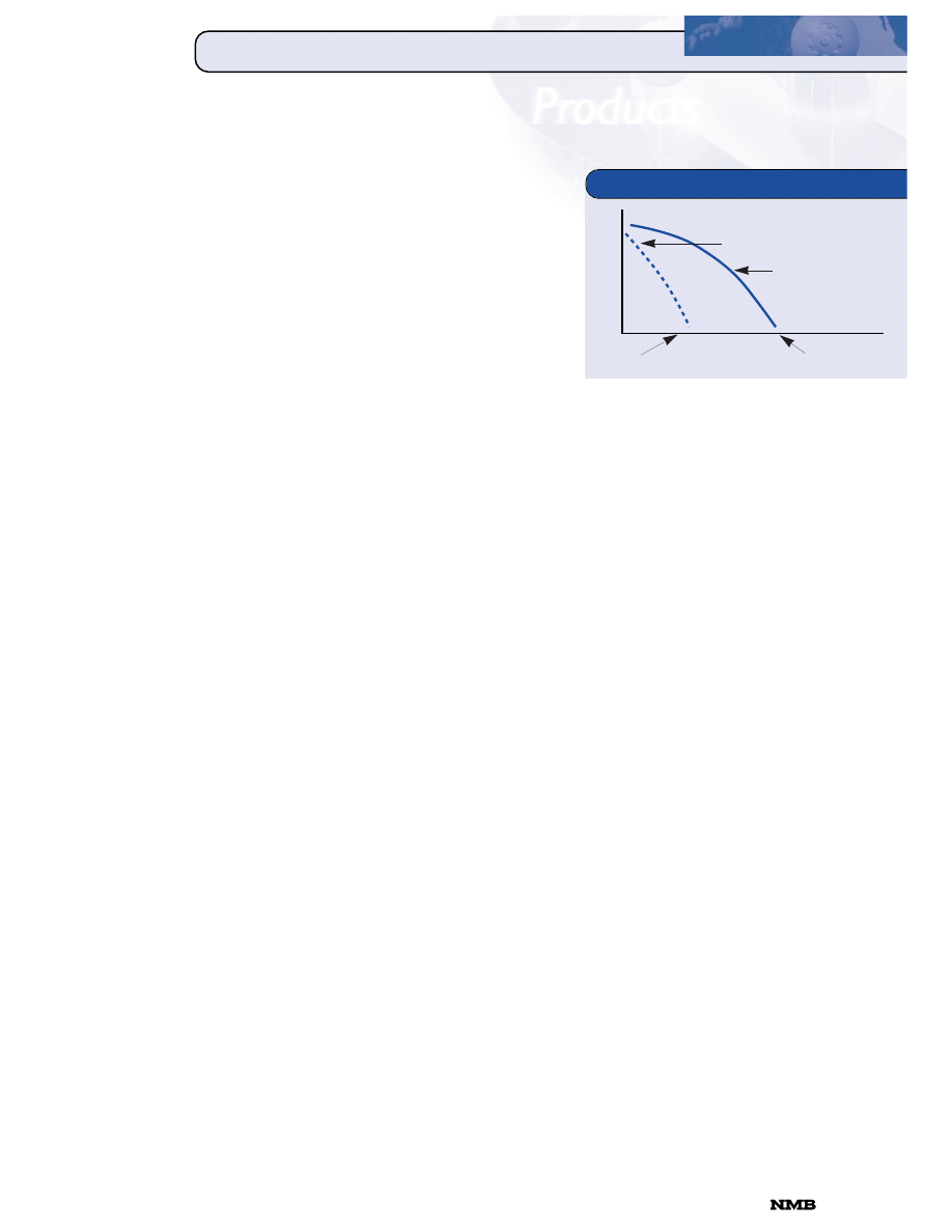
M
MO
OT
T
O
OR
R
T
T
E
ER
RM
MIIN
NO
OL
LO
OG
G
Y
Y
At a particular high
frequency the motor
can only generate
enough torque to keep
the rotor moving.
This is the
maximum
response rate at which
the available torque is
zero (refer to Figure 1).
To start rotation, some energy is used converting
the rotor’s inertia from a static to a dynamic state.
During this special condition, starting from zero
speed, the maximum torque developed is called
pull in torque. Pull in torque will decrease as you
increase frequency. At some point the torque
developed from starting will be zero. This is the
maximum start/stop frequency.
After reaching constant velocity (synchronism),
the motor can be accelerated or slewed up even
further to attain higher torque or higher speed.
The maximum torque developed from slewing up is
called pull out torque.
In this catalog, all torque and speed measurements
are made at the rated current. If the motor is run
at a current higher than the rated current, the
torque speed curve will shift up proportionately.
However, most of the increase is lost in heat. At a
particular high current, the coil temperature will
rise to the point at which the insulation is
threatened. The maximum temperature rise is the
maximum temperature increase the coil can
withstand without affecting its insulation.
A major advantage of step motors is that with one
or more phases left on, the rotor holds its
position. If the rotor is forced from this holding
position, it will attempt to move back. The maximum
restoring torque a motor develops is called holding
torque. It is the highest torque the motor can
develop. In this catalog, the holding torque is
measured at rated current with two phases on.
STEP MOTOR
CONSTRUCTION
The advantage of step motors is that they can
operate open loop, that is, they can stop at a
predictable angle, rotate clockwise, counterclock-
wise, and vary speed without feedback. Step motors
are electrically commutated, and need either a
unipolar or bipolar driver to effect rotation.
Hybrid step motors from page 7 to 22 have
electromagnetic poles, or phases, located radially
around a magnetized rotor. When a phase is
energized, it will pull the rotor magnetic pole into
alignment. When phases are pulsed in rotation,
called a switching sequence (refer to page 31) they
create a rotating magnetic stator field. The rotor
fields will continue to align themselves, thus causing
rotation. Applying potential to one pole is called
one pulse. One pulse will move the motor one step.
The amount of rotor movement in one pulse
is called the step angle. On many of the motors,
the step angle is 1.8 degrees. The error on each
step is generally quite small, usually +/-5% as
measured from a fitted centerline, and is referred
to as step angle accuracy. The step error does not
accumulate.
The permanent magnet step motors, from page 23
to 28, consist of bobbin wound coils and precision
stamping. This construction is easier to assemble,
and has a lower cost than hybrid motors.
Permanent magnet step motors typically have a
larger step angle and lower torque than hybrid
motors of the same size.
TORQUE
AND SPEED
Motor torque is the product of the motor’s gener-
ated force, multiplied by the radius from the shaft
center from where it is measured. The units are
either grams-centimeters (g-cm), milliNewton
meters (mNm) or ounce-inches (oz-in). Conversions
for these rates, and for moments of inertia, are on
page 31. At low pulse rates, the motor has a high
torque output, and at high speeds, low torque.
TORQUE SPEED GRAPH
TORQUE (g-cm)
Figure 1
PULSE RATE (pps)
Max. Start/Stop
Frequency
Max. Response Rate
MOTOR TERMINOLOGY
Pull In Torque
Pull Out Torque
818-341-0820
CORPORATION
M
MO
OT
T
O
OR
R
T
T
E
ER
RM
MIIN
NO
OL
LO
OG
G
Y
Y
MOTOR TERMINOLOGY
WINDINGS
Motors are wound to accept current in one direction,
a unipolar motor, or in both directions, a bipolar
motor. In general, a bipolar motor has more torque
than a unipolar motor, except at high speeds. The
switching sequences for unipolar and bipolar
motors are different, and can be found on page
31. Winding diagrams for unipolar motors can be
found on the data sheets.
To increase torque, motors can be run with two
phases on simultaneously. This drive mode is
called dual phase or two phase on. Motors can also
be run single phase. A combination of both is
called half step mode. Half step mode results in a
rotor movement of one half the step angle, for
example, from 1.8 degrees to 0.9 degrees. Further,
by partially turning phases on and off you can
continue to reduce the step angle. This drive mode
is referred to as microstepping.
MOTOR SELECTION
Motor selection usually begins with determining
the torque required. Since step motors run open
loop, you need to know beforehand what the
maximum torque required is. During any duty
cycle, the load torque varies. Usually, the highest
torque requirement is in accelerating the load
from at rest to a set speed. The following variables
must be known to determine the torque required
to accelerate a load:
Motor Speed (pps) accelerating from
Motor Speed (pps) accelerating to
Rotor Inertia (g-cm
2
)
Load Inertia (must be less than 10X rotor inertia)
Step Angle (degrees)
The acceleration component of the load, plus
frictional loads, can be calculated as follows:
T
a
=
aJ + T
f
Where:
T
a
= Torque required to accelerate (g-cm)
a = Angular acceleration (radians/sec
2
)
J = Total inertia (g-cm sec
2
)
T
f
= Friction torque (g-cm
2
)
Inertia will include both load inertia and rotor
inertia. Acceleration must be converted from
radians per second to steps per second.
Converting for these factors we get:
T
a
= (J
m
+ J
1
)
x
(f
2
-f
1
) (2
¸q)
Æt
x
360º
Where:
J
m
= Motor rotor inertia (g-cm sec
2
)
J
1
= Load inertia (g-cm sec
2
)
f
2
= Ending (high speed) frequency (pps)
f
1
= Starting frequency (pps)
Æt = Time for acceleration (sec)
DETERMINING TORQUE NEEDS
Figure 2
LOAD
MOTOR
continued
For example, assuming the assembly in Figure 2,
what is the required torque to accelerate the load
in .10 seconds from 0 to 1,000 pps?
For this example, we estimate the torque required
for the load only, and input the acceleration of
gravity into the inertia moment by dividing it by
980 cm/sec
2
. From this we get:
T
a
= 150 g-cm
2
x
(1000pps)2
¸
x
1.8º
980 cm/s
2
.1 sec
x
360º
= 52 g-cm
To accelerate the load we would need at least
52 g-cm of torque, plus about 25% more for
the motor rotor. An additional 50-100% is
recommended as a safety margin, in case of load
variance or worn parts. The total is about 130
g-cm at 1,000 pps. If a small step angle is
required, a 14PM on page 7 has ample torque.
J
1
= 150 g-cm
2
CORPORATION
•
818-341-0820
30
C
CO
ON
NV
VE
ER
RS
S
IIO
ON
N
T
T
A
AB
BL
LE
ES
S
CONVERSION TABLES
g-cm
1
1.388 x 10
-2
10
-3
8.679 x 10
-4
9.806 x 10
-5
7.233 x 10
-5
10
-5
oz-in
72.007
1
7.200 x 10
-2
6.25 x 10
-2
7.061 x 10
-3
5.208 x 10
-3
7.200 x 10
-4
Kg-cm
1000
13.877
1
.8679
9.806 x 10
-2
7.233 x 10
-2
10
-2
lb-in
1.152 x 10
3
16
1.152
1
.112
8.333 x 10
-2
1.152 x 10
-2
N-m
1.019 x 10
4
141.612
10.197
8.850
1
.737
.101
lb-ft
1.382 x 10
4
192
13.825
12
1.355
1
.138
Kg-m
10
5
1.388 x 10
3
100
86.796
9.806
7.233
1
ROTARY INERTIA CONVERSION TABLE
To convert from A to B, multiply by entry in table.
g-cm
2
1
5.46 x 10
-3
1.01 x 10
-3
10
-3
3.417 x 10
-4
1.41 x 10
-5
2.37 x 10
-6
1.01 x 10
-6
8.85 x 10
-7
7.37 x 10
-8
oz-in
2
182.9
1
.186
.182
.0625
2.59 x 10
-3
4.34 x 10
-4
1.86 x 10
-4
1.61 x 10
-4
1.34 x 10
-5
g-cm-s
2
980.6
5.36
1
.9806
.335
1.38 x 10
-2
2.32 x 10
-3
10
-3
8.67 x 10
-4
7.23 x 10
-5
Kg-cm
2
1000
5.46
1.019
1
.3417
1.41 x 10
-2
2.37 x 10
-3
1.019 x 10
-3
8.85 x 10
-4
7.37 x 10
-5
lb-in
2
2.92 x 10
3
16
2.984
2.926
1
4.14 x 10
-2
6.94 x 10
-3
2.98 x 10
-3
2.59 x 10
-3
2.15 x 10
-4
oz-in-s
2
7.06 x 10
4
386.08
72.0
70.615
24.13
1
.1675
7.20 x 10
-2
6.25 x 10
-2
5.20 x 10
-3
lb-ft
2
4.21 x 10
5
2304
429.71
421.40
144
5.967
1
.4297
.3729
3.10 x 10
-2
Kg-cm-s
2
9.8 x 10
5
5.36 x 10
3
1000
980.66
335.1
13.887
2.327
1
.8679
7.23 x 10
-2
lb-in-s
2
1.129 x 10
6
6.177 x 10
3
1.152 x 10
3
1.129 x 10
3
386.08
16
2.681
1.152
1
8.33 x 10
-2
lb-ft-s
2
or
1.355 x 10
7
7.41 x 10
4
1.38 x 10
4
1.35 x 10
4
4.63 x 10
3
192
32.17
13.825
12
1
slug-ft
2
TORQUE CONVERSION TABLE
To convert from A to B, multiply by entry in table.
SWITCHING SEQUENCE TABLES
For clockwise rotation facing the mounting side.
B
g-cm
oz-in
Kg-cm
lb-in
N-m
lb-ft
Kg-m
A
1
–
–
+
2
–
–
+
3
–
–
+
4
–
–
+
Dual Phase Excitation
Step
A
B
A
1
B
1
Common
1
+
+
–
–
2
–
+
+
–
3
–
–
+
+
4
+
–
–
+
Bipolar Dual Phase
Step
A
B
A
1
B
1
ORDERING INFORMATION AND WARRANTY
WARRANTY—NMB Corporation motors are warranted to be free of defects in materials and workmanship for
a period of one year from date of delivery.
APPLICATION ENGINEERING—For application engineering consultation, contact your local NMB Corporation
Sales Office to receive prompt assistance.
SPECIFICATIONS—NMB Corporation reserves the right to change specifications and prices without notice as
required to permit improvements in motor design.
INVENTORY—This catalog is a technical guide for the designer of products using stepping motors. Please
contact your local NMB Corporation Sales Office for information on the availability of specific stepping
motors and drive characteristics listed herein. Most stepping motors shown here were manufactured to
specific applications and thus are not available from inventory. NMB can modify any motor in this catalog
to meet your particular requirements.
818-341-0820
CORPORATION
B
g-cm
2
oz-in
2
g-cm-s
2
Kg-cm
2
lb-in
2
oz-in-s
2
lb-ft
2
Kg-cm-s
2
lb-in-s
2
lb-ft-s
2
A
or slug-ft
2

P E O P L E
P R O D U C T S
V I S I O N
A Minebea Group Company
Precision
Step Motors
P E O P L E
P R O D U C T S
V I S I O N
ISO 9002
QS 9000
ISO 9001
SMC 11/98
d in USA
P E O P L E
P R O D U C T S
V I S I O N
International Sales Offices
NMB Corporation Sales Offices
North America
Corporate Headquarters
9730 Independence Avenue, Chatsworth, CA 91311
Ph. 818-341-0820, Fax 818-709-0387
Western Regional Office
1735 Technology Drive, Suite 700, San Jose, CA 95110
Ph. 408-437-5636, Fax 408-437-5610
Western District Office
9730 Independence Avenue, Chatsworth, CA 91311
Ph. 818-341-0820, Fax 818-341-7316
Central Regional Office
50 East Commerce Drive, Suite A, Schaumburg, IL 60173
Ph. 847-843-3233, Fax 847-843-0955
Eastern Regional Office
4025 Steve Reynolds Boulevard, Suite 106, Norcross, GA 30093
Ph. 770-923-4477, Fax 770-923-8811
NMB Automotive
28700 Beck Road, Wixom, MI 48393
Ph. 248-926-0026, Fax 248-926-0025
S ˜ao Paulo, Brazil
Shanghai, China
Berkshire, England
Baillet en France, France
Langen, Germany
Kowloon, Hong Kong
Milan, Italy
Tokyo, Japan
Penang, Malaysia
Amsterdam, The Netherlands
Manila, Philippines
Singapore
Seoul, South Korea
Taipei, Taiwan
Bangkok, Thailand
Represented by:
A Minebea Group Company
9730 Independence Avenue
Chatsworth, CA 91311 U.S.A.
Tel: 818.341.0820
Fax: 818.709.0387
E-mail: info@nmbcorp.com
Web site: www.nmbcorp.com
ISO 14001
Wyszukiwarka
Podobne podstrony:
Minebea katalog silników krokowych
Katalog silników krokowych2
Opis silnikow krokowych id 3370 Nieznany
Kontroler silnika krokowego na porcie LPT3
Kontroler silnika krokowego na porcie LPT2
3 Silnik krokowy
badanie silnika krokowego, mechanika, BIEM- POMOCE, automatyka i sterowanie
Kontroler silnika krokowego na porcie LPT6
silniki krokowe
Instrukcja R4 Silnik krokowy
SILNIKI KROKOWE
Astra F Silnik krokowy w X16SZR
Najprostszy sterownik silników krokowych, ELEKTRONIKA
4 emulacja, silnik krokowy
3 Silnik krokowy
silniki krokowe
więcej podobnych podstron