
Exception and Interrupt Handling in ARM
Architectures and Design Methods for Embedded Systems
Summer Semester 2006
Author: Ahmed Fathy Mohammed Abdelrazek
Advisor: Dominik Lücke

Abstract
We discuss exceptions and interrupt handling techniques in ARM processors and see how
the ARM architecture works in this area to know how are these techniques suitable for
embedded systems to achieve the time constraints and safety requirements. Exception and
interrupt handling is a critical issue since it affect directly the speed of the system and how
fast does the system respond to external events and how does it deal with more than one
external event at the same time by assigning priorities to these events.
Table of contents
Abstract ...................................................................................................................................... 2
Table of contents ........................................................................................................................ 2
List of Figures ............................................................................................................................ 3
Abbreviations ............................................................................................................................. 3
1 Introduction ........................................................................................................................ 4
1.1
ARM modes of operation ...................................................................................... 4
1.2
ARM Register set................................................................................................... 5
................................................................................................................................................ 6
2 ARM
Exceptions ................................................................................................................ 6
2.1 Vector
Table .......................................................................................................... 7
2.2 Exception
priorities................................................................................................ 8
2.3
Link Register Offset............................................................................................... 8
2.4
Entering and exiting an exception handler............................................................. 9
3 Interrupts ............................................................................................................................ 9
3.1
How are interrupts assigned? ................................................................................. 9
3.2 Interrupt
Latency.................................................................................................. 10
3.3
IRQ and FIQ exceptions ...................................................................................... 10
3.4 Interrupt
stack ...................................................................................................... 10
4
Interrupt handling schemes .............................................................................................. 11
4.1 Non-nested
interrupt
handling ............................................................................. 11
4.1.1 Non-nested interrupt handling summery:.................................................................... 12
4.2
Nested interrupt handling..................................................................................... 12
4.2.1 Nested interrupt handling summery: ........................................................................... 13
4.3
Prioritized simple interrupt handling ................................................................... 13
4.3.1 Prioritized simple interrupt handling summery:.......................................................... 14
4.4 Other
schemes...................................................................................................... 15
5 Final
remarks.................................................................................................................... 16
Which interrupt handling scheme to use? ............................................................................ 16
References ................................................................................................................................ 17

List of Figures
Figure 1: Register Organization in ARM
[5]
............................................................................... 6
Figure 2 An exact vector table with the branching instruction
[5]
............................................... 7
Figure 3 Typical Memory Layouts........................................................................................... 11
Figure 4 Simple non nested interrupt handlers......................................................................... 12
Figure 5 Nested Interrupt Handling ......................................................................................... 13
Figure 6 Priority Interrupt Handler
[1]
....................................................................................... 14
Abbreviations
ISR
Interrupt Service Routine
SWI Software
Interrupt
IRQ Interrupt
Request
FIQ
Fast Interrupt Request
ARM
Advanced RISC Machines
RISC
Reduced Instruction Set Computers
SVC Supervisor
CPSR
Current Program Status Register
SPSR
Saved Program Status Register
LDR Load
Register
STR Store
Register
DMA
Direct Memory Access

1 Introduction
Exceptions are so important in embedded systems, without exception the development of
systems would be a very complex task. With exceptions we can detect bugs in the application,
errors in memory access and finally debug it by placing breakpoints and building the program
with debugging information.
Interrupts which are kinds of exceptions are essential in embedded systems. It enables the
system to deal with external events by receiving interrupt signals telling the CPU that there is
something to be done instead of the alternative way of doing the same operation by the
pooling mechanism which wastes the CPU time in looping forever checking some flags to
know that the event occurred.
Due to the fact that systems are going more complex day after day, we have nowadays
systems with more than one interrupt source. That is why an interrupt handling scheme is
needed to define how different cases will be handled. We may need priorities to be assigned
to different interrupts and in some other cases we may need nested handling capabilities.
We introduce the ARM processor itself to see its different modes of operation and then we
have an overview of the register set. This is because dealing with interrupts and exceptions
causes the ARM core to switch between these modes and copy some of the registers into other
registers to safe the core state before switching to the new mode. In the next chapter we
introduce exceptions and see how the ARM processor handles exceptions. In the third chapter
we define interrupts and discuss mechanisms of interrupt handling on ARM. In the forth
chapter we provide a set of standard interrupt handling schemes. And finally some remarks
regarding these schemes and which one is suitable to which application.
The main source of information provided in this paper is mainly the book “ARM System
Developer’s Guide”
[1]
.
1.1 ARM modes of operation
The ARM processor internally has 7 different modes of operation, they are as follows; User
mode: It is used for normal program execution state, FIQ mode: This mode is used for
interrupts requiring fast response and low latency like for example data transfer with DMA,
IRQ mode: This mode is used for general interrupt services, Supervisor mode: This mode is
used when operating system support is needed where it works as protected mode, Abort
mode: selected when data or instruction fetch is aborted, system mode: Operating system
privilege mode for users and undefined mode: When undefined instruction is fetched. The
following table summarizes the 7 modes:

Processor Mode
Description
User (usr)
Normal program execution mode
FIQ (fiq)
Fast data processing mode
IRQ (irq)
For general purpose interrupts
Supervisor (svc)
A protected mode for the operating system
Abort (abt)
When data or instruction fetch is aborted
Undefined (und)
For undefined instructions
System (sys)
Operating system privileged mode
1.2 ARM Register set
Register structure in ARM depends on the mode of operation. For example we have 16 (32-
bit) registers named from R0 to R15 in ARM mode (usr).
Registers R0 to R12 are general purpose registers, R13 is stack pointer (SP), R14 is
subroutine link register and R15 is program counter (PC).
R16 is the current program status register (CPSR) this register is shared between all modes
and it is used by the ARM core all the time and it plays a main role in the process of switching
between modes.
In other modes some of these 16 registers are visible and can be accessed and some others are
not visible and can’t be accessed. Also some registers are available with the same name but as
another physical register in memory which is called (banked), existence of such banked
registers decreases the effort needed when context switching is required since the new mode
has its own physical register space and no need to store the old mode’s register values.
So in ARM7 we have a total of 37 physical registers and the following figure shows the
ARM7 register set.
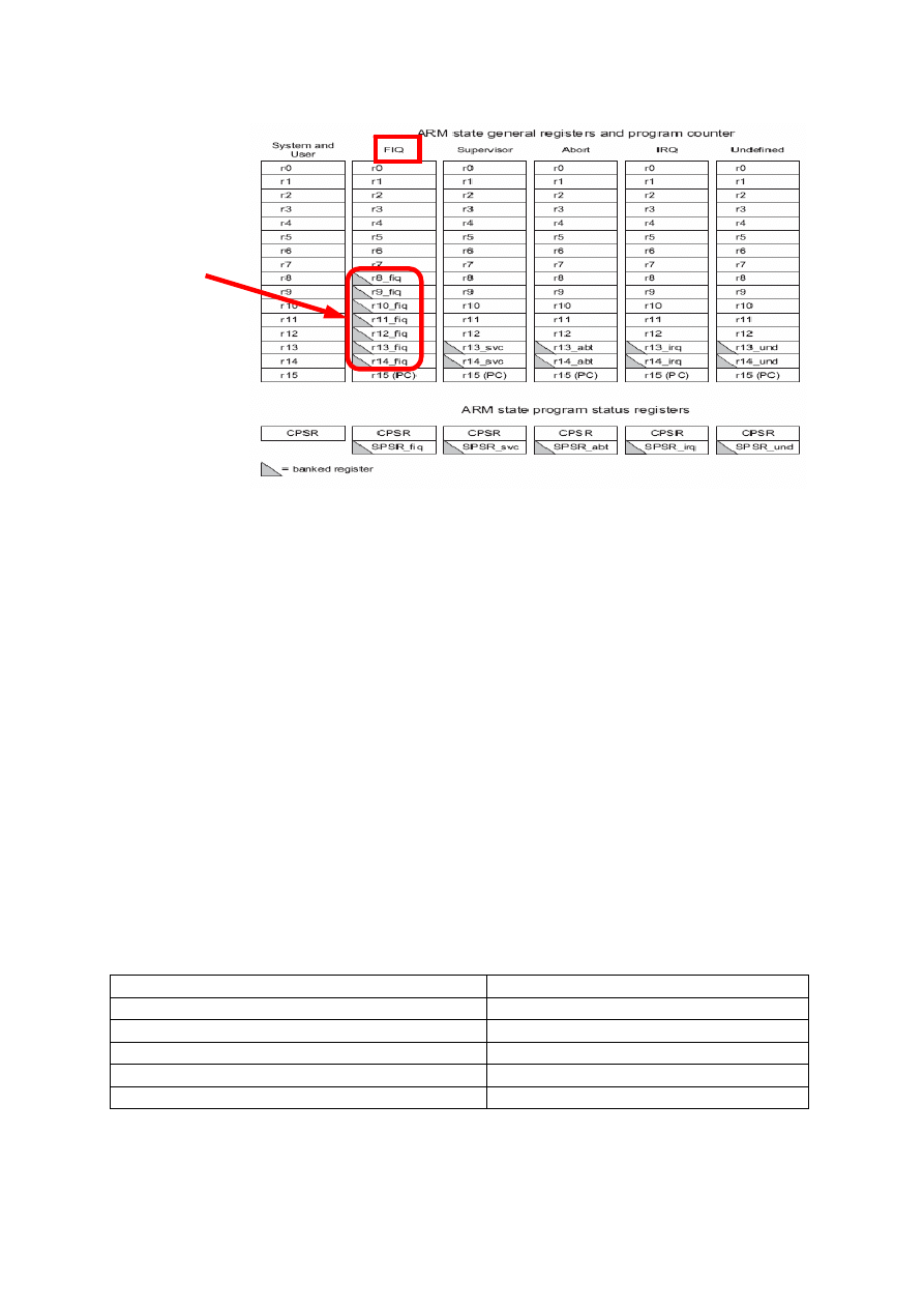
Figure 1: Register Organization in ARM
[5]
As we can see the banked registers are marked with the gray colour. We can notice that in the
FIQ mode there are more banked registers, this is to speed up the context switching since
there will be no need to store many registers when switching to the FIQ mode. We may need
only to store the values of registers r0 to r7 if the FIQ handler needs to use those registers, but
registers r8_fiq to r14_fiq are specific registers for the FIQ mode and can’t be accesses by any
other mode (they become invisible in other modes).
2 ARM
Exceptions
An exception is any condition that needs to halt normal execution of the instructions
[1]
. As an
example of exceptions the state of resetting ARM core, the failure of fetching instructions or
memory access, when an external interrupt is raised or when a software interrupt instruction is
executed. There is always software associated with each exception, this software is called
exception handler. Each of the ARM exceptions causes the ARM core to enter a certain mode
automatically also we can switch between different modes manually by modifying the CPSR
register. The following table summarises different exceptions and the associated mode of
operation on ARM processor.
Exception Mode
Fast Interrupt Request
FIQ
Interrupt Request
IRQ
SWI and RESET
SVC
Instruction fetch or memory access failure
ABT
Undefined Instruction
UND
More banked
registers, so
context switching
is faster
2.1 Vector Table
It is a table of instructions that the ARM core branches to when an exception is raised. These
instructions are places in a specific part in memory and its address is related to the exception
type. It always contains a branching instruction in one of the following forms:
• B <Add>
This instruction is used to make branching to the memory location with address “Add”
relative to the current location of the pc.
• LDR pc, [pc, #offset]
This instruction is used to load in the program counter register its old value + an offset
value equal to “offset”.
• LDR pc, [pc, #-0xff0]
This instruction is used only when an interrupt controller is available, to load a
specific ISR address from the vector table. The vector interrupt controller (VIC) is
placed at memory address 0xfffff000 this is the base address of the VIC. The ISR
address is always located at 0xfffff030.
• MOV pc, #immediate
Load in the program counter the value “immediate”.
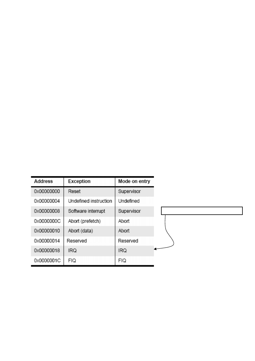
Figure 2 An exact vector table with the branching instruction
[5]
We can notice in the vector table that the FIQ exception handler is placed at the end of the
vector table, so no need for a branching instruction there; we can place the exception handler
directly there so handling begins faster by eliminating the time of branching.
At these addresses we find a jump
instruction like that:
ldr pc, [pc, #_IRQ_handler_offset]

2.2 Exception priorities
Since exceptions can occur simultaneously so we may have more than one exception raised at
the same time, the processor has to have a priority for each exception so it can decide which
of the currently raised exceptions is more important. The following table shows various
exceptions that occur on the ARM and their associated priorities.
Exception
Priority
I bit
F bit
Reset 1 1
1
Data Abort
2
1
-
FIQ 3 1
1
IRQ 4 1
-
Pre-fetch abort
5
1
-
SWI 6 1
-
Undefined instruction
6
1
-
We should notice the difference between prioritization of exceptions (when multiple
exceptions are valid at the same time), and the actual exception handler code. Exception
handlers are themselves liable to interruption by exceptions, and so we have the two bits
called F-bit and I-bit. The F-bit determines if exceptions can be ranked at all or not, when it is
1 so no other exceptions can be raised. And the I-bit is the same but for IRQ exceptions. The
Undefined Instruction and SWI cannot occur at the same time because they are both caused
by an instruction entering the execution stage of the ARM instruction pipeline, so are
mutually exclusive and thus they have the same priority.
2.3 Link Register Offset
The link register is used to return the PC (after handling the exception) to the appropriate
place in the interrupted task. It is modified based on the current PC value and the type of
exception occurred. For some cases it should point to the next instruction after the exception
handling is done and in some other cases it should return to one or 2 previous instructions to
repeat those instructions after the exception handling is done. For example, in the case of IRQ
exception, the link register is pointing initially to the last executed instruction + 8, so after the
exception is handled we should return to the old PC value + 4 (next instruction) which equals
to the old LR value – 4. Another example is the data abort exception, in this case when the
exception is handled, the PC should point to the same instruction again to retry accessing the
same memory location again.

2.4 Entering and exiting an exception handler
Here are the steps that the ARM processor does to handle an exception
[5]
:
• Preserve the address of the next instruction.
• Copy CPSR to the appropriate SPSR, which is one of the banked registers for each
mode of operation.
• Force the CPSR mode bits to a value depending on the raised exception.
• Force the PC to fetch the next instruction from the exception vector table.
• Now the handler is running in the mode associated with the raised exception.
• When handler is done, the CPSR is restored from the saved SPSR.
• PC is updated with the value of (LR – offset) and the offset value depends on the type
of the exception.
And when deciding to leave the exception handler, the following steps occurs:
• Move the Link Register LR (minus an offset) to the PC.
• Copy SPSR back to CPSR, this will automatically changes the mode back to the
previous one.
• Clear the interrupt disable flags (if they were set).
3 Interrupts
There are two types of interrupts available on ARM processor. The first type is the interrupt
caused by external events from hardware peripherals and the second type is the SWI
instruction.
The ARM core has only one FIQ pin, that is why an external interrupt controller is always
used so that the system can have more than one interrupt source which are prioritized with
this interrupt controller and then the FIQ interrupt is raised and the handler identifies which of
the external interrupts was raised and handle it.
3.1 How are interrupts assigned?
It is up to the system designer who can decide which hardware peripheral can produce which
interrupt request. By using an interrupt controller we can connect multiple external interrupts
to one of the ARM interrupt requests and distinguish between them.
There is a standard design for assigning interrupts adopted by system designers:
• SWIs are normally used to call privileged operating system routines.
• IRQs are normally assigned to general purpose interrupts like periodic timers.
• FIQ is reserved for one single interrupt source that requires fast response time, like
DMA or any time critical task that requires fast response.

3.2 Interrupt Latency
It is the interval of time between from an external interrupt signal being raised to the first
fetch of an instruction of the ISR of the raised interrupt signal.
System architects must balance between two things, first is to handle multiple interrupts
simultaneously, second is to minimize the interrupt latency.
Minimization of the interrupt latency is achieved by software handlers by two main methods,
the first one is to allow nested interrupt handling so the system can respond to new interrupts
during handling an older interrupt. This is achieved by enabling interrupts immediately after
the interrupt source has been serviced but before finishing the interrupt handling. The second
one is the possibility to give priorities to different interrupt sources; this is achieved by
programming the interrupt controller to ignore interrupts of the same or lower priority than
the interrupt being handled if there is one.
3.3 IRQ and FIQ exceptions
Both exceptions occur when a specific interrupt mask is cleared in the CPSR. The ARM
processor will continue executing the current instruction in the pipeline before handling the
interrupt. The processor hardware go through the following standard procedure:
• The processor changes to a specific mode depending on the received interrupt.
• The previous mode CPSR is saved in SPSR of the new mode.
• The PC is saved in the LR of the new mode.
• Interrupts are disabled, either IRQ or both IRQ and FIQ.
• The processor branches to a specific entry in the vector table.
Enabling/Disabling FIQ and IRQ exceptions is done on three steps; at first loading the
contents of CPSR then setting/clearing the mask bit required then copy the updated contents
back to the CPSR.
3.4 Interrupt stack
Exception handling uses stacks extensively because each exception has a specific mode of
operation, so switching between modes occurs and saving the previous mode data is required
before switching so that the core can switch back to its old state successfully. Each mode has
a dedicated register containing a stack pointer. The design of these stacks depends on some
factors like operating system requirements for stack design and target hardware physical
limits on size and position in memory. Most of ARM based systems has the stack designed
such that the top of it is located at high memory address. A good stack design tries to avoid
stack overflow because this causes instability in embedded systems.

In the following figure we have two memory layouts which show how the stack is placed in
memory:
Figure 3 Typical Memory Layouts
The first is the traditional stack layout. The second layout has the advantage that when
overflow occurs, the vector table remains untouched so the system has the chance to correct
itself.
4 Interrupt handling schemes
Here we introduce some interrupt handing schemes with some notes on each scheme about its
advantages and disadvantages.
4.1 Non-nested interrupt handling
This is the simplest interrupt handler. Interrupts are disabled until control is returned back to
the interrupted task. So only one interrupt can be served at a time and that is why this scheme
is not suitable for complex embedded systems which most probably have more than one
interrupt source and require concurrent handling. Figure 5 shows the steps taken to handle an
interrupt:
Initially interrupts are disabled, When IRQ exception is raised and the ARM processor
disables further IRQ exceptions from occurring. The mode is changed to the new mode
depending on the raised exception. The register CPSR is copied to the SPSR of the new
mode. Then the PC is set to the correct entry in the vector table and the instruction there will
direct the PC to the appropriate handler. Then the context of the current task is saved a subset
of the current mode non banked register. Then the interrupt handler executes some code to
identify the interrupt source and decide which ISR will be called. Then the appropriate ISR is
called. And finally the context of the interrupted task is restored, interrupts are enabled again
and the control is returned to the interrupted task.
Vector Table
Vector Table
User stack
Heap
Interrupt stack
Code
Code
Interrupt stack
Heap
User stack
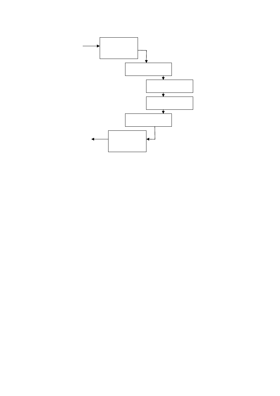
Figure 4 Simple non nested interrupt handlers
4.1.1 Non-nested interrupt handling summery:
• Handle and service individual interrupts sequentially.
• High interrupt latency.
• Relatively easy to implement and debug.
• Not suitable for complex embedded systems.
4.2 Nested interrupt handling
In this handling scheme handling more than one interrupt at a time is possible. This is
achieved by re-enabling interrupts before the handler has fully served the current interrupt.
This feature increases the complexity of the system but improves the latency. The scheme
should be designed carefully to protect the context saving and restoration from being
interrupted. The designer should balance between efficiency and safety by using defensive
coding style that assumes problems will occur.
The goal of nested handling is to respond to interrupts quickly and to execute periodic tasks
without any delays. Re-enabling interrupts requires switching out of the IRQ mode to user
mode to protect link register from being corrupted. Also performing context switch requires
emptying the IRQ stack because the handler will not perform switching if there is data on the
IRQ stack, so all registers saved on the IRQ stack have to be transferred to task stack. The
part of the task stack used in this process is called stack frame.
The main disadvantage of this interrupt handling scheme is that it doesn’t differ between
interrupts by priorities, so lower priority interrupt can block higher priority interrupts.
Disable
interrupts
Save context
Interrupt handler
ISR
Restore context
Enable
interrupts
Interrupt
Return to
task
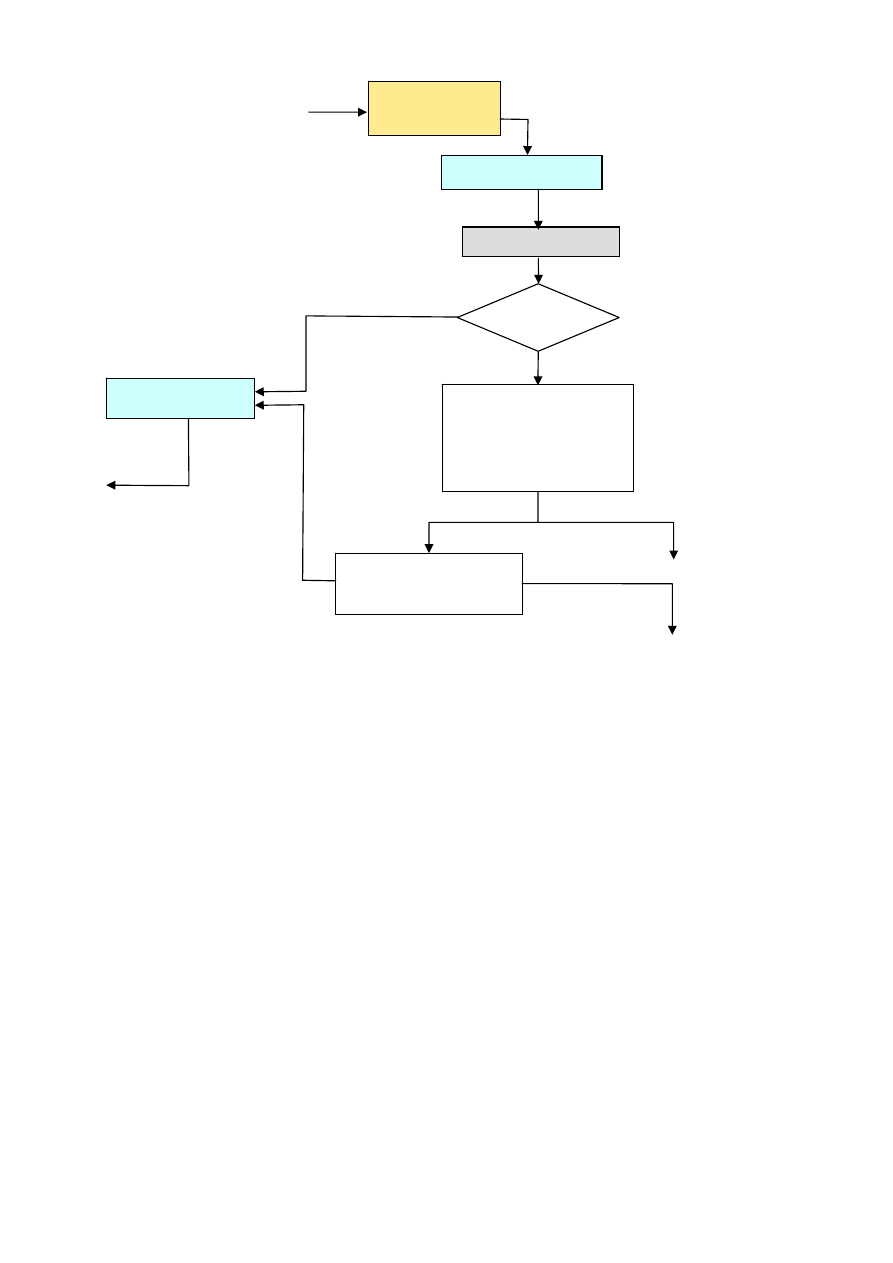
Figure 5 Nested Interrupt Handling
4.2.1 Nested interrupt handling summery:
• Handle multiple interrupts without a priority assignment.
• Medium or high interrupt latency.
• Enable interrupts before the servicing of an individual interrupt is complete.
• No prioritization, so low priority interrupts can block higher priority interrupts.
4.3 Prioritized simple interrupt handling
In this scheme the handler will associate a priority level with a particular interrupt source. A
higher priority interrupt will take precedence over a lower priority interrupt. Handling
prioritization can be done by means of software or hardware. In case of hardware
prioritization the handler is simpler to design because the interrupt controller will give the
interrupt signal of the highest priority interrupt requiring service. But on the other side the
system needs more initialization code at start-up since priority level tables have to be
constructed before the system being switched on.
Disable
interrupts
Save context
Interrupt handler
Restore context
Interrupt
Done?
Not yet complete
Prepare stack.
Switch mode.
Construct a frame.
Enable interrupts.
Complete serving
interrupt
Interrupt
Interrupt
Return to task
Serving is complete
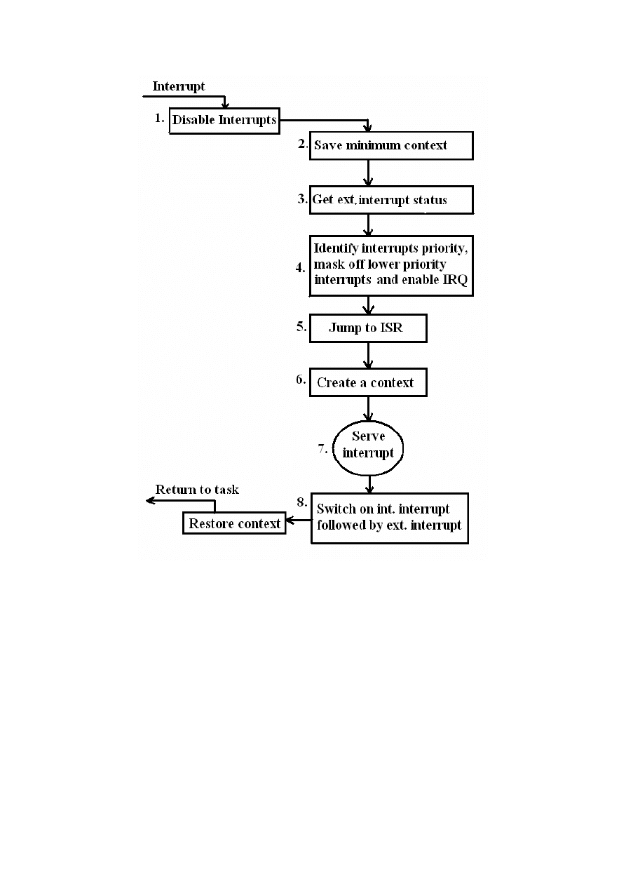
Figure 6 Priority Interrupt Handler
[1]
When an interrupt signal is raised, a fixed amount of comparisons with the available set of
priority levels is done, so the interrupt latency is deterministic but at the same point this could
be considered a disadvantage because both high and low priority interrupts take the same
amount of time.
4.3.1 Prioritized simple interrupt handling summery:
• Handle multiple interrupts with a priority assignment mechanism.
• Low interrupt latency.
• Deterministic interrupt latency.
• Time taken to get to a low priority ISR is the same as for high priority ISR.

4.4 Other schemes
There are some other schemes for handling interrupts, designers have to choose the suitable
one depending on the system being designed.
4.4.1 Re-entrant interrupt handler:
The basic difference between this scheme and the nested interrupt handling is that interrupts
are re-enabled early on the re-entrant interrupt handler which can reduce interrupt latency.
The interrupt of the source is disabled before re-enabling interrupts to protect the system from
getting infinite interrupt sequence. This is done by a using a mask in the interrupt controller.
By using this mask, prioritizing interrupts is possible but this handler is more complex.
4.4.2 Prioritized standard interrupt handler:
It is the alternative approach of prioritized simple interrupt handler; it has the advantage of
low interrupt latency for higher priority interrupts than the lower priority ones. But the
disadvantage now is that the interrupt latency in nondeterministic.
4.4.3 Prioritized grouped interrupt handler:
This handler is designed to handle large amount of interrupts by grouping interrupts together
and forming a subset which can have a priority level. This way of grouping reduces the
complexity of the handler since it doesn’t scan through every interrupt to determine the
priority. If the prioritized grouped interrupt handler is well designed, it will improve the
overall system response times dramatically, on the other hand if it is badly designed such that
interrupts are not well grouped, then some important interrupts will be dealt as low priority
interrupts and vice versa. The most complex and possibly critical part of such scheme is the
decision on which interrupts should be grouped together in one subset.

5 Final
remarks
Which interrupt handling scheme to use?
We can’t decide on one interrupt handling scheme to be used as a standard in all systems, it
depends on the nature of the system and how many interrupts are there, how complex is the
system and so on. For example; when our system has only periodic tasks then no need for
prioritized handling scheme, since all of our tasks have equal importance. And when our
system has a hardware interrupt from an external source that has hard real time determinism
and must be processed quickly, using prioritized schemes is better. Another point is the
number of interrupt sources, when we have large amount of interrupts, using grouped priority
handling scheme is a good choice.

References
[1] A.N. Sloss, D.Symes, C. Wright: ARM System Developer’s Guide, Publisher: Morgan
Kaufmann, March 25, 2004.
[2] Steve Furber: ARM System-On-Chip Architecture, 2
nd
Edition, Publisher: Addison-
Wesley, August 25, 2000.
[3] David Seal: ARM Architecture Reference Manual, 2
nd
Edition, Publisher: Addison-
Wesley, December 27, 2000.
[4]
ARM710T Datasheet,
Publisher: ARM, August 1998, retrieved from
http://www.arm.com/documentation/ARMProcessor_Cores/index.html
.
[5] ARM Technical Reference Manual, Publisher: ARM, March 2006, retrieved from
http://www.arm.com/documentation/ARMProcessor_Cores/index.html
.
Wyszukiwarka
Podobne podstrony:
report ICT 3 juin 08
PBO G 08 F05 Report of management review
PBO G 08 F03 Follow up report of management review
FP w 08
08 Elektrownie jądrowe obiegi
archkomp 08
02a URAZY CZASZKOWO MÓZGOWE OGÓLNIE 2008 11 08
ankieta 07 08
08 Kości cz Iid 7262 ppt
08 Stany nieustalone w obwodach RLCid 7512 ppt
2009 04 08 POZ 06id 26791 ppt
08 BIOCHEMIA mechanizmy adaptac mikroor ANG 2id 7389 ppt
depresja 08 09
W15 08 II
Szkol Ogólne 08 1pomoc
więcej podobnych podstron