
3
. INSPECTION/ADJUSTMENT
3-0
ZX /SCOUT 50
3
__________________________________________________________________________________
__________________________________________________________________________________
__________________________________________________________________________________
__________________________________________________________________________________
__________________________________________________________________________________
INSPECTION/ADJUSTMENT
__________________________________________________________________________________
INSPECTION AND MAINTENANCE SCHEDULE..................... 3- 1
BRAKE SYSTEM ..................................................................... 3- 4
MOVING DEVICE.................................................................... 3- 5
DAMPING DEVICE.................................................................. 3- 6
POWER DRIVE SYSTEM ......................................................... 3- 6
ELECTRICAL EQUIPMENT..................................................... 3- 7
ENGINE................................................................................... 3- 8
OTHERS .................................................................................. 3- 11
3
3
. INSPECTION/ADJUSTMENT
3-1
ZX /SCOUT 50
ZX /SCOUT 50
INSPECTION AND MAINTENANCE SCHEDULE
(Note) 1.
means time for inspection.
2.
means regular replacement for the specified parts.
This inspection and maintenance schedule is based upon average riding conditions.
Machines subjected to serve use, or ridden in unusually dusty areas, require more frequent
servicing.
Frequency
Inspection & Maintenance Item
Preride
1st
month
Every 6
months
Every 12
months
Judgment Standards Remarks
Check for looseness
and vertical play
Steering
handlebar
Operating performance
Right/left turning angle
Suspension
Damage
Check for front fork
pivot installation
Check
steering
stem
Front
fork
Check front fork pivot
for looseness and
abnormal noise
Check
steering
stem
Front/rear brake lever
free play
Free play:
10
20mm
Brake lever operation
Brake
Lever
Brake performance
Lever/
Cable
Looseness, abnormal
noise and damage
Brake
System
Drum-to-lining
clearance
Brake shoe and lining
wear
Indicator
type
Brake
drum/
shoe
Brake drum wear and
damage
Standard:
Front: 110 mm
Rear : 110 mm
Service Limits:
Front: 111 mm
Rear : 111 mm
Moving
Device
Tire
Tire pressure
Front
Rear
1
rider
1.50
kg/cm_
1.75
kg/cm_
Tire
Size
120/70-
12
120/70-
12

3
. INSPECTION/ADJUSTMENT
3-2
ZX /SCOUT 50
Frequency
Inspection & Maintenance Item
Preride
1st
month
Every 6
months
Every 12
months
Judgment Standards Remarks
Tire crack and damage
Tire groove and
abnormal wear
Groove Depth:
Front: 0.8mm
Rear : 0.8mm
Imbedded objects,
gravel, etc.
Moving
Device
Motor-
cycle
Axle nut looseness
Torque Values:
Front axle nut
5.0
7.0kg-m
Rear axle nut
11.0
13.0kg-m
Axle nut
torque
Check wheel rim, rim
edge and spoke plate
for damage
Rim runout at rim end:
Front: Axial
2.0mm
Radial 2.0mm
Rear:
Axial
2.0mm
Radial 2.0mm
Check front wheel
bear-ing for excessive
play and abnormal
noise
Check front wheel
bear-ing for excessive
play and abnormal
noise
Frame
Spring
Damage
Shock
spring
free
length
Suspen-
sion arm
Connecting parts
loose-ness and arm
damage
Shock
Oil leakage and damage
Damping
Device
absorber Assembly parts loose-
ness abnormal noise
Power
Clutch
Operation
Drive
System
Transmis
-sion case Oil leakage and oil
level
Oil level:
Oil check bolt hole
at lower hole edge
Rear wheel
transmis-
sion case
Ignition
device
Spark plug condition
Plug gap:
0.6
0.7mm
Electrical
Equipment
Battery
Terminal connection
Wires
Loose connection and
damage
3
. INSPECTION/ADJUSTMENT
3-3
ZX /SCOUT 50
ZX /SCOUT 50
Frequency
Inspection & Maintenance Item
Preride
1st
month
Every 6
months
Every 12
months
Judgment Standards Remarks
Performance and abnormal
noise
Body
Conditions at low and high
speeds
Exhaust smoke
Air cleaner
Oil quality and quantity
r Oil level indicator
Indicator light comes
on when oil is
insufficient
Engine
Oil leakage
Oil level
Lubrica-
tion
system
Check oil filter for clogging
Fuel leakage
Carburetor, throttle valve
and auto bystarter
Check fuel filter for
clogging
Fuel level
Fuel
System
Fuel tube replacement
Every 4 years
Operation
Lights
&
Winker
Winking action, dirt and
damage
Buzzer &
Steering Lock
Operation
R
earview
M
irror
& Reflector
Rearview mirror position
Rearview
Mirror
Reflector &
License Plate
Dirt and damage
Counter
Operation
Exhaust
Joint looseness and damage
Muffler
Exhaust muffler
performance
Body & Frame
Looseness and damage
Abnormal
Conditions
Happened Last
Time
Check if the abnormal
conditions occur again
Lubrication points
Others
Remove carbon deposits on
combustion chamber,
breather hole and exhaust
muffler
3
. INSPECTION/ADJUSTMENT
3-4
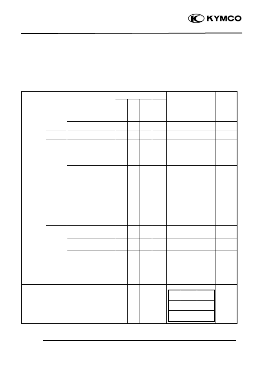
BRAKE DRUM/SHOE
Brake Shoe Wear
Replace the brake shoes if the arrow on the
brake arm aligns with reference mark“
”
on the brake panel when the brake is fully
applied.
Brake Drum Wear/Damage
Check the brake drum appearance for
damage. Check if the brake lining wear is
within the specified service limit. Check
the brake operation for abnormal noise and
brake drum inside for wear or damage.
BRAKE DISK/LINING
Brake Disk Surface and Brake Pad
Wear
Check the brake disk surface for scratch.
Check if the brake pad wear is within the
specified service limit.
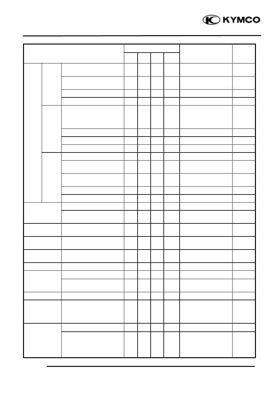
Brake Disk Runout Inspection
Jack the motorcycle wheels off the ground
and check if the brake disk runout is within
the specified service limit.
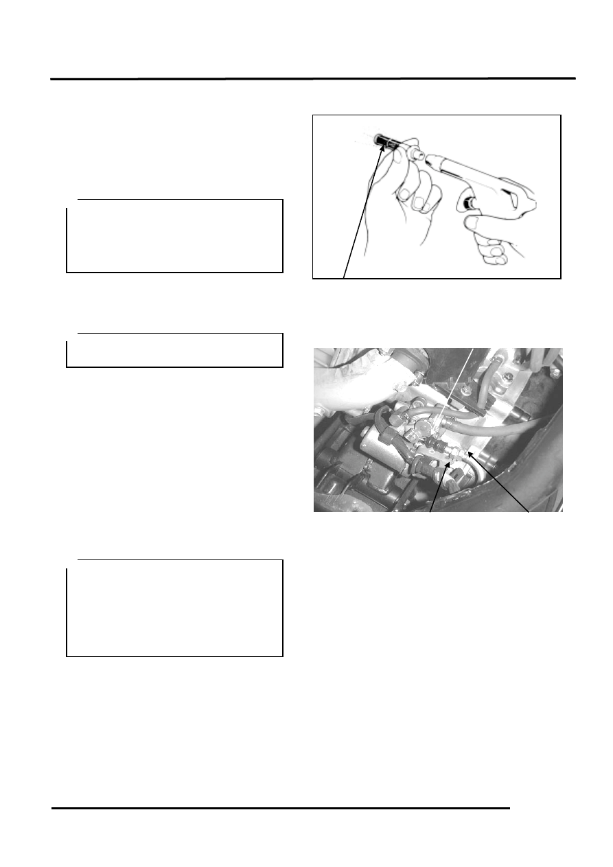
BRAKE FLUID LEVEL INSPECTION
Brake Master Cylinder Fluid Level
Inspection
Turn the steering handlebar upright and
check if the front brake fluid level is within
the specified limits through the front brake
master cylinder check hole.
“
” Marks <Rear>
Adjusting Nuts
Brake Disk
Brake Lining Service
Limit Mark
Brake Master Cylinder
<Front>
3
. LUBRICATION SYSTEM
3-5
MOVING DEVICE
TIRES
Tire Pressure
Check the tire pressure.
Tire Pressure (one rider)
Front: 1.50 kg/cm_
Rear: 1.75 kg/cm_
Tire Size:
Front: 120/70-12
Rear: 120/70-12
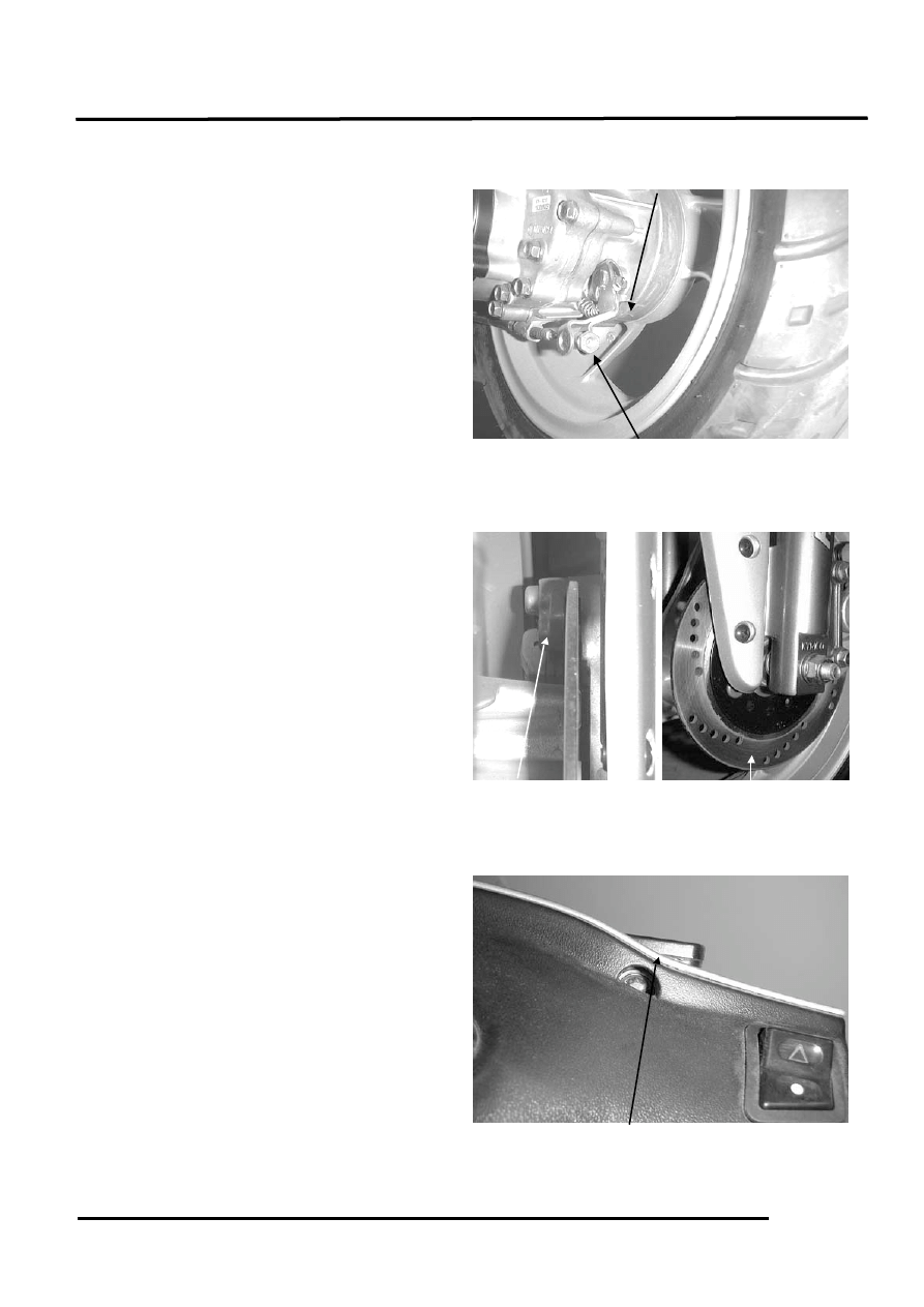
Axle Nut/Axle Shaft
Looseness
Check the front and rear axle nuts for
looseness.
If the axle nuts are loose, tighten them to
the specified torques.
Torques:
Front: 5.0
7.0kg-m
Rear: 11.0
13.0kg-m
Wheel Rim/Spoke Plate
Damage
Check the wheel rim and spoke plate for
wear or damage and measure the rim runout.
Axle Nut
Tire pressure should be checked when
tires are cold.
Axle Nut
Rear Wheel
3
. INSPECTION/ADJUSTMENT
3-6
DAMPING DEVICE
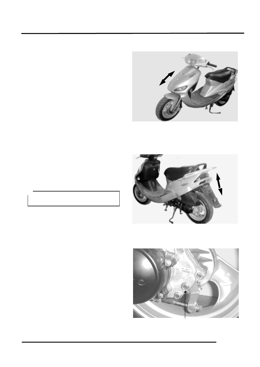
SHOCK ABSORBERS
Oil Leak/Damage
Fully apply the front brake and check the
action of the front shock absorber by
compressing it several times.
Check the entire shock absorber assembly
for looseness or damage.
Check the action of the rear shock absorber
by compressing it several times.
Check the entire shock absorber assembly
for looseness or damage.
POWER DRIVE SYSTEM
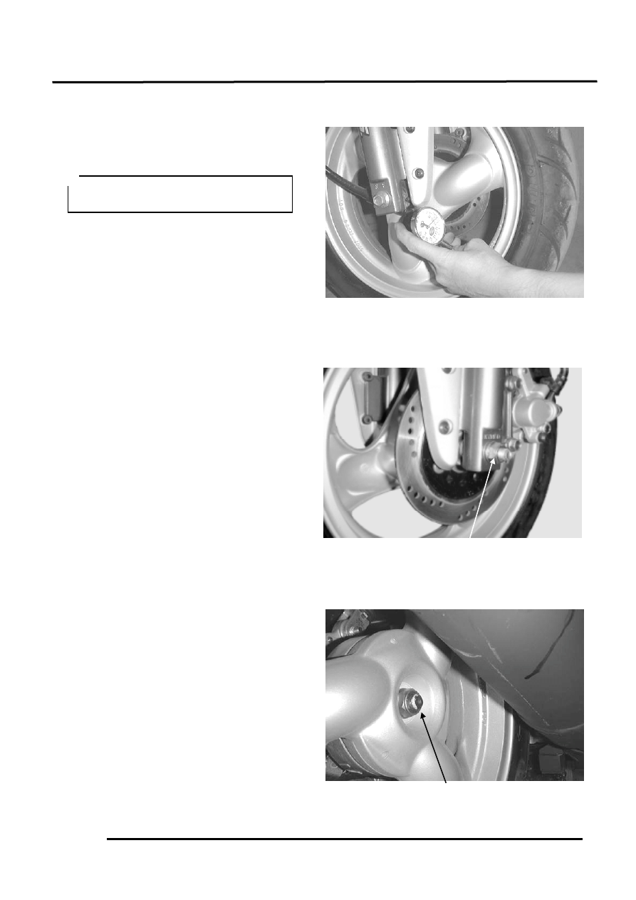
TRANSMISSION CASE
Check the rear wheel transmission case
surrounding area for oil leaks.
Stop the engine and remove the oil check
bolt.
The gear oil level shall be at the oil check
bolt hole. If the oil level is low, add the
specified oil to the proper level.
Specified Gear Oil:
SAE10W90#
Install and tighten the oil check bolt.
Torque: 1.0
1.5kg-m
Start the engine and check for oil leaks.
Oil Check Bolt
Place the motorcycle on its main stand
on level ground.
3
. LUBRICATION SYSTEM
3-7
ELECTRICAL EQUIPMENT
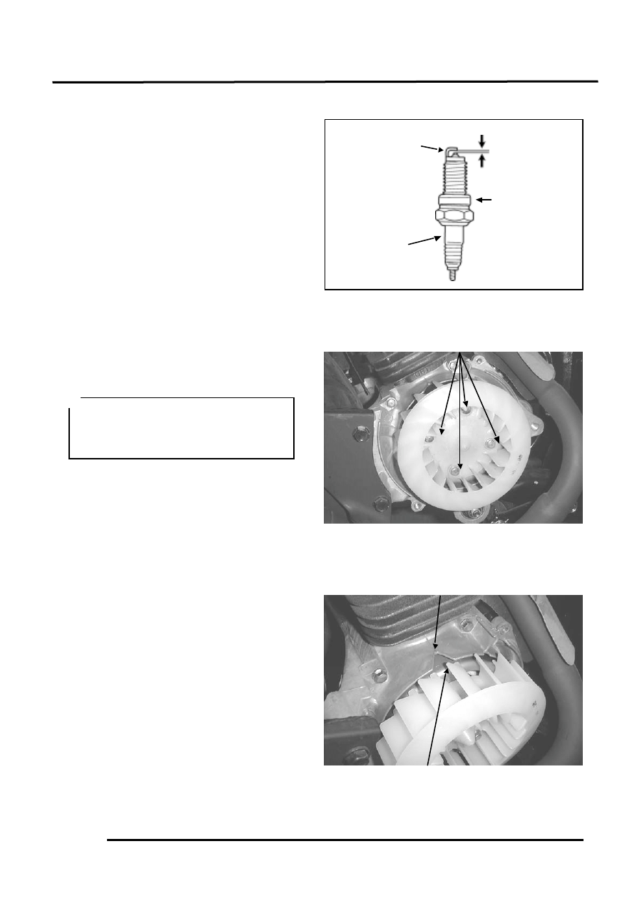
IGNITION APPARATUS
Spark Plug
Remove the frame center cover.
Remove the spark plug cap and spark plug.
Check the spark plug for wear, fouling and
carbon deposits.
Remove the fouling and carbon deposits
with a spark plug cleaner or wire brush.
Specified Spark Plug
BR8HSA
Spark Plug Gap: 0.6
0.7mm
Ignition Apparatus
Remove the right side rail. (!12-4)
Remove the A.C. generator fan cover. (!7-
3)
Remove the four bolts attaching the fan and
then remove the fan.
Warm up the engine and check the ignition
timing with a timing light.
When the engine is running at the specified
rpm, the ignition timing is correct if the “F”
mark on the flywheel aligns with the index
mark on the crankcase within ±2°.
Ignition Timing:
15.5°±2°BTDC/2000rpm
Gap, Wear and
Fouling Deposits
Washer Damage
Cracks
Bolt
Index Mark
The CDI ignition timing is not adjust-
able. If the timing is incorrect, check the
CDI unit, ignition coil and A.C.
generator and replace any faulty parts.
F Mark
0.6-0.7mm
3
. INSPECTION/ADJUSTMENT
3-8
ENGINE
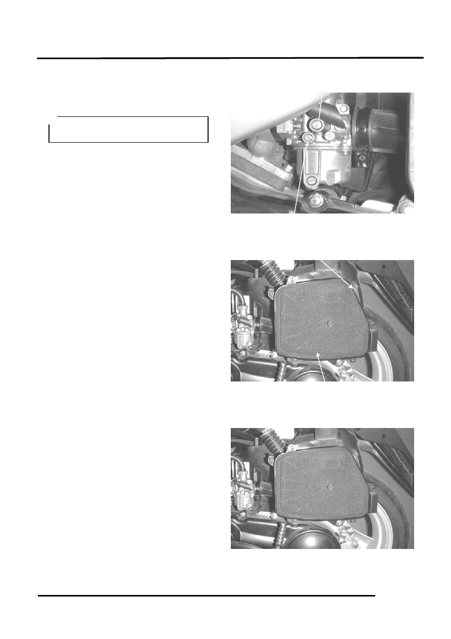
BODY
At High and Low Speeds
Adjust the idle speed to the specified range
by turning the throttle stop screw and air
screw.
Idle Speed:
2100±100rpm
Air Cleaner
Remove the air cleaner cover by removing
the six air cleaner cover screws.
Remove the air cleaner element.
The engine must be warm for accurate
idle speed adjustment.
Air Cleaner
Screws
Air Screw
Throttle Stop Screw
3
. LUBRICATION SYSTEM
3-9
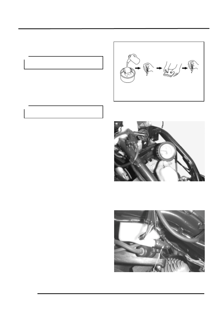
Wash the air cleaner element in detergent
oil, squeeze out and allow to dry.
After washing, soak the element in clean
engine oil SAE 15W-40# and squeeze out
excess oil. Reinstall the element.
Cylinder Compression
Remove the spark plug and insert a
compression gauge.
Open the throttle valve fully and push the
starter button for 7
8 seconds to test
the compression.
Compression:
11.5kg/cm_
If the compression is low, check for the
following:
• Leaking cylinder head gasket
• Worn piston/cylinder
If the compression is high, it indicates that
carbon deposits have accumulated on the
combustion chamber and the piston head.
LUBRICATION SYSTEM
Oil Filter Cleaning
Disconnect the oil tube at the oil pump side
and allow oil to drain into a clean container.
Remove the tube clip at the oil tank side
and disconnect the oil tube.
Remove the oil filter.
Oil Filter
Soak in oil
Squeeze out
and dry
Wash
Squeeze out
excess oil
dry
Warm up the engine before compression
test.
Never use gasoline or organic vaporable
oil with acid or alkali for washing.
Clip
3
. INSPECTION/ADJUSTMENT
3-10
Clean the oil filter screen with compressed
air.
Install the oil filter in the reverse order of
removal and fill the oil tank with specified
oil up to the proper level.
Bleed air from the oil pump and oil lines.
Oil Pump Condition
Open the throttle valve fully and check that
the index mark on the pump body aligns
with the aligning mark on the oil pump
control lever.
Reference tip alignment within 1mm of
index mark on open side is acceptable.
Start and idle the engine, then slowly open
the throttle to increase engine rpm and
check the operation of the oil pump control
lever.
If adjustment is necessary, adjust the oil
pump control cable by loosening the control
cable lock nut and turning the adjusting nut.
After adjustment, tighten the lock nut.
If the oil pump is not synchronized
properly, the following will occur:
• Excessive white smoke or hard starting
due to pump control lever excessively
open
• Seized piston due to pump control lever
insufficiently open
Filter Screen
• Connect the oil tubes securely.
• Install the tube clip at the oil tank side
and also install the clip to the lower oil
tube that goes to the oil pump.
• Check for oil leaks.
Adjust oil pump control cable after the
throttle grip free play is adjusted.
Reference tip alignment within 1mm of
index mark on open side is acceptable.
However, the aligning mark on the
control lever must never be on the closed
side of the index mark, otherwise engine
damage will occur because of insufficient
lubrication.
Adjusting Nut
Lock Nut
Control Lever Aligning Mark
3
. LUBRICATION SYSTEM
3-11
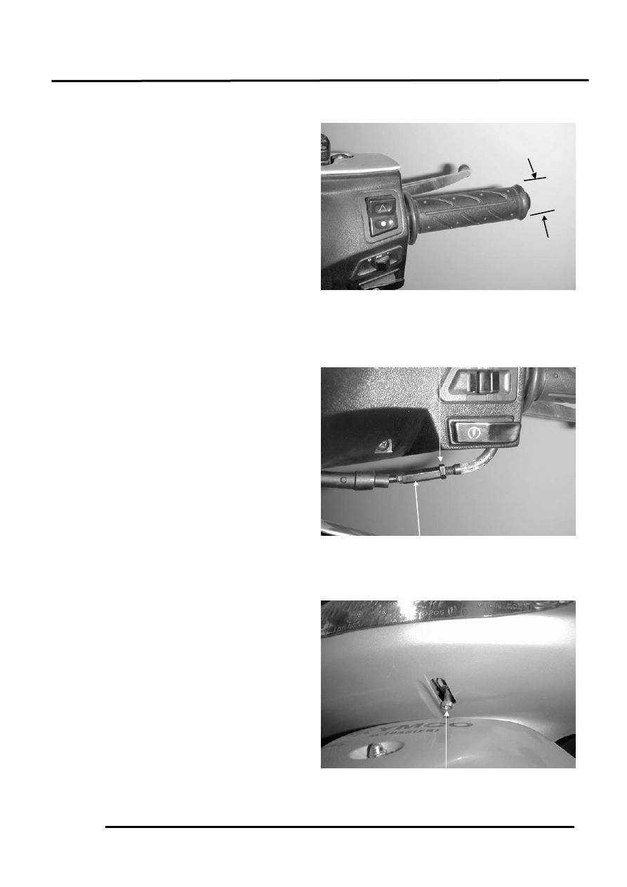
FUEL SYSTEM
Throttle Grip Free Play
Measure the throttle grip free play.
Free Play: 2
6mm
If the throttle grip free play does not fall
within the specified range, adjust by
loosening the lock nut and turning the
adjusting nut.
OTHERS
LIGHTS
Headlight
Adjust the headlight beam by loosening the
headlight adjusting bolt and moving the
adjusting bolt forward and backward to a
proper position. Tighten the adjusting bolt.
Adjusting Nut
Lock Nut
Headlight Adjusting Bolt
Wyszukiwarka
Podobne podstrony:
ZX50 cap 03 (manutenzione)
ZX50 cap 12 (plastiche)
ZX50 cap 09 (riduzione finale)
ZX50 cap 08 (trasmissione)
ZX50 cap 00 (prefazione)
ZX50 cap 04 (lubrificazione)
ZX50 cap 11 (carburatore)
ZX50 cap 07 (statore volano)
ZX50 cap 14 (ruota freno sospensione post)
ZX50 cap 01 (indice e specifiche)
ZX50 cap 16 (strumentazione interruttori luci)
ZX50 cap 13 (manubrio ruota freno sospens ant)
ZX50 cap 02 (info generali)
ZX50 cap 17 (imp scarico)
ZX50 cap 06 (testa cilindro pistone)
ZX50 cap 05 (rimozione motore)
ZX50 cap 15 (imp elettrico)
ZX50 cap 12 (plastiche)
ZX50 cap 09 (riduzione finale)
więcej podobnych podstron