
Micrologic P
Schneider Electric
1
Discovering Micrologic P
4
Identification
4
Presentation
5
Setting procedure
6
Setting Micrologic 5.0 P using the dials
8
Setting Micrologic 6.0 P using the dials
9
Setting Micrologic 7.0 P using the dials
10
Selecting the type of neutral protection
11
Overview of functions
12
Current protection
12
Voltage protection
18
Other protection
19
Load shedding and reconnection
20
Setting dials and buttons
21
Measurements
22
Alarms
24
Optional M2C and M6C contacts
25
Event histories
26
LEDs and display screens
27
COM communications option
29
Setup
30
Setting up the optional M2C / M6C contacts
30
Setting up the Micrologic control unit
32
Setting up the metering functions
35
Setting up the COM communications option
38
Setting up the protection functions
40
Protection settings
42
Fine adjustment of the long-time I
2
t, short-time and
instantaneous settings using the keypad
42
Fine adjustment of the long-time Idmtl, short-time and
instantaneous settings using the keypad
43
Fine adjustment of the earth-fault and earth-leakage
protection setting using the keypad
44
Setting the neutral protection
45
Setting the I
t
, I unbal, max, U min, U max, U unbal, rP max,
F min, F max and phase-rotation protection functions
using the keypad
46
Setting load shedding / reconnection
48
Metering
50
Current measurements
50
Voltage measurements
53
Power measurements
54
Energy measurements
56
Frequency measurements
57
Maintenance
58
Resetting fault indications
58
Viewing the event histories
59
Operation counter and contact-wear indicator
60
Checking the battery
61
Tests
62
Micrologic control units
5.0 P, 6.0 P, 7.0 P
I

Micrologic P
Schneider Electric
2
Menu access
64
Selecting the main menus
64
Metering
66
History, maintenance and setup
68
Protection
71
Technical appendix
74
Tripping curves
74
Zone selective interlocking (ZSI)
76
Power supply
77
Changing the long-time rating plug
79
Thermal memory
80
Data available via the COM communications option
81
Threshold and time-delay settings
82
Other settings
85
Measurement setting ranges and accuracy
86
Index
88

Micrologic P
Schneider Electric
3
Micrologic P
Schneider Electric
4
Discovering Micrologic P
E60230A
E60483A
All Masterpact NT and NW circuit breakers
are equipped with a Micrologic control unit
that can be changed on site.
Control units are designed to protect
power circuits and connected loads.
They offer current, voltage, frequency,
power and energy measurements.
The functions provided by Micrologic 5.0 P,
6.0 P and 7.0 P control units optimise
continuity of service and power
management in your installation.
Identification
E60231A
X: type of protection
c
2 for basic protection
c
5 for selective protection
c
6 for selective + earth-fault protection
c
7 for selective + earth-leakage protection
Y: version number
Identification of the control-unit generation:
"0" signifies the first generation.
Z: type of measurement
c
A for "ammeter"
c
P for "power meter"
c
H for "harmonic meter"
c
no indication = no measurements
Micrologic 5.0 P
Selective protection + Idmtl,
power measurements and additional protection
Selective protection + Idmtl
Micrologic 6.0 P
Selective protection + Idmtl + earth-fault protection,
power measurements and additional protection
Selective protection
+ Idmtl
E60232A
E60231A
0
Ir
I
t
Ii
Isd
Idmtl
0
Ir
I
t
Ii
Isd
Idmtl
Micrologic 7.0 P
Selective protection + Idmtl + earth-leakage protection,
power measurements and additional protection
E60234A
E60231A
E51452A
0
Ir
I
t
Ii
Isd
Idmtl
Selective protection
+ Idmtl
Earth-leakage protection
Micrologic 5.0 P
Y
X
Z
Micrologic 5.0 P
delay
setting
x Ir
2
2.5
3
4
5
6
8
10
Isd
1.5
.4
.5
.6
.7
.8
.9
.95
.98
1
short time
I i
tsd
(s)
on
I
2
t
.
2
.
3
.
4
.
4
.
1
.
2
.
3
.
1
0
off
instantaneous
long time
alarm
Ir
x In
.5
1
2
4
8
12
16
20
tr
(s)
@ 6 Ir
24
x In
test
2
4
10
3
6 8
12
15
off
4260A
N 1 2 3
100
50
0
Micrologic 6.0 P
.4
.5
.6
.7
.8
.9
.95
.98
1
delay
short time
I i
tsd
(s)
on
I
2
t
.
2
.
3
.
4
.
4
.
1
.
2
.
3
.
1
0
off
instantaneous
long time
alarm
Ir
x In
ground fault
B
C
D
E
F
G
H
J
Ig
tg
(s)
on
I
2
t
.
2
.
3
.
4
.
4
.
1
.
2
.
3
.
1
0
off
A
setting
x Ir
2
2.5
3
4
5
6
8
10
Isd
1.5
.5
1
2
4
8
12
16
20
tr
(s)
@ 6 Ir
24
x In
test
2
4
10
3
6 8
12
15
off
4260A
N 1 2 3
100
50
0
Micrologic 7.0 P
.4
.5
.6
.7
.8
.9
.95
.98
1
delay
short time
I i
tsd
(s)
on
I
2
t
.
2
.
3
.
4
.
4
.
1
.
2
.
3
.
1
0
off
instantaneous
long time
alarm
Ir
x In
setting
x Ir
2
2.5
3
4
5
6
8
10
Isd
1.5
.5
1
2
4
8
12
16
20
tr
(s)
@ 6 Ir
24
800
earth leakage
1
2
3
5
7
10
20
30
∆
t
(ms)
60
.5
140
230
350
I
∆
n
(A)
x In
test
2
4
10
3
6 8
12
15
off
4260A
N 1 2 3
100
50
0
0
I
t
I
∆
n
Earth-fault protection
E60233A
0
I
t
I
2
t off
I
2
t on
Ig
Micrologic P
Schneider Electric
5
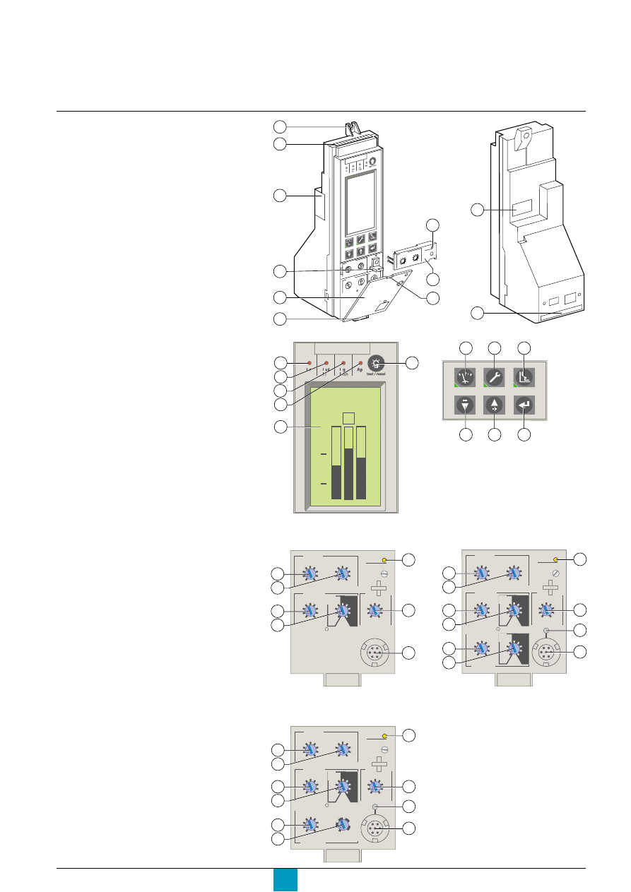
1
top fastener
2
terminal block for external connections
3
housing for battery
4
screw for long-time rating plug
5
long-time rating plug
6
cover opening point
7
protective cover
8
lead-seal fixture for protective cover
9
infrared link with communications interfaces
10
connection with circuit breaker
11
bottom fastener
Indications
12
LED indicating long-time tripping
13
LED indicating short-time or
instantaneous tripping
14
LED indicating earth-fault or
earth-leakage tripping
15
LED indicating additional-protection or
auto-protection tripping
16
graphics display
17
button for reset of fault-trip LED reset
and battery test
Navigation
18
access button to the "Metering" menu (*)
19
access button to the "History, maintenance
and setup" menu (*)
20
access button to the "Protection" menu (*)
21
button used to scroll down or reduce
the displayed value
22
button used to scroll up or increase
the displayed value
23
button used to select or confirm a choice
Adjustement dials
24
long-time current setting Ir
25
long-time tripping delay tr
26
short-time pickup Isd
27
short-time tripping delay tsd
28
instantaneous pickup Ii
29
earth-fault pickup Ig
30
earth-fault tripping delay tg
31
earth-leakage pickup I
∆
n
32
earth-leakage tripping delay
∆
t
33
LED indicating an overload
34
test button for earth-fault and
earth-leakage protection
35
test connector
(
*
)
These buttons include a LED indicating the active menu.
Presentation
E60235A
E60236A
E60237A
Micrologic 5.0 P control unit
Micrologic 6.0 P control unit
E60238A
E60239A
E60240A
7
11
1
2
3
Micr
ologic 5.0 P
.4
.5
.6
.7
.8 .9
.95
.98
1
.5
1
2
4
8 12
16
20
24
long tim
e
alarm
Ir
tr
(s)
x In
at
6 Ir
4
8
6
5
10
9
18
19
20
21
22
23
Micrologic 5.0 P
4260A
N 1 2 3
100
50
0
12
13
14
15
16
17
delay
setting
x Ir
2
2.5
3
4
5
6
8
10
Isd
1.5
.4
.5
.6
.7
.8
.9
.95
.98
1
short time
I i
tsd
(s)
on
I
2
t
.
2
.
3
.
4
.
4
.
1
.
2
.
3
.
1
0
off
instantaneous
long time
alarm
Ir
x In
.5
1
2
4
8
12
16
20
tr
(s)
@ 6 Ir
24
x In
2
4
10
3
6 8
12
15
off
24
25
26
27
33
28
35
.4
.5
.6
.7
.8
.9
.95
.98
1
delay
short time
I i
tsd
(s)
on
I
2
t
.
2
.
3
.
4
.
4
.
1
.
2
.
3
.
1
0
off
instantaneous
long time
alarm
Ir
x In
ground fault
B
C
D
E
F
G
H
J
Ig
tg
(s)
on
I
2
t
.
2
.
3
.
4
.
4
.
1
.
2
.
3
.
1
0
off
A
setting
x Ir
2
2.5
3
4
5
6
8
10
Isd
1.5
.5
1
2
4
8
12
16
20
tr
(s)
@ 6 Ir
24
x In
test
2
4
10
3
6 8
12
15
off
35
33
34
28
24
25
26
27
29
30
Micrologic 7.0 P control unit
E60241A
.4
.5
.6
.7
.8
.9
.95
.98
1
delay
short time
I i
tsd
(s)
on
I
2
t
.
2
.
3
.
4
.
4
.
1
.
2
.
3
.
1
0
off
instantaneous
long time
alarm
Ir
x In
setting
x Ir
2
2.5
3
4
5
6
8
10
Isd
1.5
.5
1
2
4
8
12
16
20
tr
(s)
@ 6 Ir
24
800
earth leakage
1
2
3
5
7
10
20
30
∆
t
(ms)
60
.5
140
230
350
I
∆
n
(A)
x In
test
2
4
10
3
6 8
12
15
off
33
28
34
35
24
25
26
27
31
32
Micrologic P
Schneider Electric
6
Discovering Micrologic P
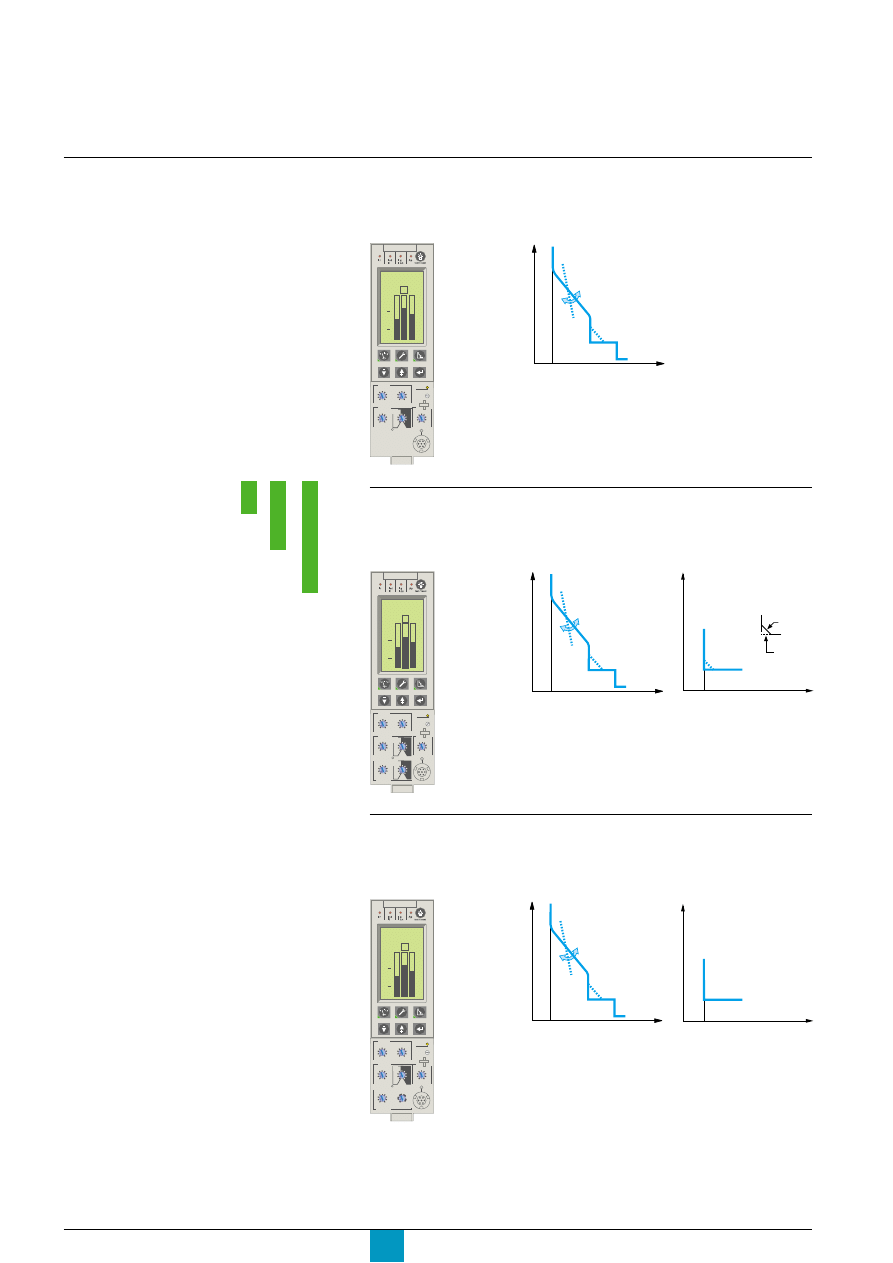
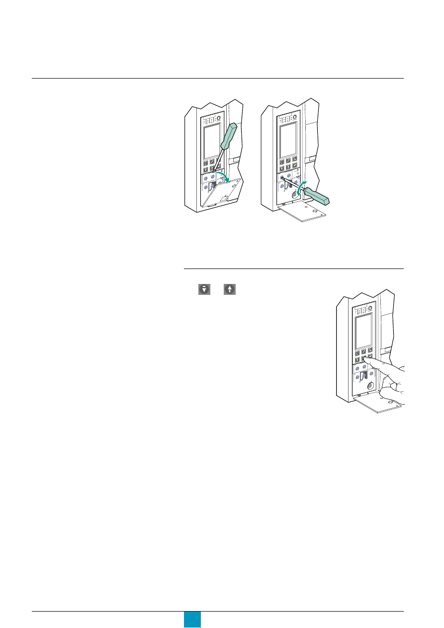
Settings using the dials
E60250A
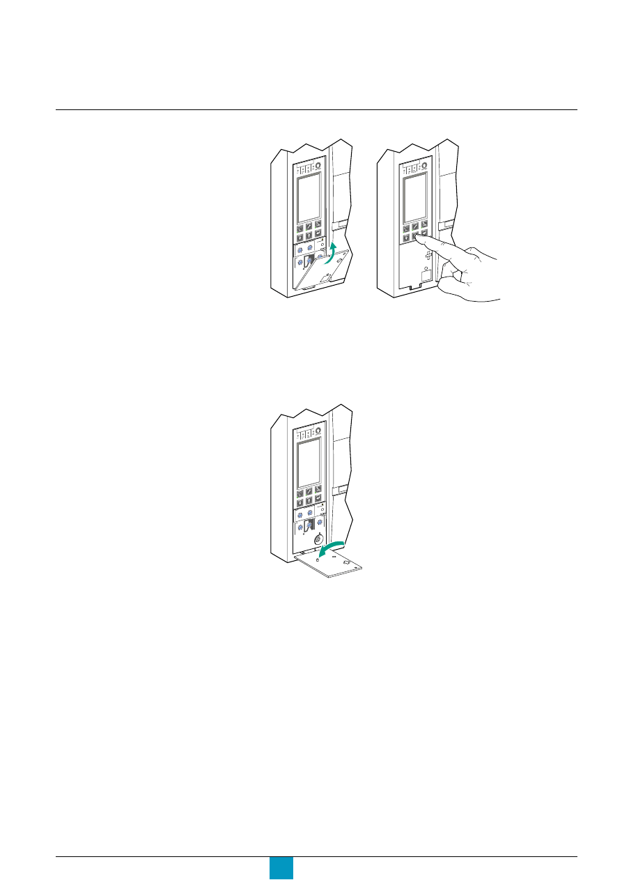
Setting procedure
c
open the protective
cover.
Micr
ologic 5
.0 P
With the protective cover open
Make all the necessary settings for your
control unit.
All fine adjustments are permanently stored
in memory, unless the setting is modified
using the adjustment dial.
For remote settings using the
communications option,
see the "Remote settings" section in the
"Com setup" menu under "History,
maintenance and setup".
E60251A
Micr
ologic 5.0 P
c
make the necessary settings using the dials
c
the screen automatically displays the relevant curve
c
check the set value on the screen, in absolute value
in amperes (A) and in seconds (s).
Settings using the keypad
E60252A
Micr
ologic 5.0 P
c
the and buttons under the screen may be
used for fine adjustments of the settings made using
the dials.
c
all the settings not available via the dials are made
in the same manner, using the keypad.
Caution!
A new setting using one of the dials (including the
neutral selector for four-pole devices):
c
deletes all the fine adjustments previously made
using the keypad for the overload protection
(long time), short-circuit protection (short time and
instantaneous), earth-fault and earth-leakage
protection and neutral protection
c
does not affect any other settings made using the
keypad.
Micrologic P
Schneider Electric
7
With the protective cover closed
Settings may not be made. It is possible to
view the various settings using the keypad
or the communications option.
Caution!
If you notice that the tab on the back of the protective
cover has been broken off, contact the Schneider
after-sales support department to replace the cover.
View the settings and measurements
E60253A
Micr
olog
ic 5.0
P
E60254A
Micr
olog
ic 5.0
P
c
close the protective
cover for the dials
c
access to the dials is
blocked and it is no
longer possible to make
fine adjustments using
the keypad
c
if necessary, install a
lead seal to protect the
settings
c
settings may be viewed
at any time using the
keypad.
E60490A
Micr
ologic 5.0 P
Micrologic P
Schneider Electric
8
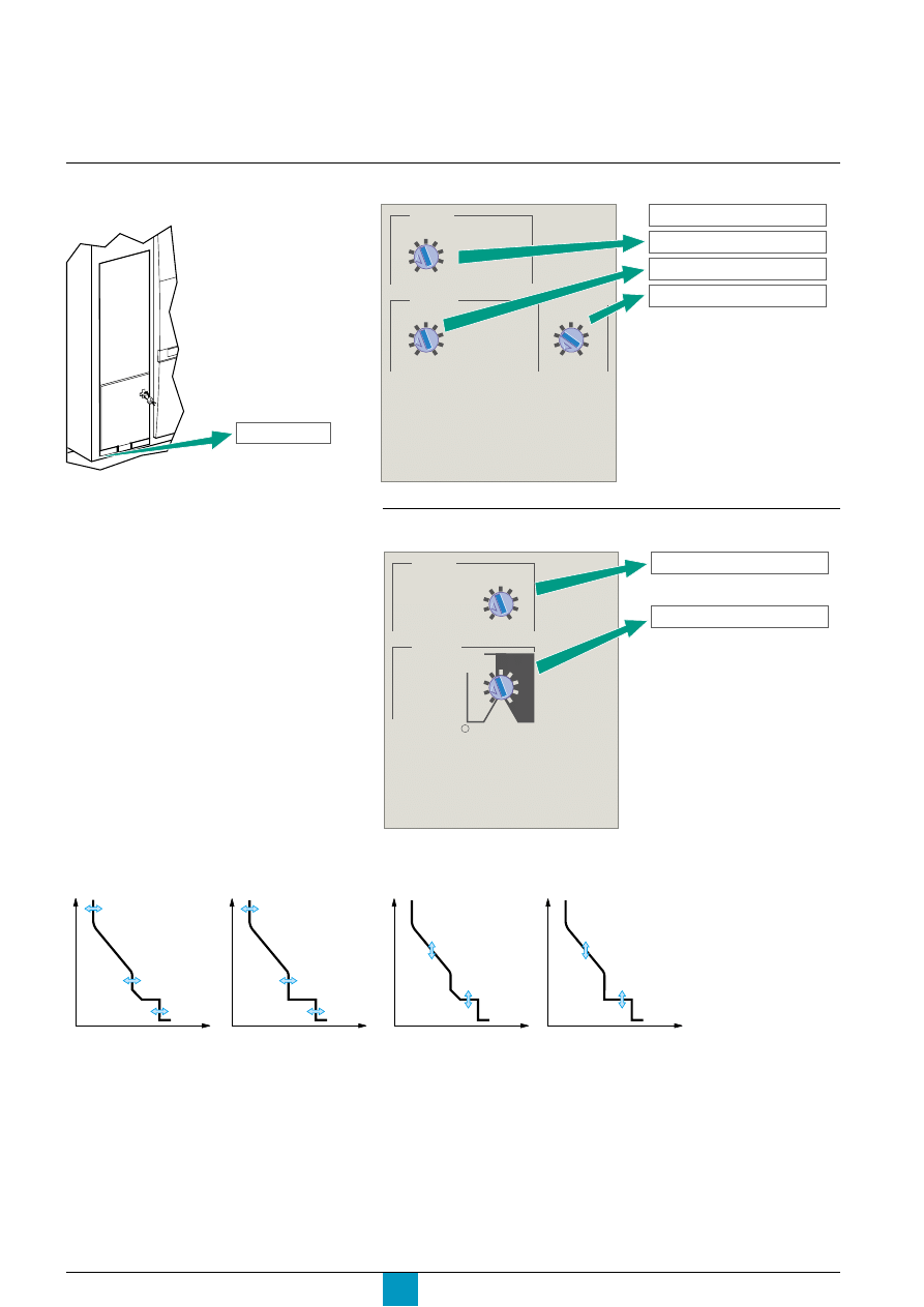
Setting Micrologic 5.0 P
using the dials
Consider a 2000 A circuit breaker.
E60325A
E60445A
1
In = 2000 A
In = 2000 A
See pages 8 and 9 for selection of the
setting ranges.
Set the thresholds
setting
x Ir
2
2.5
3
4
5
6
8
10
Isd
1.5
.4
.5
.6
.7
.8
.9
.95
.98
1
short time
I i
instantaneous
long time
Ir
x In
In = 2000 A
Ir = 0.5 x 2000 = 1000 A
Ii = 2 x 2000 = 4000 A
Isd = 2 x 1000 = 2000 A
x In
2
4
10
3
6 8
12
15
off
Set the time delays
E60326A
delay
short time
tsd
(s)
on
I
2
t
.
2
.
3
.
4
.
4
.
1
.
2
.
3
.
1
0
off
long time
.5
1
2
4
8
12
16
20
tr
(s)
@ 6 Ir
24
tr = 1 s
tsd = 0.2 s
Discovering Micrologic P
E51375A
E51376A
tr
tsd
0
I
t
tr
tsd
0
I
t
I
2
t
ON curve
I
2
t
OFF curve
time delays
tr: LT tripping delay
tsd: ST tripping delay
E51372A
E51373A
Ir
Isd
Ii
0
I
t
Ir
Isd
Ii
0
I
t
I
2
t
ON curve
I
2
t
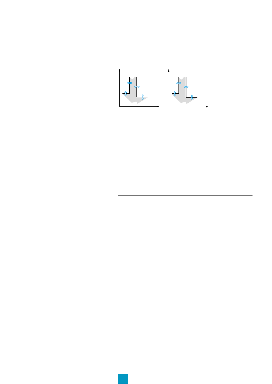
OFF curve
thresholds
Ir: LT threshold
Isd: ST pickup
Ii: Instantaneous pickup
Micrologic P
Schneider Electric
9
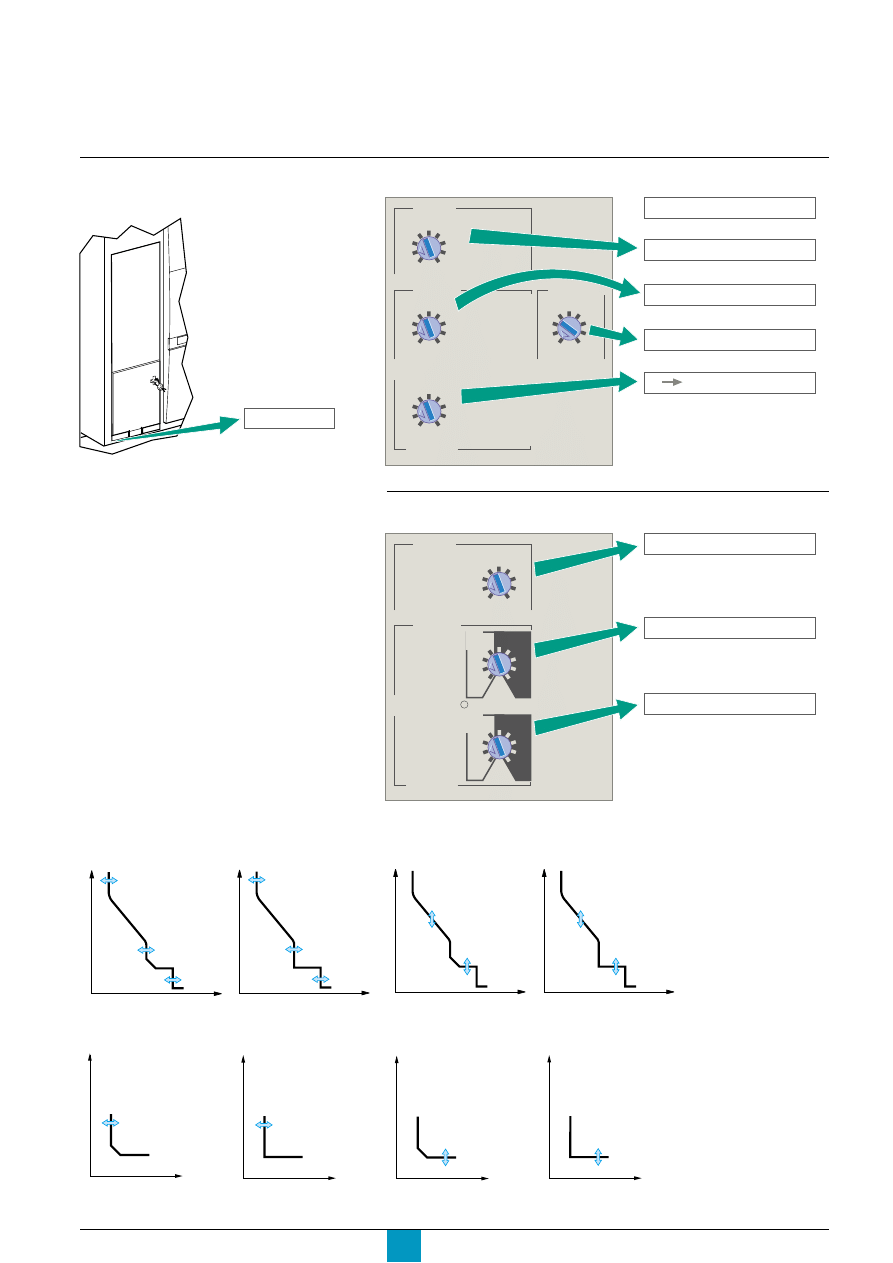
Setting Micrologic 6.0 P
using the dials
Set the thresholds
Set the time delays
E60329A
E60330A
Consider a 2000 A circuit breaker.
E60445A
1
In = 2000 A
In = 2000 A
.4
.5
.6
.7
.8
.9
.95
.98
1
short time
I i
instantaneous
long time
Ir
x In
ground fault
B
C
D
E
F
G
H
J
Ig
A
setting
x Ir
2
2.5
3
4
5
6
8
10
Isd
1.5
x In
2
4
10
3
6 8
12
15
off
In = 2000 A
Ir = 0.5 x 2000 = 1000 A
Ii = 2 x 2000 = 4000 A
Isd = 2 x 1000 = 2000 A
B Ig = 640 A
delay
short time
tsd
(s)
on
I
2
t
.
2
.
3
.
4
.
4
.
1
.
2
.
3
.
1
0
off
long time
ground fault
tg
(s)
on
I
2
t
.
2
.
3
.
4
.
4
.
1
.
2
.
3
.
1
0
off
.5
1
2
4
8
12
16
20
tr
(s)
@ 6 Ir
24
tr = 1 s
tg = 0.2 s
tsd = 0.2 s
See pages 8 to 11 for selection
of the setting ranges.
E51415A
E51416A
0
I
t
Ig
0
I
t
Ig
E51419A
E51418A
0
I
t
tg
0
I
t
tg
E51376A
E51375A
tr
tsd
0
I
t
tr
tsd
0
I
t
time delays
I
2
t
ON curve
I
2
t
OFF curve
E51373A
E51372A
Ir
Isd
Ii
0
I
t
Ir
Isd
Ii
0
I
t
I
2
t
ON curve
I
2
t
OFF curve
thresholds
Ig: earth pickup
Ir: LT threshold
Isd: ST pickup
Ii: Instantaneous pickup
tr: LT tripping delay
tsd: ST tripping delay
tg: earth-fault tripping delay
Micrologic P
Schneider Electric
10
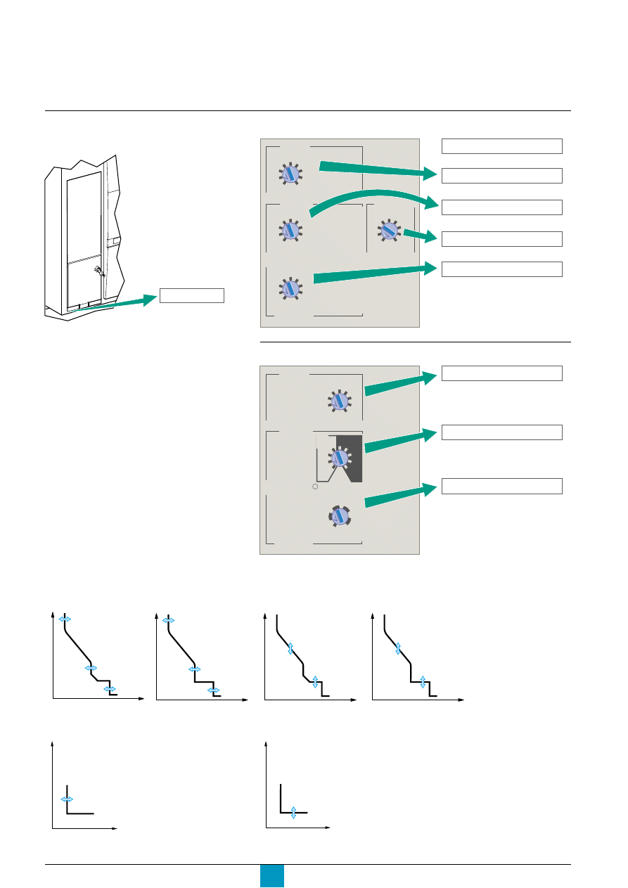
Setting Micrologic 7.0 P
using the dials
Set the thresholds
E60445A
E60333A
Consider a 2000 A circuit breaker.
See pages 8 to 11 for selection of
the setting ranges.
Set the time delays
E60334A
1
In = 2000 A
In = 2000 A
.4
.5
.6
.7
.8
.9
.95
.98
1
short time
I i
instantaneous
long time
Ir
x In
setting
x Ir
2
2.5
3
4
5
6
8
10
Isd
1.5
earth leakage
1
2
3
5
7
10
20
30
.5
I
∆
n
(A)
x In
2
4
10
3
6 8
12
15
off
In = 2000 A
Ir = 0.5 x 2000 = 1000 A
Ii = 2 x 2000 = 4000 A
Isd = 2 x 1000 = 2000 A
I
∆
n = 1 A
delay
short time
tsd
(s)
on
I
2
t
.
2
.
3
.
4
.
4
.
1
.
2
.
3
.
1
0
off
long time
.5
1
2
4
8
12
16
20
tr
(s)
@ 6 Ir
24
800
earth leakage
∆
t
(ms)
60
140
230
350
tr = 1 s
∆
t = 140 ms
tsd = 0.2 s
Discovering Micrologic P
I
2
t
OFF curve
E51376A
E51375A
tr
tsd
0
I
t
tr
tsd
0
I
t
E51423A
time delays
I
2
t
ON curve
0
I
t
∆
t
E51373A
E51372A
Ir
Isd
Ii
0
I
t
Ir
Isd
Ii
0
I
t
I
2
t
ON curve
I
2
t
OFF curve
E51421A
thresholds
0
I
t
I
∆
n
Ir: LT threshold
Isd: ST pickup
Ii: Instantaneous pickup
tr: LT tripping delay
tsd: ST tripping delay
I
∆
n: earth-leakage pickup
∆
t: earth-leakage tripping
delay
E60153A

Micrologic P
Schneider Electric
11
Selection dial on four-pole circuit breakers
On four-pole circuit breakers, it is possible to select the type of neutral protection
for the fourth pole using the three-position dial on the circuit breaker:
c
no neutral protection 4P 3D
c
half neutral protection 3D + N/2
c
full neutral protection 4P 4D.
Selecting the type of neutral
protection
E51383A
4P 3D
3D+N/2
4P 4D

Micrologic P
Schneider Electric
12
Overview of functions
Current protection
I
2
t long-time protection
For the default values, the setting ranges,
increment steps and setting accuracies,
see the technical appendix.
The long-time protection function protects cables against overloads. This function is
based on true rms measurements.
It is possible to select either I
2
t long-time protection or Idmtl long-time protection.
I
2
t long-time protection
Long-time current setting Ir and standard tripping delay tr
Micrologic control unit
Accuracy
5.0 P, 6.0 P and 7.0 P
current setting
Ir = In x …(*)
0.4
0.5
0.6
0.7
0.8
0.9
0.95
0.98
1
tripping betweeen 1.05 and 1.20 Ir
other ranges or disable by changing rating plug
time delay (s)
tr at 1.5 x Ir
0 to - 30%
12.5
25
50
100
200
300
400
500
600
tr at 6 x Ir
0 to - 20%
0.5
1
2
4
8
12
16
20
24
tr at 7.2 x Ir
0 to - 20%
0.34
0.69
1.38
2.7
5.5
8.3
11
13.8
16.6
* In: circuit breaker rating
c
it is possible to enhance the Ir setting accuracy (reduced range) or disable the
long-time protection function by using a different long-time rating plug.
See the technical appendix "Changing the long-time rating plug".
Thermal memory
c
the thermal memory continuously accounts for the amount of heat in the cables,
both before and after tripping, whatever the value of the current (presence of an
overload or not). The thermal memory optimises the long-time protection function of
the circuit breaker by taking into account the temperature rise in the cables.
c
the thermal memory assumes a cable cooling time of approximately 15 minutes.

Micrologic P
Schneider Electric
13
c
neutral protection
Overload protection (long time) for the neutral is disabled if the Idmtl protection
function is selected. However, the short-circuit protection (short time and
instantaneous) remains operational.
c
intermittent overloads
As long as the Micrologic P control unit remains supplied with power, the effects of
intermittent overloads on cables are calculated. If power is cut, temperature rise in
cables is not calculated.
Idmtl long-time protection
Idmtl Protection
Long-time current setting Ir and Idmtl tripping delay tr
Micrologic control unit
Accuracy
5.0 P, 6.0 P and 7.0 P
current setting
Ir = In x …(*)
0.4
0.5
0.6
0.7
0.8
0.9
0.95
0.98
1
tripping between 1.05 and 1.20 Ir
other ranges or disable by changing rating plug
DT
time delay (s)
tr at 1.5 x Ir
0 to - 20%
0.5
1
2
4
8
12
16
20
24
tr at 6 x Ir
0 to - 20%
0.5
1
2
4
8
12
16
20
24
tr at 7.2 x Ir
0 to - 20%
0.5
1
2
4
8
12
16
20
24
SIT
time delay (s)
tr at 1.5 x Ir
0 to - 30%
1.9
3.8
7.6
15.2
30.4
45.5 60.7
75.8
91
tr at 6 x Ir
0 to - 20%
0.5
1
2
4
8
12
16
20
24
tr at 7.2 x Ir
0 to - 20%
0.44
0.88
1.77
3.54
7.08
10.6 14.16 17.7
21.2
VIT
time delay (s)
tr at 1.5 x Ir
0 to - 30%
3.6
7.2
14.4
28.8
57.7
86.5 115.4 144.2 173.1
tr at 6 x Ir
0 to - 20%
0.5
1
2
4
8
12
16
20
24
tr at 7.2 x Ir
0 to - 20%
0.4
0.81
1.63
3.26
6.52
9.8
13.1
16.34 19.61
EIT
time delay (s)
tr at 1.5 x Ir
0 to - 30%
12.5
25
50
100
200
300
400
500
600
tr at 6 x Ir
0 to - 20%
0.5
1
2
4
8
12
16
20
24
tr at 7.2 x Ir
0 to - 20%
0.34
0.69
1.38
2.7
5.5
8.3
11
13.8
16.6
HVF
time delay (s)
tr at 1.5 x Ir
0 to - 30%
164.5 329
658
1316
2632
3950 5265
6581
7900
tr at 6 x Ir
0 to - 20%
0.5
1
2
4
8
12
16
20
24
tr at 7.2 x Ir
0 to - 20%
0.24
0.48
0.96
1.42
3.85
5.78 7.71
9.64
11.57
* In: circuit breaker rating
c
these curves with different slopes are used to improve:
v
discrimination with fuses positioned upstream (HV) and/or downstream
v
protection for certain types of loads
c
five types of curves are available:
v
DT: definite time curve
v
SIT: standard inverse time curve (I
0.5
t)
v
VIT: very inverse time curve (It)
v
EIT: extremely inverse time curve (I
2
t)
v
HVF: compatible with high-voltage fuses (I
4
t).
Micrologic P
Schneider Electric
14
Overview of functions
Current protection
Short-time and instantaneous
protection
For the default values, the setting ranges,
increment steps and setting accuracies,
see the technical appendix.
Short-time protection
c
the short-time protection function protects the distribution system against
impedant short-circuits
c
the short-time tripping delay can be used to ensure discrimination with a
downstream circuit-breaker
c
this function carries out true rms measurements.
c
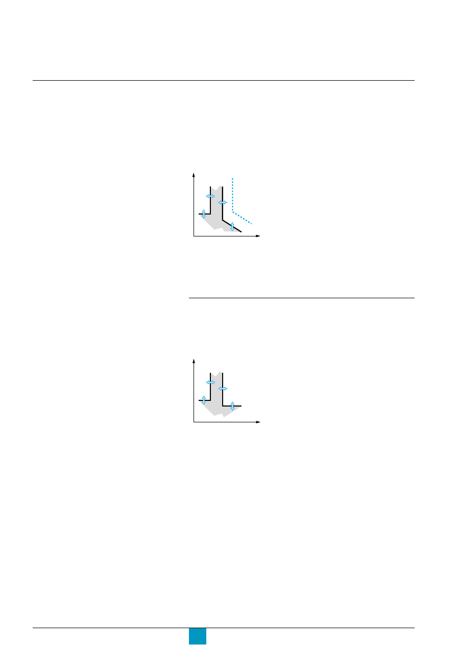
the I
2
t ON and I
2
t OFF options enhance discrimination with downstream
protection devices
c
use of I
2
t curves with short-time protection:
v
I
2
t OFF selected: the protection function implements a constant time curve
v
I
2
t ON selected: the protection function implements an I
2
t inverse-time curve up to
10 Ir. Above 10 Ir, the time curve is constant.
c
zone selective interlocking (ZSI)
The short-time and earth-fault protection functions enable time discrimination by
delaying the upstream devices to provide the downstream devices the time
required to clear the fault. Zone selective interlocking can be used to obtain total
discrimination between circuit breakers using external wiring.
The portable test kit can be used to test the wiring between circuit breakers for the
zone selective interlocking function.
Short-time pickup Isd and tripping delay tsd
Micrologic control unit
5.0 P, 6.0 P and 7.0 P
pickup
Isd = Ir x ...
1.5
2
2.5
3
4
5
8
10
accuracy
±
10 %
time delay (ms)
setting
I
2
t Off
0
0.1
0.2
0.3
0.4
at 10 Ir
I
2
t On
0.1
0.2
0.3
0.4
I
2
t On or
tsd (max resettable time)
20
80
140
230
350
I
2
t Off
tsd (max break time)
80
140
200
320
500
For the characteristics and external wiring
of the zone selective interlocking function,
see the technical appendix on "Zone
selective interlocking".
Instantaneous protection
c
the instantaneous-protection function protects the distribution system against
solid short-circuits. Contrary to the short-time protection function, the tripping delay
for instantaneous protection is not adjustable. The tripping order is sent to the
circuit breaker as soon as current exceeds the set value, with a fixed time delay of
20 milliseconds.
c
this function carries out true rms measurements.
Instantaneous pickup Ii
Micrologic control unit
5.0 P, 6.0 P and 7.0 P
pickup
Ii = In x ... (*)
2
3
4
6
8
10
12
15
OFF
accuracy
±
10 %
* In: circuit-breaker rating
c
circuit breakers have two types of instantaneous protection:
v
adjustable instantaneous protection Ii
v
self-protection.
Depending on the circuit breaker, the OFF position corresponds to
the self-protection pickup.
If the "without long-time protection" plug is used and the long-time protection
function is disabled, the short-time pickup Isd is automatically multiplied by In
instead of Ir as is the standard case.
Micrologic P
Schneider Electric
15
Three-pole circuit breakers
Protection of the neutral is possible on a three-pole circuit breaker by connecting
an external sensor.
Settings are made using the and buttons on the control unit.
For the default values, the setting ranges,
increment steps and setting accuracies,
see the technical appendix.
Neutral protection
Micrologic control unit
5.0 P, 6.0 P and 7.0 P
Setting
OFF
N/2
N
Nx2
Type of neutral
Description
No neutral protection
The distribution system does not require protection
of the neutral conductor.
Half neutral protection
The cross-sectional area of the neutral conductor is half that
of the phase conductors.
c
the long-time current setting Ir for the neutral is equal to
half the setting value
c
the short-time pickup Isd for the neutral is equal to half
the setting value
c
the instantaneous pickup Ii for the neutral is equal to
the setting value
c
for earth-fault protection (Micrologic 6.0 P), pickup Ig for
the neutral is equal to the setting value.
Full neutral protection
The cross-sectional area of the neutral conductor is equal to
that of the phase conductors.
c
the long-time current setting Ir for the neutral is equal to
the setting value
c
the short-time pickup Isd for the neutral is equal to the
setting value
c
the instantaneous pickup Ii for the neutral is equal to the
setting value
c
for earth-fault protection (Micrologic 6.0 P), pickup Ig for
the neutral is equal to the setting value.
Double neutral protection In installations with a high level of third-order harmonic
currents (or multiples thereof), the current in the neutral
conductor may exceed that of the phase currents under
steady-state conditions
c
the long-time current setting Ir for the neutral is double
that of the setting value
c
the short-time pickup Isd for the neutral is double that of
the setting value, but may not exceed 10 In to limit
transients and self-protect the installation
c
the instantaneous pickup Ii for the neutral is equal to
the setting value
c
for earth-fault protection (Micrologic 6.0 P), pickup Ig for
the neutral is equal to the setting value.
Micrologic control unit
5.0 P, 6.0 P and 7.0 P
Setting
OFF
N/2
N
Type of neutral
Description
No neutral protection
The distribution system does not require protection of the
neutral conductor.
Half neutral protection
The cross-sectional area of the neutral conductor is half that
of the phase conductors.
c
the long-time current setting Ir for the neutral is equal to
half the setting value
c
the short-time pickup Isd for the neutral is equal to half
the setting value
c
the instantaneous pickup Ii for the neutral is equal to the
setting value
Full neutral protection
The cross-sectional area of the neutral conductor is equal
to that of the phase conductors.
c
the long-time current setting Ir for the neutral is equal to
the setting value
c
the short-time pickup Isd for the neutral is equal to the
setting value
c
the instantaneous pickup Ii for the neutral is equal to
the setting value.
Four-pole circuit breakers
The initial protection setting is made using the dial on the neutral pole of the circuit
breaker.
The
and buttons on the control unit may then be used for a more precise
setting. The dial setting constitutes the upper limit for adjustments using the keypad.

Micrologic P
Schneider Electric
16
Current protection
Earth-fault and earth-leakage
protection
Earth-fault protection on Micrologic 6.0 P
c
an earth fault in the protection conductors can provoke local temperature rise at
the site of the fault or in the conductors. The purpose of the earth-fault protection
function is to eliminate this type of fault.
c
there are two types of earth-fault protection.
For the default values, the setting ranges,
increment steps and setting accuracies,
see the technical appendix.
Type
Description
Residual
c
the function determines the zero-phase sequence
current, i.e. the vector sum of the phase and neutral
currents (depending on the type of installation).
Source Ground Return
c
using a special external sensor, this function directly
measures the fault current returning to the transformer
via the earth cable
c
it detects faults both upstream and downstream of
the circuit breaker
c
the maximum distance between the sensor and the
circuit breaker is ten metres.
c
earth-fault and neutral protection are independent and can therefore be
combined.
Earth-fault pickup Ig and tripping delay tg
The pickup and tripping-delay values can be set independently and are identical for
both the residual and "source ground return" earth-fault protection functions.
Micrologic control unit
6.0 P
pickup
Ig = In x ...
A
B
C
D
E
F
G
H
I
accuracy
±
10 %
In
≤
400 A
0.3
0.3
0.4
0.5
0.6
0.7
0.8
0.9
1
400 A < In
≤
1200 A
0.2
0.3
0.4
0.5
0.6
0.7
0.8
0.9
1
In > 1200 A
500 A
640 A
720 A
800 A
880 A
960 A
1040 A 1120 A 1200 A
time delay (ms)
settings
I
2
t Off
0
0.1
0.2
0.3
0.4
at 10 In
I
2
t On
0.1
0.2
0.3
0.4
I
2
t On or
tg (max resettable time)
20
80
140
230
350
I
2
t Off
tg (max. break time)
80
140
200
320
500
Earth-leakage protection on sur Micrologic 7.0 P
c
the earth-leakage protection function primarily protects people against indirect
contact because an earth-leakage current can provoke an increase in the potential
of the exposed conductive parts. The earth-leakage pickup value I
∆
n is displayed
directly in amperes and the tripping delay follows a constant-time curve.
c
an external rectangular sensor is required for this function
c
this function is inoperative if the long-time rating plug is not installed
v
d
Protected against nuisance tripping
v
k
DC-component withstand class A up to 10 A.
Pickup value I
∆
n and tripping delay
∆
t
Micrologic control unit
7.0 P
pickup (A)
I
∆
n
0.5
1
2
3
5
7
10
20
30
accuracy 0 to - 20 %
time delay (ms)
settings
∆
t (max resettable time)
60
140
230
350
800
∆
t (max. break time)
140
200
320
500
1000
Overview of functions
Micrologic P
Schneider Electric
17
I
t
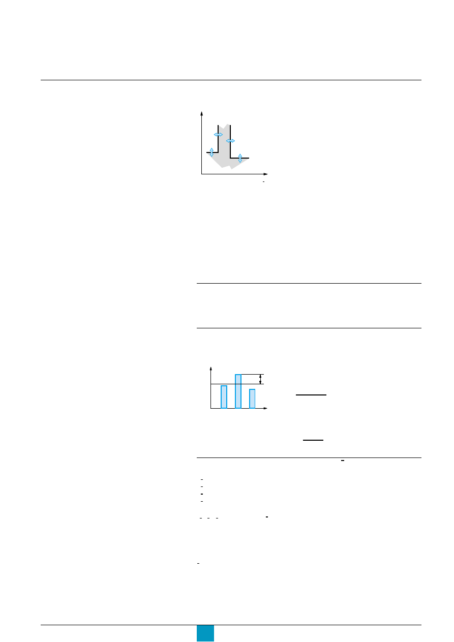
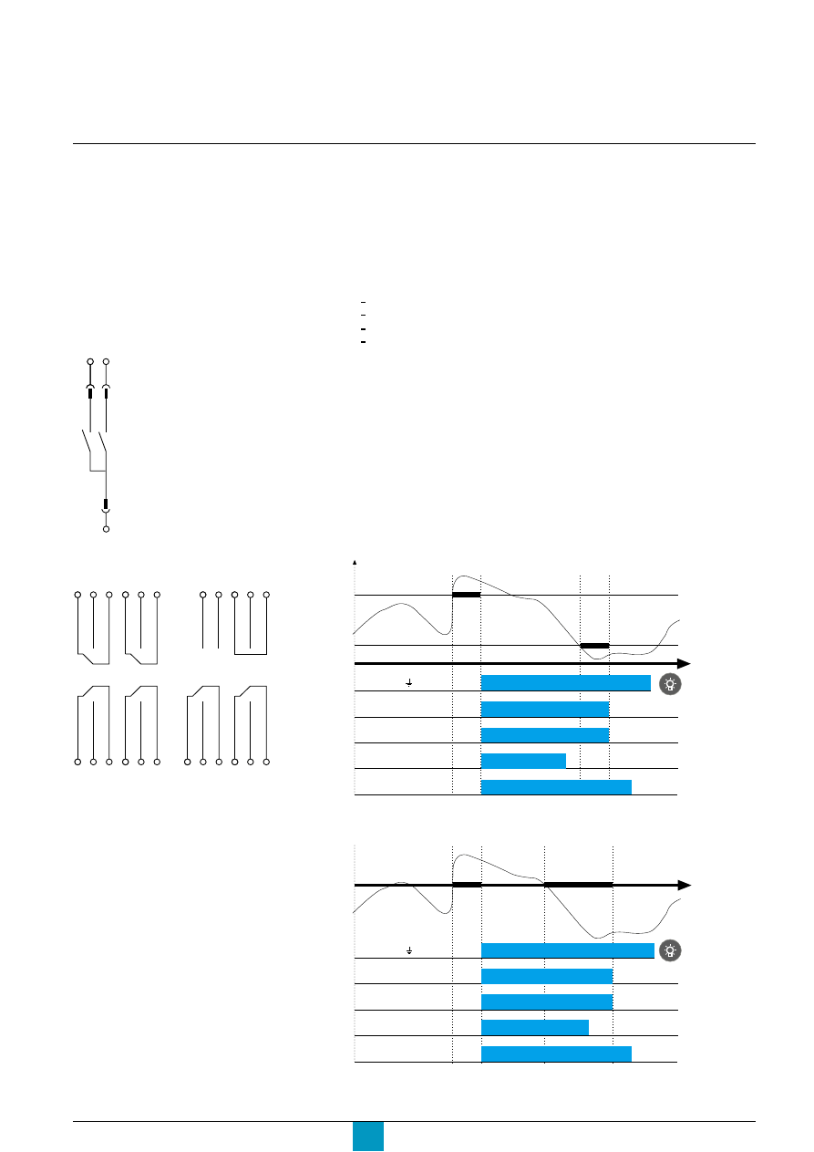
Alarm, current unbalance,
maximum current
Operating principle
protection tripped by a maximum value
E71740A
For the pickup and dropout thresholds and
time delays, see the technical appendix.
1: pickup threshold
2: pickup time delay
3: dropout threshold
4: dropout time delay
c
for protection tripped by a maximum value, it is possible to set:
v
a pickup threshold (1) that activates an alarm, a contact and/or tripping
v
a pickup time delay (2) that steps in when the pickup threshold (1) is reached
v
a dropout threshold (3) corresponding to deactivation of the alarm and/or contact
v
a dropout time delay (4) that steps in when the dropout threshold (3) is reached
c
the dropout threshold is always less than or equal to the pickup threshold.
I
t
t
t
t
t
Alarm
c
the alarm function is tripped by the rms value of an earth-leakage current
c
this alarm signals an earth-leakage current under the pickup value and does not
produce circuit-breaker tripping.
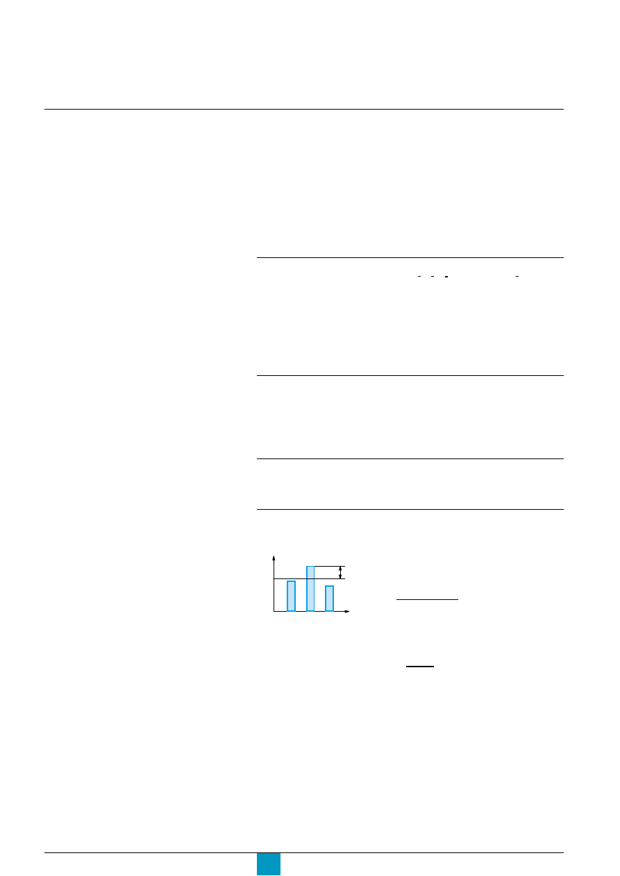
Current-unbalance protection I unbal
c
this protection is activated by an adjustable level of unbalance between the RMS
values of the three phase currents.
E71749A
c
from:
v
I avg is the average value of the rms currents of the
three phases
I avg =
I1 + I2 + I3
3
I unbal =
v
E max is the maximum difference between the
current of each phase and I avg
c
Micrologic P uses the two values above to calculate
the current unbalance:
I
I
1
0
I
t
Alarm, I unbal,
I max
t
3
2
4
0
I
I1
I2
I3
I avg
E max
Maximum-current protection per phase max
c
protection values may be set for each of the following currents:
v
1 max: maximum current on phase 1
v
2 max: maximum current on phase 2
v
3 max: maximum current on phase 3
v
N max: maximum current in the neutral
c
this function calculates the rms demand value of the current for the given phase
( 1, 2, 3) or the neutral ( N), over a sliding time interval.
The time interval is the same as that for the calculation of the demand currents in
the "Metering" menu.
Settings are made in the "Metering setup" menu.
Note:
IN max protection does not take into account the neutral-protection setting (N, N/2, Nx2, OFF).
I
I
I
I
I
I
I
E max
I avg
Micrologic P
Schneider Electric
18
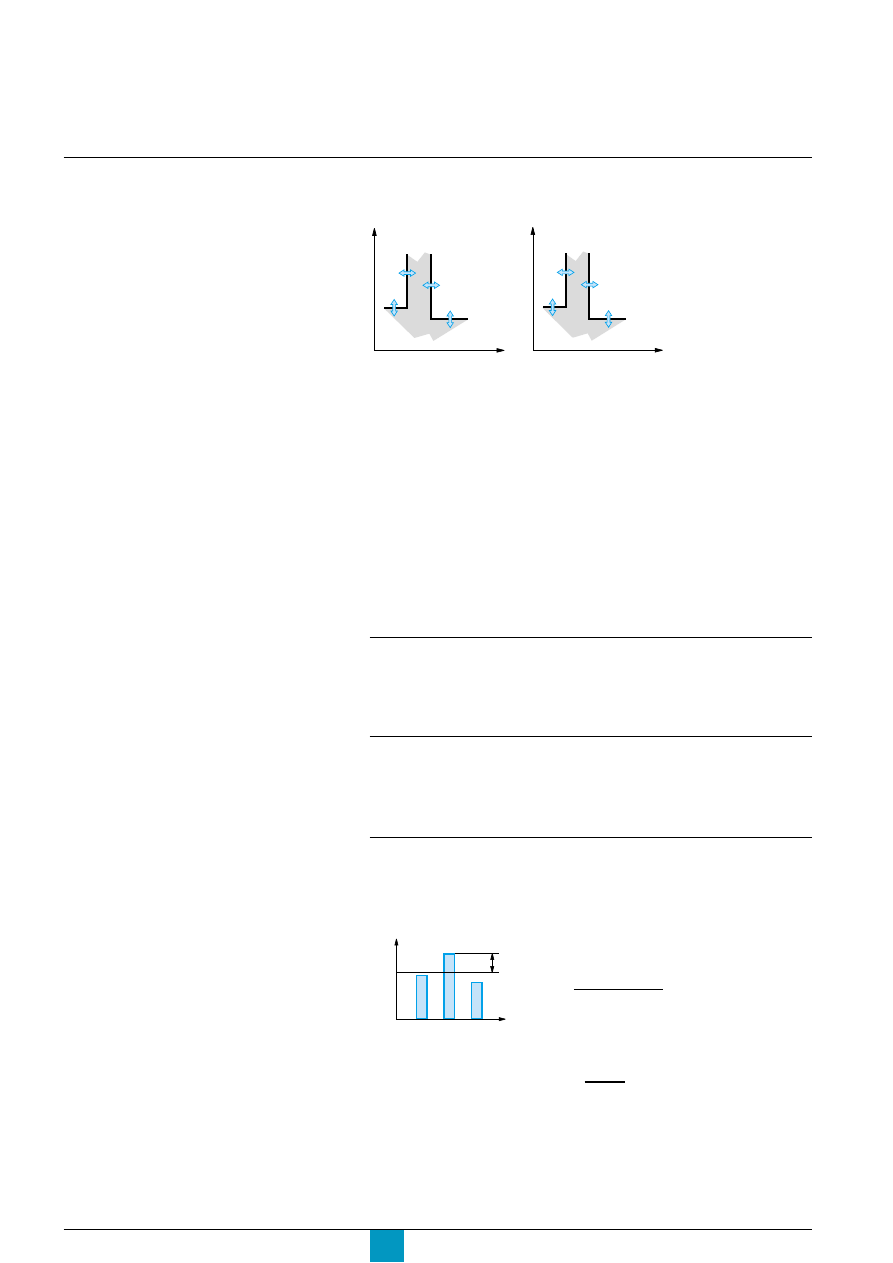
Voltage protection,
Minimum voltage, maximum voltage,
voltage unbalance
For the pickup and dropout thresholds and
time delays, see the technical appendix.
Operating principle
protection tripped
by a minimum value
1: pickup threshold
2: pickup time delay
3: dropout threshold
4: dropout time delay
c
for protection tripped by a minimum or maximum value, it is possible to set:
v
a pickup threshold (1) that activates an alarm, a contact and/or tripping
v
a pickup time delay (2) that steps in when the pickup threshold (1) is reached
v
a dropout threshold (3) corresponding to deactivation of the alarm and/or contact
v
a dropout time delay (4) that steps in when the dropout threshold (3) is reached
c
for protection tripped by a minimum value, the dropout threshold is always greater
than or equal to the pickup threshold
c
for protection tripped by a maximum value, the dropout threshold is always less
than or equal to the pickup threshold
c
if both the minimum and maximum protection functions are activated at the same
time, the minimum threshold is automatically limited to the value of the maximum
and vice versa.
Minimum-voltage protection U min
c
this function calculates the minimum rms value of the three phase-to-phase
voltages
c
protection is activated when the three phase-to-phase voltages (U12, U23, U31)
are simultaneously below the threshold set by the user.
Maximum-voltage protection U max
c
this function calculates the maximum rms value of the three phase-to-phase
voltages
c
protection is activated when the three phase-to-phase voltages (U12, U23, U31)
are simultaneously above the threshold set by the user.
Voltage-unbalance protection U unbal
This protection is activated by an adjustable level of unbalance between the rms
values of the three phase-to-phase voltages.
This function calculates the rms value of the unbalance between the three phase-
to-phase voltages.
E71742A
c
from:
v
U avg is the average value of the rms voltages of the
three phases
v
E max: is the maximum difference between the
voltage of each phase and U avg
c
Micrologic P uses the two values above to calculate
the voltage unbalance:
U unbal =
U avg =
U12 + U23 + U31
3
Overview of functions
E60489A
1
0
U min
t
3
2
4
protection tripped
by a maximum value
E71741A
1
0
U max
U unbal.
t
3
2
4
0
U
U12
U23
U31
U avg
E max
E max
U avg
Micrologic P
Schneider Electric
19
1
0
F min
t
3
2
4
Other protection
Reverse power, min. frequency,
max. frequency, phase rotation
For the pickup and dropout thresholds and
time delays, see the technical appendix.
Operating principle
protection tripped
by a minimum value
E60487A
1: pickup threshold
2: pickup time delay
3: dropout threshold
4: dropout time delay
c
for protection tripped by a minimum or maximum value, it is possible to set:
v
a pickup threshold (1) that activates an alarm, a contact and/or tripping
v
a pickup time delay (2) that steps in when the pickup threshold (1) is reached
v
a dropout threshold (3) corresponding to deactivation of the alarm and/or contact
v
a dropout time delay (4) that steps in when the dropout threshold (3) is reached
c
for protection tripped by a minimum value, the dropout threshold is always greater
than or equal to the pickup threshold
c
for protection tripped by a maximum value, the dropout threshold is always less
than or equal to the pickup threshold
c
if both the minimum and maximum protection functions are activated at the same
time, the minimum threshold is automatically limited to the value of the maximum
and vice versa.
Reverse-power protection rP max
c
this function calculates the value of the total active power on the three phases
c
the function is activated when the total active power of the three phases flows in
the direction opposite that set by the user is greater than the pickup threshold (1)
for a time greater than the time delay (2).
Note:
The direction of flow is set by the user in the "Power flow" section of the "Protection setup"
menu under "History, maintenance and settings".
c
"Top fed" corresponds to the normal direction of flow, i.e. from the top terminals on the circuit
breaker to the bottom terminals
c
"Bottom fed" is the opposite.
Minimum and maximum-frequency protection F min.
and F max
These functions monitor the value of the frequency on the distribution system.
Phase-rotation protection
This protection function is actived if two of the three phases are inverted.
Note:
The function is activated following a fixed 300-millisecond time delay. If one of the phases is
absent, the function is disabled.
E60486A
1
0
F max
rP max
t
3
2
4
protection tripped
by a maximum value
Micrologic P
Schneider Electric
20
Overview of functions
Load shedding
and reconnection
For the pickup and dropout thresholds and
time delays, see the technical appendix.
Load shedding and reconnection depending on current
The pickup curve for load shedding and reconnection depending on current is
parallel to the LT I
2
t and Idmtl curves.
c
I
2
t protection: the neutral is taken into account
c
Idmtl: the neutral is not taken into account.
This function does not trip the circuit breaker, but can be used to set off an alarm
linked to an M2C or M6C contact (disconnection and reconnection of non-priority
loads).
The load-shedding and reconnection function is determined by thresholds and time
delays.
1: pickup threshold
2: pickup time delay
3: dropout threshold
4: dropout time delay
The pickup threshold is always greater than or equal to the dropout threshold.
Load shedding and reconnection depending on power
Load shedding and reconnection depending on power calculates the total active
power on the three phases. This function does not trip the circuit breaker, but can
be used to set off an alarm linked to an M2C or M6C contact (disconnection and
reconnection of non-priority loads).
The load-shedding and reconnection function is determined by thresholds and time
delays.
E60249A
3
0
P
t
1
4
4
1: pickup threshold
2: pickup time delay
3: dropout threshold
4: dropout time delay
The pickup threshold is always greater than or equal to the dropout threshold.
E71754A
3
0
I
t
1
4
2
Long-time
protection
curve

Micrologic P
Schneider Electric
21
Setting dials and buttons
Dials
c
dials are used to set thresholds and time delays for protection functions against
overloads, short-circuits and earth faults or earth leakage on Micrologic P control
units
c
if the set thresholds are overrun, these functions systematically trip the circuit
breaker.
Buttons
c
buttons on the keypad are subsequently used for fine adjustment of the
thresholds and time delays for the functions listed above, i.e. to intermediate values
between the dial settings. The value previously set using a dial automatically
becomes the maximum value for keypad settings
c
buttons are also used to activate the other protection functions offered by
Micrologic P (not activated in the basic factory configuration). These functions are
not accessible via the dials.
Micrologic P
Schneider Electric
22
Measurements
Current and voltage
For the setting ranges and measurement
accuracies, see the technical appendix.
To display the phase-to-neutral voltages,
select the "3
Φ
4w 4CT" option in "System
type" in the "Metering setup" menu under
"History, maintenance and setup".
Instantaneous current I inst.
Micrologic P control units offer two, non-exclusive possibilities.
c
display of the instantaneous current on the bargraph
The unit automatically displays the values in amperes for phases 1, 2 and 3 and
the neutral (depending on the type of distribution system). The bargraph also
indicates the most heavily loaded phase.
c
current measurements
v
measurement in amperes of the instantaneous currents I (rms) on phases I1, I2
and I3 and the neutral current IN, the earth-fault current Ig (Micrologic 6.0 P), the
earth-leakage current I
∆
n (Micrologic 7.0 P)
v
the maximum value of each current is stored in memory (maximeter)
v
the maximeter can be reset.
Demand current I demand
c
display of the demand current on phases 1, 2, 3 and the neutral N
(depending on the type of distribution system)
c
display of the interval over which the value is calculated
c
the maximum demand value is stored in memory (maximeter)
c
the maximeter can be reset.
Note:
The interval for calculation of the demand value over a sliding window may be set in the
"Metering setup" menu under "History, maintenance and setup".
Phase-to-neutral and phase-to-phase voltages
Micrologic P offers different voltage measurements:
c
phase-to-phase voltages (rms): measurement in volts of the voltage between
phases U12, U23 and U31
c
phase-to-neutral voltages (rms): measurement in volts of the voltage between the
phases and the neutral U1N, U2N and U3N.
Average voltage U avg
Average voltage: measurement in volts of the average voltage between phases
U12, U23 and U31.
Voltage unbalance U unbal
This function calculates the percentage of the unbalance between the three
phase-to-phase voltages.
I
I
I
I
Overview of functions
c
from:
v
U avg is the average value of the rms voltages of
the three phases
v
E max is the maximum difference between the
voltage of each phase and U avg
c
Micrologic P uses the two values above to calculate
the voltage unbalance
U unbal =
U avg =
U12 + U23 + U31
3
E71742A
0
U
U12
U23
U31
U avg
E max
E max
U avg

Micrologic P
Schneider Electric
23
Power, energy and frequency
For the setting ranges and measurement
accuracies, see the technical appendix.
Instantaneous power and power factor
Micrologic P offers a number of different power measurements.
c
total power measurements:
v
instantaneous active power P in kW
v
instantaneous reactive power Q in kvar
v
instantaneous apparent power S in kVA
c
measurement of the power factor PF.
Demand power
c
display of the demand values for the active power P, reactive power Q and
apparent power S
c
display of the interval for calculation of the demand value
c
the maximum demand value is stored in memory (maximeter)
c
the maximeter can be reset.
Note:
The type of calculation, over a block or sliding window, and the interval may be set in the
"Metering setup" menu.
The selected window type and the interval for calculation of the demand value applies to all
demand powers (active power P, reactive power Q and apparent power S). If the settings are
modified, the maximeter values are reset to zero.
Energy
Micrologic P offers a number of different energy measurements:
c
total energy:
v
total active energy E.P in kWh
v
total reactive energy E.Q in kvarh
v
total apparent energy E.S in kVAh
c
measurement of the energy consumed (Energy in) and positively incremented
(according to the sign convention set in the "Metering setup" menu):
v
active energy E.P in kWh
v
reactive energy E.Q in kvarh
c
measurement of the energy supplied (Energy out) and negatively incremented
(according to the sign convention set in the "Metering setup" menu under "History,
maintenance and setup"):
v
active energy E.P in kWh
v
reactive energy E.Q in kvarh
c
energy measurement values can be reset.
Note:
c
as standard, the total calculated energy values are "absolute total values".
They represent the sum of the energy in and out values:
v
EP =
Σ
EP in +
Σ
EP out
v
EQ =
Σ
EQ in +
Σ
EQ out
c
as an option (access exclusively via the COM communications option), energy can be
calculated algebraically:
v
EP =
Σ
EP in -
Σ
EP out
v
EQ =
Σ
EQ in -
Σ
EQ out
These values are called "signed" energies.
Frequency
Micrologic P directly measures the frequency of the distribution system.
Micrologic P
Schneider Electric
24
Overview of functions
For information on the communications
option and the portable test kit, see the
respective user guides.
Alarms
c
an alarm may be viewed using:
v
the "Alarm history" menu
v
the COM communications option
v
the portable test kit.
c
the commands in the "Protection" menu are used to attribute a specific operating
mode to each of the protection functions:
v
OFF: protection disabled
v
Alarm: the function issues an alarm, but does not trip the circuit breaker
v
Trip + Alarm: the function issues an alarm and trips the circuit breaker.
c
the protection functions against overloads (long time), short circuits (short time
and instantaneous) and earth faults (earth-fault and earth-leakage currents)
automatically result in tripping and cannot be deactivated (Trip mode only).
c
the "I
t
Alarm" can be set exclusively to OFF or Alarm mode.
c
the other protection functions for current, voltage, power, frequency and the
phase rotation may be set to any of the three modes, OFF, Alarm or Trip + Alarm.
c
the load shedding and reconnection function may be set to ON or OFF.
c
the resettable alarms linked to device tripping are activated when the Ir, Isd/Ii
or I
t
thresholds are overrun. They may be reset by pressing the button .
Current protection
Off
Alarm
Trip + Alarm
Ir
c
Isd / li
c
I
t
c
c
delayed alarms are activated when the pickup and dropout thresholds are
overrun and the corresponding time delays have expired.
c
history logging
v
Alarm mode: as soon as a given protection threshold is overrun, an alarm is
recorded in the "Alarm history"
v
Trip mode: as soon as a given protection threshold is overrun, the circuit breaker
trips and the fault is recorded in the "Trip history".
c
the "Protection setup" menu under "History, maintenance and setup" is used to
enable or disable the Trip mode that is displayed in the protection-setting screens.
On leaving the factory, the protection functions are set to Alarm mode.
c
the "M2C / M6C contacts" menu under "History, maintenance and setup" is used
to link an M2C or M6C contact to an alarm. M2C and M6C contacts may not be
used together. They require a 24 V external power supply.
c
the COM communications module can be used to transmit alarms to a
supervisor.
Current protection
Off
Alarm
Trip + Alarm
I
t
Alarm
c
c
I unbal
c
c
c
1 max
c
c
c
2 max
c
c
c
3 max
c
c
c
N max
c
c
c
Voltage protection
Off
Alarm
Trip + Alarm
U min
c
c
c
U max
c
c
c
U unbal
c
c
c
Other protection
Off
Alarm
Trip + Alarm
rP max
c
c
c
F min
c
c
c
F max
c
c
c
Phase inversion
c
c
c
Shedding/reconnection
Off
On
current I
c
c
power P
c
c
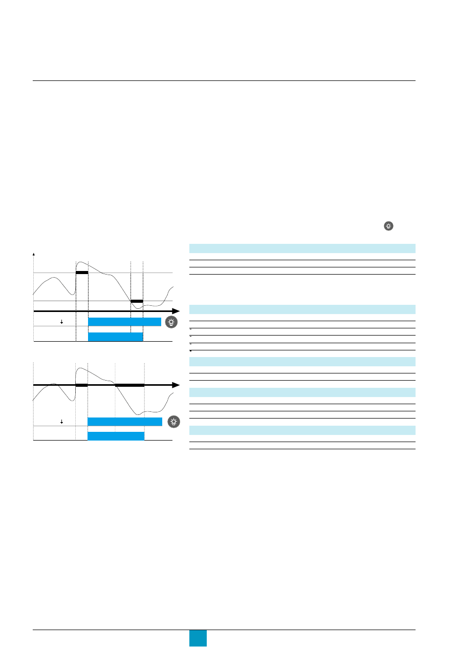
E71744A
E71745A
Different pickup and dropout thresholds
Identical pickup and dropout thresholds
I
I
I
I
Dropout
Other alarms
T1
T2
Pickup
Ir, Isd, Ii, I alarms
Pickup /
Dropout
Other alarms
T1
T2
Ir, Isd, Ii, I alarms
Micrologic P
Schneider Electric
25
An alarm is issued if the Alarm or the
Trip + Alarm mode was set for the given
protection function.
Caution!
The M2C and M6C contacts require an
auxiliary power supply. See the "Power
supply" section in the technical appendix.
Optional M2C and M6C contacts
E60492A
E60491A
c
current protection:
v
Ir
v
Isd
v
Ii
v
I
t
v
I
t
Alarm
v
I unbal
v
1 max
v
2 max
v
3 max
v
N max.
c
voltage protection:
v
U min
v
U max
v
U unbal.
c
other protection:
v
F min
v
F max
v
rP max
v
phase rotation.
c
available types of contacts:
v
M2C: up to two contacts maximum, S1 and S2
v
M6C: up to six contacts maximum, S1 to S6.
M2C and M6C contacts may not be used together.
c
load shedding and reconnection:
v
current I
v
power P.
c
latching settings:
v
non-latching contact: the contact remains activated as long as the fault that
caused the alarm has not been cleared
v
latching contact: the contact remains activated until it is reset ("Reset menu")
v
time-delay contact: the contact remains activated for the duration of an adjustable
time delay or until it is reset ("Reset menu"). The time-delay settings for time-delay
latching are provided in the technical appendix.
v
locked to 1: the contact is forced to 1 for an automation test
v
locked to 0: the contact is forced to 0 for an automation test.
c
contact operating diagram
v
different pickup and dropout thresholds
471
S1
474
484
S2
474
S1
3
1
5
4
2
6
S3
S2
9
7
11
10
8
12
S4
24V 0V
19
17
21
23
25
S5
14
16
18
S6
20
22
24
Com
Q1 Q2 Q3
Wiring diagram for M2C contacts.
Wiring diagram for M6C contacts
I
I
I
I
E71747A
E71746A
v
identical pickup and dropout thresholds
Pickup /
Dropout
Other alarms
Non-latching contact
Latching contact
Reset
possible
Time-delay contact
1 to 360 seconds
Reset possible
T1
T2
Ir, Isd, Ii, I alarms
Dropout
Other alarms
Non-latching contact
Latching contact
Reset
possible
Time-delay contact
1 to 360 seconds
Reset possible
T1
T2
Pickup
Ir, Isd, Ii, I alarms

Micrologic P
Schneider Electric
26
Overview of functions
Trip history
c
the trip history is the means to display at any time the parameters measured
during the last ten trips.
c
for each trip, the following parameters are recorded:
v
tripping cause
v
trip threshold
v
interrupted currents in amperes (only if an external power supply is present) for Ir,
Isd/Ii, Ig or IDn trips
v
date (only if an external power supply is present)
v
time (hours, minutes and seconds; only if an external power supply is present).
Alarm history
c
the alarm history is the means to display at any time the parameters measured
during the last ten alarms.
c
for each alarm, the following parameters are recorded:
v
alarm cause
v
alarm threshold
v
date (only if an external power supply is present)
v
time (hours, minutes and seconds; only if an external power supply is present).
Operation counter
This function is available only via the COM communications option.
c
Micrologic P:
v
stores and displays the total number of operations (incremented each time the
circuit breaker opens) since the initial installation of the circuit breaker
v
stores and displays the total number of operations since the last reset.
Contact wear indication
This function can be used to:
c
determine the condition of the most worn contact in the circuit breaker. A counter
is displayed on the screen. The contacts must be inspected each time the counter
reaches a hundred mark. The message "Not available or circuit breaker type not
defined" is displayed if the type of circuit breaker has not been defined. In this case,
see "Breaker selection" in the "Micrologic setup" menu under "History, maintenance
and setup".
c
reset the indicator after changing the main contacts. Reset is also carried out via
"Breaker selection" in the "Micrologic setup" menu.
Note:
If the control unit is changed, the circuit breaker must be defined again. In this case, see
"Breaker selection" in the "Micrologic setup" menu under "History, maintenance and
setup".
Event histories
Micrologic P
Schneider Electric
27
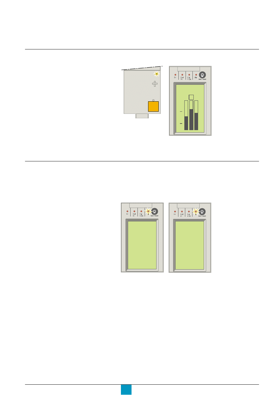
LED indicator
LEDs and display screens
The procedure required to reclose the
circuit breaker following a fault trip is
presented in the circuit-breaker user guide.
Signals overrun of the
long-time current setting
(1.125 x Ir).
Signals the load level on
each phase (0% x Ir,
50% x Ir, 100% x Ir).
E60444A
Overload bargraph on
the main screen
off
Alarm
E60495A
Micrologic 5.0 P
4260A
N 1 2 3
100
50
0
Fault-trip indications
c
control-unit status
The circuit breaker has tripped.
The display depends on whether the control unit is equipped with an external
power supply.
If an external power supply is not available
and the circuit breaker is closed, the
system displays the main screen.
Concerning the presence or absence of an
external power supply, see the "Power
supply" section in the technical appendix.
Caution!
The battery maintains the trip indications.
If no indications are displayed, check the
battery.
v
control unit without an
external power supply
v
control unit with an
external power supply
E60298A
Micrologic 5.0 P
E71600A
Micrologic 5.0 P
Trip
02:04:04
22/11/1999
Umin 100V
A LED signals the type of
fault (Ir, Isd, Ii, Ig, I
∆
n or
Ap).
The type of fault is
signalled by a LED and
on the graphic display.
Micrologic P
Schneider Electric
28
The self-protection function (excessive
temperature or short-circuit greater than
device capability) trips the circuit breaker
and turns the Ap LED ON.
A number of simultaneous causes may
result in tripping. For example, a short-
circuit and a distribution-system voltage
under a set value.
The LED signalling the last fault
chronologically is the only one to remain
ON. E.g., the Ap LED may signal a voltage
drop under a set value where the voltage
drop was caused by a short-circuit.
c
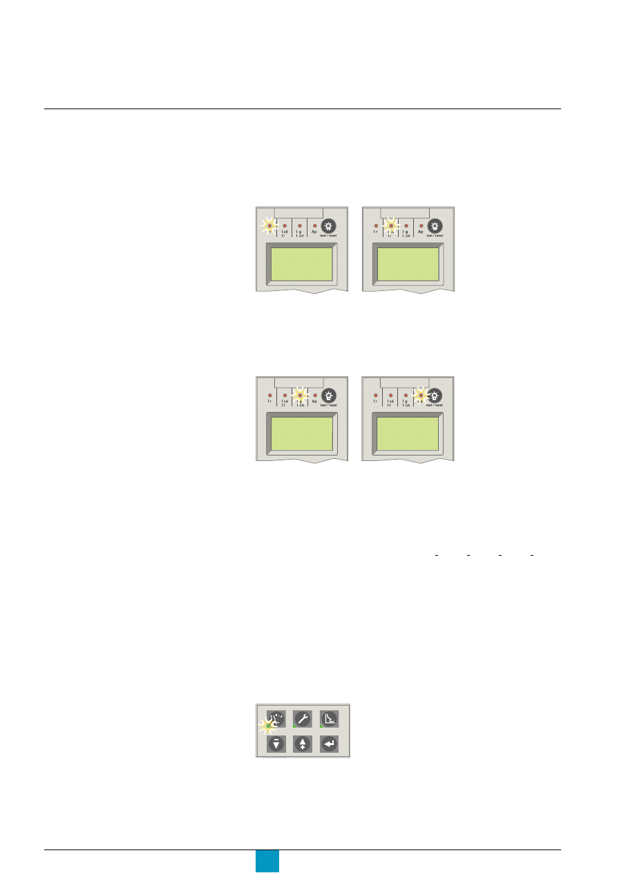
fault-trip LEDs
c
the LEDs indicate the type of fault that tripped the circuit breaker
c
the LEDs are located in the upper part of the front panel (red Ir, Isd, Ii, Ig, I
2
n and
Ap LEDs)
c
when activated, a LED automatically goes ON and remains ON until it is locally
reset.
E60337A
E60338A
Signals tripping following
overrun of the long-time
current setting Ir.
Signals tripping following
overrun of the short-time
pickup Isd or the
instantaneous pickup Ii.
c
Ir LED
c
Isd, Ii LED
c
Ig, I
∆
n LED
c
Ap LED
E60339A
E60340A
Signals tripping following
overrun of the earth-fault
pickup Ig or the earth-
leakage pickup I
∆
n.
Signals tripping due to:
c
self-protection function:
v
temperature
v
ASIC power supply
v
instantaneous pickup for circuit-breaker self
protection
c
protection functions:
v
current unbalance I unbal
v
maximum current 1 max, 2 max, 3 max, N max;
v
voltage unbalance U unbal
v
maximum voltage U max
v
minimum voltage U min
v
reverse power rP max
v
maximum frequency F max
v
minimum frequency F min
v
phase rotation.
I
I
I
I
LEDs and display screens
Overview of functions
c
LEDs on buttons to access the menus
The activated LED indicates the menu for which the screen is displayed:
v
"Metering"
v
"History, maintenance and setup"
v
"Protection".
E60485A
Micrologic P
Schneider Electric
29
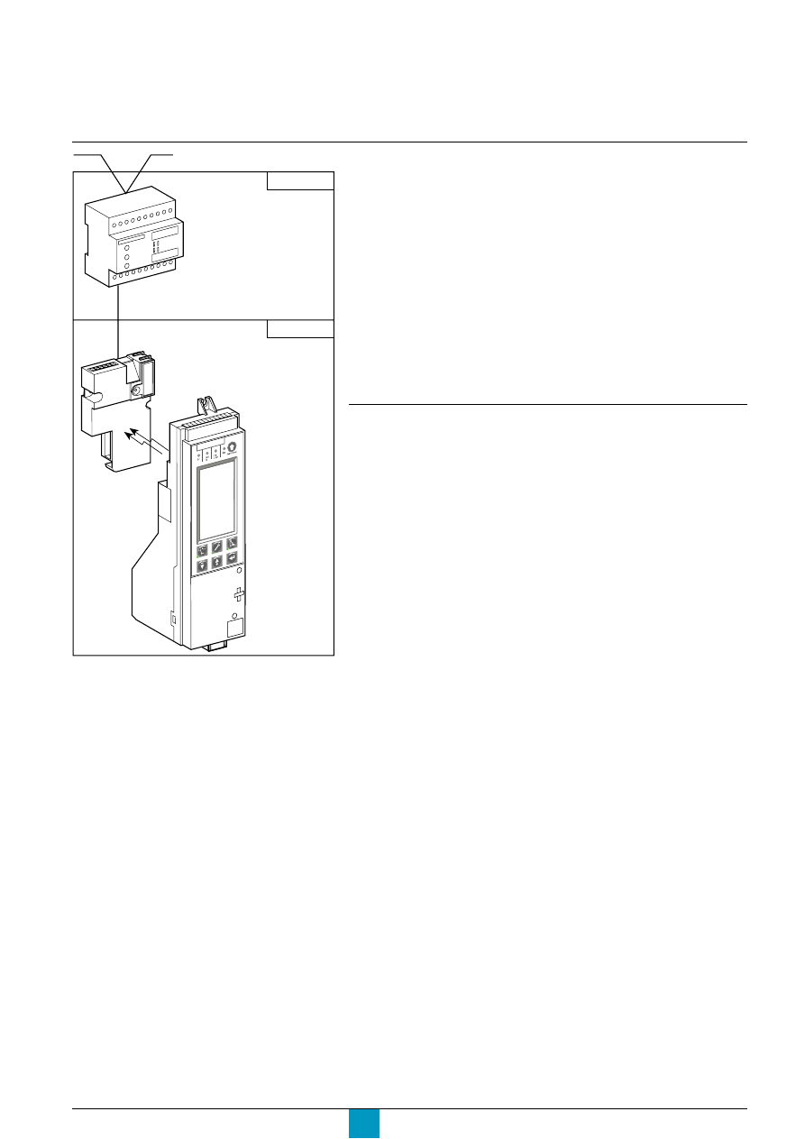
Micro
logic
5.0 P
COM module on
chassis (optional)
COM module on circuit breaker
(Infra Red)
Micrologic P
control unit
Circuit breaker
Chassis
COM communications option
E71748A
Communication options
Digipact and ModBus are the indispensable elements when integrating Micrologic
P in the Digivision and SMS Powerlogic installation-management systems which
communicate via the BatiBus and ModBus protocols.
External gateways are available for communication over other networks, including
ProxiBus, Ethernet, etc.
The communications option makes possible the following remote functions:
c
device identification:
v
address
v
device type
v
control-unit type
v
type of long-time rating plug
c
settings:
v
reading of the dial settings
v
fine adjustments within the range determined by the dial
v
protection and alarm settings.
Operating and maintenance aids
c
protection and alarm values:
v
standard
v
set.
c
measurement values:
v
currents
v
voltages, frequencies, power, etc.
c
fault values:
v
fault type
v
interrupted current.
c
histories and logs:
v
trip history
v
alarm history
v
event history.
c
indicators:
v
contact wear, counters, etc.
v
maintenance register.
Micrologic P
Schneider Electric
30
Setup
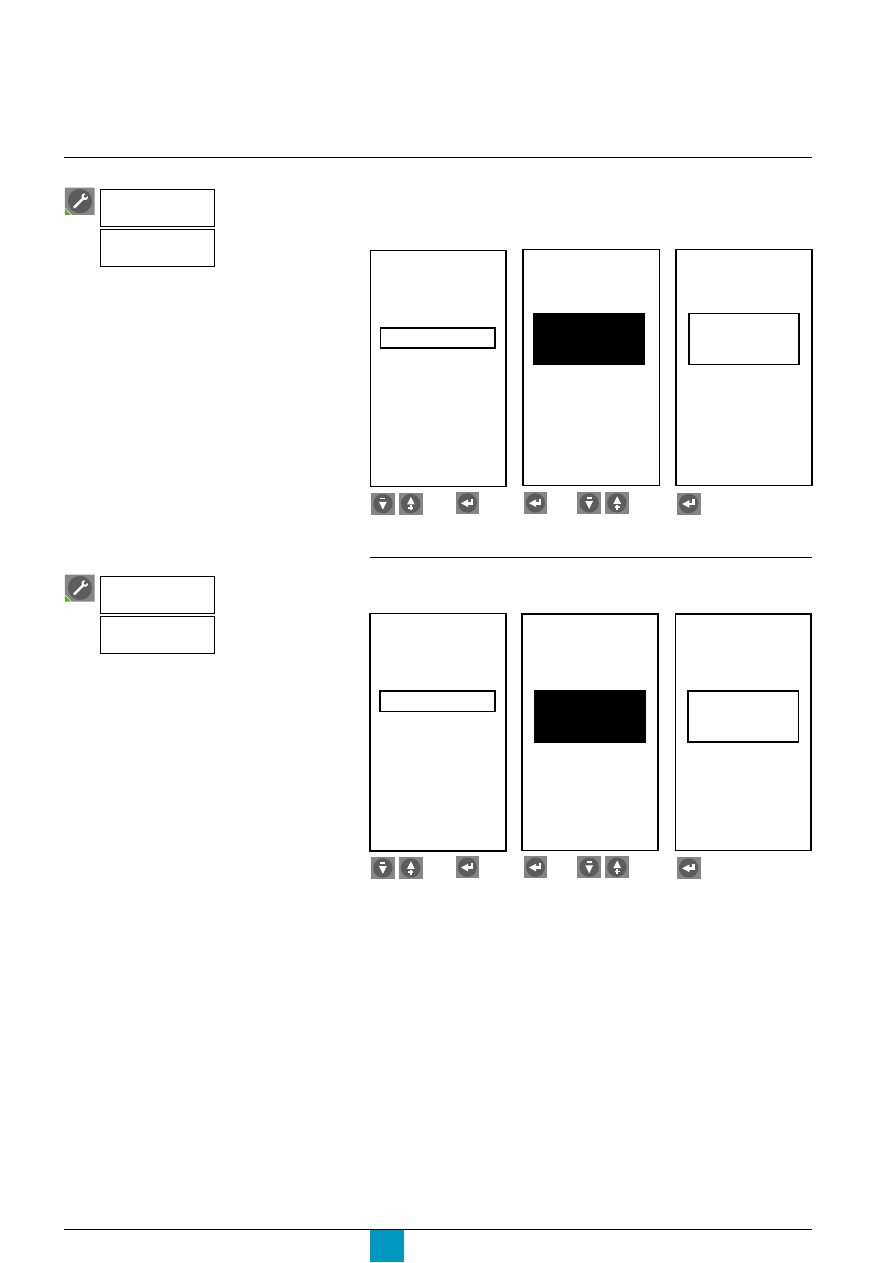
Select an alarm
Note:
An alarm may be selected if the "Alarm" or "Trip + Alarm" mode was selected during setup of
the given protection function, in the "Protection" menu.
Set up each contact
c
select the latching mode
Select the command
Setting up the optional
M2C / M6C contacts
Select the command
E71601A
S1
S2
Alarm
type
E60146A
S2
Ir
E60226A
S2
Ir
E71602A
E71603A
E71604A
S1
S2
Setup
M2C / M6C
S2
latching
contact
Mode
S2
Mode
latching
contact
Contacts
M2C / M6C
Alarm
type
Contacts
M2C / M6C
Setup
then
then
Select a contact.
Select an alarm.
Confirm.
then
then
Select a contact.
Select a latching mode.
Confirm.
Micrologic P
Schneider Electric
31
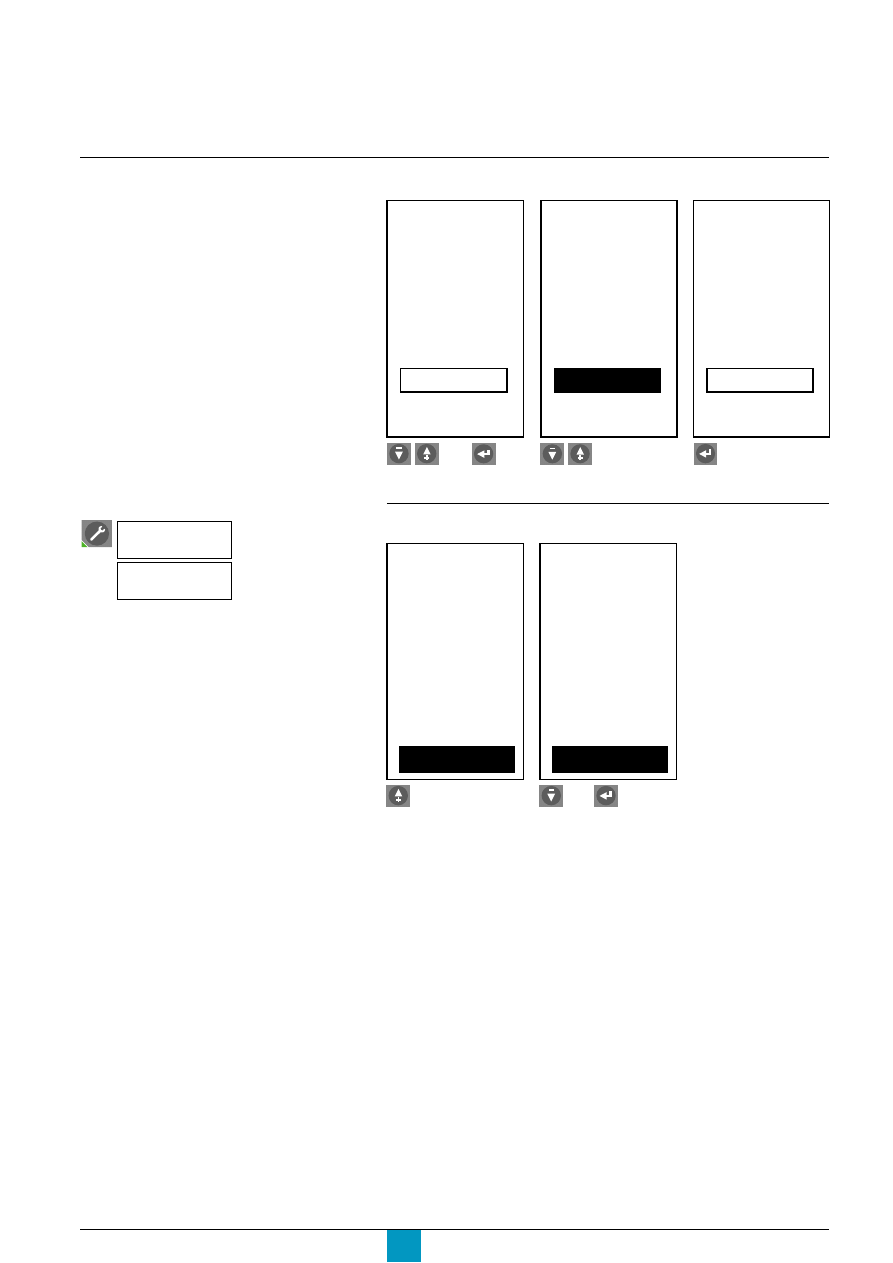
c
set the time delay for time-delay latching
Reset the contacts to 0
E71605A
360s
time delay
S2
Mode
Delay
E71606A
350s
time delay
S2
Mode
Delay
E71607A
350s
time delay
S2
Mode
Delay
E60442A
E60389A
S1 0
M2C / M6C
Reset (- / +)
S2 0
S1 1
M2C / M6C
Reset (- / +)
S2 1
Reset the contacts to 0…
or cancel the reset,
then confirm.
Select the command
M2C / M6C
Contacts
Reset
then
Select the time delay.
Adjust.
Confirm.
then
Micrologic P
Schneider Electric
32
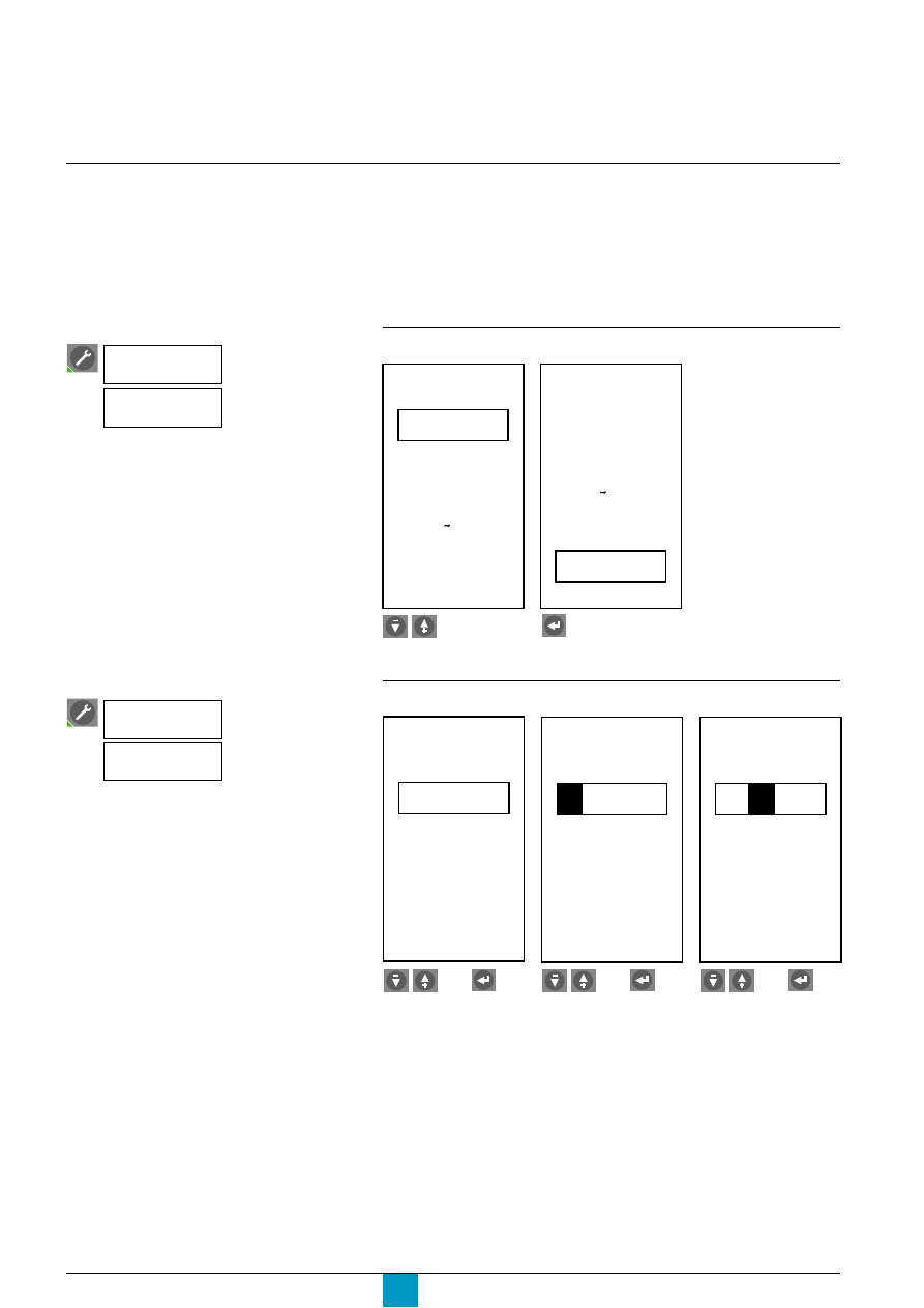
Setup
Set the date and time
Setting up the Micrologic
control unit
E71608A
Language
Deutsch
English US
English UK
Espanol
Français
E71609A
Language
English US
English UK
Espanol
Français
Italiano
E71610A
E71611A
E71612A
Hour
Date
01 / 01 / 2000
18 : 30 : 03
Hour
Date
01
/ 01 / 2000
18 : 30 : 03
Hour
Date
01 /
01
/ 2000
18 : 30 : 03
Select the date.
Enter the day.
Enter the month.
Caution!
If the date and time are not displayed, see
the "Power supply" section in the technical
appendix.
Enter the date and time for time-stamping
purposes in the trip and alarm histories.
The resolution of the time setting is 20 ms.
If the time is set via a communications
module, any previous manual setting is
automatically erased.
If the time value is not synchronised by a
supervisor via the communications option,
the maximum possible drift is one hour per
year.
Prior to setting up the protection functions or carrying out measurements,
the following operations are required:
c
selection of the display language
c
entry of the date and time
c
entry of the circuit-breaker type
c
entry of the neutral current-transformer type
c
selection of the transformation ratio between the primary and secondary windings
if an auxiliary voltage transformer is installed
c
entry of the rated frequency.
Select the display language
Select the command
Micrologic
setup
Language
Select the command
Micrologic
setup
Date / hour
Select.
Confirm.
then
then
then
Micrologic P
Schneider Electric
33
E71615A
E71616A
NT08N
Circuit breaker
Standard
0 3 E 7
type
v=07.002
Breaker
selection
Masterpact
UL
NT H1
selection
Circuit breaker
Standard
0 3 E 7
type
v=07.002
Breaker
Masterpact
IEC
E71617A
NT H1
Circuit breaker
Standard
0 3 E 7
type
v=07.002
Breaker
selection
Masterpact
IEC
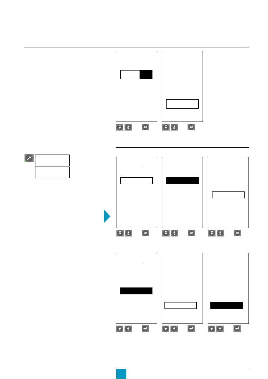
The circuit-breaker code is required to
identify the device and activate the contact-
wear counter.
Note this code if the control unit
must be changed (example 03E7).
Enter this code when setting up a new
control unit on the circuit breaker.
When the main circuit-breaker contacts are
replaced, this code must be reset to zero.
Circuit-breaker selection
E71618A
E71619A
E71620A
630b
Circuit breaker
Standard
0 3 E 7
type
v=07.002
Breaker
selection
Compact NS
IEC
630b
Circuit breaker
Standard
0 3 E 7
type
v=07.002
Breaker
selection
Compact NS
IEC
800
Circuit breaker
Standard
0 3 E 7
type
v=07.002
Breaker
selection
Compact NS
IEC
Choose and confirm.
Select the type.
Choose and confirm.
E71613A
E71614A
Enter the year.
Set the time in the same
manner.
Hour
Date
01 / 01 /
2000
18 : 30 : 03
Hour
Date
01 / 01 /
2000
18 : 30 : 03
Select the command
Micrologic
setup
Breaker
selection
then
then
then
then
then
then
then
then
Select the standard.
Choose and confirm.
Select the circuit breaker.
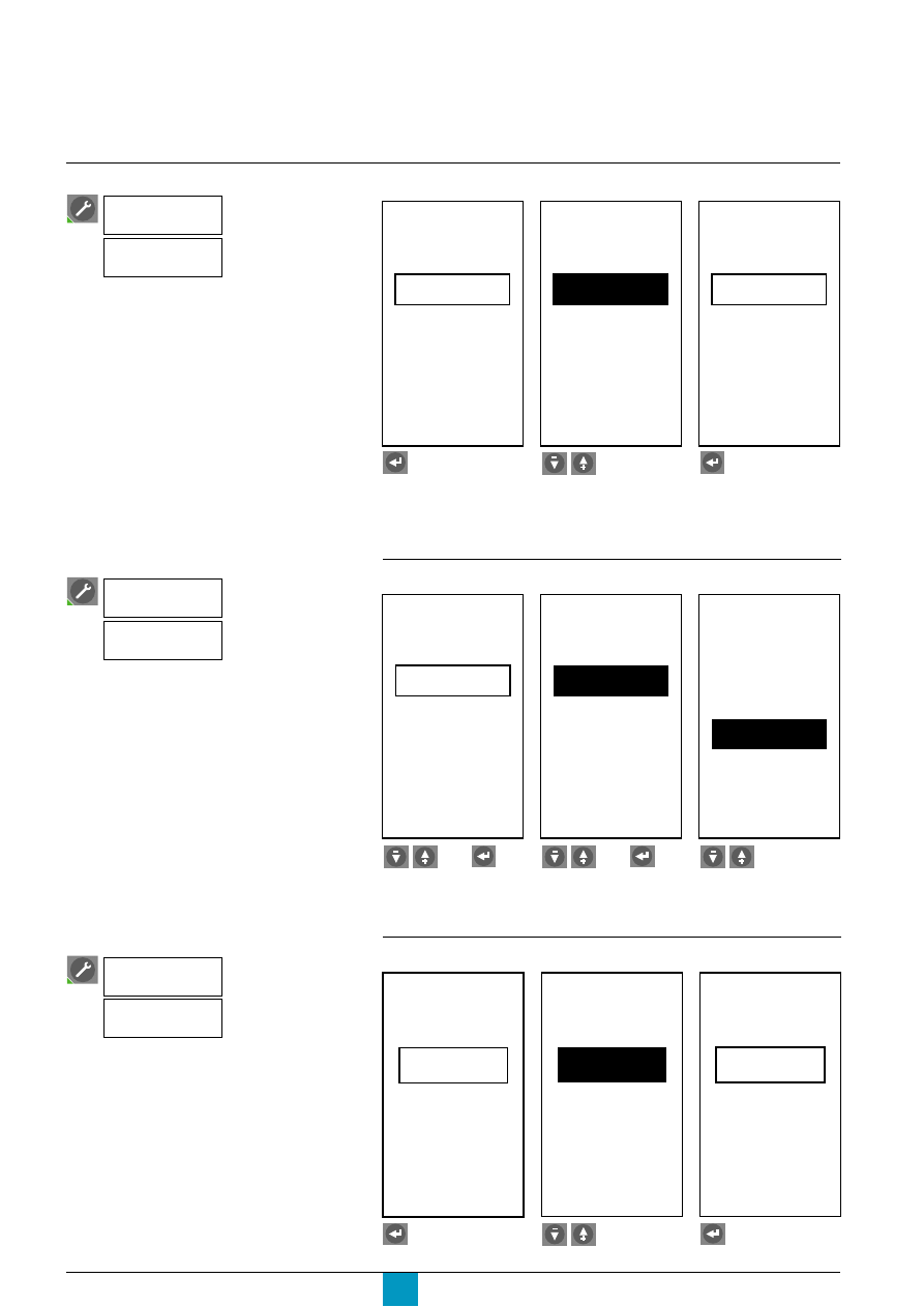
Micrologic P
Schneider Electric
34
Setup
Setting up the Micrologic
control unit
If the supply voltage for the control unit
exceeds 690 V, an external voltage
transformer must be installed.
To display the true voltage values, enter the
transformation ratio between the primary
and secondary voltages of the transformer.
Note that if Digipact display modules are
used, the rated distribution-system voltage
must be entered.
Enter the voltage-transformation ratio
E71624A
E71625A
E71626A
Secondary
Primary
VT ratio
690V
690V
Secondary
Primary
VT ratio
690V
690V
Secondary
Primary
VT ratio
690V
690V
Select either the:
c
primary voltage
c
secondary voltage.
Enter the voltage.
Go on to the next setting.
Enter the rated frequency
E71627A
E71628A
E71629A
System
frequency
400Hz
System
frequency
50 - 60Hz
System
frequency
50 - 60Hz
Select the neutral-CT type
E71621A
E71622A
E71623A
none
Neutral CT
Internal
Neutral CT
Internal
Neutral CT
Press enter.
Choose between
c
none
c
internal
c
external.
Confirm.
Select the command
Micrologic
setup
Neutral CT
Select the command
Micrologic
setup
VT ratio
Select the command
Micrologic
setup
System
frequency
Phase rotation is the only protection
function deactivated when a frequency of
400 Hz is selected.
Press enter.
Choose.
Confirm.
then
then
If the "none" option is selected, the neutral
current is not displayed.
Caution!
On a four-pole circuit breaker, the "Internal"
option must be selected to eliminate the
2xN setting for the neutral.
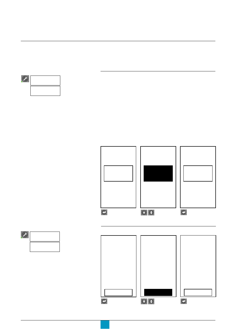
Micrologic P
Schneider Electric
35
Caution!
The neutral current IN cannot be measured
with the "3-phase, 3-wire, 3-CT" and
"3-phase, 4-wire, 3-CT" types.
To measure the neutral current, select
"3-phase, 4-wire, 4-CT" and connect the
neutral (using a voltage-measurement input
if necessary).
See the "Overview of functions" section for
information on the available types of
measurements.
Setting up the metering functions
Prior to setting up the protection functions or carrying out measurements,
the following operations are required:
c
entry of the system type
c
selection of the calculation mode for the demand current
c
selection of the calculation mode for the demand power
c
selection of the sign convention for the active power P.
Select the system type
The Micrologic P control unit offers three measurement options:
c
3 phases, 3 wires, 3 CTs: method using two wattmeters:
v
measurement of phase-to-neutral voltages (rms, unbalance and average values
disabled), power measurements (P, Q and S) and power factor per phase disabled
v
measurement of I1, I2 and I3
v
IN disabled (rms, demand)
c
3 phases, 4 wires, 4 CTs: method using three wattmeters:
measurement of I1, I2, I3 and IN
c
3 phases, 4 wires, 3 CTs: method using three wattmeters:
v
system with neutral
v
measurement of I1, I2 and I3
v
IN disabled (rms, demand).
Note:
It is advised not to use the "3-phase, 4-wire, 4-CT" type of measurement unless the neutral is
effectively connected to the control unit (four-pole circuit breaker with an external voltage-
measurement input).
E71630A
E71631A
E71632A
Press enter.
Choose.
Confirm.
3
Φ
4w
3CT
System
type
3
Φ
3w
3CT
System
type
3
Φ
3w
3CT
System
type
Select the time interval for calculation of the demand current
E71633A
E71634A
E71635A
Press enter.
Adjust.
Confirm.
Sliding
window
Current
demand
Interval
30 min
Sliding
window
Current
demand
Interval
40 min
40 min
Sliding
window
Current
demand
Interval
Select the command
Metering
setup
System
type
Select the command
Metering
setup
Current
demand
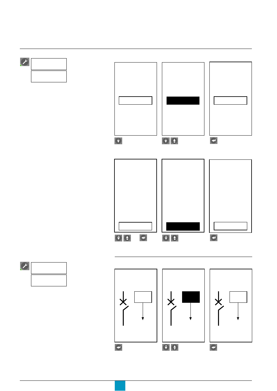
Micrologic P
Schneider Electric
36
Setup
Setting up the metering functions
By default, Micrologic P uses P+ for the
power flowing from top to bottom terminals.
The selected direction of flow is valid for:
c
measurement of power and the power
factor
c
measurement of energy
c
load shedding and reconnection
depending on power.
Select the calculation mode for the demand power
E71636A
E71637A
E71638A
Select the existing
window type.
Choose either the sliding
or block window.
Confirm.
Window type
Interval
10 min
Power
demand
sliding
Window type
Interval
Power
demand
10 min
block
Window type
Interval
Power
demand
10 min
block
E71639A
E71640A
E71641A
Select the existing
interval.
Adjust.
Confirm.
Window type
Interval
Power
demand
10 min
block
Window type
Interval
Power
demand
13 min
block
Window type
Interval
Power
demand
13 min
block
Select the sign convention for the active power
E71642A
E71643A
E71644A
Press enter.
Choose.
Confirm.
ActiveP
flow
P
-
ActiveP
flow
P
+
ActiveP
flow
P
+
Select the command
Metering
setup
Power
demand
Select the command
Metering
setup
Active P
flow
then
If the settings are changed, any previously
stored measurements are erased.
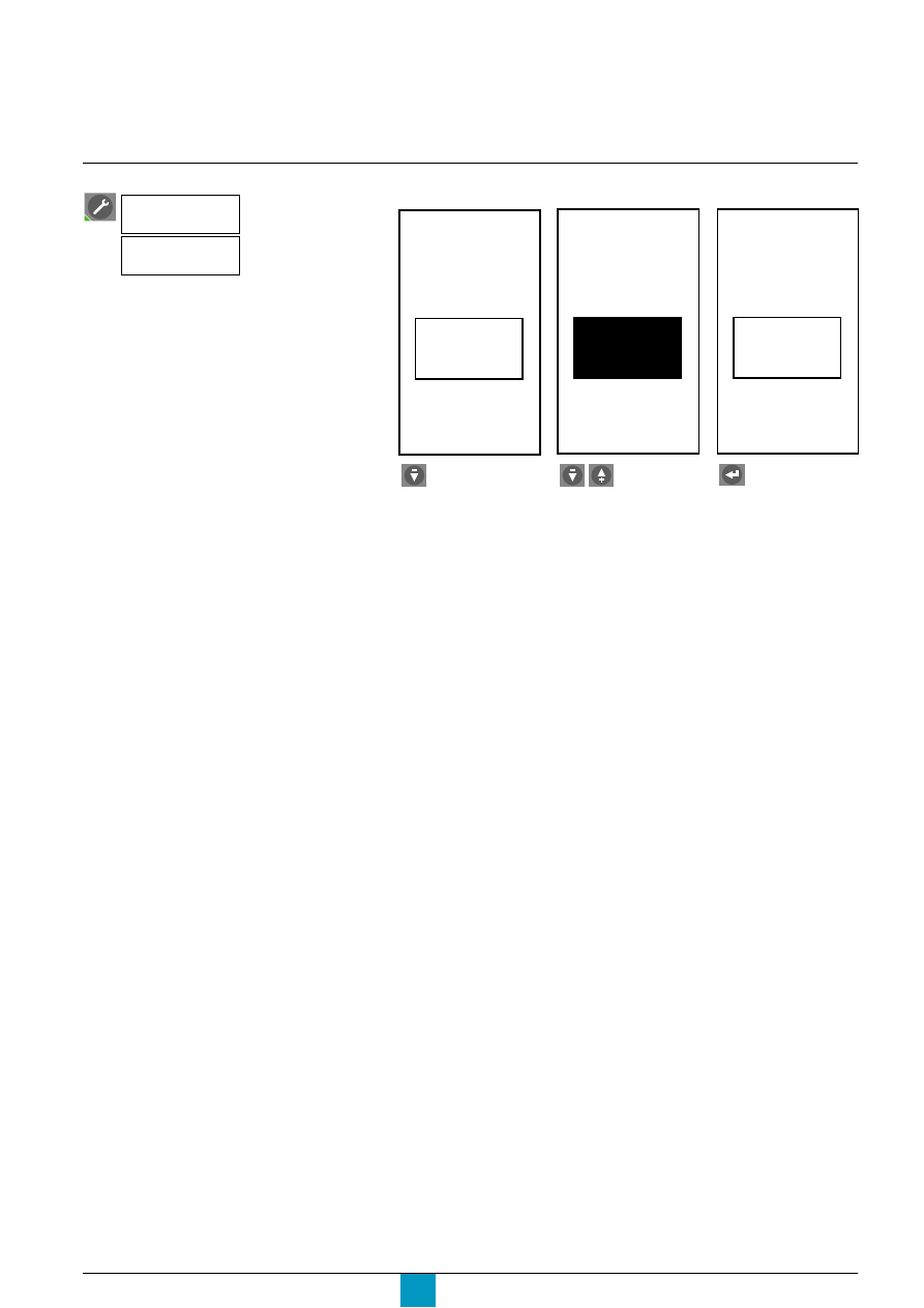
Micrologic P
Schneider Electric
37
Select the command
Metering
setup
Sign
convention
Set up the power-factor calculation
E71646A
E71647A
Press enter.
Choose between IEEE,
IEEE alternate or IEC.
Confirm.
IEEE
Sign
convention
E71645A
IEEE alt.
Sign
convention
IEEE alt.
Sign
convention
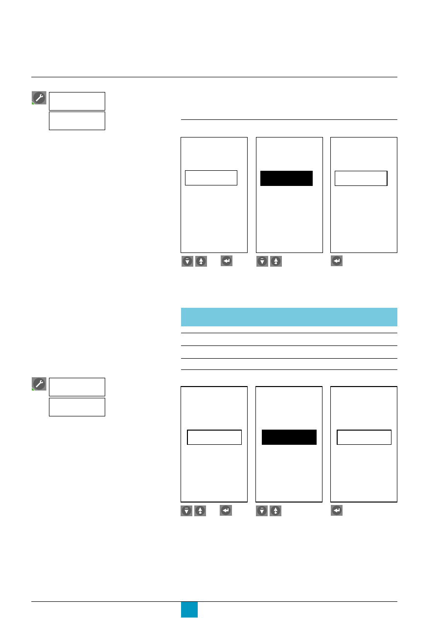
Micrologic P
Schneider Electric
38
Setup
As soon as the BBus or ModBus
communications option is connected, the
control unit recognises it and displays the
type of module on the graphic screen.
Automatic time updates are possible only
with the ModBus system.
Setting up the COM
communications option
When a COM communications option is used, it is necessary to:
c
set up the COM communications option
c
authorise remote setting of the Micrologic control unit
c
authorise remote control of the circuit breaker.
View and set up the communications option
E71723A
E71724A
E71725A
Select an existing
parameter.
Adjust.
Confirm.
47
Baud-rate
Parity
9600
None
Modbus
Com
Address
Modbus
Com
Parity
9600
None
45
Baud-rate
Address
Parity
9600
None
Modbus
Com
Address
45
Baud-rate
Adjust all the other parameters for the communications option in the same manner.
B BUS
MODBUS
(read only)
(read and set up)
Address
1 - 255
1 - 47
Baud rate
9 600 bauds
19 200 bauds
Parity
Even
None
Authorise remote setup of Micrologic
E71726A
E71727A
E71728A
Select existing setting.
Choose.
Confirm.
No
Access
code
0 0 0 0
Remote
settings
Access
permit
Access
code
Remote
settings
Access
permit
Yes
0 0 0 0
Access
code
Remote
settings
Access
permit
Yes
0 0 0 0
Select the command
Com.
setup
Com.
parameter
then
Select the command
Com.
setup
Remote
settings
then
The access code is a password that must
be provided by the supervisor prior to
accessing the Micrologic settings.
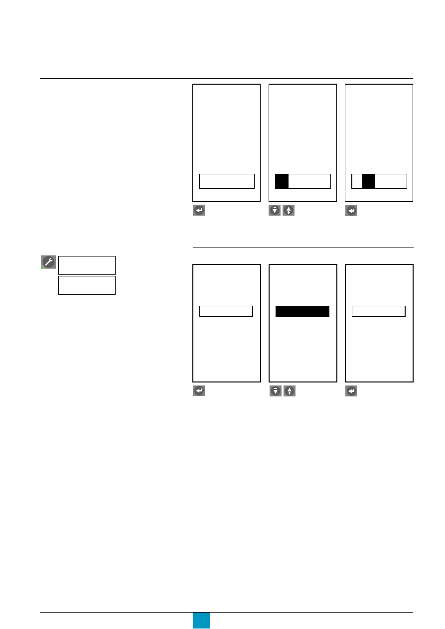
Micrologic P
Schneider Electric
39
Circuit-breaker control may be locked in
local mode (Manual) or remote mode
(Auto).
E71729A
E71730A
E71731A
Select the existing
access code setting.
Enter the first digit.
Confirm and proceed in
the same manner for the
other digits.
Authorise remote control of the circuit breaker
E71732A
E71733A
E71734A
Press enter.
Select Auto or Manual.
Confirm.
Access
code
Remote
settings
Access
permit
Yes
0 0 0 0
Access
code
Remote
settings
Access
permit
Yes
1
0 0 0
Access
code
Remote
settings
Access
permit
Yes
1
0
0 0
Manual
Remote
control
Auto
Remote
control
Auto
Remote
control
Select the command
Com.
setup
Remote
control
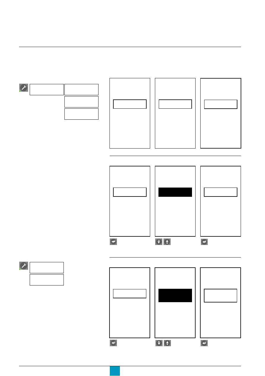
Micrologic P
Schneider Electric
40
Setting up the protection
functions
Prior to setting up the protection functions, the following operations are required:
c
set up the alarm mode alone or the alarm with tripping for the:
v
current protection
v
voltage protection
v
other protection
c
select the normal direction of power flow.
Select the direction.
Selection of the normal direction of power
flow makes it possible to define the sign
convention used for the reverse power rP
protection function.
Select one of the two directions:
v
"Top fed" corresponds to the normal flow
from the top terminals to the bottom
terminals
v
"Bottom fed" corresponds to the reverse
direction of flow.
E71648A
E71649A
E71650A
Select the operating mode
E71651A
E71652A
E71653A
Press enter.
Select the operating
mode.
Current
protection
Mode
Alarm
Mode
Alarm
Voltage
protection
Other
protection
Mode
Alarm
Mode
Alarm
Current
protection
Mode
Trip
Current
protection
Mode
Trip
Current
protection
Select the normal direction of power flow
E71654A
E71655A
E71656A
Press enter.
Power
flow
Convention
Top fed
Bottom
fed
Power
flow
Convention
Bottom
fed
Power
flow
Convention
Confirm.
Select the command
Protection
setup
Power
flow
Following detection of a fault by the:
c
current protection
c
voltage protection
c
other protection.
Micrologic P can implement two different
modes:
c
"Alarm" mode: an alarm may be selected
during setup of the current, voltage or other
protection functions
c
"Trip" (Trip + Alarm) mode: an alarm and
circuit-breaker tripping may be selected
during setup of the current, voltage or other
protection functions.
Protection
setup
Current
protection
Voltage
protection
Other
protection
Select the desired menu
Confirm.
Setup

Micrologic P
Schneider Electric
41
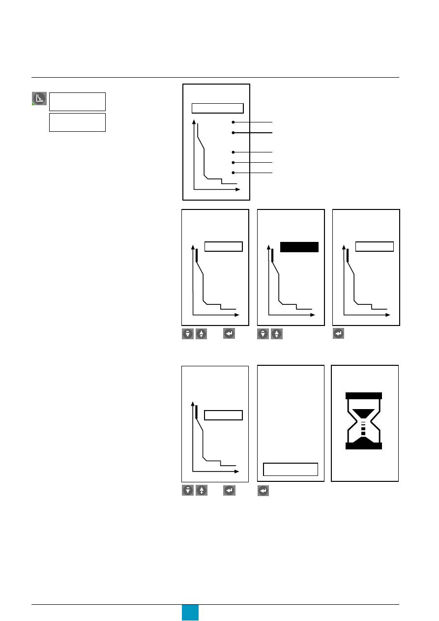
Micrologic P
Schneider Electric
42
Fine adjustment of the long-time
I
2
t, short-time and instantaneous
settings using the keypad
E71738A
E60275A
E60149A
E60276A
I
(A)
Trip
2000 A
0.2 s
4000 A
1.0 s
1000 A
I
(A)
Trip
2000 A
0.2 s
4000 A
1.0 s
998 A
I
(A)
Trip
2000 A
0.2 s
4000 A
1.0 s
998 A
Select a setting.
Adjust the value.
Confirm.
E60277A
Adjust the other settings
and confirm.
I
(A)
Trip
2000 A
0.2 s
4000 A
1.0 s
998 A
Select the command.
Current
protection
then
I
(A)
E60484A
E71657A
No
Yes
Do you want
to save new
settings?
then
Protection settings
When all the settings have been adjusted,
quit the screen by pressing one of the
menu-access buttons. This saves the new
values.
Confirm.
I
(A)
Trip
2000 A
0.2 s
4000 A
1.0 s
1000 A
long-time current setting Ir
long-time tripping delay tr
short-time tripping delay tsd
instantaneous pickup Ii
short-time pickup Isd
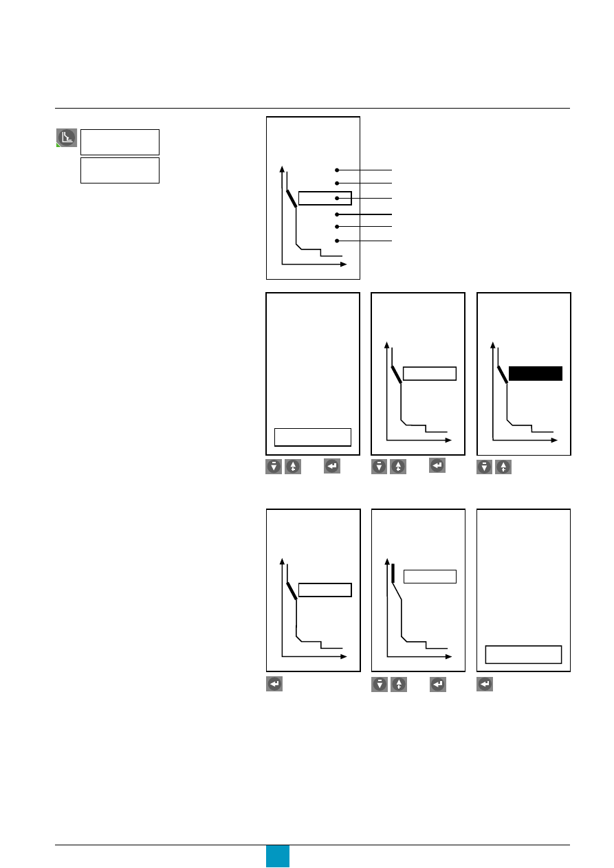
Micrologic P
Schneider Electric
43
Fine adjustment of the long-time
Idmtl, short-time and
instantaneous settings using
the keypad
E71739A
E71718A
E60278A
E60151A
Yes
I
dmtl
(A)
No
Change I(A)
settings with
Idmtl(A)?
I
dmtl (A)
Trip
2000 A
0.2 s
4000 A
1.0 s
1000 A
EIT
I
dmtl (A)
Trip
2000 A
0.2 s
4000 A
1.0 s
1000 A
VIT
Select yes.
Select a setting.
Change the setting.
E60279A
E60280A
E71657A
Confirm.
Adjust the other settings.
Confirm.
I
dmtl (A)
Trip
2000 A
0.2 s
4000 A
1.0 s
1000 A
VIT
I
dmtl (A)
Trip
2000 A
0.2 s
4000 A
1.0 s
1000 A
VIT
No
Yes
Do you want
to save new
settings?
Select the command
Current
protection
I
dmtl
(A)
then
then
puis
long-time current setting Ir
long-time tripping delay tr
short-time tripping delay tsd
instantaneous pickup Ii
short-time pickup Isd
Idmtl protection:
DT, SIT, VIT, EIT, HVF
I
dmtl (A)
Trip
2000 A
0.2 s
4000 A
1.0 s
1000 A
EIT
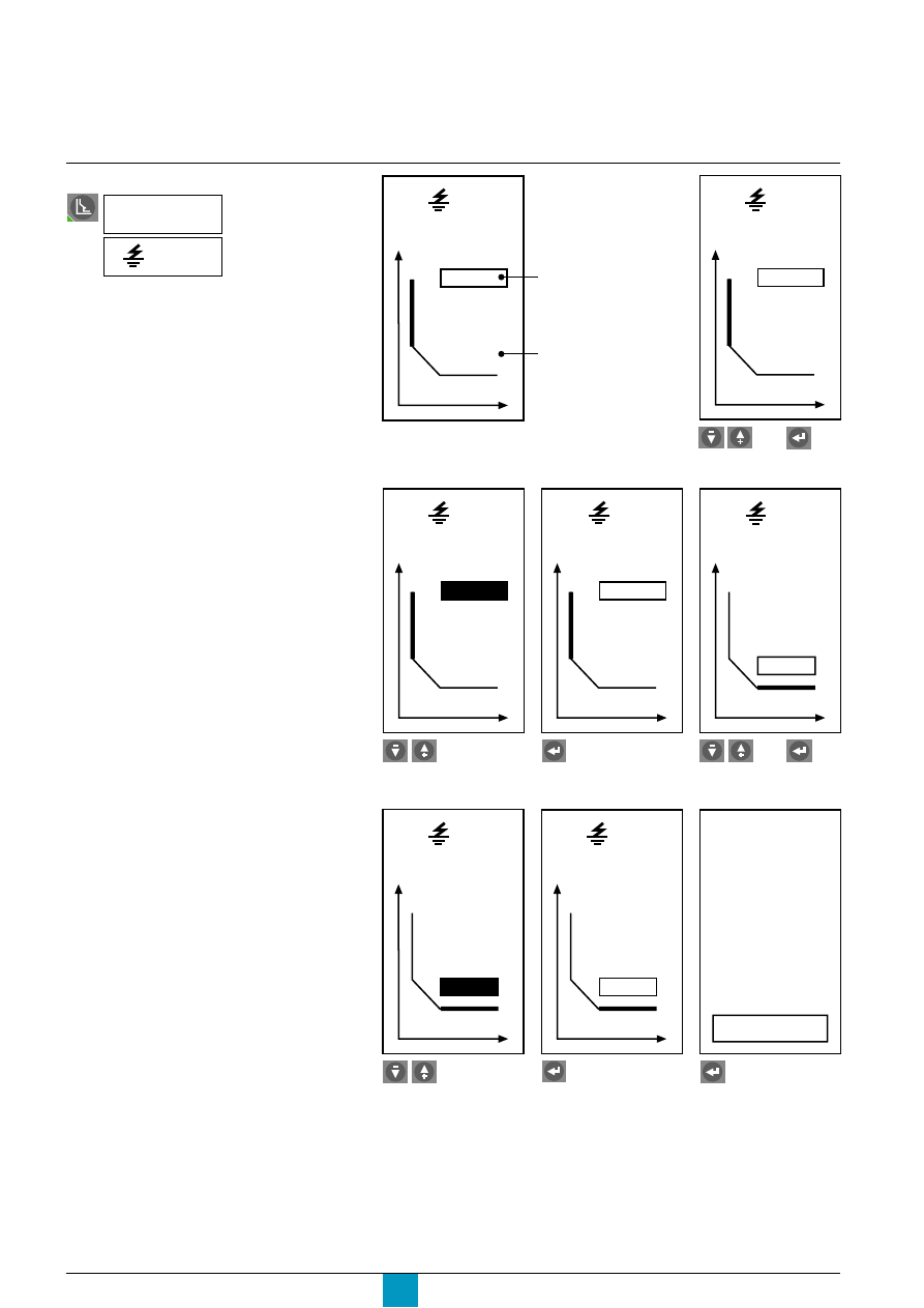
Micrologic P
Schneider Electric
44
Fine adjustment of the earth-fault
and earth-leakage protection
setting using the keypad
E71750A
E60282A
I
(A)
Trip
0.5s
1200A
Select a setting.
Adjust the value.
Confirm.
Go to the next setting.
E60283A
E60285A
E60284A
I
(A)
Trip
0.5s
1198A
I
(A)
Trip
0.5s
1198A
I
(A)
Trip
0.5s
1198A
Adjust the value.
Confirm.
Confirm to save
new settings.
E60286A
E71657A
E60287A
I
(A)
Trip
0.4s
1198A
I
(A)
Trip
0.4s
1198A
No
Yes
Do you want
to save new
settings?
Select the command
Current
protection
I
(A)
then
then
Protection settings
When all the settings have been adjusted,
quit the screen by pressing one of the
menu-access buttons. This saves the new
values.
I
(A)
time delay
Trip
0.5s
1200A
threshold
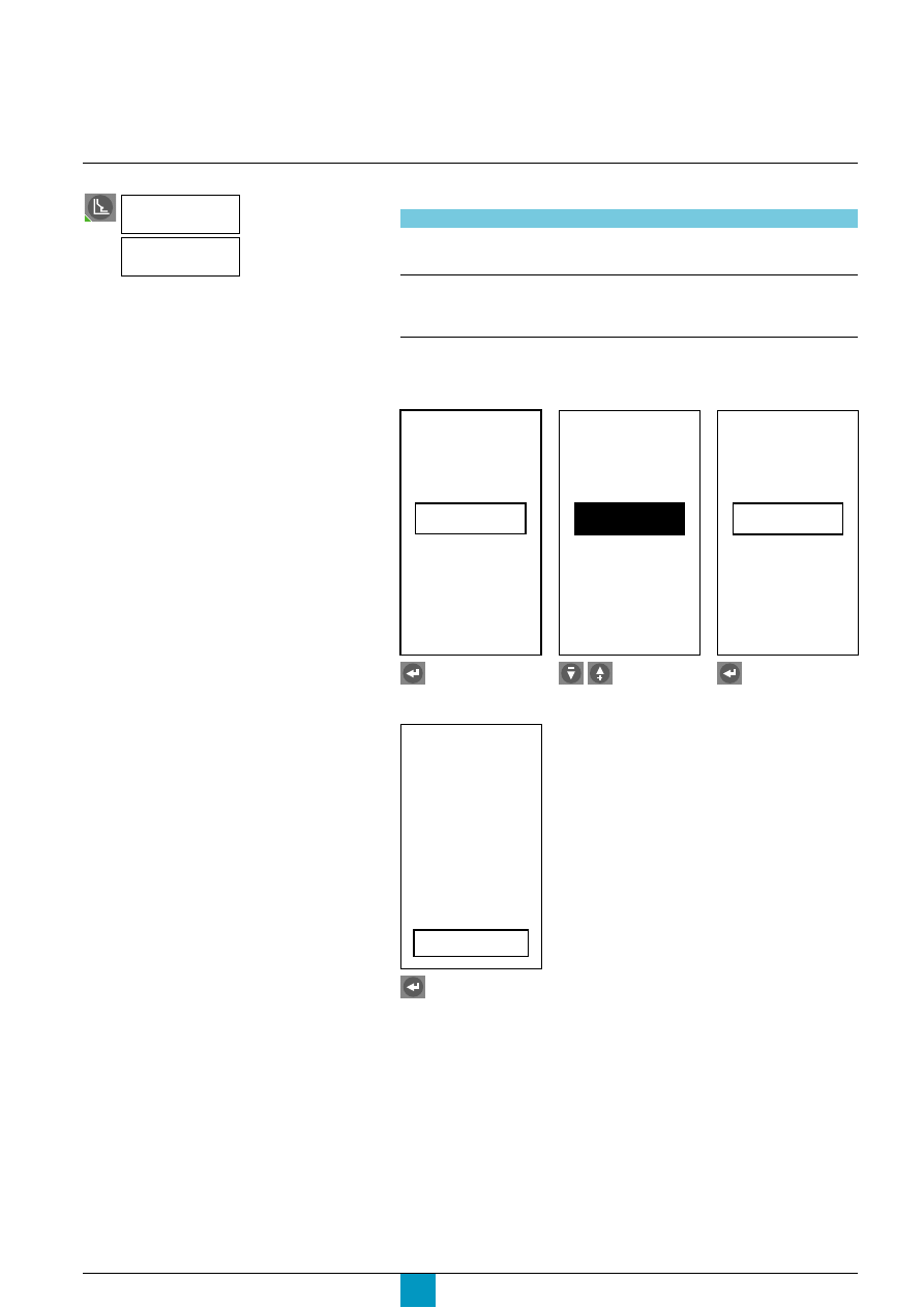
Micrologic P
Schneider Electric
45
Using the keypad on the control unit
Setting the neutral protection
E71658A
E71659A
E71660A
I
neutral (A)
OFF
I
neutral (A)
N / 2
I
neutral (A)
N / 2
Press enter.
Select the type of neutral
protection.
Confirm.
E71657A
No
Yes
Do you want
to save new
settings?
Confirm.
Type of circuit breaker
Possibles choices
four-pole
OFF: no neutral protection
N / 2: half neutral protection
N: full neutral protection
three-pole
OFF: no neutral protection
N / 2: half neutral protection
N: full neutral protection
N x 2: double neutral protection
Note:
On four-pole circuit breakers, setting of the neutral using the keypad is limited by the dial
setting.
Select the command
Current
protection
I
neutral (A)
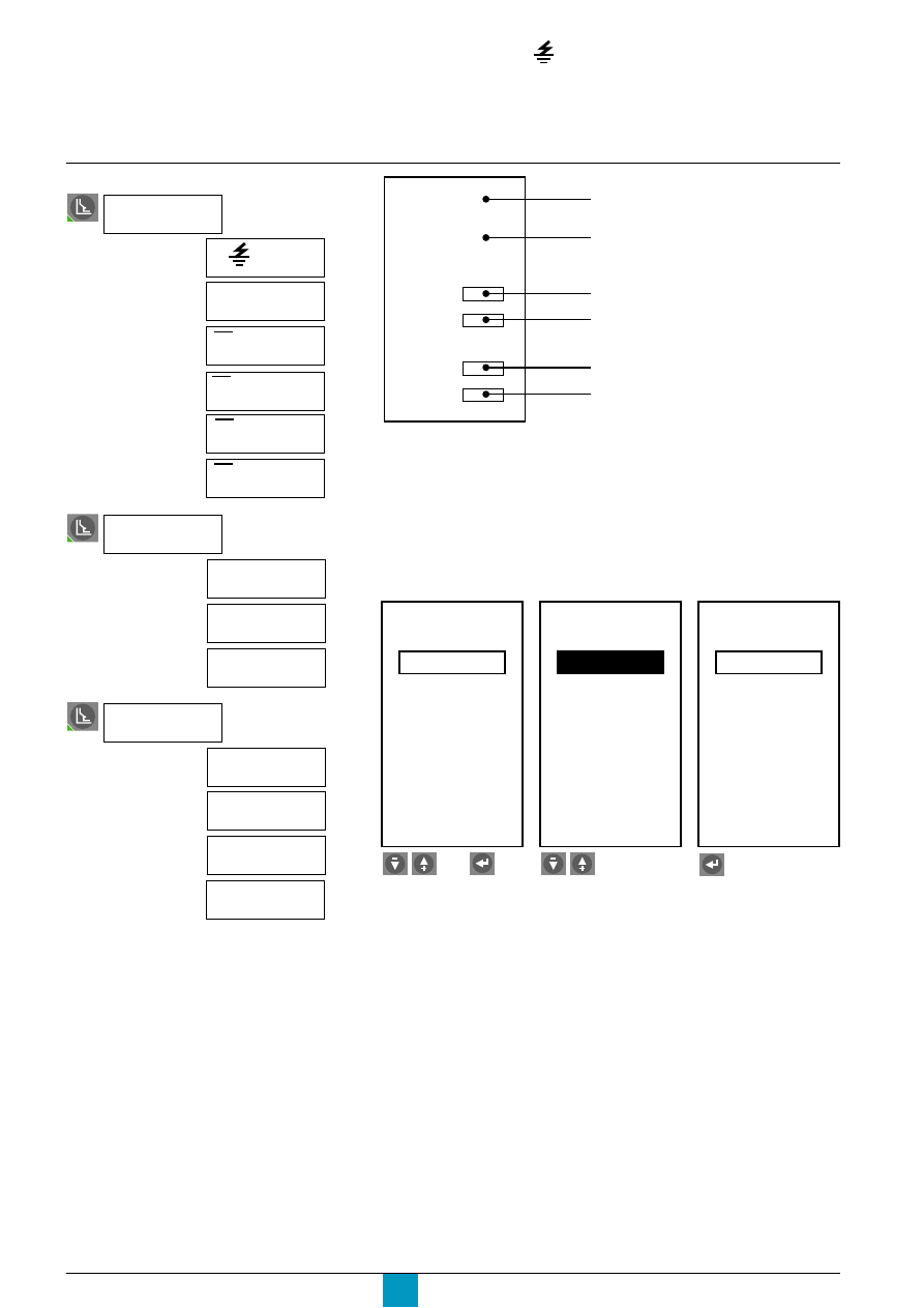
Micrologic P
Schneider Electric
46
Protection settings
Trip mode is available if the given protection function was set to trip mode in the
"Protection setup" menu under "History, maintenance and setup".
Specific case for I
t
alarm
Only the following choices are available:
c
On: activation of the alarm without fault tripping by the circuit breaker
c
Off: alarm disabled.
For example, take the U max setting.
Setting the I
, I unbal, max, U min,
U max, U unbal, rP max, F min,
F max, and phase-rotation protection
functions using the keypad
E71661A
E71662A
E71663A
E71664A
U
max
(V)
690V
Off
Pick up
Drop out
5.00s
690V
0.50s
U
max
(V)
690V
Alarm
5.00s
690V
0.50s
Pick up
Drop out
U
max
(V)
690V
Alarm
5.00s
690V
0.50s
Pick up
Drop out
Select the first setting.
Select OFF, Alarm or Trip.
Confirm.
Select the corresponding menu
Current
protection
Voltage
protection
Other
protection
I
Alarm
I
unbal
(%)
I
1 max (A)
I
2 max (A)
I
N max (A)
I
3 max (A)
U
min
(V)
U
max (V)
U
unbal
(%)
rP
max (W)
F
min (Hz)
F
max (Hz)
Phase
rotation
then
Off
Pick up
Drop out
alarm
pickup threshold
pickup time delay
dropout threshold
dropout time delay
type of protection
I
I
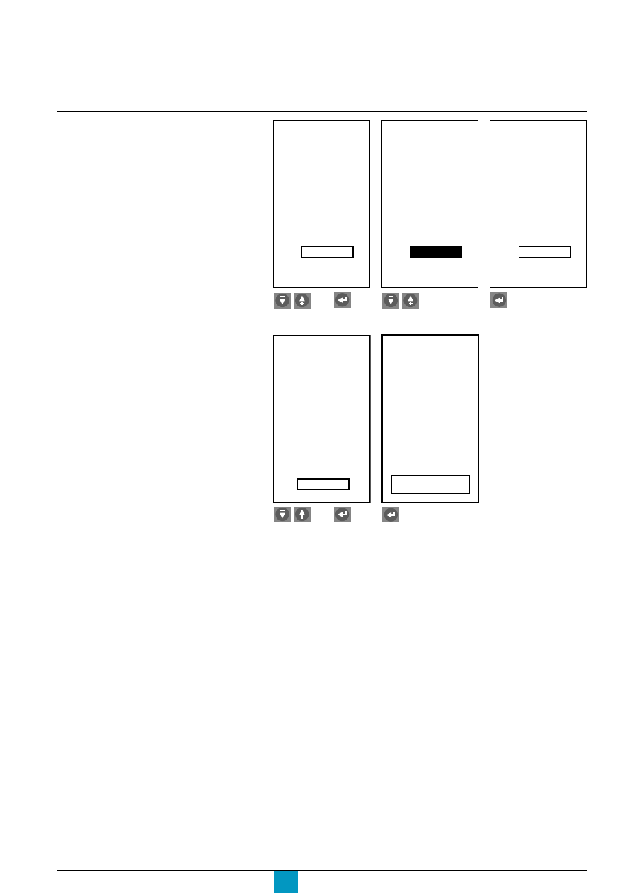
Micrologic P
Schneider Electric
47
For protection tripped by a maximum value,
the dropout threshold is always less than or
equal to the pickup threshold.
For protection tripped by a minimum value,
the dropout threshold is always greater
than or equal to the pickup threshold.
E71665A
E71666A
E71667A
Select the existing
Adjust.
Confirm.
dropout threshold setting
Alarm
U
max
(V)
690V
Pick up
Drop out
5.00s
690V
0.50s
U
max
(V)
690V
5.00s
685V
0.50s
Pick up
Drop out
Alarm
U
max
(V)
690V
5.00s
685V
0.50s
Pick up
Drop out
Alarm
E71668A
E71657A
Make another setting or
Confirm.
exit the menu
and confirm.
U
max
(V)
690V
5.00s
685V
0.50s
Pick up
Drop out
Alarm
No
Yes
Do you want
to save new
settings?
then
then
When all the settings have been made,
quit the screen by pressing one of the
menu-access buttons.
This saves the new values.
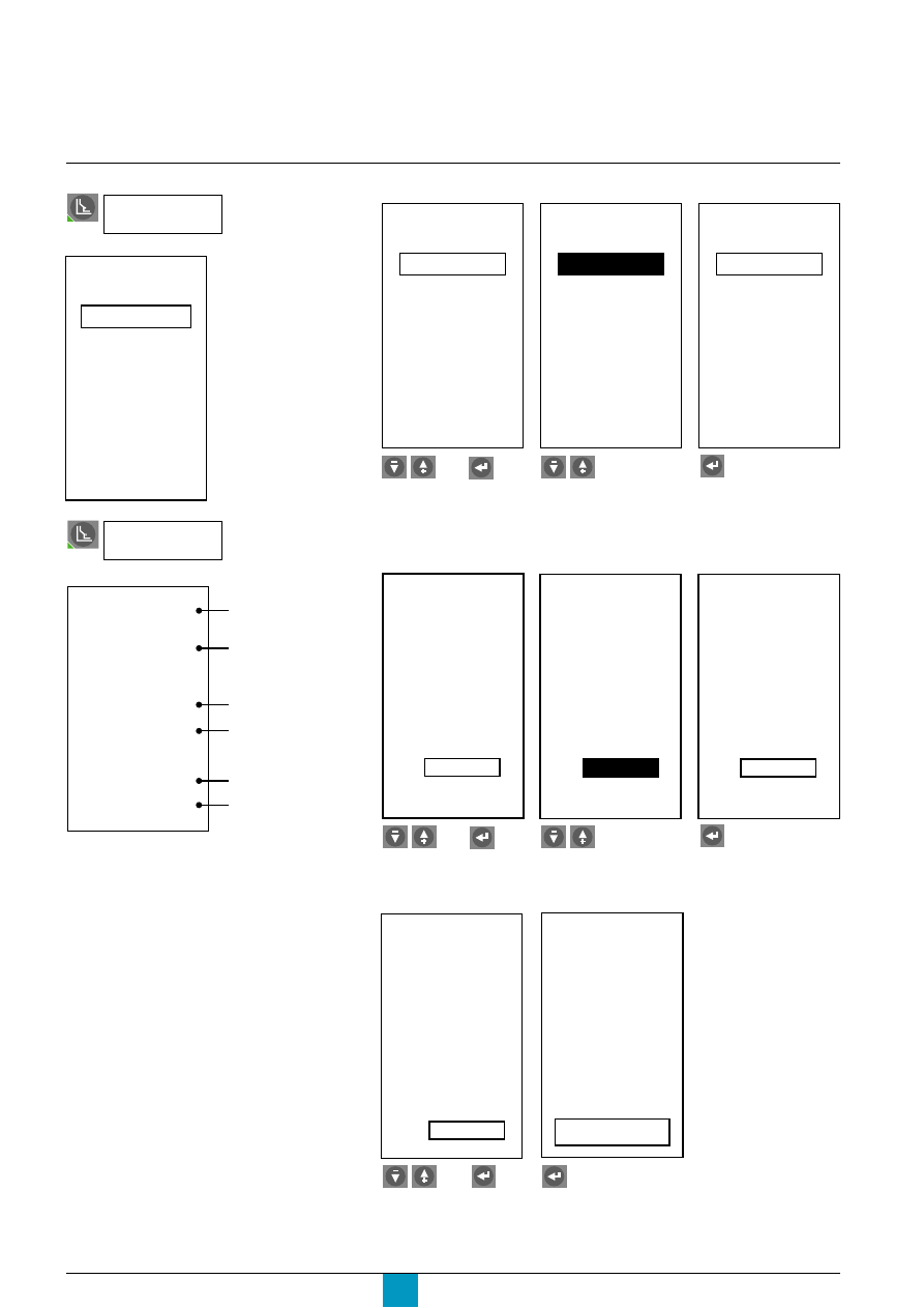
Micrologic P
Schneider Electric
48
E71670A
E71671A
Select the first setting.
Select:
c
Off: load shedding
disabled
c
On: load shedding
enabled.
E71672A
For example, take load shedding / reconnection depending on power.
Confirm.
E71674A
E71675A
E71676A
Select the existing
dropout threshold.
Adjust.
Confirm.
E71677A
E71657A
Make another setting or
exit the menu and
confirm.
Confim.
depending on power
Setting load
shedding / reconnection
P
1000kW
Off
Pick up
Drop out
3600s
1000kW
10s
Load
shedding
Pick up
Drop out
Load
shedding
P
1000kW
On
3600s
1000kW
10s
Pick up
Drop out
Load
shedding
P
1000kW
On
3600s
1000kW
10s
Pick up
Drop out
Load
shedding
P
1000kW
On
3600s
980kW
10s
Pick up
Drop out
Load
shedding
P
1000kW
On
3600s
985kW
10s
Pick up
Drop out
Load
shedding
P
1000kW
On
3600s
985kW
10s
Pick up
Drop out
Load
shedding
P
1000kW
On
3600s
985kW
10s
Select the command
Load
shedding I
depending on current
Load
shedding P
No
Yes
Do you want
to save new
settings?
Pick up
Drop out
Load
shedding
I
100%Ir
Off
80%tr
100%Ir
10s
E71669A
E71673A
then
then
then
Protection settings
When all the settings have been made,
quit the screen by pressing one of the
menu-access buttons.
This saves the new values.
P
1000kW
On
Pick up
Drop out
3600s
1000kW
10s
Load
shedding
type of protection
alarm
pickup time delay
dropout threshold
pickup threshold
dropout time delay

Micrologic P
Schneider Electric
49
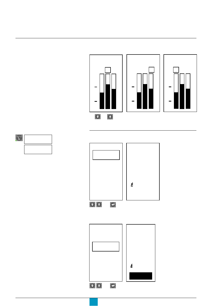
Micrologic P
Schneider Electric
50
Metering
Current measurements
Continuous current measurement
The bargraph displays the value in amperes of the most heavily loaded phase.
E60184A
E60185A
E60187A
Measure all the instantaneous-current values
c
measure the instantaneous currents
E60188A
E60189A
Select.
View.
Only the measurements for the phase
(1, 2, 3) and neutral currents are displayed
on the main screen.
4260A
1 2 3
100
50
0
3850A
1 2 3
100
50
0
3410A
1 2 3
100
50
0
The and buttons may be used to display the currents on the three
phases. If the operator no longer uses the buttons for a few seconds, the bargraph
returns to the display of the most heavily loaded phase.
Max
I
1
, I
2
, I
3
, I
N
inst.
I
I
3
= 3850 A
I
2
= 4260 A
I
1
= 3410 A
inst.
I
= 13 A
I
I
N
= 200 A
c
check the instantaneous-current maximeter
E60190A
E60191A
Max
I
1
, I
2
, I
3
, I
N
inst.
I
I
3
=
I
2
=
I
1
=
instant.
Imax
=
I
Reset ( - / + )
4700 A
4800 A
5600 A
28 A
I
N
=
800 A
Select.
View.
Select the command
I
(A)
then
then
Instant.
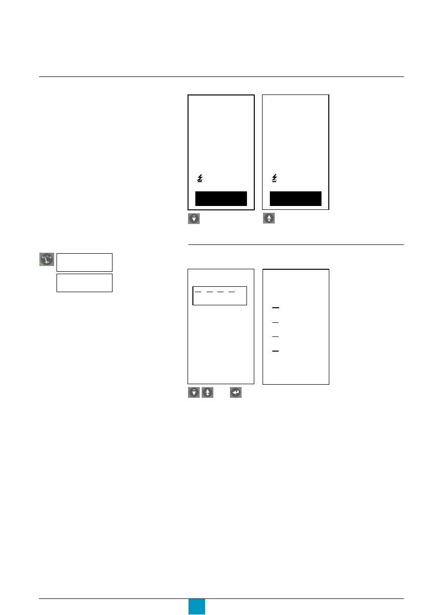
Micrologic P
Schneider Electric
51
c
reset the maximeter
E60192A
E60191A
Measure all the demand-current values
c
measure the demand currents
E71678A
E71679A
Select.
View.
I
3
=
I
2
=
I
1
=
instant.
Imax
=
I
Reset ( - / + )
0 A
0 A
0 A
0 A
I
N
=
0 A
Reset the maximeter or...
cancel the reset.
I
3
=
I
2
=
I
1
=
instant.
Imax
=
I
Reset ( - / + )
4700 A
4800 A
5600 A
28 A
I
N
=
800 A
I
1
, I
2
, I
3
, I
N
Max
Demand
Demand
I
1
=
3950 A
I
2
=
4270 A
13min
I
3
=
3890 A
I
N
=
340 A
then
Select the command
I
(A)
Demand.
E60191A
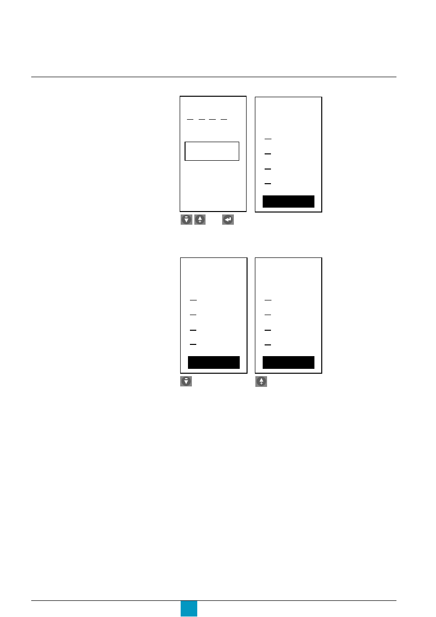
Micrologic P
Schneider Electric
52
Metering
Current measurements
E71680A
E71681A
E71682A
E71683A
Reset the maximeter or...
cancel the reset.
c
check the demand-current maximeter
I
1
, I
2
, I
3
, I
N
Demand
Max
I
1
=
I
2
=
I
3
=
Imax
Demand
Reset ( - / +)
4020 A
4450 A
4300 A
15min
I
N
=
600 A
Select.
View.
c
reset the maximeter
I
1
=
I
2
=
I
3
=
Imax
Demand
Reset ( - / +)
0 A
0 A
0 A
15min
I
N
=
0 A
I
1
=
I
2
=
I
3
=
Imax
Demand
Reset ( - / +)
4020 A
4450 A
4300 A
15min
I
N
=
600 A
then
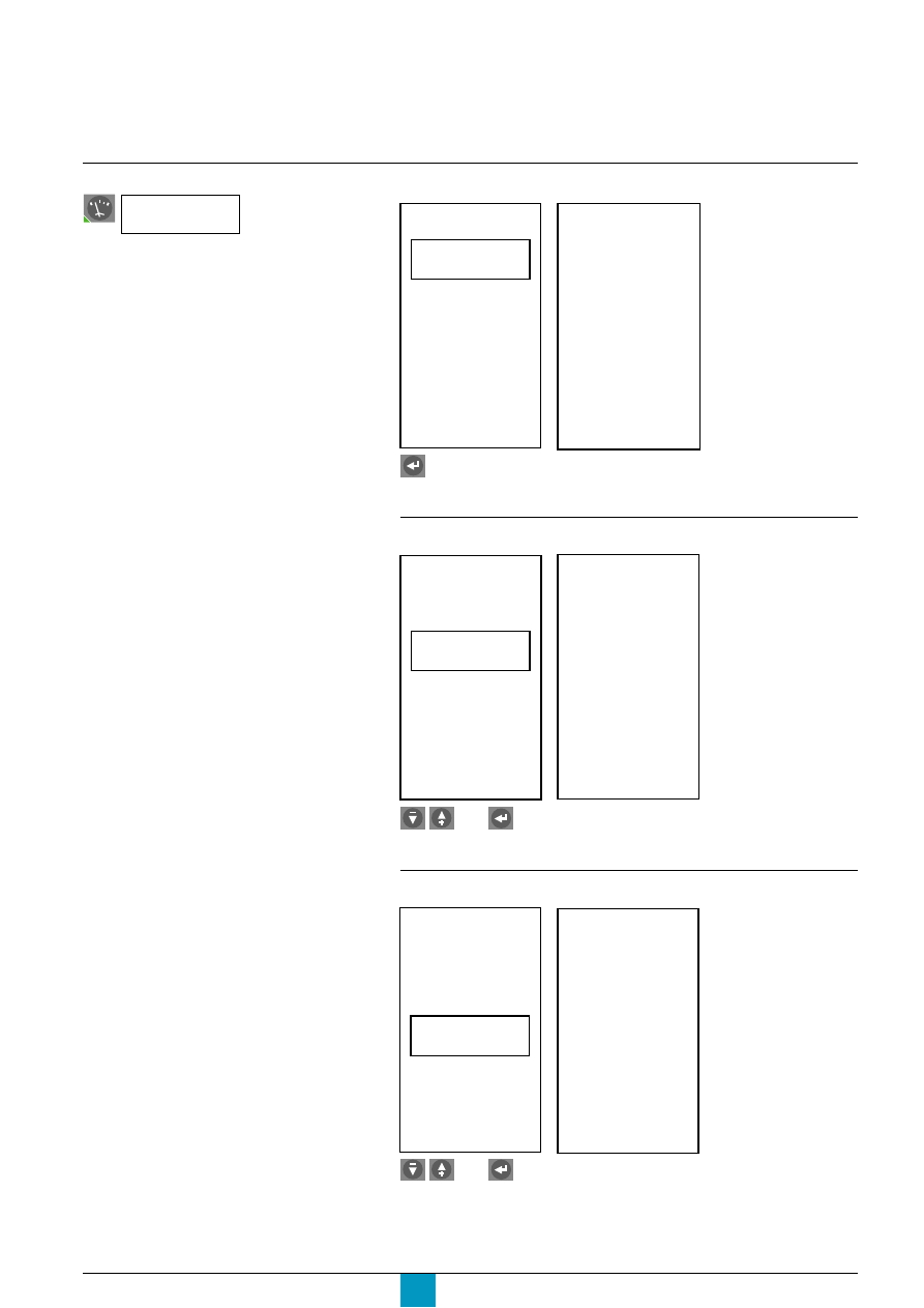
Micrologic P
Schneider Electric
53
Voltage measurements
E71684A
E60193A
Select.
View.
Measure the voltage unbalance U unbal
E71688A
E71689A
Select.
View.
Measure the instantaneous-voltage values (U or V)
U
(V)
Average 3
Φ
Instant.
Unbal 3
Φ
U
12
=
U
23
=
U
31
=
inst.
U
400 V
404 V
401 V
U
1N
=
U
2N
=
U
3N
=
230 V
229 V
233 V
Measure the average voltage U avg
E71687A
Select.
View.
E71686A
Average 3
Φ
Unbal 3
Φ
U
(V)
Instant.
402 V
3
Φ
Uavg.
Average 3
Φ
Unbal 3
Φ
U
(V)
Instant.
1 %
3
Φ
Uunbal
then
then
Select the command
U
(V)
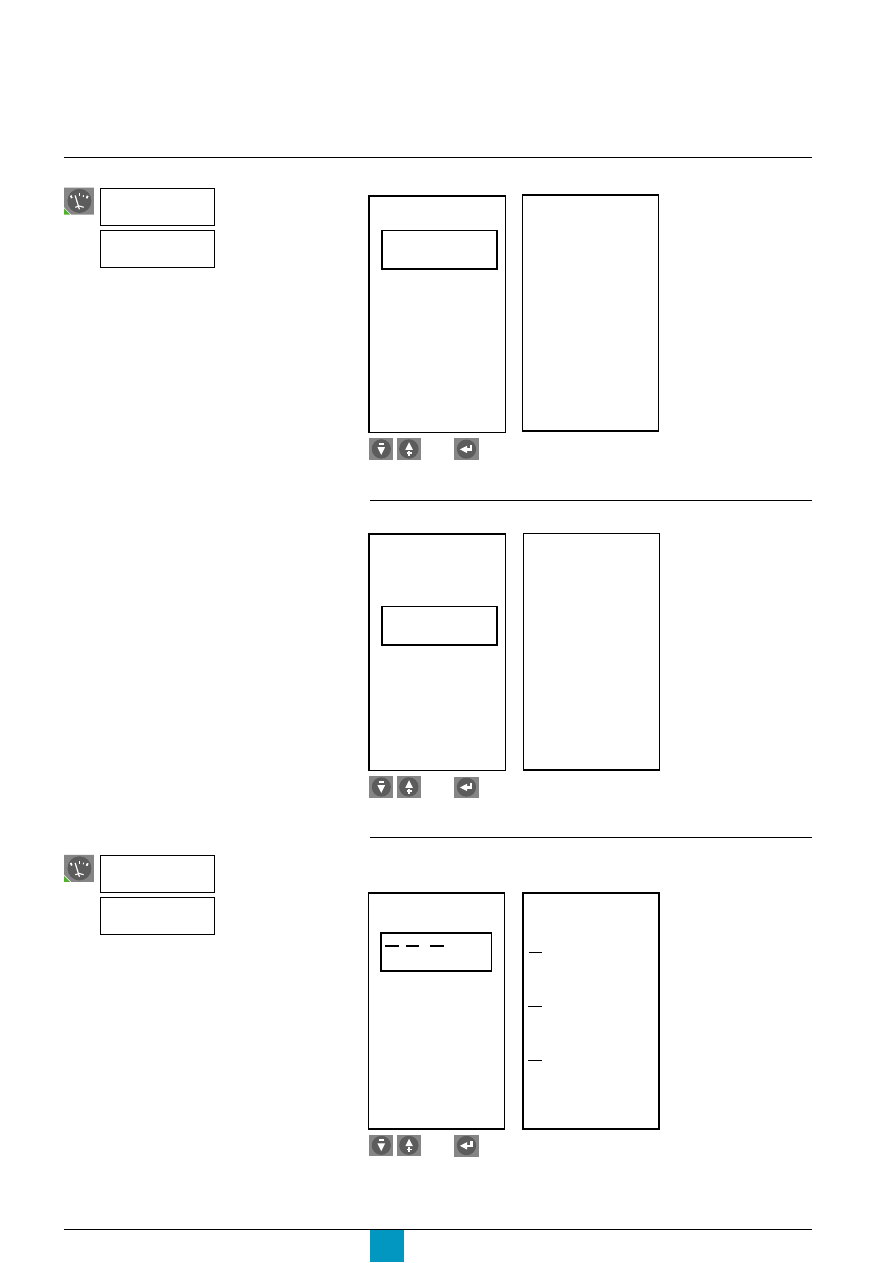
Micrologic P
Schneider Electric
54
Metering
Power measurements
To ensure that the power and power-factor
measurements are reliable, the power sign
convention must first be set in the "History,
maintenance and setup" menu.
E71690A
E60199A
Select.
View.
Measure the demand-power values
c
measure the demand power
E71693A
E71694A
Select.
View.
Measure the instantaneous-power values
Measure the power factor
E71692A
Select.
View.
E71691A
Pinst.
P, Q, S
Power
factor
Pinst.
(kW)
(kvar)
(kVA)
+2180
-650
+2280
P
Q
S
Pinst.
P, Q, S
Power
factor
Power
factor
1.00
P, Q, S
Demand
Max
Demand
(kW)
(kvar)
(kVA)
+2350
-820
+2640
P
Q
S
Select the command
then
Select the command
P
(kW)
then
then
P
(kW)
Instant.
Demand
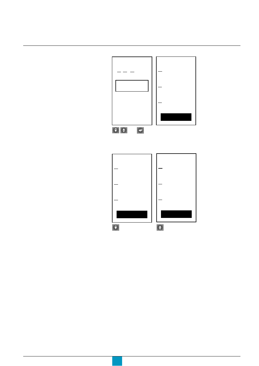
Micrologic P
Schneider Electric
55
c
check the demand-power maximeter
E71695A
E71696A
P, Q, S
Demand
Max
Pmax
Demand
Reset (- / +)
(kW)
(kvar)
(kVA)
+2450
-800
+2700
P
Q
S
Select.
View.
c
reset the maximeter
E71697A
E71698A
Reset the maximeter or...
cancel the reset.
Pmax
Demand
Reset (- / +)
(kW)
(kvar)
(kVA)
+0
+0
+0
P
Q
S
Pmax
Demand
Reset (- / +)
(kW)
(kvar)
(kVA)
+2450
-800
+2700
P
Q
S
then
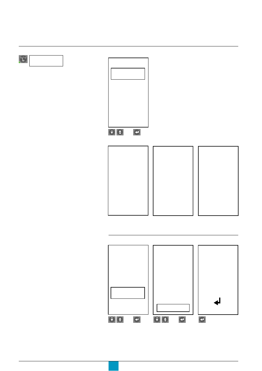
Micrologic P
Schneider Electric
56
Metering
Energy measurements
To ensure that the energy measurements
are reliable, the energy sign convention first
be set in the "History, maintenance and
setup" menu.
Measure the energy values
E71699A
Select.
E
E total
energy
Reset
E in
E out
(kWh)
Select the energy value to be measured:
c
total energy
c
energy in (positive component in the total energy)
c
energy out (negative component in the total energy).
Select the command
E
(kWh)
then
E71700A
View the total energy
values.
E total
(kWh)
(kvarh)
(kVAh)
+20168
-2733
+22926
E.P
E.Q
E.S
E71701A
E in
(kWh)
(kvarh)
+21320
-2770
E.P
E.Q
E71702A
(kWh)
(kvarh)
+168
-33
E.P
E.Q
E out
Reset the energy values
E71703A
Select.
Select yes or no.
If yes, confirm.
E71704A
E71705A
E
E total
Energy
Reset
E in
E out
(kWh)
Reset
Energy
No
Yes
Are you
sure ?
To reset
energy
press
enter
then
then
View the energy
in values.
View the energy
out values.
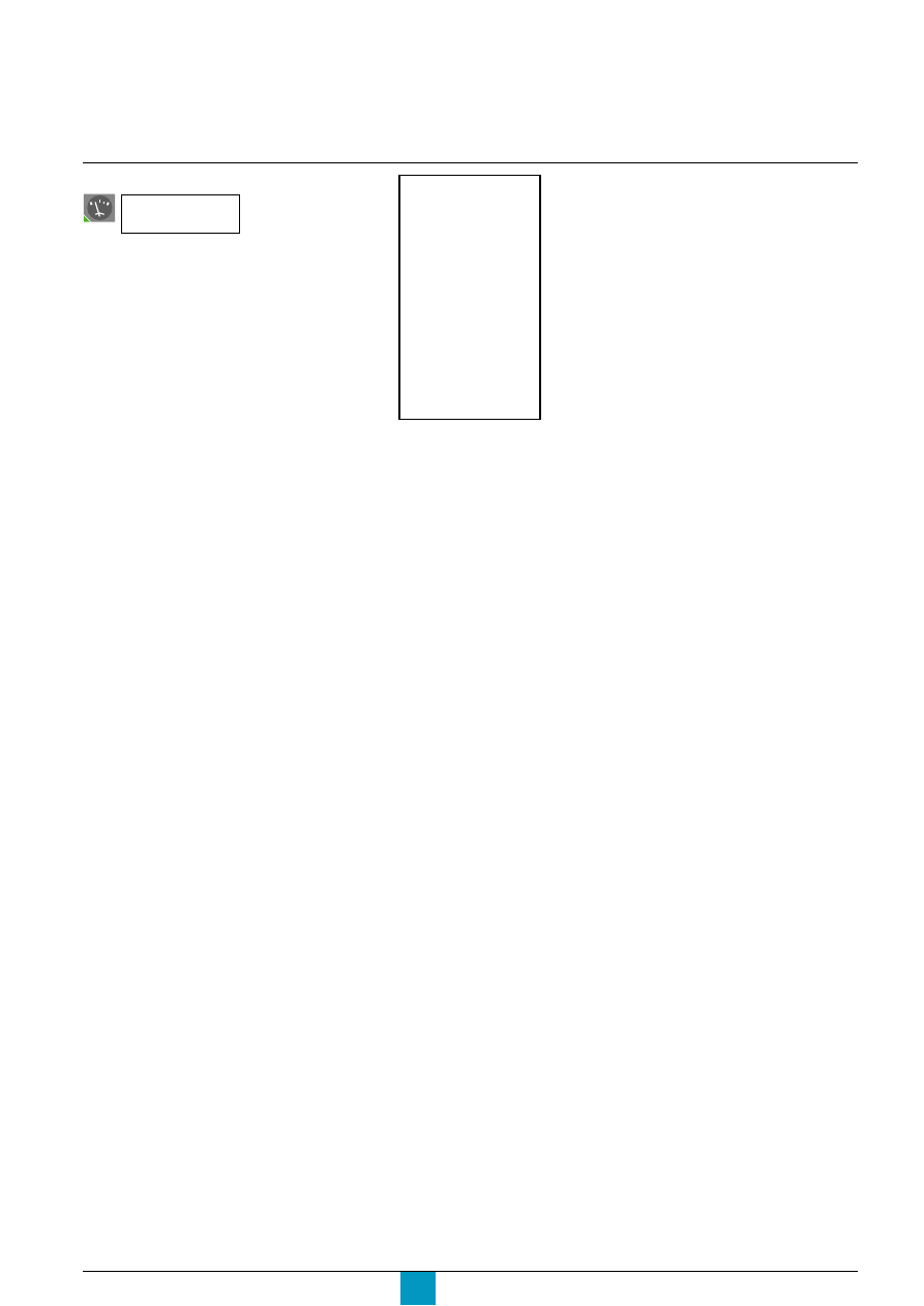
Micrologic P
Schneider Electric
57
Frequency measurements
E60110A
F
(Hz)
60.0
View.
Select the command
F
(Hz)
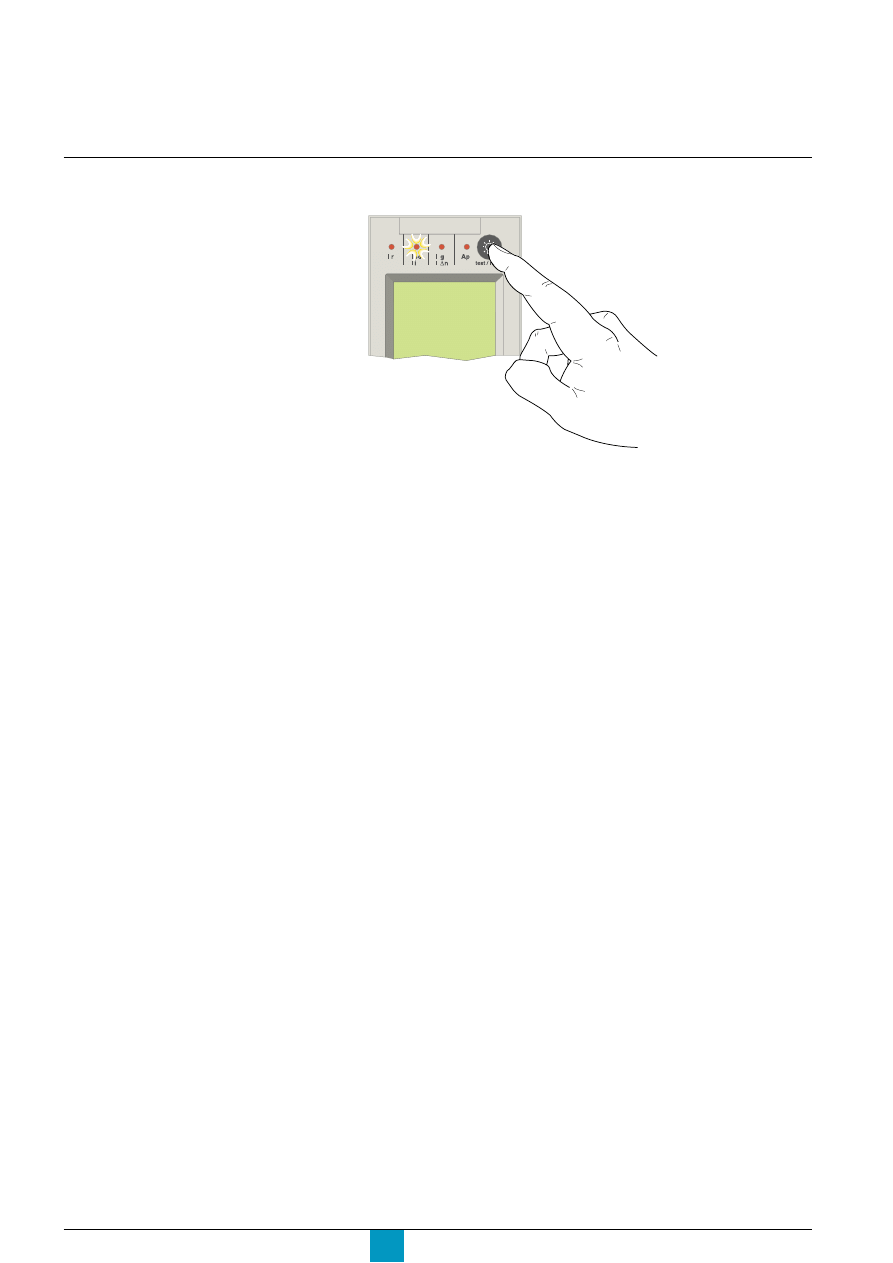
Micrologic P
Schneider Electric
58
Maintenance
Resetting fault indications
E60306A
Caution!
If the circuit breaker remains closed and
the Ap LED remains ON after the reset,
open the circuit breaker and contact the
after-sales support department.
The fault indication is maintained until it is reset on the control panel.
Press the reset button.
Micrologic 7.0 P
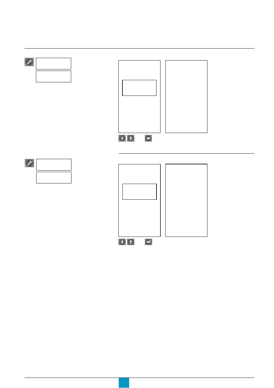
Micrologic P
Schneider Electric
59
Viewing the event histories
E71706A
E71707A
Select a fault.
View.
E71708A
E71709A
Select an alarm.
View.
Trip history
Trip
history
27/01/1999
U
min
27/06/1998
Ir
18/02/1998
Ir
Trip
02:04:04
22/11/1999
Umin 160V
Alarm history
23/03/1998
Alarm
history
U max
I2 max
In max
27/01/1999
12/02/1998
Alarm
13:06:09
27/01/1999
I2 max 3400A
Select the command
Event
history
Trip
history
Select the command
Event
history
Alarm
history
then
then
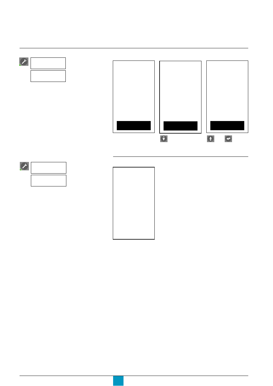
Micrologic P
Schneider Electric
60
Maintenance
Operation counter and
contact-wear indicator
View and/or reset the operation counter
Check the wear of the contacts
E71710A
0
Contact
wear
Select the command
Event
history
Operation
counter
Select the command
Event
history
Contact
wear
E71736A
Reset.
Or cancel the reset,
then confirm.
Operations
since last
reset
operations
Number of
17824
Total
0
Reset ( - / + )
E717737A
Operations
since last
reset
operations
Number of
17824
Total
6923
Reset ( - / + )
then
Operations
since last
reset
17824
Total
operations
Number of
6923
Reset ( - / + )
E71735A
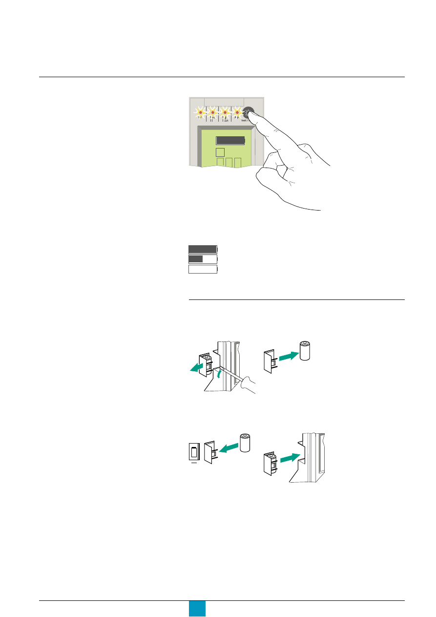
Micrologic P
Schneider Electric
61
If the battery must be replaced, use a new
battery with the Schneider part number
33593 (technical characteristics available
on the battery-slot cover).
Check its condition regularly by pressing
and holding down the test button on the
control unit for several seconds.
Checking the battery
E60307A
Test the control-unit
Micrologic 7.0 P
1 2 3
Press and hold down the test button on the control unit to check the battery.
Information is displayed if the circuit breaker is closed or if it is open and equipped
with an external power supply.
If no information is displayed, the control unit is operating under the conditions
described in the "Power supply" section in the technical appendix.
Replacing the control-unit battery
E71751A
1. remove
2. remove the battery
the battery cover
E60308A
E51443A
E60473A
E60481A
3. insert a new battery.
4. put the cover back
Check the polarity.
in place. Press the
battery-test button to
check the new battery.
+
Battery fully charged
Battery half charged
No battery or must be replaced
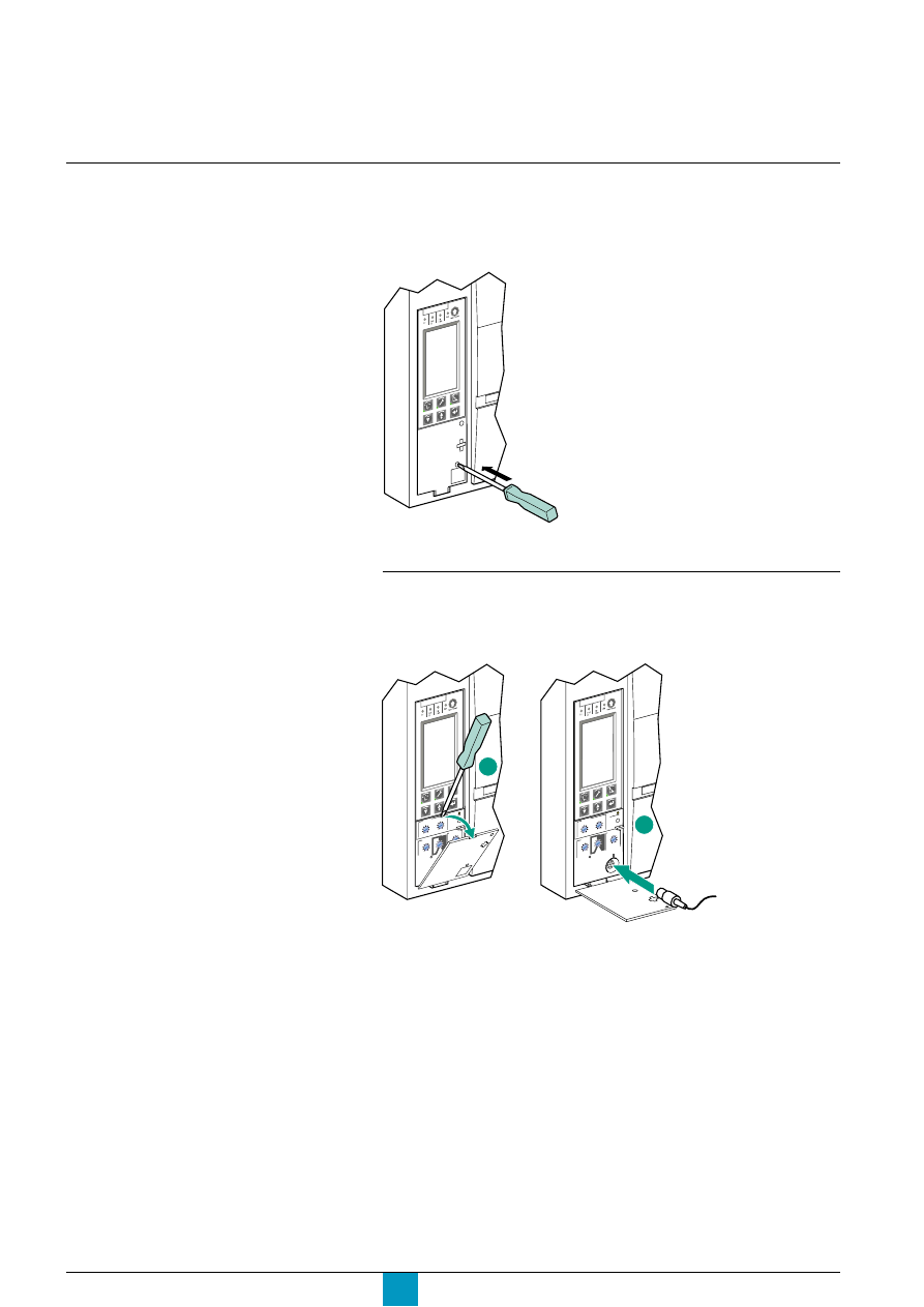
Micrologic P
Schneider Electric
62
Maintenance
Test the earth-fault (Micrologic 6.0 P) and earth-leakage
(Micrologic 7.0 P) protection functions
The circuit breaker must be supplied with power and closed for the test.
Press the TEST button. The circuit breaker should trip.
Refer to the manual that comes with the
test kits.
Tests
E60309A
E60310A
E60311A
Micr
ologic 5.0 P
If the circuit breaker does not trip, contact the after-sales support department.
Mini test kit and portable test kit
The test connector is used to connect the mini or the portable test kit to check that
the control unit is operating correctly.
Micro
logic
5.0 P
1
Micr
ologic 5.0 P
2

Micrologic P
Schneider Electric
63
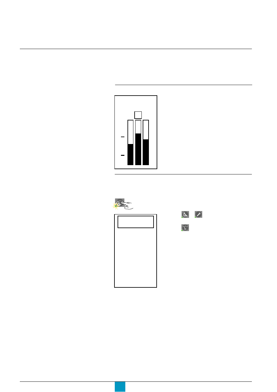
Micrologic P
Schneider Electric
64
Menu access
Selecting the main menus
The Micrologic P control unit offers access to the main screen and three menus:
c
the main screen displaying the continuous measurement of the phase currents
(I1, I2, I3) and the neutral current (In), if it exists
c
the "Metering" menu
c
the "History, maintenance and setup" menu
c
the "Protection" menu.
Main screen
E60101A
4260A
1 2 3
100
50
0
"Metering", "History, maintenance and setup" and
"Protection" menus
E60102A
I
U
(V)
(kW)
(A)
E
(kWh)
P
F
(Hz)
v
press the or button to return to the main
screen
v
press the button to return to the previous
screen
v
whatever the screen displayed, if no further action is
taken, the system returns to the main screen after a
few minutes
v
the LED goes OFF on exiting the menu.
As long as no functions are activated, Micrologic P
control units display in real time the current on the
most heavily loaded phase.
The number for that phase is presented in a square.
When a menu button is pressed, a
presentation screen is displayed and the
green LED on the button goes ON.
c
"Metering" menu
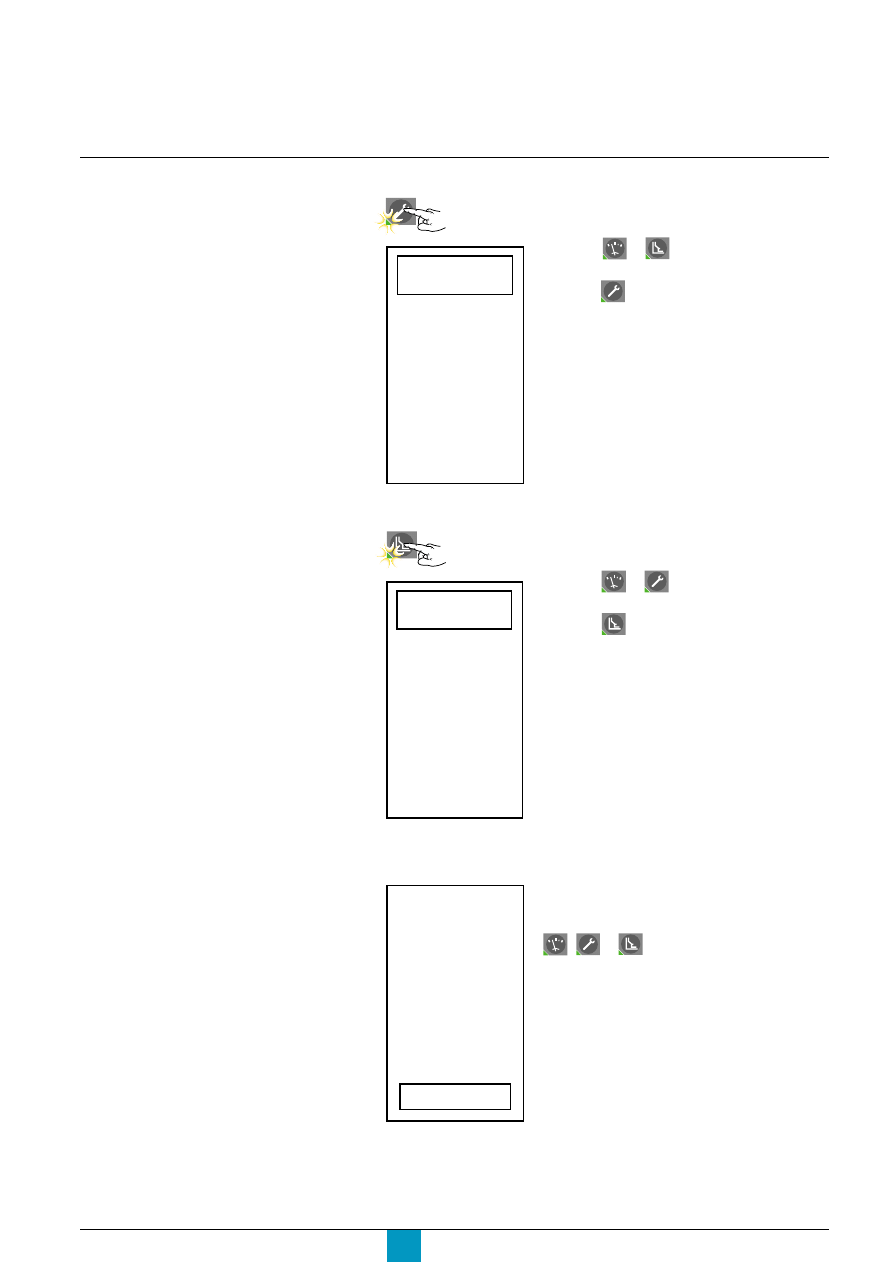
Micrologic P
Schneider Electric
65
E71657A
No
Yes
Do you want
to save new
settings?
c
saving settings
E71711A
E71712A
Event
history
setup
Metering
Contacts
M2C / M6C
Micrologic
setup
setup
Com.
I
P
Current
protection
Voltage
protection
Other
protection
Load
shedding
Load
shedding
c
"History, maintenance and setup" menu
v
press the or button to return to the main
screen
v
press the button to return to the previous
screen
v
whatever the screen displayed, if no further action is
taken, the system returns to the main screen after a
few minutes
v
the LED goes OFF on exiting the menu.
c
"Protection" menu
v
press the or button to return to the main
screen
v
press the button to return to the previous
screen
v
whatever the screen displayed, if no further action is
taken, the system returns to the main screen after a
few minutes
v
the LED goes OFF on exiting the menu.
When a setting is made in any of the three menus, the
screen used to save the modification(s) may be
accessed by pressing one of the three buttons
,
or
.
v
select yes to save the modifications
v
select no to cancel and maintain the previous
settings
v
this screen remains displayed until yes or no are
selected.
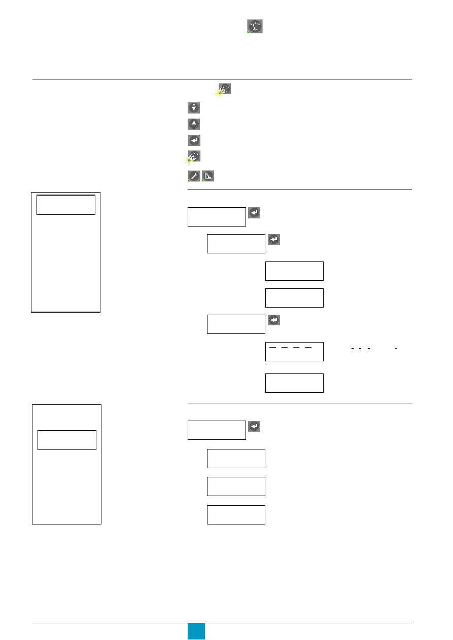
Micrologic P
Schneider Electric
66
Menu access
Metering
Press the button to select the "Metering" menu.
move the cursor down the screen or decrement a value.
move the cursor up the screen or increment a value.
select an option in a list, confirm a selection or the value of a setting.
indicates that the operator is in the "Metering" menu and returns
to the previous screen.
return to the main screen.
Current measurements
E60105A
I
U
(V)
(kW)
(A)
E
(kWh)
P
F
(Hz)
E60391A
I
U
(V)
(kW)
(A)
E
(kWh)
P
F
(Hz)
I
(A)
access to the following sections:
Instant.
I1, I2, I3, IN
I1, I2, I3, IN currents
(depending on the type of
system)
Max
Storing and reset of
the maximeter
Demand
I1, I2, I3, IN
Demand current on the
phases 1, 2, 3 and on N
(depending on the type of
system).
Max
Storing and reset of the
maximeter
Voltage measurements
I
I
I
U
(V)
access to the following sections:
Instant.
Instantaneous phase-to-phase U12, U23, U31 and
phase-to-neutral V1N, V2N, V3N voltages
(depending on the type of system)
Average 3
Φ
Average voltage U average of the phase-to-phase
voltages.
Unbal 3
Φ
Unbalance voltage U unbal. of the phase-to-phase
voltages.
I
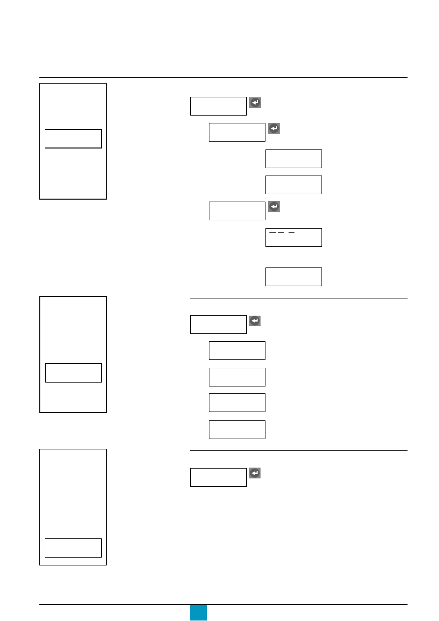
Micrologic P
Schneider Electric
67
E60392A
I
U
(V)
(kW)
(A)
E
(kWh)
P
F
(Hz)
E60393A
I
U
(V)
(kW)
(A)
E
(kWh)
P
F
(Hz)
E60394A
I
U
(V)
(kW)
(A)
E
(kWh)
P
F
(Hz)
Power measurements
P
(kW)
access to the following sections:
Instant.
P, Q, S,
Total active power P
Total reactive power Q
Total apparent power S
Power
factor
Power factor PF
Demand
P, Q, S
Max
Demand values for the:
c
total active power P
c
total reactive power Q
c
total apparent power S
Storing and reset of the
maximeter
Energy measurements
E
(kWh)
access to the following sections:
E total
E in
Total active energy E.P
Total reactive energy E.Q
Total apparent energy E.S
Positive component of:
c
the total active energy E.P
c
the total reactive energy E.Q
E out
Negative component of:
c
the total active energy E.P
c
the total reactive energy E.Q
Reset
Energy
Reset all the energy values to zero
Frequency measurement
F
(Hz)
access to the frequency (F) measurement
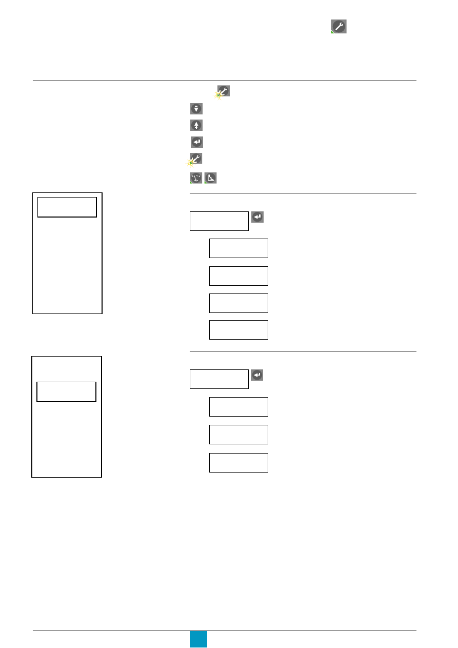
Micrologic P
Schneider Electric
68
Menu access
History, maintenance
and setup
Press the button to select the "History, maintenance and setup" menu.
move the cursor down the screen or decrement a value.
move the cursor up the screen or increment a value.
select an option in a list, confirm a selection or the value of a setting.
indicates that the operator is in the "History, maintenance and setup" menu
and returns to the previous screen.
return to the main screen.
E71711A
E71713A
Event
history
setup
Metering
Contacts
M2C / M6C
Micrologic
setup
setup
Com.
Event
history
setup
Metering
Contacts
M2C / M6C
Micrologic
setup
setup
Com.
Event history
access to the following sections:
Trip
history
The last ten alarms activated
Number of operations (opening or closing)
Contact
wear
M2C / M6C Contacts
Event
history
The last ten faults recorded following a trip
Alarm
history
Operation
counter
Wear of the circuit-breaker main contacts
access to the following sections:
Contacts
M2C / M6C
Assignment of a protection alarm set for each M2C
or M6C contact
Setup
Latching mode for each M2C or M6C contact
Reset
Reset of the M2C or M6C contacts to zero following
activation of an alarm
Alarm
type
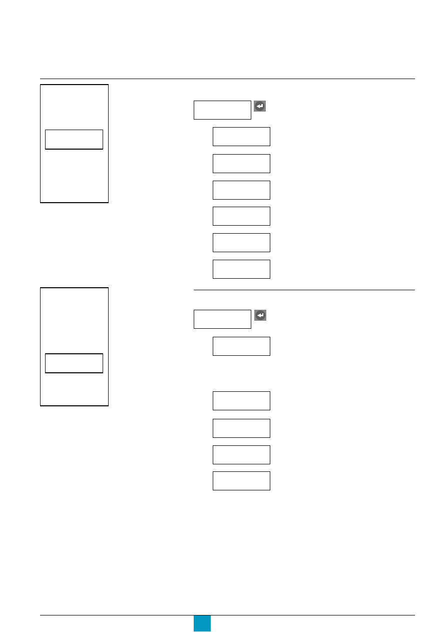
Micrologic P
Schneider Electric
69
Micrologic setup
E71714A
E71715A
Event
history
setup
Metering
Contacts
M2C / M6C
Micrologic
setup
setup
Com.
Event
history
setup
Metering
Contacts
M2C / M6C
Micrologic
setup
setup
Com.
access to the following sections:
Language
Setting of the date and time
Indication of the circuit-breaker type
Metering setup
Micrologic
setup
Selection of the display language
Date / hour
Breaker
selection
Selection of the neutral-CT type
Neutral TC
Selection of the voltage transformation ratio when
an external voltage transformer is installed
VT ratio
Indication of the rated system frequency
System
frequency
access to the following sections:
Metering
setup
c
3 phases, 3 wires, 3 CTs: method using two
wattmeters
c
3 phases, 4 wires, 3 CTs: method using three
wattmeters
c
3 phases, 4 wires, 4 CTs: method using three
wattmeters with measurement of the neutral
current.
Current
demand
Setting of the time interval for the calculation
Setting of the parameters for the calculation
System
type
Power
demand
Setting of the normal direction of active-power flow
Active P
flow
Setting of the sign convention for the power factor
and reactive power
Sign
convention
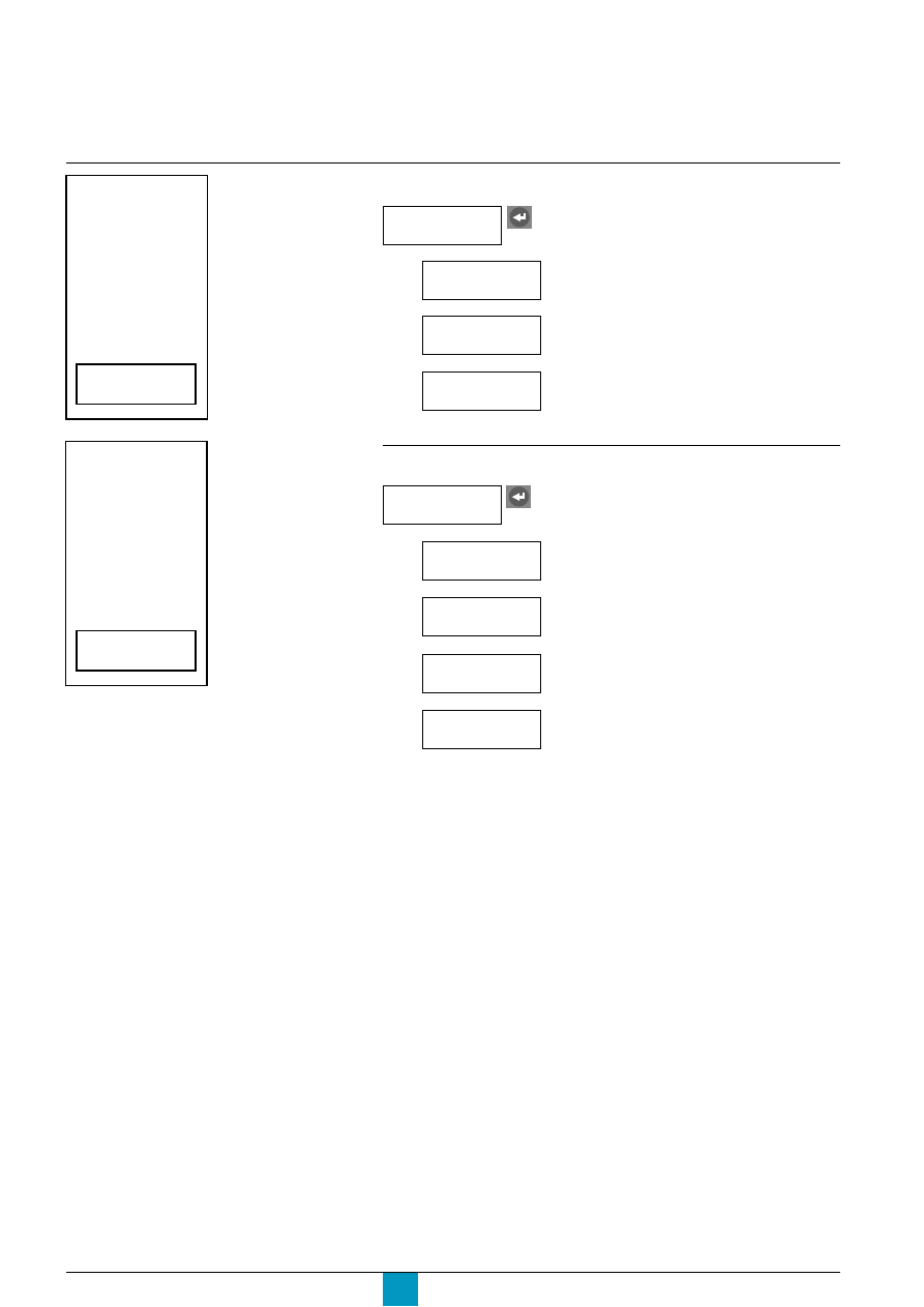
Micrologic P
Schneider Electric
70
Menu access
History, maintenance and setup
E71716A
E71717A
Event
history
setup
Metering
Contacts
M2C / M6C
Micrologic
setup
setup
Com.
setup
Metering
Micrologic
setup
Contacts
M2C / M6C
setup
setup
Protection
Com.
COM communications-option setup
access to the following sections:
Com.
parameter
Authorisation or refusal of access via
the COM communications option.
Access to the circuit-breaker ON and OFF
commands.
Protection setup
Com.
setup
Setting of parameters for the COM
communications-option (if installed)
Remote
settings
Remote
control
access to the following sections:
Protection
setup
Selection of the Alarm or Trip mode for the current-
protection functions
Voltage
protection
Selection of the Alarm or Trip mode for the voltage-
protection functions
Other
protection
Selection of the Alarm or Trip mode for the other
protection functions
Current
protection
Power
flow
Selection of the power-flow sign convention
(Top fed or Bottom fed).
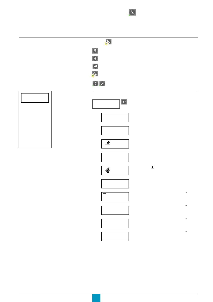
Micrologic P
Schneider Electric
71
Press the button to select the "Protection" menu.
move the cursor down the screen or decrement a value
move the cursor up the screen or increment a value
select an option in a list, confirm a selection or the value of a setting
indicates that the operator is in the "Protection" menu and returns
to the previous screen
return to the main screen
E71712A
I
P
Current
protection
Voltage
protection
Other
protection
Load
shedding
Load
shedding
I
(A)
access to the following sections:
Current
protection
View or fine settings of the long-time I
2
t, short-time
and instantaneous protection functions
Protection
I
dmtl
(A)
View or fine settings of the long-time Idmtl,
short-time and instantaneous protection functions
I
(A)
View or fine settings of the:
c
earth-fault (Micrologic 6.0 P)
c
earth-leakage (Micrologic 7.0 P) protection functions
I
neutral (A)
Selection of the neutral
I
Alarm
Setting of the I alarm.
I
unbal
(%)
Setting of the current-unbalance protection I unbal
Setting of the maximum-current protection 1 max
I
1 max (A)
I
2 max (A)
Setting of the maximum-current protection 2 max
I
3 max (A)
Setting of the maximum-current protection 3 max
Current protection
I
I
I
I
N max (A)
Setting of the maximum-current protection N max
I
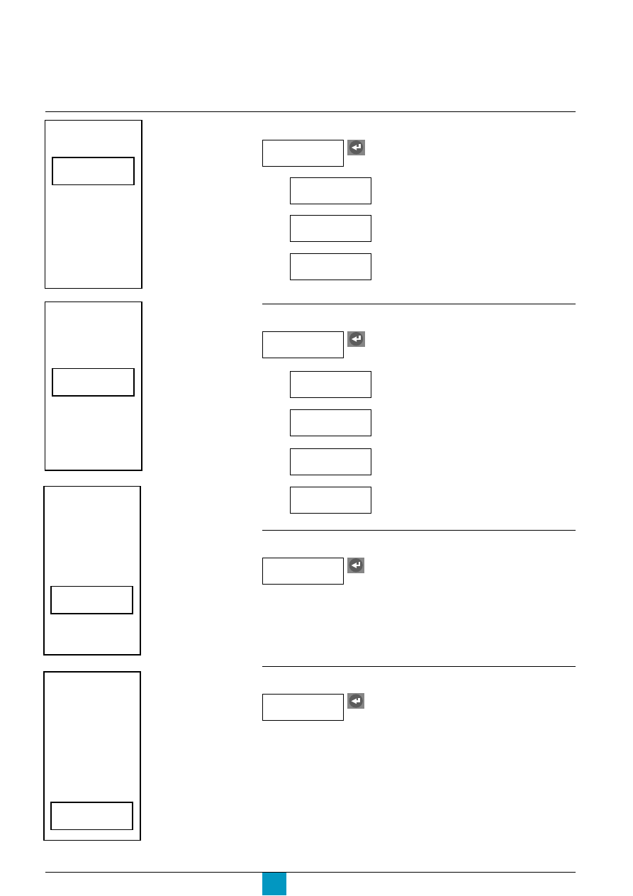
Micrologic P
Schneider Electric
72
Menu access
Protection
E71719A
E71720A
Voltage protection
I
P
Current
protection
Voltage
protection
Other
protection
Load
shedding
Load
shedding
I
P
Current
protection
Voltage
protection
Other
protection
Load
shedding
Load
shedding
E71721A
I
P
Current
protection
Voltage
protection
Other
protection
Load
shedding
Load
shedding
E71722A
I
P
Current
protection
Voltage
protection
Other
protection
Load
shedding
Load
shedding
access to the following sections:
Setting of the maximum-voltage protection U max.
Setting of the voltage-unbalance protection U unbal.
Other protection
Voltage
protection
Setting of the minimum-voltage protection U min.
U
min
(V)
U
max (V)
U
unbal (%)
access to the following sections:
Other
protection
Setting of the reverse-power protection rP max
rP
max (W)
Setting of the minimum-frequency protection F min
F
min (Hz)
Setting of the maximum-frequency protection F max
F
max (Hz)
Setting of the phase-rotation protection
Phase
rotation
Load shedding depending on current
Access to load shedding and reconnection
depending on current
Load
shedding
I
Load shedding depending on power
Access to load shedding and reconnection
depending on power
Load
shedding
P

Micrologic P
Schneider Electric
73
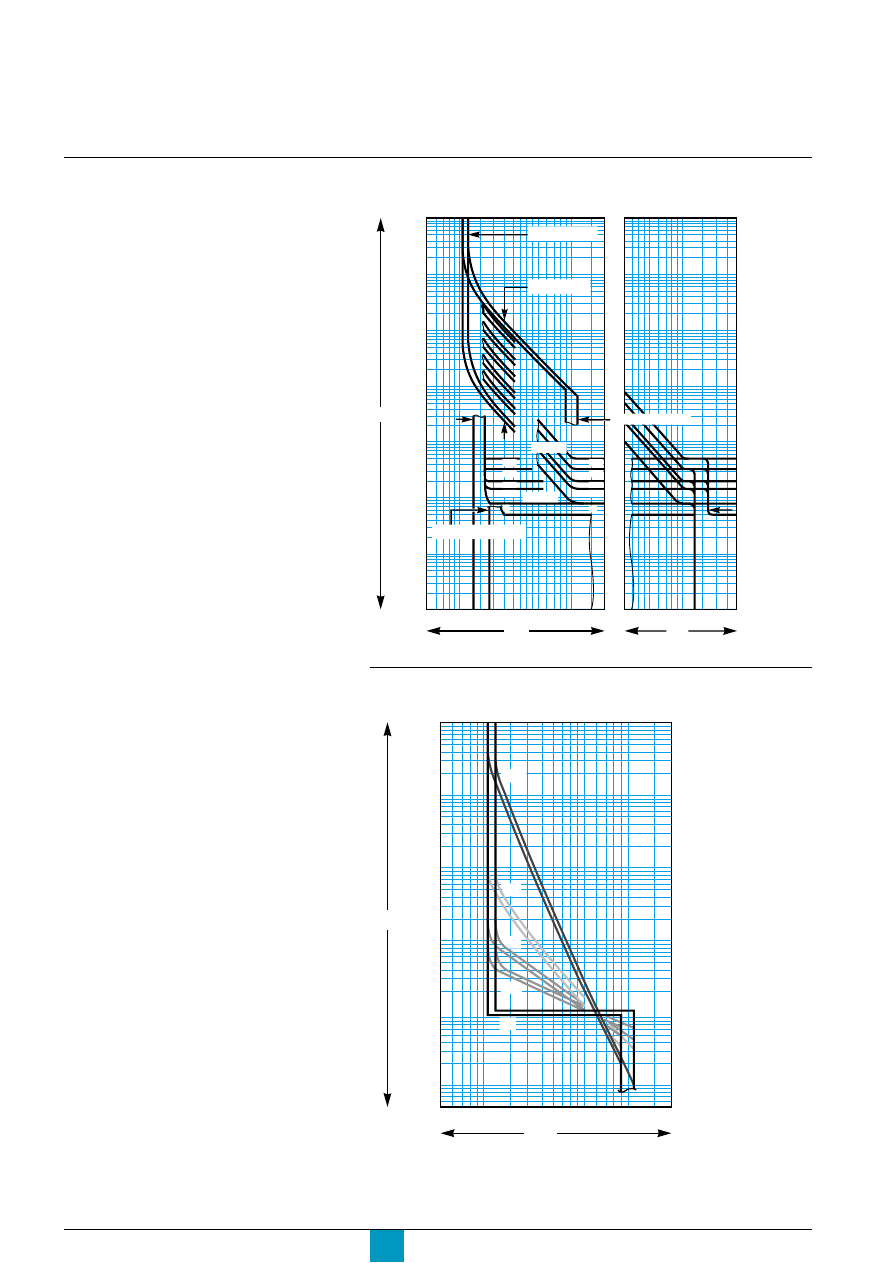
Micrologic P
Schneider Electric
74
Technical appendix
Tripping curves
Long-time I
2
t, short-time and instantaneous protection
Micrologic 5.0 P, 6.0 P, 7.0 P
E71753A
E47587A
0
0.4
0.3
0.2
0.1
t(s)
.5 .7
1
2
3 4 5
7 10
20
3
5
7 10
20 30
10 000
5 000
2 000
1 000
500
200
100
50
20
10
5
2
1
.5
.2
.1
.05
.02
.01
.005
.002
.001
x In
tr = 0.5…24 s
Isd = 1.5…10 x Ir
Ir = 0.4…1 x In
Ii = 2…15 x In . OFF
I
2
t OFF
x Ir
0.4
0.3
0.2
0.1
I
2
t ON
0
Long-time Idmtl, short-time and instantaneous protection
Micrologic 5.0 P, 6.0 P, 7.0 P
DT
VIT
EIT
HVF
SIT
.5
.7
1
2
3
4 5
7
10
20
I / Ir
10 000
5 000
2 000
1 000
500
200
100
50
20
10
5
2
1
.5
100 000
t(s)
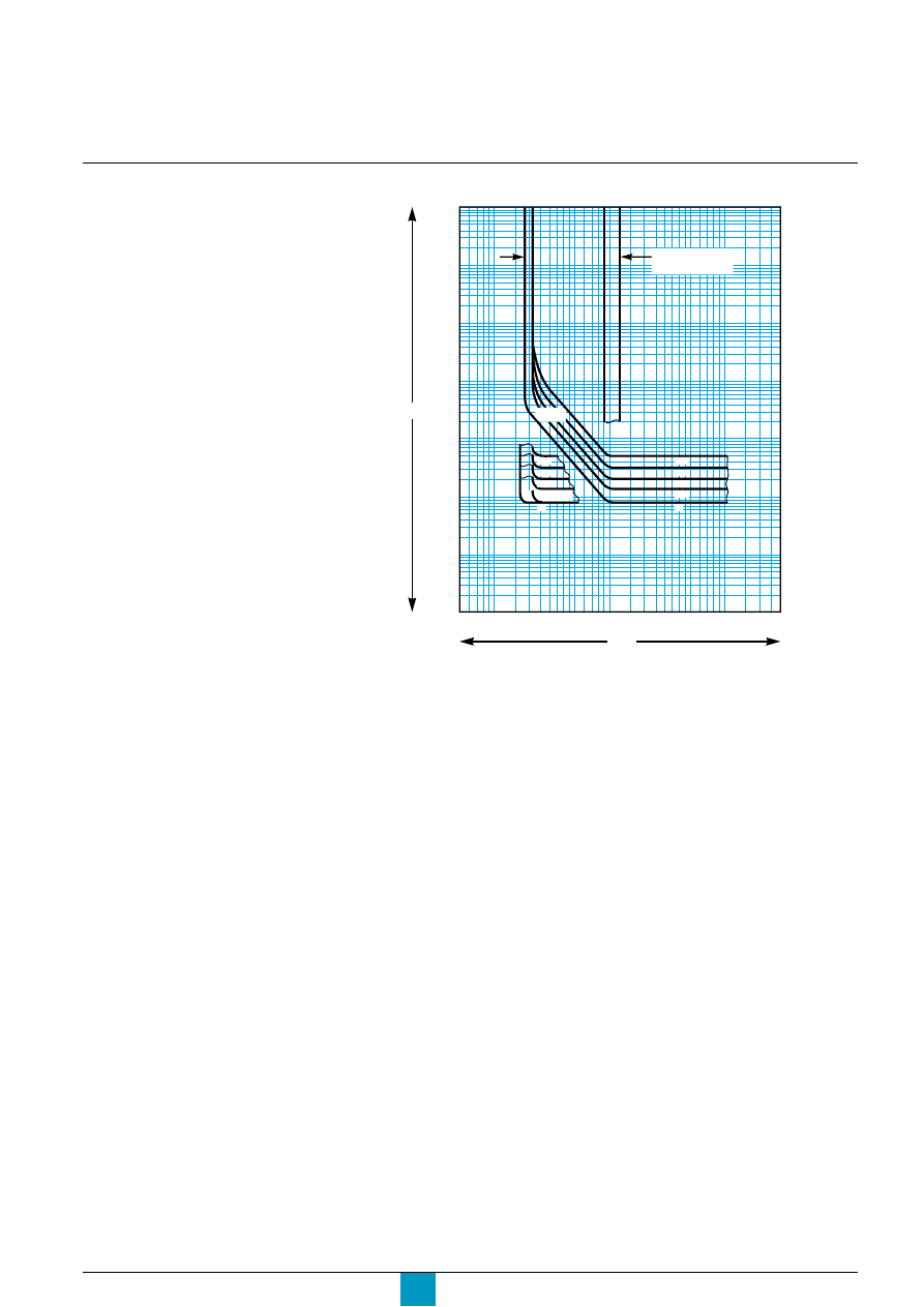
Micrologic P
Schneider Electric
75
Earth-fault protection - Micrologic 6.0 P
E46266A
Ig = A…J x In (1)
1200 A max.
t(s)
I / In
10 000
5 000
2 000
1 000
500
200
100
50
20
10
5
2
1
.5
.2
.1
.05
.02
.01
.005
.002
.001
.05.07 .1
.2
.3 .4 .5 .7 1
2
3
5
7 10
200 300
I
2
t OFF
0.4
0.3
0.2
0.1
I
2
t ON
0.4
0.3
0.2
0.1
0
0
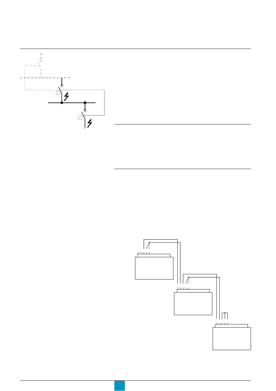
Micrologic P
Schneider Electric
76
Caution:
lf the protection function is not used on
circuit breakers equipped for ZSI
protection, a jumper must be installed to
short terminals Z3, Z4 and Z5. If the jumper
is not installed, the short-time and earth-
fault tripping delays are set to zero,
whatever the position of the adjustment
dial.
Zone selective interlocking (ZSI)
Operating principle
c
a fault occurs at point A
Downstream device no. 2 clears the fault and sends a signal to upstream device
no. 1, which maintains the short-time tripping delay tsd or the earth-fault tripping
delay tg to which it is set.
c
a fault occurs at point B
Upstream device no. 1 detects the fault. In the absence of a signal from a
downstream device, the upstream device immediately trips without taking into
account its tripping-delay settings. If it is connected to a device even further
upstream, it sends a signal to that device, which delays tripping according to its tsd
or tg setting.
Note:
It is advised to maintain a difference of at least one dial setting for the pickup and delay
settings between any two devices and to use the I
2
t OFF setting.
Connections between control units
A logic signal (0 or 5 volts) can be used for zone selective interlocking between the
upstream and downstream circuit breakers.
c
Micrologic 5.0 A, 6.0 A, 7.0 A
c
Micrologic 5.0 P, 6.0 P, 7.0 P
c
Micrologic 5.0 H, 6.0 H, 7.0 H.
An interface is also available for links to previous generations of trip units and to
medium-voltage protection relays.
Wiring
c
maximum impedance: 2.7
Ω
/ 300 metres
c
capacity of connectors: 0.4 to 2.5 mm
2
c
maximum cross-sectional area of wires (including insulation): 3.5 mm
2
c
wires: single or multicore
c
maximum length: 3000 metres
c
limits to device interconnection:
v
the common ZSI - OUT - SOURCE (Z1) and the output ZSI - OUT (Z2) can be
connected to a maximum of ten inputs
v
a maximum of 100 devices may be connected to an input ZSI - IN - ST (Z4) or
GF (Z5)
c
connections are made from the output ZSI - OUT (Z2) on the downstream device
to the input(s) ZSI - IN - ST (Z4) and/or GF (Z5) on the upstream device.
E60450A
A
B
1
2
E71752A
Terminals Z1 to Z5 correspond to the
identical indications on the circuit-breaker
terminal blocks.
Technical appendix
Upstream
circuit breaker
Z1 Z2 Z3 Z4 Z5
Terminal block
for external
connections
Downstream
circuit breaker
and/or
and/or
Z1 Z2 Z3 Z4 Z5
Z1 Z2 Z3 Z4 Z5
Terminal block
for external
connections
Terminal block
for external
connections
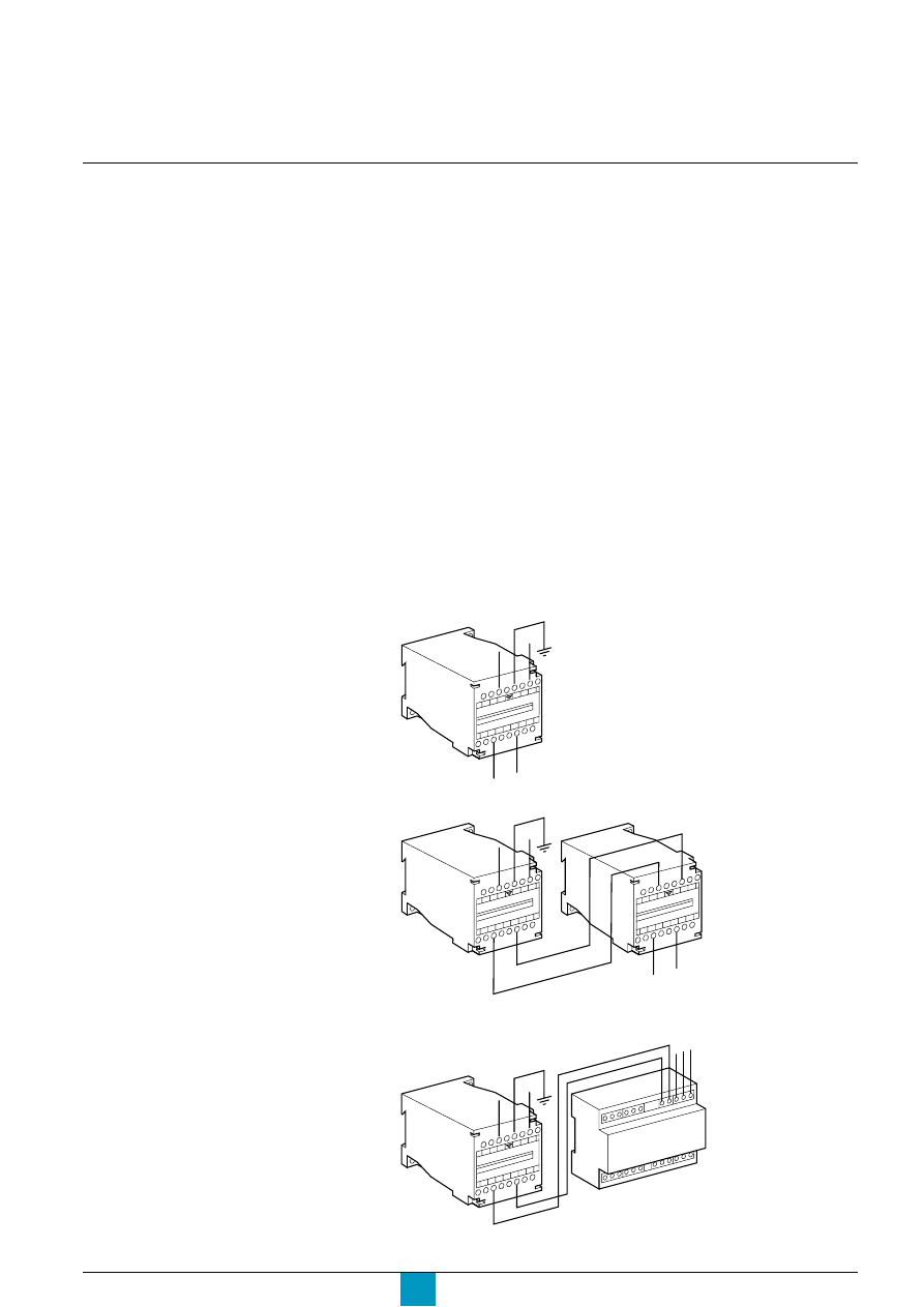
Micrologic P
Schneider Electric
77
Power supply
AD power-supply module
The AD power-supply module provides auxiliary power for the control-unit functions
listed below:
c
graphic display:
v
the display goes on as soon as the circuit breaker is closed
v
display is possible even with the circuit breaker open if it is equipped with an
auxiliary power source or an external voltage-measurement input
v
the long-time, short-time, instantaneous and earth-fault protection functions
operate under all circumstances on their own power
c
activation of an alarm and an output relay
An alarm may be linked with an output relay if the 24 V power-supply module is
installed
c
date and time
If a communications module is not installed, a power-supply module should be
installed to avoid having to enter the date and time following each circuit-breaker
trip.
In conjunction with the BAT battery module, the AD power-supply module can be
used to save data.
The AD power-supply module can supply the following voltages:
c
110 V AC
c
220 V AC
c
380 V AC
c
24 / 30 V DC
c
48 / 60 V DC
c
125 V DC.
c
wiring diagrams
v
reliable or backed-up auxiliary system
v
auxiliary system without back-up
c
supply with the MC6 module
L3
L4
G1
G2
+
–
Inpu
t
220
VAC
Outp
ut
24V
DC
AD 2
20V
F1
-
F2
+
L3
L4
G1
G2
+
–
Inpu
t
220
VAC
Outp
ut
24V
DC
AD 2
20V
H3
H4
H2
H1
-
+
Inpu
t
24V
DC
Outp
ut
24V
DC
BAT
24V
F1
-
F2
+
+
-
E60449A
E60448A
E60447A
L3
L4
G1
G2
+
–
Inpu
t
220V
AC
Outp
ut
24V
DC
AD 2
20V
M6C
17
25
19 21
23
Q1 Q2
Q3

Micrologic P
Schneider Electric
78
Using the AD power-supply module
circuit breaker
closed
open
open
voltage-measurement inputs
powered
powered
not powered
communications option
no
no
no
M2C, M6C programmable-contacts option
yes
yes
yes
protection function
no
no
no
display function
no
(1)
no
(2)
yes
time-stamping function
no
no
yes
(3)
circuit-breaker status indications and control
no
no
no
via communications bus
identification, settings, operation and maintenance aids
no
(1)
no
(2)
yes
via communications bus
(1) except for Micrologic A control units (if current < 20% In)
(2) except for Micrologic A control units
(3) the time setting is manual and can be carried out automatically by the supervisor via the communications bus.
None of the protection functions on the control unit require an auxiliary source.
However, the 24 V DC external power-supply (AD module) is required for certain
operating configurations as indicated in the table below.
c
if the 24 V DC external power supply (AD module) is used, the maximum cable
length between 24 V DC (G1, G2) and the control unit (F1-, F2+) must not exceed
10 metres.
c
the communications bus requires its own 24 V DC power source (E1, E2).
This source is not the same as the 24 V DC external power-supply module (F1-, F2+).
c
the BAT battery module, mounted in series upstream of the AD module, ensures
an uninterrupted supply of power if the AD module power supply fails.
c
the voltage-measurement inputs are standard equipment on the downstream
connectors of the circuit breaker.
External connections are possible using the PTE external voltage-measurement
input option. With this option, the internal voltage-measurement inputs are
disconnected and terminals VN, V1, V2 and V3 are connected only to the
Micrologic P control unit.
The PTE option is required for voltages less than 100 V and greater than 690 V
(in which case a voltage transformer is required).
For three-pole devices, the system is supplied with terminal VN connected only to
the Micrologic P control unit.
When the PTE option is implemented, the voltage-measurement input must be
protected against short-circuits. Installed as close as possible to the busbars, this
protection function is ensured by a P25M circuit breaker (1 A rating) with an
auxiliary contact (cat. no. 21104 and 21117). This voltage-measurement input is
reserved exclusively for the control unit and must not ever be used to supply other
circuits outside the switchboard.
Technical appendix
Power supply
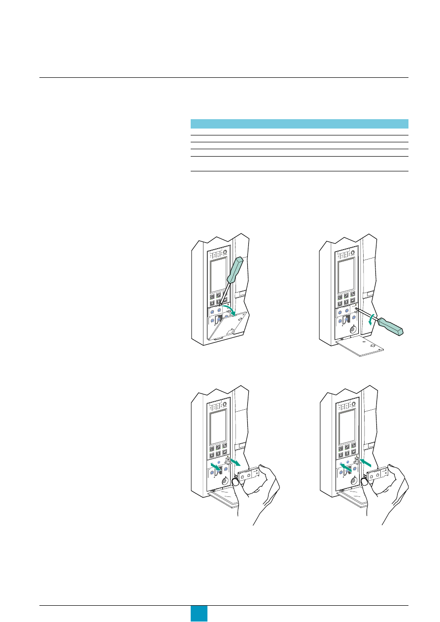
Micrologic P
Schneider Electric
79
Caution!
Following any modifications to the long-
time rating plug, all control-unit protection
parameters must be checked.
Changing the long-time
rating plug
Select the long-time rating plug
A number of setting ranges for the long-time current setting are available on
Micrologic P control units by changing the long-time rating plug.
The available rating plugs are listed below.
Part number
Setting range for the Ir value
33542
standard
0.4 to 1 x Ir
33543
low setting
0.4 to 0.8 x Ir
33544
high setting
0.8 to 1 x Ir
33545
without long-time protection
Change the long-time rating plug
Proceed in the following manner.
2. open the protective
cover of the control unit
3. completely remove
the long-time rating plug screw
E60321A
E60322A
4. snap out the rating
plug
5. clip in the new rating plug
E60323A
E60324A
6. refit the screw for the
long-time rating plug
7. check and/or modify the
control-unit settings
Caution!
If no long-time rating plug is installed, the
control unit continues to operate under the
following downgraded conditions:
c
the long-time current setting Ir is 0.4
c
the long-time tripping delay tr
corresponds to the value indicated by the
adjustment dial
c
the earth-leakage protection function is
disabled
c
the voltage-measurement inputs are
disconnected.
Micr
olog
ic 5.0
P
Micr
ologic 5.0 P
.4
.5
.6
.7
.8 .9
.95
.98
1
long
time
alarm
Ir
x In
.5
1
2
4
8 12
16
20
tr
(s)
@ 6
Ir
24
Micr
ologic 5.0 P
.4
.5
.6
.7
.8 .9
.95
.98
1
long
time
alarm
Ir
x In
.5
1
2
4
8 12
16
20
tr
(s)
@ 6
Ir
24
1. open the circuit breaker
Micr
ologic 5.0 P

Micrologic P
Schneider Electric
80
Technical appendix
Thermal memory
Thermal memory
The thermal memory is a means to simulate temperature rise and cooling caused
by changes in the flow of current in the conductors.
These changes may be caused by:
c
repetitive motor starting
c
loads fluctuating near the protection settings
c
repeated circuit-breaker closing on a fault.
Control units without a thermal memory (contrary to bimetal-strip thermal
protection) do not react to the above types of overloads because they do not last
long enough to cause tripping. However, each overload produces a temperature
rise and the cumulative effect can lead to dangerous overheating.
Control units with a thermal memory record the temperature rise caused by each
overload. Even very short overloads produce a temperature rise that is stored in
the memory.
This information stored in the thermal memory reduces the tripping time.
Micrologic control units and thermal memory
All Micrologic control units are equipped as standard with a thermal memory.
c
for all protection functions, prior to tripping, the temperature-rise and cooling time
constants are equal and depend on the tripping delay in question:
v
if the tripping delay is short, the time constant is low
v
if the tripping delay is long, the time constant is high.
c
for long-time protection, following tripping, the cooling curve is simulated by the
control unit. Closing of the circuit breaker prior to the end of the time constant
(approximately 15 minutes) reduces the tripping time indicated in the tripping
curves.
Short-time protection and intermittent faults
For the short-time protection function, intermittent currents that do no provoke
tripping are stored in the Micrologic P memory.
This information is equivalent to the long-time thermal memory and reduces the
tripping delay for the short-time protection.
Earth-fault protection and intermittent faults
The earth-fault protection implements the same function as the short-time
protection (see above).

Micrologic P
Schneider Electric
81
Data available via the COM
communications option
The COM communications option can be used to remotely access the Micrologic P
measurement, setting, maintenance and protection values.
Measurements
c
currents
v
instantaneous currents
v
maximum instantaneous currents
v
average instantaneous currents
v
instantaneous-current unbalance per phase
v
maximum instantaneous-current unbalance per phase
c
demand current
v
demand current per phase
v
maximum demand current per phase since last reset
v
recommended demand current per phase
v
time-stamping of demand-current maximums
c
voltages
v
phase-to-neutral and phase-to-phase voltages
v
average phase-to-neutral and phase-to-phase voltages
v
phase-to-neutral and phase-to-phase voltage unbalance
v
maximum phase-to-neutral and phase-to-phase voltage unbalance
c
active power per phase
c
demand power
v
demand power per phase
v
maximum demand power per phase since last reset
v
maximum recommended demand power per phase
v
time-stamping of demand-power maximums
c
energy
v
total active energy
v
positively incremented energy
v
negatively incremented energy
c
system frequency
c
interval between last update of real-time values and the current table
c
update date of demand currents, demand power and energy
Setup
c
setting of the control-unit date and time
c
password for the measurement module
c
control-unit ID code
c
control-unit ID name
c
selection of the measurement calculation algorithm
c
sign convention for the active power
c
total-energy measurement mode
c
scale factors
c
interval for the demand-current calculation window
c
demand-power calculation mode
c
interval for the demand-power calculation window
c
battery-charge indication
c
trip and alarm histories
c
operation counter and contact-wear indicator
Protection
c
circuit-breaker rated current
c
type of neutral protection
c
long-time I
2
t protection settings
c
long-time Idmtl protection settings
c
short-time protection settings
c
instantaneous-protection settings
c
earth-fault protection settings
c
earth-leakage protection settings
c
current-unbalance, I
t
alarm and maximum-current protection settings
c
voltage-protection settings
c
setting for other protection functions

Micrologic P
Schneider Electric
82
Technical appendix
Long-time I
2
t and Idmtl protection
Threshold and time-delay settings
Type
Range
Factory setting
Step
Accuracy
Ir current setting
0.4 to In
maximum
1 A
1.05 to 1.20 Ir
tr tripping delay
0.5 to 24 s
maximum
0.5 s
- 20 %, + 0 %
Short-time protection
Type
Range
Factory setting
Step
Accuracy
Isd pickup
1.5 to 10 Ir
maximum
10 A
±
10 %
tsd tripping delay
0 - 0.1 - 0.2 - 0.3 - 0.4 s
maximum
0.1 s
Instantaneous protection
Type
Range
Factory setting
Step
Accuracy
Ii pickup
2 to 15 In or off
maximum
10 A
±
10 %
Earth-fault protection on Micrologic 6.0 P
Type
Range
Factory setting
Step
Accuracy
Ig pickup
maximum
1 A
±
10 %
tg tripping delay
0 - 0.1 - 0.2 - 0.3 - 0.4 s
maximum
0.1 s
Micrologic P
Schneider Electric
83
Type
Range
Factory setting
Step
Accuracy
current unbalance I unbal
Pickup threshold
5% to 60%
60 %
1 %
-10 %, +0 %
Dropout threshold
5% of pickup threshold
pickup threshold
1 %
-10 %, +0 %
Pickup time delay
1 to 40 s
40 s
1 s
-20 %, +0 %
Dropout time delay
10 to 360 s
10 s
1 s
-20 %, +0 %
earth-fault I
t
t
t
t
t
alarm
Pickup threshold
20 to 1200 A
1200 A
1 A
+/- 15 %
Dropout threshold
20 A to pickup threshold
pickup threshold
1 A
+/- 15 %
Pickup time delay
1 to 10 s
10 s
0.1 s
-20 %, +0 %
Dropout time delay
1 to 10 s
1 s
0.1 s
-20 %, +0 %
earth-leakage I
t
t
t
t
t
alarm
Pickup threshold
0.5 to 30 A
30 A
0.1 A
-20 %, +0 %
Dropout threshold
0.5 A to pickup threshold
pickup threshold
0.1 A
-20 %, +0 %
Pickup time delay
1 to 10 s
10 s
0.1 s
-20 %, +0 %
Dropout time delay
1 to 10 s
1 s
0.1 s
-20 %, +0 %
maximum current 1 max, 2 max, 3 max, N max
Pickup threshold
0.2 to 10 In
In
1 A
±
6.6%
Dropout threshold
0.2 In to pickup threshold
pickup threshold
1 A
±
6.6%
Pickup time delay
15 to 1500 s
1500 s
1 s
-20 %, +0 %
Dropout time delay
15 to 3000 s
15 s
1 s
-20 %, +0 %
Current protection
Voltage protection
I
I
I
I
Type
Range
Factory setting
Step
Accuracy
minimum voltage U min
Pickup threshold
100 V to U max pickup threshold
100 V
5 V
-5 %, +0 %
Dropout threshold
pickup threshold to U max
pickup threshold
5 V
-5 %, +0 %
pickup threshold
Pickup time delay
0.2 to 5 s
5 s
0.1 s
-0 %, +20 %
Dropout time delay
0.2 to 36 s
0.2 s
0.1 s
-0 %, +20 %
maximum voltage U max
Pickup threshold
U min pickup threshold to 1200 V
725 V
5 V
-0 %, +5 %
Dropout threshold
100 V to pickup threshold
pickup threshold
5 V
-0 %, +5 %
Pickup time delay
0.2 to 5 s
5 s
0.1 s
-0 %, +20 %
Dropout time delay
0.2 to 36 s
0.2 s
0.1 s
-0 %, +20 %
voltage unbalance U unbal
Pickup threshold
2 to 30%
30 %
1 %
-10 %, +0 %
Dropout threshold
2% to pickup threshold
pickup threshold
1 %
-10 %, +0 %
Pickup time delay
1 to 40 s
40 s
1 s
-20 %, +0 %
Dropout time delay
10 to 360 s
10 s
1 s
-20 %, +0 %
Micrologic P
Schneider Electric
84
Technical appendix
Other protection
Load shedding and reconnection
Threshold and time-delay settings
Type
Range
Factory setting
Step
Accuracy
reverse power rP max
Pickup threshold
5 to 500 kW
500 kW
5 kw
±
2.5%
Dropout threshold
5 kW to pickup threshold
pickup threshold
5 kw
±
2.5%
Pickup time delay
0.2 to 20 s
20 s
0.1 s
-0 %, +20 %
Dropout time delay
1 to 360 s
1 s
0.1 s
-0 %, +20 %
maximum frequency F max
Pickup threshold
F min pickup threshold to 540 Hz
65 Hz
0.5 Hz
±
0.5 Hz
Dropout threshold
45 Hz to pickup threshold
pickup threshold
0.5 Hz
±
0.5 Hz
Pickup time delay
0.2 to 5 s
5 s
0.1 s
-0 %, +20 %
Dropout time delay
1 to 36 s
1 s
0.1 s
-0 %, +20 %
minimum frequency F min
Pickup threshold
45 Hz to F max pickup threshold
45 Hz
0.5 Hz
±
0.5 Hz
Dropout threshold
pickup threshold to F max
pickup threshold
0.5 Hz
±
0.5 Hz
pickup threshold
Pickup time delay
0.2 to 5 s
5 s
0.1 s
-0 %, +20 %
Dropout time delay
1 to 36 s
1 s
0.1 s
-0 %, +20 %
phase rotation
Pickup threshold
Ph1, Ph2, Ph3 or Ph1, Ph3, Ph2
Ph1, Ph2, Ph3
none
none
Dropout threshold
pickup threshold
pickup threshold
none
none
Pickup time delay
0.3 s
0.3 s
none
+/- 20 %
Dropout time delay
0.3 s
0.3 s
none
+/- 20 %
Type
Range
Factory setting
Step
Accuracy
current I
Pickup threshold
50 to 100% Ir
100 % Ir
1 %
±
6 %
Dropout threshold
30% Ir to shedding threshold
shedding threshold
1 %
±
6 %
Pickup time delay
20 to 80% tr
80 % tr
1 %
-20 %, +0 %
Dropout time delay
10 to 600 s
10 s
1 s
-20 %, +0 %
power P
Pickup threshold
200 to 10 000 kW
10 000 kW
50 kW
±
2.5 Hz
Dropout threshold
100 kW to shedding threshold
shedding threshold
50 kW
±
2.5 Hz
Pickup time delay
10 to 3600 s
3600 s
10 s
-20 %, +0 %
Dropout time delay
10 to 3600 s
10 s
10 s
-20 %, +0 %

Micrologic P
Schneider Electric
85
Other settings
M2C / M6C contacts
Type
Range
Factory setting
Step
time-delay
1 - 360 s
360 s
1 s
latching
time delay
Micrologic setup
Type
Range
Factory setting
Step
language
English US
English
English UK
French
German
Italian
Spanish
date / hour
1 s
circuit-breaker
4 ASCII
"set !"
selection
characters
(A to Z, 0 to 9)
neutral TC
no TC
voltage transformer
primary voltage
min. 100 V, max. 1150 V
690 V
1 V
secondary voltage
min. 100 V, max. 690 V
690 V
1 V
system
50/60 Hz
50/60 Hz
frequency
or
400 Hz
Measurement setup
Type
Range
Factory setting
Step
system type
3
Φ
, 3 w, 3 CT
3
Φ
, 4 w, 4 CT
3
Φ
, 4 w, 3 CT
3
Φ
, 4 w, 4 CT
demand-current
5 to 60 minutes
15 minutes
1 minute
calculation
interval
demand-power
calculation
type of window
block or sliding
sliding
calculation interval
5 to 60 minutes
15 minutes
1 minute
active power flow
P+
P+
P-
(flow from top to
bottom)
sign convention
IEEE
IEEE
IEEE alternate
IEC
Type
Range
Fatory setting
com parameter
MODBUS
adress
1-47
47
baud rate
9600 to 19 200 bauds
19 200 bauds
parity
even
even
none
remote settings
access authorisation
yes / no
yes
access code
0000 to 9999
0000
remote
manual
automatic
control
automatic
Type
Range
Fatory setting
current protection
alarm / trip
alarm
voltage protection
other protection
power flow
top fed / bottom fed
top fed
Communication setup
Protection setup
Micrologic P
Schneider Electric
86
Measurement setting ranges and accuracy
Type
Range
Accuracy
instantaneous current
I1
0 to 32 kA
±
1.5 %
I2
0 to 32 kA
±
1.5 %
I3
0 to 32 kA
±
1.5 %
IN
0 to 32 kA
±
1.5 %
I
t
0 to 32 kA
±
1.5 %
I1 max
0 to 32 kA
±
1.5 %
I2 max
0 to 32 kA
±
1.5 %
I3 max
0 to 32 kA
±
1.5 %
IN max
0 to 32 kA
±
1.5 %
I
t
max
0 to 32 kA
±
1.5 %
demand current
1
0 to 32 kA
±
1.5 %
2
0 to 32 kA
±
1.5 %
3
0 to 32 kA
±
1.5 %
N
0 to 32 kA
±
1.5 %
1 max
0 to 32 kA
±
1.5 %
2 max
0 to 32 kA
±
1.5 %
3 max
0 to 32 kA
±
1.5 %
N max
0 to 32 kA
±
1.5 %
phase-to-phase voltages
U12
0 to 1200 V
±
0.5 %
U23
0 to 1200 V
±
0.5 %
U31
0 to 1200 V
±
0.5 %
phase-to-neutral voltages
U1N
0 to 1200 V
±
0.5 %
U2N
0 to 1200 V
±
0.5 %
U3N
0 to 1200 V
±
0.5 %
average voltage
U avg
0 to 1200 V
±
0.5 %
voltage unbalance
U unbal
0 to 100 %
±
0.5 %
instantaneous power
P
0 to 32 MW
±
2 %
Q
0 to 32 Mvar
±
2 %
S
0 to 32 MVA
±
2 %
power factor
PF
-1 to +1
±
0.01
demand power
P
0 to 32 MW
±
2 %
Q
0 to 32 Mvar
±
2 %
S
0 to 32 MVA
±
2 %
P max
0 to 32 MW
±
2 %
Q max
0 to 32 Mvar
±
2 %
S max
0 to 32 MVA
±
2 %
total energy
E.P
-10
10
GWh to +10
10
GWh
±
2 %
E.Q
-10
10
Gvarh to +10
10
Gvarh
±
2 %
E.S
-10
10
GVAh to +10
10
GVAh
±
2 %
total energy in
E.P
-10
10
GWh to +10
10
GWh
±
2 %
E.Q
-10
10
Gvarh to +10
10
Gvarh
±
2 %
total energy out
E.P
-10
10
GWh to +10
10
GWh
±
2 %
E.Q
-10
10
Gvarh to +10
10
Gvarh
±
2 %
frequency
F
45 Hz to 440 Hz
0.1 Hz
Measurement setting ranges
and accuracy
Technical appendix
I
I
I
I
I
I
I
I

Micrologic P
Schneider Electric
87

Micrologic P
Schneider Electric
88
Index
A
Active, reactive, apparent energy
23
Active, reactive, apparent power
23
Active-power flow
36
AD power-supply module
77
Address
38
Alarm
24, 30, 40
Alarm history
26, 59
B
B Bus
38
BAT battery module
77
Baud rate
38
Buttons
5, 6, 21
C
Circuit-breaker selection
33
COM communications option
29, 38, 81
Contact wear
26, 60
Contacts
25, 30
Control-unit battery
61
Control-unit identification
4
D
Date and time
32
Deactivation
17, 18, 19, 20, 25
Demand current
22
Demand power
23
Demand power
23
Demand-current calculation
22, 35
Demand-power calculation
23, 36
Double neutral protection
15
DT
13
Dt tripping delay
16
E
Earth-fault / Earth-leakage protection test
5, 62
Earth-fault protection
16
Earth-leakage protection
16
EIT
13
F
F max
19
F min
19
Fault
27
Frequency
23
Full neutral protection
11, 15
G
Graphic display
5
H
Half neutral protection
11, 15
History, maintenance and setup menu
65, 68
HVF
13
I
I demand
17
I max
17
I unbal
17
I
t
alarm
17
Idmtl
13
IDn pickup
16
Ig pickup
16
Ii pickup
14
Infrared link
5
Instantaneous current
22
Instantaneous protection
14
Ir current setting
12, 13
Isd pickup
14
I
2
t
12

Micrologic P
Schneider Electric
89
L
Language
32
Latching
31
Lead seal for cover
5
LEDs
5, 27
Load shedding / reconnection
20
Long-time alarm
27
Long-time Idmtl protection
13
Long-time I
2
t protection
12
Long-time plug
5, 12, 79
M
M2C / M6C
25, 30, 77
Main screen
64
Maximum demand current
22
Maximum demand power
23
Maximum instantaneous current
22
Metering menu
64, 66
ModBus
38
N
Negatively incremented energy
23
Neutral CT
34
Neutral protection
13, 15
No neutral protection
11, 15
O
Operation counter
26, 60
P
Parity
38
Phase rotation
19
Phase-to-neutral and phase-to-phase voltages
22
Pickup
17, 18, 19, 20, 25
Portable test kit
62
Positively incremented energy
23
Power factor
23
Power supply
77
Protection menu
65, 71
R
Remote settings
38
Resetting the alarms and fault indications
5, 58
Resetting the contacts
31
Resetting the energy values
23, 56
Resetting the maximum demand current values
23, 51
Resetting the maximum demand power values
23, 55
Resetting the maximum instantaneous current values
22, 50
Resetting the operation counter
60
rP max
19
S
Selfprotection
14, 28
Setting dials
5, 6, 11, 21
Short-time protection
14
Sign convention
37
SIT
13
System frequency
34
System type
35
T
Tab
7
Temperature
28
Test connector
5
tg tripping delay
16
Thermal memory
12, 80
tr tripping delay
12, 13
Transformation ratio
34
Trip
24, 40
Trip history
26, 59
Tripping curves
74
tsd tripping delay
14

Micrologic P
Schneider Electric
90
Index
U
U max
18
U min
18
U unbal
18, 22
V
VIT
13
Voltage U average
18, 22
Z
Zone selective interlocking
76

Schneider Electric Industries SA
Postal address
5, rue Nadar
92506 Rueil-Malmaison Cedex
France
Tel: +33 (0)1 41 29 82 00
Fax:+33 (0)1 47 51 80 20
http://www.schneider-electric.com
Layout by: HeadLines
Printed by:
As standards, specifications and design change from time to time, always ask for confirmation
of the information given in this publication.
This document has been printed on ecological paper
Document Outline
- MICROLOGIC CONTROL UNITS 5.0 P, 6.0 P, 7.0 P
- CONTENTS
- DISCOVERING MICROLOGIC P
- OVERVIEW OF FUNCTIONS
- SETUP
- PROTECTION SETTINGS
- Fine adjustment of the long-time I 2 t, short-time and instantaneous settings
- Fine adjustment of the long-time Idmtl, short-time and instantaneous settings
- Fine adjustment of the earth-fault and earth-leakage protection setting
- Setting the neutral protection
- Setting the I , I unbal, max, U min, U max, U unbal, rP max, F min, F max, and phase-rotation protection functions
- Setting load shedding / reconnection
- METERING
- MAINTENANCE
- MENU ACCESS
- TECHNICAL APPENDIX
- INDEX
Wyszukiwarka
Podobne podstrony:
05 MICROLOGIC 2 0A 7 0A MANUAL
05 MICROLOGIC 2 0 5 0 MANUAL
0p, STUDIA, Polibuda - semestr II, Materiały budowlane
Akumulator do HITACHI UH Serie UH 0P
1 11f ZGRZEWANIE ELEKTRYCZNE 0P Nieznany
05 INSTRUCTION MANUAL COUPLING M8090901A
JobEditorNX Manual EN 05
podrecznik 2 18 03 05
regul praw stan wyjątk 05
05 Badanie diagnostyczneid 5649 ppt
Podstawy zarządzania wykład rozdział 05
05 Odwzorowanie podstawowych obiektów rysunkowych
05 Instrukcje warunkoweid 5533 ppt
05 K5Z7
więcej podobnych podstron